WO2024069966A1 - 多重殻タンク - Google Patents
多重殻タンク Download PDFInfo
- Publication number
- WO2024069966A1 WO2024069966A1 PCT/JP2022/036793 JP2022036793W WO2024069966A1 WO 2024069966 A1 WO2024069966 A1 WO 2024069966A1 JP 2022036793 W JP2022036793 W JP 2022036793W WO 2024069966 A1 WO2024069966 A1 WO 2024069966A1
- Authority
- WO
- WIPO (PCT)
- Prior art keywords
- tank
- pipe
- shell
- gas
- inter
- Prior art date
- Legal status (The legal status is an assumption and is not a legal conclusion. Google has not performed a legal analysis and makes no representation as to the accuracy of the status listed.)
- Ceased
Links
Images


Classifications
-
- F—MECHANICAL ENGINEERING; LIGHTING; HEATING; WEAPONS; BLASTING
- F17—STORING OR DISTRIBUTING GASES OR LIQUIDS
- F17C—VESSELS FOR CONTAINING OR STORING COMPRESSED, LIQUEFIED OR SOLIDIFIED GASES; FIXED-CAPACITY GAS-HOLDERS; FILLING VESSELS WITH, OR DISCHARGING FROM VESSELS, COMPRESSED, LIQUEFIED, OR SOLIDIFIED GASES
- F17C3/00—Vessels not under pressure
- F17C3/02—Vessels not under pressure with provision for thermal insulation
- F17C3/04—Vessels not under pressure with provision for thermal insulation by insulating layers
-
- B—PERFORMING OPERATIONS; TRANSPORTING
- B63—SHIPS OR OTHER WATERBORNE VESSELS; RELATED EQUIPMENT
- B63B—SHIPS OR OTHER WATERBORNE VESSELS; EQUIPMENT FOR SHIPPING
- B63B25/00—Load-accommodating arrangements, e.g. stowing, trimming; Vessels characterised thereby
- B63B25/02—Load-accommodating arrangements, e.g. stowing, trimming; Vessels characterised thereby for bulk goods
- B63B25/08—Load-accommodating arrangements, e.g. stowing, trimming; Vessels characterised thereby for bulk goods fluid
- B63B25/12—Load-accommodating arrangements, e.g. stowing, trimming; Vessels characterised thereby for bulk goods fluid closed
- B63B25/16—Load-accommodating arrangements, e.g. stowing, trimming; Vessels characterised thereby for bulk goods fluid closed heat-insulated
-
- F—MECHANICAL ENGINEERING; LIGHTING; HEATING; WEAPONS; BLASTING
- F17—STORING OR DISTRIBUTING GASES OR LIQUIDS
- F17C—VESSELS FOR CONTAINING OR STORING COMPRESSED, LIQUEFIED OR SOLIDIFIED GASES; FIXED-CAPACITY GAS-HOLDERS; FILLING VESSELS WITH, OR DISCHARGING FROM VESSELS, COMPRESSED, LIQUEFIED, OR SOLIDIFIED GASES
- F17C13/00—Details of vessels or of the filling or discharging of vessels
- F17C13/004—Details of vessels or of the filling or discharging of vessels for large storage vessels not under pressure
-
- F—MECHANICAL ENGINEERING; LIGHTING; HEATING; WEAPONS; BLASTING
- F17—STORING OR DISTRIBUTING GASES OR LIQUIDS
- F17C—VESSELS FOR CONTAINING OR STORING COMPRESSED, LIQUEFIED OR SOLIDIFIED GASES; FIXED-CAPACITY GAS-HOLDERS; FILLING VESSELS WITH, OR DISCHARGING FROM VESSELS, COMPRESSED, LIQUEFIED, OR SOLIDIFIED GASES
- F17C2201/00—Vessel construction, in particular geometry, arrangement or size
- F17C2201/01—Shape
- F17C2201/0104—Shape cylindrical
-
- F—MECHANICAL ENGINEERING; LIGHTING; HEATING; WEAPONS; BLASTING
- F17—STORING OR DISTRIBUTING GASES OR LIQUIDS
- F17C—VESSELS FOR CONTAINING OR STORING COMPRESSED, LIQUEFIED OR SOLIDIFIED GASES; FIXED-CAPACITY GAS-HOLDERS; FILLING VESSELS WITH, OR DISCHARGING FROM VESSELS, COMPRESSED, LIQUEFIED, OR SOLIDIFIED GASES
- F17C2201/00—Vessel construction, in particular geometry, arrangement or size
- F17C2201/05—Size
- F17C2201/052—Size large (>1000 m3)
-
- F—MECHANICAL ENGINEERING; LIGHTING; HEATING; WEAPONS; BLASTING
- F17—STORING OR DISTRIBUTING GASES OR LIQUIDS
- F17C—VESSELS FOR CONTAINING OR STORING COMPRESSED, LIQUEFIED OR SOLIDIFIED GASES; FIXED-CAPACITY GAS-HOLDERS; FILLING VESSELS WITH, OR DISCHARGING FROM VESSELS, COMPRESSED, LIQUEFIED, OR SOLIDIFIED GASES
- F17C2201/00—Vessel construction, in particular geometry, arrangement or size
- F17C2201/05—Size
- F17C2201/054—Size medium (>1 m3)
-
- F—MECHANICAL ENGINEERING; LIGHTING; HEATING; WEAPONS; BLASTING
- F17—STORING OR DISTRIBUTING GASES OR LIQUIDS
- F17C—VESSELS FOR CONTAINING OR STORING COMPRESSED, LIQUEFIED OR SOLIDIFIED GASES; FIXED-CAPACITY GAS-HOLDERS; FILLING VESSELS WITH, OR DISCHARGING FROM VESSELS, COMPRESSED, LIQUEFIED, OR SOLIDIFIED GASES
- F17C2203/00—Vessel construction, in particular walls or details thereof
- F17C2203/03—Thermal insulations
- F17C2203/0375—Thermal insulations by gas
-
- F—MECHANICAL ENGINEERING; LIGHTING; HEATING; WEAPONS; BLASTING
- F17—STORING OR DISTRIBUTING GASES OR LIQUIDS
- F17C—VESSELS FOR CONTAINING OR STORING COMPRESSED, LIQUEFIED OR SOLIDIFIED GASES; FIXED-CAPACITY GAS-HOLDERS; FILLING VESSELS WITH, OR DISCHARGING FROM VESSELS, COMPRESSED, LIQUEFIED, OR SOLIDIFIED GASES
- F17C2203/00—Vessel construction, in particular walls or details thereof
- F17C2203/06—Materials for walls or layers thereof; Properties or structures of walls or their materials
- F17C2203/0602—Wall structures; Special features thereof
- F17C2203/0612—Wall structures
- F17C2203/0626—Multiple walls
- F17C2203/0629—Two walls
-
- F—MECHANICAL ENGINEERING; LIGHTING; HEATING; WEAPONS; BLASTING
- F17—STORING OR DISTRIBUTING GASES OR LIQUIDS
- F17C—VESSELS FOR CONTAINING OR STORING COMPRESSED, LIQUEFIED OR SOLIDIFIED GASES; FIXED-CAPACITY GAS-HOLDERS; FILLING VESSELS WITH, OR DISCHARGING FROM VESSELS, COMPRESSED, LIQUEFIED, OR SOLIDIFIED GASES
- F17C2221/00—Handled fluid, in particular type of fluid
- F17C2221/01—Pure fluids
- F17C2221/012—Hydrogen
-
- F—MECHANICAL ENGINEERING; LIGHTING; HEATING; WEAPONS; BLASTING
- F17—STORING OR DISTRIBUTING GASES OR LIQUIDS
- F17C—VESSELS FOR CONTAINING OR STORING COMPRESSED, LIQUEFIED OR SOLIDIFIED GASES; FIXED-CAPACITY GAS-HOLDERS; FILLING VESSELS WITH, OR DISCHARGING FROM VESSELS, COMPRESSED, LIQUEFIED, OR SOLIDIFIED GASES
- F17C2223/00—Handled fluid before transfer, i.e. state of fluid when stored in the vessel or before transfer from the vessel
- F17C2223/01—Handled fluid before transfer, i.e. state of fluid when stored in the vessel or before transfer from the vessel characterised by the phase
- F17C2223/0146—Two-phase
- F17C2223/0153—Liquefied gas, e.g. LPG, GPL
- F17C2223/0161—Liquefied gas, e.g. LPG, GPL cryogenic, e.g. LNG, GNL, PLNG
-
- F—MECHANICAL ENGINEERING; LIGHTING; HEATING; WEAPONS; BLASTING
- F17—STORING OR DISTRIBUTING GASES OR LIQUIDS
- F17C—VESSELS FOR CONTAINING OR STORING COMPRESSED, LIQUEFIED OR SOLIDIFIED GASES; FIXED-CAPACITY GAS-HOLDERS; FILLING VESSELS WITH, OR DISCHARGING FROM VESSELS, COMPRESSED, LIQUEFIED, OR SOLIDIFIED GASES
- F17C2270/00—Applications
- F17C2270/01—Applications for fluid transport or storage
- F17C2270/0102—Applications for fluid transport or storage on or in the water
-
- F—MECHANICAL ENGINEERING; LIGHTING; HEATING; WEAPONS; BLASTING
- F17—STORING OR DISTRIBUTING GASES OR LIQUIDS
- F17C—VESSELS FOR CONTAINING OR STORING COMPRESSED, LIQUEFIED OR SOLIDIFIED GASES; FIXED-CAPACITY GAS-HOLDERS; FILLING VESSELS WITH, OR DISCHARGING FROM VESSELS, COMPRESSED, LIQUEFIED, OR SOLIDIFIED GASES
- F17C2270/00—Applications
- F17C2270/01—Applications for fluid transport or storage
- F17C2270/0134—Applications for fluid transport or storage placed above the ground
Definitions
- This disclosure relates to the structure of a multi-shell tank that contains low-temperature liquefied gas.
- a multi-shell tank is known as a tank for storing liquefied gas, which has an inner tank that stores the liquefied gas and an outer tank that surrounds the inner tank, with a heat-insulating layer provided between the inner and outer tanks.
- Patent Document 1 discloses this type of multi-shell tank.
- the multi-shell tank disclosed in Patent Document 1 comprises an inner tank for storing liquefied gas, an outer tank that houses the inner tank, and a thermal barrier layer made of insulating material disposed in the area between the inner tank and the outer tank.
- the space between the inner and outer tanks is filled with the same gas as the vaporized gas of the liquefied gas contained in the inner tank, or with an inert gas.
- an air supply and exhaust process is carried out in which the gas present between the inner and outer tanks is forcibly exhausted and new gas is introduced.
- insulation materials, supporting materials, strength members, etc. that make up the thermal barrier are arranged, and there are places where gas does not flow easily.
- the gas flow is likely to be stagnant in the places where gas does not flow easily between the inner and outer tanks, and there is a risk of the efficiency of the air supply and exhaust process decreasing.
- the present disclosure has been made in consideration of the above circumstances, and its purpose is to provide a technology that improves the efficiency of the air supply and exhaust process between tanks in a multi-shell tank that includes a first tank, a second tank surrounding the first tank, and a thermal barrier layer disposed between the first tank and the second tank and covering the first tank.
- a multi-shell tank comprises: A first tank; a second tank surrounding the first tank; a thermal barrier layer disposed between the first tank and the second tank and covering an outer wall of the first tank; The thermal insulation layer is provided with a first opening disposed in a first inter-tank region between the first tank and the thermal insulation layer, and a first pipe for air supply or exhaust extending to the outside through the space between the tanks.
- the present disclosure provides a technology that improves the efficiency of the air intake and exhaust process between tanks in a multi-shell tank that includes a first tank, a second tank surrounding the first tank, and a thermal barrier layer disposed between the first tank and the second tank and covering the first tank.
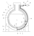
- FIG. 1 is a vertical cross-sectional view showing a schematic configuration of a multi-shell tank according to one embodiment of the present disclosure.
- FIG. 2 is an enlarged view of a tip portion of the first pipe.
- FIG. 3 is a diagram showing an example of the configuration of a first pipe and a second pipe having a shared portion.
- FIG. 4 is a diagram showing an example of the configuration of a first pipe having a plurality of first openings arranged in an annular shape.
- FIG. 5 is a diagram showing an example of the configuration of the first pipe having first openings both above and below the first tank.
- FIG. 1 is a vertical cross-sectional view showing a schematic configuration of a multi-shell tank 1 according to one embodiment of the present disclosure.
- the multi-shell tank 1 shown in FIG. 1 is a tank that stores low-temperature liquefied gas L.
- the liquefied gas L include liquefied hydrogen and liquefied natural gas.
- the multi-shell tank 1 may be mounted on a floating structure such as a ship or marine structure, or may be installed at a land base.
- the multi-shell tank 1 may be a cargo tank that stores liquefied gas L as cargo, or may be a fuel tank that stores liquefied gas L as fuel.
- the multi-shell tank 1 is a double-shell tank including a first tank 21 that contains liquefied gas L and a second tank 22 that surrounds the first tank 21.
- the first tank 21 and the second tank 22 are spaced apart in the radial direction of the multi-shell tank 1.
- the multi-shell tank 1 according to the present disclosure is not limited to a double-shell tank, and may have three or more shells (i.e., tanks) with an additional tank outside the second tank 22.
- the present disclosure can be applied to a multi-shell tank with three or more shells.
- a heat insulating layer 24 is disposed between the first tank 21 and the second tank 22 in the space 23 between the tanks.
- the heat insulating layer 24 covers the outer wall of the first tank 21 in the space 23 between the tanks, and suppresses heat input to the first tank 21.
- the heat insulating layer 24 is composed of, for example, a heat insulating panel.
- the multi-shell tank 1 is supported on the tank foundation 10 via supports 71 and 72.
- the tank foundation 10 is, for example, the hull of a floating structure such as a ship or marine structure, or the concrete foundation of a land base.
- the supports 71 and 72 are cylindrical bodies extending in a generally vertical direction, and mainly include a first skirt 71 that supports the first tank 21 and a second skirt 72 that supports the second tank 22.
- the first skirt 71 is surrounded by the second skirt 72.
- the upper end of the second skirt 72 is joined to the second tank 22, and the lower end of the second skirt 72 is fixed to the tank foundation 10.
- the upper end of the first skirt 71 is joined to the first tank 21 at the tank gap 23.
- the first skirt 71 passes through the tank gap 23, and the lower end of the first skirt 71 is fixed to the tank foundation 10. At the intersection of the first tank 21 and the first skirt 71, there is a narrow space between the first tank 21 and the first skirt 71, where the flow of gas is stagnant. In addition, at the intersection of the thermal insulation layer 24 that covers the first tank 21 and the first skirt 71, there is a narrow space surrounded by the thermal insulation layer 24 and the first skirt 71 where the flow of gas is stagnant.
- first inter-tank area 25 the area between the first tank 21 and the thermal insulation layer 24
- second inter-tank area 26 the area between the thermal insulation layer 24 and the second tank 22
- first inter-tank area 25 the area between the thermal insulation layer 24 and the second tank 22
- first inter-tank area 25 surrounding the first tank 21 and the second inter-tank area 26 surrounding the first inter-tank area 25 are formed in the inter-tank area 23.
- the first inter-tank area 25 and the second inter-tank area 26 may be spaces that are connected to each other, or may be spaces that are independent of each other.
- the first inter-tank area 25 may be formed in a gap provided between the outer wall of the first tank 21 and the thermal insulation layer 24, or may be formed by a gap or hole formed on the surface of the thermal insulation layer 24 facing the outer wall of the first tank 21.
- the space inside this recess 25a is also included in the first inter-tank area 25.
- each of the first intertank region 25 and the second intertank region 26 of the intertank 23 is filled with intertank gas G.
- the intertank gas G is the same type of gas as the vaporized gas of the liquefied gas L, or an inert gas.
- the liquefied gas L is liquid hydrogen
- hydrogen gas is used as the intertank gas G.
- nitrogen gas is used as the intertank gas G.
- the multi-shell tank 1 is equipped with a first pipe 3 and a second pipe 4 for supplying air to the space between the tanks 23 and exhausting air from the space between the tanks 23.
- the first pipe 3 and the second pipe 4 may be widely used for supply and exhaust processes involving exhausting air from and supplying air to the space between the tanks 23, such as filling the space between the tanks 23 with inter-tank gas G, gas replacement, cooling, and heating.
- the first pipe 3 has a first opening 31 that opens into the first intertank region 25.
- the first pipe 3 is mainly used for supplying air to and/or exhausting the first intertank region 25.
- one system of first pipe 3 is used for both supplying air and exhausting air, but there may also be a first pipe 3 for an air supply system having a first opening 31 as an air supply port, and a first pipe 3 for an exhaust system having a first opening 31 as an exhaust port.
- the first pipe 3 penetrates the second tank 22 and passes through the second inter-tank region 26 of the tank 23, and the first opening 31 provided at the tip portion 3a is located within the first inter-tank region 25.
- FIG 2 is an enlarged view of the tip portion 3a of the first pipe 3.
- the tip portion 3a of the first pipe 3 is provided with a first opening 31 that opens into the first inter-tank region 25.
- the tip portion 3a of the first pipe 3 is supported on the first tank 21 by a first support member 36 fixed to the first tank 21.
- the middle portion 3b of the first pipe 3 is disposed along the inner wall of the second tank 22 in the second inter-tank region 26, and is supported on the second tank 22 by a second support member 37 fixed to the second tank 22.
- the first pipe 3 has an expandable section 38 between the tip section 3a supported by the first support member 36 and the middle section 3b supported by the second support member 37.
- the expandable section 38 is, for example, made of a flexible hose.
- the change in the relative positions of the tip section 3a and the middle section 3b of the first pipe 3 is absorbed by the expansion or contraction of the expandable section 38, and the stress generated in the first pipe 3, the stress generated at the joint between the first support member 36 and the first tank 21, and the stress generated at the joint between the second support member 37 and the second tank 22 are reduced.
- the second pipe 4 has a second opening 41 that opens into the second intertank region 26.
- the second pipe 4 is mainly used for supplying and exhausting air to and from the second intertank region 26.
- the second pipe 4 is used for both supplying and exhausting air, but the second pipe 4 of the air supply system having the second opening 41 as an air supply port, and the second pipe 4 of the exhaust system having the second opening 41 as an exhaust port may also be provided.
- the second pipe 4 penetrates the second tank 22 and passes through the second inter-tank region 26 of the tank 23, and the second opening 41 provided at the tip is disposed within the second inter-tank region 26.
- the first pipe 3 and the second pipe 4 are independent pipes in the tank 23 of the multi-shell tank 1. However, the first pipe 3 and the second pipe 4 may share a part of the pipe.
- FIG. 3 is a diagram showing an example of the configuration of the first pipe 3 and the second pipe 4 having a shared part.
- a common pipe 30 that penetrates the second tank 22 and passes through the second inter-tank region 26 of the tank 23, a first branch pipe 35 connected to the common pipe 30 and having a first opening 31 at its tip, and a second branch pipe 45 connected to the common pipe 30 and having a second opening 41 at its tip.
- the combination of the common pipe 30 and the first branch pipe 35 functions as the first pipe 3
- the combination of the common pipe 30 and the second branch pipe 45 functions as the second pipe 4.
- the first pipe 3 has at least one first opening 31 that opens in the height range where the first tank 21 and the second tank 22 overlap in the vertical direction.
- the second pipe 4 has at least one second opening 41 that opens in the height range where the first tank 21 and the second tank 22 overlap in the vertical direction.
- the insulating material, supporting material, strength members, etc. that make up the thermal barrier layer 24 are concentrated, and there are places where gas does not flow easily. It is preferable that the openings 31, 41 are located in such places where gas does not flow easily.
- the first pipe 3 preferably has at least one first opening 31 arranged in a narrow portion sandwiched between the first tank 21 and the first skirt 71 at the intersection of the first tank 21 and the first skirt 71.
- the second pipe 4 preferably has a second opening 41 arranged in a narrow portion sandwiched between the thermal insulation layer 24 and the first skirt 71 at the intersection of the thermal insulation layer 24 and the first skirt 71.
- the flow of gas is more likely to be stagnant in narrow portions than in other portions, but supplying and/or exhausting air through the openings 31, 41 arranged in the narrow portions promotes the flow of gas in the narrow portions and improves the efficiency of the supply and exhaust process.
- the first pipe 3 and the second pipe 4 join at a junction 50 located in an exposed location outside the multi-shell tank 1.
- the junction 50 is connected to an air supply system or an exhaust system via a filter 34.
- the filter 34 collects dust from the gas flowing through the first pipe 3 and the second pipe 4.
- the air supply system is provided with an air supply blower and a gas source such as a cooling gas source, a heating gas source, a replacement gas source, or an inter-tank gas source.
- the exhaust system is provided with, for example, an exhaust blower, a release tower that releases inter-tank gas G to the atmosphere outside the multi-shell tank 1 (i.e., the exposed location), and a fuel-using device that uses inter-tank gas G as fuel.
- One of the air supply system and the exhaust system is connected to the junction 50, but the system connected between the air supply system and the exhaust system may be switchable by a switching valve.
- the first pipe 3 and the second pipe 4 join at the junction 50, so that the gas supply and/or exhaust between the tanks 23 can be performed in one system, and the number of filters 34 and blowers can be reduced.
- the first pipe 3 and the second pipe 4 are connected at the junction 50, so that the pressure in the first intertank region 25 and the second intertank region 26 is equalized, and the thermal barrier layer 24 can be prevented from floating up or being damaged.
- each of the first pipe 3 and the second pipe 4 may be equipped with a filter 34 and a blower.
- the temperature, pressure, or supply amount of the gas supplied to each of the first intertank region 25 and the second intertank region 26 can be independently adjusted, and the discharge amount from each of the first intertank region 25 and the second intertank region 26 can be independently adjusted.
- Valves such as flow path switching valves and flow rate control valves that operate the first pipe 3 and the second pipe 4 may be concentrated at the junction 50 of the first pipe 3 and the second pipe 4. This allows the operator to operate the valves of the first pipe 3 and the second pipe 4 in a concentrated manner.
- the first pipe 3 and the second pipe 4 have a sampling device 51 at an exposed location outside the multi-shell tank 1.
- the sampling device 51 collects the gas discharged from the tank space 23 or the gas supplied to the tank space 23 and detects the concentration of the gas.
- the sampling device 51 may be disposed at the junction 50 of the first pipe 3 and the second pipe 4.
- the first pipe 3 illustrated in FIG. 1 has a first opening 31 disposed at the bottom and narrow portion of the inter-tank region 23, but preferably, the first pipe 3 has a plurality of first openings 31. More preferably, the plurality of first openings 31 are disposed in the first inter-tank region 25, dispersed on a substantially horizontal circumference surrounding the first tank 21. Gas supplied from the plurality of first openings 31 arranged in an annular shape is diffused substantially evenly in the first inter-tank region 25.
- FIG. 4 is a diagram showing an example of the configuration of a first pipe 3 having a plurality of first openings 31 arranged in a ring shape.
- the first pipe 3 shown in FIG. 4 includes a ring-shaped header pipe 32 and a plurality of nozzles 33 connected to the header pipe 32 and having the first openings 31 at their tips.
- a combination of the header pipe 32 and the plurality of nozzles 33 may be provided in multiple stages in the vertical direction.
- the second pipe 4 may have a plurality of second openings 41, and the plurality of second openings 41 may be distributed and arranged on a substantially horizontal circumference surrounding the first tank 21 in the second intertank region 26.
- the configuration of the first pipe 3 having a plurality of first openings 31 and the configuration of the second pipe 4 having a plurality of second openings 41 are not limited to the example of FIG. 4.
- the first pipe 3 illustrated in FIG. 5 includes a lower first pipe 3B having the first opening 31 arranged in the first intertank region 25 below the first tank 21, and an upper first pipe 3U having the first opening 31 arranged in the first intertank region 25 above the first tank 21.
- the lower first pipe 3B and the upper first pipe 3U may be used simultaneously as an air supply pipe.
- the lower first pipe 3B and the upper first pipe 3U may be used simultaneously as an exhaust pipe.
- one of the lower first pipe 3B and the upper first pipe 3U may be used as an air supply pipe, and the other may be used as an exhaust pipe.
- the first pipe 3 used as an exhaust pipe is connected to an exhaust system outside the multi-shell tank 1.
- the first pipe 3 used as an air supply pipe is connected to an air supply system outside the multi-shell tank 1. Efficient supply and exhaust processing is possible by switching between the lower first pipe 3B and the upper first pipe 3U for supply and exhaust depending on the purpose of the supply and exhaust processing between the tanks 23 and the characteristics of the gas.
- the second pipe 4 includes a lower second pipe 4B having a second opening 41 arranged in the second inter-tank region 26 below the first tank 21, and an upper second pipe 4U having a second opening 41 arranged in the second inter-tank region 26 above the first tank 21.
- the lower second pipe 4B and the upper second pipe 4U may be used simultaneously as an air supply pipe.
- the lower second pipe 4B and the upper second pipe 4U may be used simultaneously as an exhaust pipe.
- one of the lower second pipe 4B and the upper second pipe 4U may be used as an air supply pipe and the other as an exhaust pipe.
- the multi-shell tank 1 comprises: A first tank 21; a second tank 22 surrounding the first tank 21; a thermal barrier layer 24 disposed between the first tank 21 and the second tank 22 and covering the outer wall of the first tank 21;
- the tank-to-tank region 25 has a first opening 31 between the first tank 21 and the thermal insulation layer 24, and is provided with a first piping 3 for air supply or exhaust that passes through the tank-to-tank region 23 and is extended to the outside.
- the first piping 3 can be used to supply air to and/or exhaust air from the first inter-tank region 25. In this way, the supply and exhaust of air from the first inter-tank region 25 between the first tank 21 and the thermal barrier layer 24 can be actively performed, thereby making the supply and exhaust process between the tanks 23 more efficient.
- the multi-shell tank 1 according to the second item of the present disclosure is the multi-shell tank 1 according to the first item, further comprising a support 71 joined to the outer wall of the first tank 21 between the tanks 23, and the first opening 31 is disposed in the narrow area between the first tank 21 and the support 71.
- the narrow area between the first tank 21 and the support 71 is prone to gas flow stagnation, but the placement of the first opening 31 in this narrow area promotes gas flow. As a result, the supply and exhaust process between the tanks 23 can be made more efficient.
- the multi-shell tank 1 according to the third item of the present disclosure is the multi-shell tank 1 according to the first or second item, in which the first pipe 3 has a plurality of first openings 31 that are distributed around the first tank 21 in the circumferential direction.
- the flow of supply or exhaust air around the first tank 21 can be made uniform.
- the multi-shell tank 1 according to the fourth item of the present disclosure is a multi-shell tank 1 according to any one of the first to third items, in which the tip portion 3a including the first opening 31 of the first pipe 3 is supported by a first support member 36 fixed to the outer wall of the first tank 21.
- the multi-shell tank 1 according to the fifth item of the present disclosure is the multi-shell tank 1 according to the fourth item, in which the first pipe 3 has an expansion section 38 between the tanks 23.
- the multi-shell tank 1 according to the sixth item of the present disclosure is a multi-shell tank 1 according to any one of the first to fifth items, in which the first pipe 3 is supported by a second support member 37 fixed to the inner wall of the second tank 22.
- the first pipe 3 is laid between the tanks 23 using the inner wall of the second tank 22, which has less thermal shrinkage compared to the first tank 21, so that the first pipe 3 is stably supported.
- the multi-shell tank 1 according to the seventh item of the present disclosure is a multi-shell tank 1 according to any one of the first to sixth items, in which the first pipe 3 has a plurality of first openings 31, and the plurality of first openings 31 includes a first opening 31 located above the first tank 21 and a first opening 31 located below the first tank 21.
- the supply and exhaust treatment between the tanks 23 can be performed efficiently. Furthermore, if the first openings 31 located above the first tank 21 and the first openings 31 located below the first tank 21 can each be switched between supply and exhaust depending on the type of gas supplied to or exhausted from the tanks 23, the supply and exhaust treatment can be performed more efficiently.
- the multi-shell tank 1 according to the eighth item of the present disclosure is a multi-shell tank 1 according to any one of the first to seventh items, further comprising a second opening 41 disposed in the second inter-tank region 26 between the thermal barrier layer 24 and the second tank 22 in the inter-tank region 23, and a second piping 4 for air supply or exhaust extending to the outside through the inter-tank region 23.
- the supply and exhaust process of the inter-tank region 23 can be performed efficiently.
- the multi-shell tank 1 according to the ninth item of the present disclosure is the multi-shell tank 1 according to the eighth item, in which the first pipe 3 and the second pipe 4 have a junction 50 located outside.
- first pipe 3 and the second pipe 4 are connected at the junction 50, so that the pressure in the first intertank region 25 and the second intertank region 26 can be equalized.
- first pipe 3 and the second pipe 4 are connected at the junction 50, so that the gas supply and/or exhaust between the tanks 23 can be performed in a single system.
Landscapes
- Engineering & Computer Science (AREA)
- Mechanical Engineering (AREA)
- General Engineering & Computer Science (AREA)
- Physics & Mathematics (AREA)
- Thermal Sciences (AREA)
- Chemical & Material Sciences (AREA)
- Combustion & Propulsion (AREA)
- Ocean & Marine Engineering (AREA)
- Filling Or Discharging Of Gas Storage Vessels (AREA)
Priority Applications (4)
| Application Number | Priority Date | Filing Date | Title |
|---|---|---|---|
| JP2024549052A JP7842233B2 (ja) | 2022-09-30 | 2022-09-30 | 多重殻タンク |
| CN202280096066.8A CN119183511A (zh) | 2022-09-30 | 2022-09-30 | 多层壳罐 |
| PCT/JP2022/036793 WO2024069966A1 (ja) | 2022-09-30 | 2022-09-30 | 多重殻タンク |
| KR1020257011248A KR20250065663A (ko) | 2022-09-30 | 2022-09-30 | 다중각 탱크 |
Applications Claiming Priority (1)
| Application Number | Priority Date | Filing Date | Title |
|---|---|---|---|
| PCT/JP2022/036793 WO2024069966A1 (ja) | 2022-09-30 | 2022-09-30 | 多重殻タンク |
Publications (1)
| Publication Number | Publication Date |
|---|---|
| WO2024069966A1 true WO2024069966A1 (ja) | 2024-04-04 |
Family
ID=90476715
Family Applications (1)
| Application Number | Title | Priority Date | Filing Date |
|---|---|---|---|
| PCT/JP2022/036793 Ceased WO2024069966A1 (ja) | 2022-09-30 | 2022-09-30 | 多重殻タンク |
Country Status (4)
| Country | Link |
|---|---|
| JP (1) | JP7842233B2 (https=) |
| KR (1) | KR20250065663A (https=) |
| CN (1) | CN119183511A (https=) |
| WO (1) | WO2024069966A1 (https=) |
Citations (5)
| Publication number | Priority date | Publication date | Assignee | Title |
|---|---|---|---|---|
| JPS5290757U (https=) * | 1975-12-29 | 1977-07-06 | ||
| JPS53131208U (https=) * | 1978-02-23 | 1978-10-18 | ||
| US4245748A (en) * | 1977-10-20 | 1981-01-20 | Moss Rosenberg Verft A/S | Leak protection system on a tank for storing or transporting liquefied gas |
| US4327554A (en) * | 1979-12-13 | 1982-05-04 | Pittsburgh-Des Moines Corporation | Spill condition venting system |
| JPS58156800A (ja) * | 1982-03-09 | 1983-09-17 | Jgc Corp | 二重殻低温タンク |
Family Cites Families (1)
| Publication number | Priority date | Publication date | Assignee | Title |
|---|---|---|---|---|
| JP7365400B2 (ja) | 2019-04-05 | 2023-10-19 | 川崎重工業株式会社 | 二重殻タンクおよび液化ガス運搬船 |
-
2022
- 2022-09-30 CN CN202280096066.8A patent/CN119183511A/zh active Pending
- 2022-09-30 KR KR1020257011248A patent/KR20250065663A/ko active Pending
- 2022-09-30 WO PCT/JP2022/036793 patent/WO2024069966A1/ja not_active Ceased
- 2022-09-30 JP JP2024549052A patent/JP7842233B2/ja active Active
Patent Citations (5)
| Publication number | Priority date | Publication date | Assignee | Title |
|---|---|---|---|---|
| JPS5290757U (https=) * | 1975-12-29 | 1977-07-06 | ||
| US4245748A (en) * | 1977-10-20 | 1981-01-20 | Moss Rosenberg Verft A/S | Leak protection system on a tank for storing or transporting liquefied gas |
| JPS53131208U (https=) * | 1978-02-23 | 1978-10-18 | ||
| US4327554A (en) * | 1979-12-13 | 1982-05-04 | Pittsburgh-Des Moines Corporation | Spill condition venting system |
| JPS58156800A (ja) * | 1982-03-09 | 1983-09-17 | Jgc Corp | 二重殻低温タンク |
Also Published As
| Publication number | Publication date |
|---|---|
| CN119183511A (zh) | 2024-12-24 |
| JP7842233B2 (ja) | 2026-04-07 |
| JPWO2024069966A1 (https=) | 2024-04-04 |
| KR20250065663A (ko) | 2025-05-13 |
Similar Documents
| Publication | Publication Date | Title |
|---|---|---|
| KR102707025B1 (ko) | 액화가스 저장탱크의 펌프타워 | |
| WO2022145296A1 (ja) | 三重殻タンク | |
| CN109416150A (zh) | 用于密封隔热罐的气体穹顶构造 | |
| CN216113343U (zh) | 双金属全容罐的氮气吹扫系统 | |
| EP4129815B1 (en) | Ship | |
| JP2021534351A (ja) | 真空断熱配管 | |
| KR101868198B1 (ko) | 액화 가스용 기화기 | |
| US20070228048A1 (en) | Liquid hydrogen storage tank with common-access tube as port for pipes into the inner vessel | |
| CN111174082A (zh) | 立式船用燃料罐 | |
| WO2024069966A1 (ja) | 多重殻タンク | |
| JP6750100B2 (ja) | 船舶におけるガス燃料の使用 | |
| KR102782178B1 (ko) | 액화가스 저장탱크의 펌프타워 지지 구조물 | |
| KR102754072B1 (ko) | 스프레잉 파이프를 포함하는 액화가스 저장탱크의 펌프타워 | |
| WO2023199429A1 (ja) | 液化ガス貯蔵タンクユニット | |
| US8162167B2 (en) | Modular construction of a liquid hydrogen storage tank with a common-access tube and method of assembling same | |
| WO2022084430A1 (en) | Improved cryogenic storage tank | |
| KR20210070757A (ko) | 이중배관 구조의 충전용 파이프를 포함하는 액화가스 저장탱크의 펌프타워 | |
| JP2025032896A (ja) | 三重殻タンク | |
| EP4317764A1 (en) | Multi-shell tank and vessel | |
| JP2025032895A (ja) | 三重殻タンク | |
| KR102838918B1 (ko) | 액화가스 저장탱크 및 이를 포함하는 선박 | |
| EP4691900A2 (en) | Vacuum insulated liquerfied gas storage tank and ship comprising same | |
| JP2025088538A (ja) | 低温流体移送用二重配管 | |
| JPH07167400A (ja) | 液化ガス船の荷役管 | |
| TW202405337A (zh) | 多重殼構造體 |
Legal Events
| Date | Code | Title | Description |
|---|---|---|---|
| 121 | Ep: the epo has been informed by wipo that ep was designated in this application |
Ref document number: 22961025 Country of ref document: EP Kind code of ref document: A1 |
|
| WWE | Wipo information: entry into national phase |
Ref document number: 2024549052 Country of ref document: JP |
|
| ENP | Entry into the national phase |
Ref document number: 20257011248 Country of ref document: KR Kind code of ref document: A |
|
| WWE | Wipo information: entry into national phase |
Ref document number: 1020257011248 Country of ref document: KR |
|
| NENP | Non-entry into the national phase |
Ref country code: DE |
|
| 122 | Ep: pct application non-entry in european phase |
Ref document number: 22961025 Country of ref document: EP Kind code of ref document: A1 |