WO2024069705A1 - 電力変換装置、モータ駆動装置および冷凍サイクル適用機器 - Google Patents
電力変換装置、モータ駆動装置および冷凍サイクル適用機器 Download PDFInfo
- Publication number
- WO2024069705A1 WO2024069705A1 PCT/JP2022/035728 JP2022035728W WO2024069705A1 WO 2024069705 A1 WO2024069705 A1 WO 2024069705A1 JP 2022035728 W JP2022035728 W JP 2022035728W WO 2024069705 A1 WO2024069705 A1 WO 2024069705A1
- Authority
- WO
- WIPO (PCT)
- Prior art keywords
- command value
- motor
- axis current
- value
- power conversion
- Prior art date
Links
- 238000006243 chemical reaction Methods 0.000 title claims abstract description 73
- 238000005057 refrigeration Methods 0.000 title claims description 27
- 239000003990 capacitor Substances 0.000 claims abstract description 19
- 230000007423 decrease Effects 0.000 claims abstract description 10
- 238000009499 grossing Methods 0.000 abstract description 14
- 238000001514 detection method Methods 0.000 description 24
- 238000010586 diagram Methods 0.000 description 20
- 238000000034 method Methods 0.000 description 13
- 230000009467 reduction Effects 0.000 description 13
- 230000008569 process Effects 0.000 description 10
- 230000006835 compression Effects 0.000 description 9
- 238000007906 compression Methods 0.000 description 9
- 230000007246 mechanism Effects 0.000 description 8
- 239000003507 refrigerant Substances 0.000 description 8
- 238000001816 cooling Methods 0.000 description 4
- 230000007274 generation of a signal involved in cell-cell signaling Effects 0.000 description 4
- 238000010438 heat treatment Methods 0.000 description 4
- 230000000694 effects Effects 0.000 description 3
- 230000004044 response Effects 0.000 description 3
- 238000005516 engineering process Methods 0.000 description 2
- 230000006870 function Effects 0.000 description 2
- 238000004804 winding Methods 0.000 description 2
- 230000008901 benefit Effects 0.000 description 1
- 230000008859 change Effects 0.000 description 1
- 230000003247 decreasing effect Effects 0.000 description 1
- 238000007791 dehumidification Methods 0.000 description 1
- 230000005284 excitation Effects 0.000 description 1
- 230000004907 flux Effects 0.000 description 1
- 230000010354 integration Effects 0.000 description 1
- 230000003287 optical effect Effects 0.000 description 1
- 238000005070 sampling Methods 0.000 description 1
- 239000004065 semiconductor Substances 0.000 description 1
- 239000007787 solid Substances 0.000 description 1
- XLYOFNOQVPJJNP-UHFFFAOYSA-N water Substances O XLYOFNOQVPJJNP-UHFFFAOYSA-N 0.000 description 1
Images


Classifications
-
- H—ELECTRICITY
- H02—GENERATION; CONVERSION OR DISTRIBUTION OF ELECTRIC POWER
- H02P—CONTROL OR REGULATION OF ELECTRIC MOTORS, ELECTRIC GENERATORS OR DYNAMO-ELECTRIC CONVERTERS; CONTROLLING TRANSFORMERS, REACTORS OR CHOKE COILS
- H02P21/00—Arrangements or methods for the control of electric machines by vector control, e.g. by control of field orientation
- H02P21/14—Estimation or adaptation of machine parameters, e.g. flux, current or voltage
- H02P21/20—Estimation of torque
-
- H—ELECTRICITY
- H02—GENERATION; CONVERSION OR DISTRIBUTION OF ELECTRIC POWER
- H02P—CONTROL OR REGULATION OF ELECTRIC MOTORS, ELECTRIC GENERATORS OR DYNAMO-ELECTRIC CONVERTERS; CONTROLLING TRANSFORMERS, REACTORS OR CHOKE COILS
- H02P6/00—Arrangements for controlling synchronous motors or other dynamo-electric motors using electronic commutation dependent on the rotor position; Electronic commutators therefor
- H02P6/08—Arrangements for controlling the speed or torque of a single motor
Definitions
- This disclosure relates to a power conversion device that converts AC power into a desired power, a motor drive device, and a refrigeration cycle application device.
- typical fan motor control controls the current flow to match the load torque when the load torque increases so as to follow the speed command.
- Fan motor control in power conversion devices mounted on air conditioners and the like controls the current flow to match the load torque so as to prevent the speed from dropping, that is, to follow the set speed command, even when the load torque becomes larger than expected due to frosting or the like.
- this type of fan motor control is undesirable in terms of comfort and energy saving, because if the load torque becomes larger than expected and an overcurrent occurs due to the large current flow in accordance with the load torque, the fan motor stops operating and cannot continue to operate.
- Patent Document 1 discloses a technique for limiting the input of speed control so that the q-axis current command value does not increase to the limiter value when a torque command value that is greater than the maximum torque that the motor can output is requested.
- the present disclosure has been made in consideration of the above, and aims to obtain a power conversion device that can continue to operate a motor while suppressing a decrease in the motor's rotation speed, even when the load torque of the connected motor increases.
- the power conversion device includes a rectifier that rectifies a first AC power supplied from a commercial power source, a capacitor connected to the output terminal of the rectifier, an inverter connected to both ends of the capacitor that generates a second AC power and outputs it to a motor that drives a load, and a control device that controls the operation of the inverter to control the rotation speed of the motor.
- the control device reduces the speed command value so that the difference between the rotation speed and a speed command value for controlling the rotation speed falls within a specified range.
- the power conversion device disclosed herein has the advantage that it is possible to continue operating a motor while suppressing a decrease in the motor's rotational speed, even when the load torque of the connected motor increases.
- FIG. 1 is a diagram showing a configuration example of a power conversion device according to a first embodiment
- FIG. 1 is a diagram showing a configuration example of an inverter included in a power conversion device according to a first embodiment
- FIG. 1 is a block diagram showing a configuration example of a control device provided in a power conversion device according to a first embodiment
- FIG. 1 is a block diagram showing an example of the configuration of a voltage command value calculation unit included in a control device for a power conversion device according to a first embodiment
- FIG. 1 is a diagram showing the characteristics of the motor speed and the motor load torque when the power conversion device according to the first embodiment is mounted on a refrigeration cycle application device.
- FIG. 1 is a diagram showing a configuration example of a power conversion device according to a first embodiment
- FIG. 1 is a diagram showing a configuration example of an inverter included in a power conversion device according to a first embodiment
- FIG. 1 is a block diagram showing a configuration example of a control device provided in a
- FIG. 1 is a block diagram showing a configuration example of a continuous operation control unit provided in a control device for a power conversion device according to a first embodiment
- FIG. 13 is a diagram showing a difference in characteristics depending on whether or not continuous operation control is performed by the continuous operation control unit of the control device provided in the power conversion device according to the first embodiment.
- 1 is a flowchart showing the operation of a power conversion device according to a first embodiment.
- FIG. 1 is a diagram showing an example of a hardware configuration for implementing a control device included in a power conversion device according to a first embodiment
- FIG. 13 is a diagram showing an image of arithmetic processing in a power conversion device according to a third embodiment.
- FIG. 13 is a diagram showing a configuration example of a refrigeration cycle application device according to a fourth embodiment.
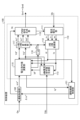
- FIG. 1 is a diagram showing a configuration example of a power conversion device 200 according to the first embodiment.
- FIG. 2 is a diagram showing a configuration example of an inverter 30 included in the power conversion device 200 according to the first embodiment.
- the power conversion device 200 is connected to a commercial power source 1 and a motor 7.
- the power conversion device 200 converts a first AC power of a power source voltage Vs supplied from the commercial power source 1 into a second AC power having a desired amplitude and phase, and supplies the second AC power to the motor 7.
- the power conversion device 200 includes a reactor 2, a rectifier 3, a smoothing capacitor 5, an inverter 30, a bus voltage detection unit 10, a load current detection unit 40, and a control device 100.
- the power conversion device 200 and the motor 7 constitute a motor drive device 400.
- the power conversion device 200, the motor 7, the outdoor fan 914, the outdoor heat exchanger 910, and the control unit 920 constitute a refrigeration cycle application device 900.
- the outdoor heat exchanger 910 exchanges heat between a refrigerant flowing therethrough and the outside air.
- the outdoor fan 914 sends air to the outdoor heat exchanger 910.
- the motor 7 drives and rotates the outdoor fan 914.
- Fig. 1 only the configuration of the refrigeration cycle application equipment 900 that is necessary for explaining the power conversion device 200 is shown. The detailed configuration of the refrigeration cycle application equipment 900 will be explained in the fourth embodiment.
- the reactor 2 is connected between the commercial power supply 1 and the rectifier 3.
- the rectifier 3 has a bridge circuit formed by rectifier elements 131 to 134, and rectifies and outputs the first AC power of the power supply voltage Vs supplied from the commercial power supply 1.
- the rectifier 3 performs full-wave rectification.
- the smoothing capacitor 5 is connected to the output terminal of the rectifier 3 and is a smoothing element that smoothes the power rectified by the rectifier 3.
- the smoothing capacitor 5 is, for example, an electrolytic capacitor, a film capacitor, or other capacitor.
- the smoothing capacitor 5 has a capacity to smooth the power rectified by the rectifier 3, and the voltage generated in the smoothing capacitor 5 by the smoothing is not a full-wave rectified waveform of the commercial power source 1, but a waveform in which a voltage ripple according to the frequency of the commercial power source 1 is superimposed on a DC component, and does not pulsate significantly.
- the frequency of this voltage ripple is twice the frequency of the power source voltage Vs when the commercial power source 1 is single-phase, and is mainly six times the frequency when the commercial power source 1 is three-phase.
- the bus voltage detection unit 10 is a detection unit that detects the voltage across the smoothing capacitor 5, i.e., the voltage between the DC buses 12a and 12b, as the bus voltage Vdc, and outputs the detected voltage value to the control device 100.
- the load current detection unit 40 is a detection unit that detects the load current Idc, which is a DC current flowing from the smoothing capacitor 5 to the inverter 30, and outputs the detected current value to the control device 100.
- the inverter 30 is connected to both ends of the smoothing capacitor 5, and converts the power output from the rectifier 3 and the smoothing capacitor 5 into a second AC power having a desired amplitude and phase, i.e., generates the second AC power and outputs it to the motor 7 that drives the load.
- the inverter 30 receives the bus voltage Vdc, generates a three-phase AC voltage with a variable frequency and voltage value, and supplies it to the motor 7 via output lines 331-333.
- the inverter 30 includes an inverter main circuit 310 and a drive circuit 350.
- the input terminals of the inverter main circuit 310 are connected to the DC buses 12a and 12b.
- the inverter main circuit 310 includes switching elements 311-316. Rectifier elements 321-326 for return current are connected in inverse parallel to each of the switching elements 311-316.
- the drive circuit 350 generates drive signals Sr1 to Sr6 based on PWM (Pulse Width Modulation) signals Sm1 to Sm6 output from the control device 100.
- the drive circuit 350 controls the on/off of the switching elements 311 to 316 using the drive signals Sr1 to Sr6. This enables the inverter 30 to supply a three-phase AC voltage with variable frequency and voltage to the motor 7 via the output lines 331 to 333.
- PWM signals Sm1 to Sm6 are signals with a logic circuit signal level, i.e., a magnitude of 0V to 5V.
- PWM signals Sm1 to Sm6 are signals with the ground potential of control device 100 as a reference potential.
- drive signals Sr1 to Sr6 are signals with a voltage level required to control switching elements 311 to 316, for example, a magnitude of -15V to +15V.
- Drive signals Sr1 to Sr6 are signals with a reference potential that is the potential of the negative terminal, i.e., the emitter terminal, of the corresponding switching elements 311 to 316.
- the motor 7 rotates according to the amplitude and phase of the second AC power supplied from the inverter 30.
- the motor 7 is used, for example, for the compression operation of the compressor and the rotation operation of the fan.
- the motor 7 drives and rotates the outdoor fan 914 provided in the refrigeration cycle application device 900 as the load described above, and sends air to the outdoor heat exchanger 910 to cool the outdoor heat exchanger 910.
- FIG. 1 shows the motor 7 with a Y-connection as the motor winding, this is just an example and is not limiting.
- the motor winding of the motor 7 may be a ⁇ -connection, or may be a specification that allows switching between a Y-connection and a ⁇ -connection.
- the arrangement of each component shown in FIG. 1 is one example, and the arrangement of each component is not limited to the example shown in FIG. 1.
- the reactor 2 may be arranged after the rectifier 3.
- the power conversion device 200 may include a boost unit, or the rectifier 3 may be given the function of a boost unit.
- the bus voltage detection unit 10 and the load current detection unit 40 may be collectively referred to as the detection unit.
- the voltage value detected by the bus voltage detection unit 10 and the current value detected by the load current detection unit 40 may be referred to as the detection value.
- the control device 100 obtains the bus voltage Vdc from the bus voltage detection unit 10 and the load current Idc from the load current detection unit 40.
- the control device 100 uses the detection values detected by each detection unit to control the operation of the inverter main circuit 310, specifically, the on/off of the switching elements 311 to 316 of the inverter main circuit 310.
- the control device 100 controls the rotation speed of the motor 7 by controlling the on/off of the switching elements 311 to 316 of the inverter main circuit 310.
- the rotation speed of the motor 7 may be expressed as the rotation speed of the motor 7.
- the control device 100 also calculates the load torque of the motor 7.
- the control device 100 does not need to use all the detection values obtained from each detection unit, and may perform control using some of the detection values. In this embodiment, the control device 100 performs control in a rotating coordinate system having a d-axis and a q-axis.
- FIG. 3 is a block diagram showing an example of the configuration of the control device 100 provided in the power conversion device 200 according to the first embodiment.
- the control device 100 includes an operation control unit 102, an inverter control unit 110, and an operation continuation control unit 121.
- the operation control unit 102 acquires command information Qe from the control unit 920 of the refrigeration cycle application device 900.
- the command information Qe is information based on, for example, a temperature detected by a temperature sensor (not shown), information indicating a set temperature instructed from a remote control (not shown), which is an operation unit, selection information of an operation mode, and instruction information for starting and ending operation.
- the operation mode is, for example, heating, cooling, dehumidification, etc.
- the operation control unit 102 also acquires a speed command reduction amount ⁇ * from the operation continuation control unit 121.
- the operation control unit 102 generates a frequency command value ⁇ e* for generating a voltage command value, which is a command value of a voltage to be applied to the motor 7, based on the command information Qe and the speed command reduction amount ⁇ * .
- the operation control unit 102 can obtain the frequency command value ⁇ e * by subtracting the speed command reduction amount ⁇ * from a value obtained by multiplying a rotational angular velocity command value ⁇ m *, which is a command value of the rotational speed of the motor 7, by the number of pole pairs Pm of the motor 7.
- the operation control unit 102 Based on the command information Qe, the operation control unit 102 generates a stop signal St which is a signal for stopping the operation of the inverter 30.
- the operation control unit 102 outputs the frequency command value ⁇ e * to the voltage command value calculation unit 115 of the inverter control unit 110, and outputs the stop signal St to the PWM signal generation unit 118 of the inverter control unit 110.
- the inverter control unit 110 includes a current restoration unit 111, a three-phase to two-phase conversion unit 112, a d-axis current command value generation unit 113, a voltage command value calculation unit 115, an electrical phase calculation unit 116, a two-phase to three-phase conversion unit 117, and a PWM signal generation unit 118.
- the current restoration unit 111 restores the phase currents iu, iv, and iw flowing through the motor 7 based on the load current Idc detected by the load current detection unit 40.
- the current restoration unit 111 can restore the phase currents iu, iv, and iw by sampling the load current Idc detected by the load current detection unit 40 at timing determined based on the PWM signals Sm1 to Sm6 generated by the PWM signal generation unit 118.
- the three-phase to two-phase conversion unit 112 converts the phase currents iu, iv, and iw restored by the current restoration unit 111 into a d-axis current id, which is an excitation current, and a q-axis current iq, which is a torque current, i.e., the current values of the d and q axes, using the electrical phase ⁇ e generated by the electrical phase calculation unit 116 described below.
- the d-axis current command value generating unit 113 generates a d-axis current command value Id * in the above-mentioned rotating coordinate system. Specifically, the d-axis current command value generating unit 113 obtains an optimal d-axis current command value Id* that is most efficient for driving the motor 7 based on the q-axis current iq, the bus voltage Vdc, the d-axis voltage command value Vd * , and the q-axis voltage command value Vq * .
- the d-axis current command value generating unit 113 outputs a d-axis current command value Id * that is a current phase ⁇ m at which the output torque of the motor 7 is equal to or greater than a specified value or is maximized, that is, the current value is equal to or less than a specified value or is minimized, based on the q-axis current iq , the bus voltage Vdc, the d-axis voltage command value Vd*, and the q-axis voltage command value Vq*.
- the d-axis current command value generating unit 113 obtains the d-axis current command value Id * based on the q-axis current iq , etc., but this is just an example and is not limited to this.
- the d-axis current command value generating unit 113 can obtain the same effect even if it determines the d-axis current command value Id * based on the d-axis current id, the frequency command value ⁇ e * , etc.
- the d-axis current command value generating unit 113 may determine the d-axis current command value Id * by flux-weakening control or the like.
- the voltage command value calculation unit 115 generates a d-axis voltage command value Vd * and a q-axis voltage command value Vq* based on the frequency command value ⁇ e * acquired from the operation control unit 102, the d-axis current id and the q-axis current iq acquired from the three-phase to two-phase conversion unit 112, and the d-axis current command value Id* acquired from the d-axis current command value generation unit 113. In addition, the voltage command value calculation unit 115 generates a q-axis current command value Iq* in the process of generating the d-axis voltage command value Vd * and the q-axis voltage command value Vq * .
- the voltage command value calculation unit 115 estimates a frequency estimated value ⁇ est based on the d-axis voltage command value Vd * , the q-axis voltage command value Vq * , the d-axis current id, and the q-axis current iq.
- the electrical phase calculation unit 116 calculates the electrical phase ⁇ e by integrating the frequency estimate ⁇ est obtained from the voltage command value calculation unit 115.
- the two-phase to three-phase conversion unit 117 converts the d-axis voltage command value Vd * and q-axis voltage command value Vq * obtained from the voltage command value calculation unit 115, i.e., the voltage command values in the two-phase coordinate system, into three-phase voltage command values Vu * , Vv * , Vw * , which are output voltage command values in the three-phase coordinate system, using the electrical phase ⁇ e obtained from the electrical phase calculation unit 116.
- the PWM signal generating unit 118 generates the PWM signals Sm1 to Sm6 based on the three-phase voltage command values Vu * , Vv * , Vw * acquired from the two-phase to three-phase conversion unit 117 and the stop signal St acquired from the operation control unit 102.
- the PWM signal generating unit 118 can also stop the motor 7 by not outputting the PWM signals Sm1 to Sm6 based on the stop signal St.
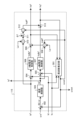
- FIG. 4 is a block diagram showing an example of the configuration of the voltage command value calculation unit 115 provided in the control device 100 of the power conversion device 200 according to the first embodiment.
- the voltage command value calculation unit 115 includes a frequency estimation unit 501, addition/subtraction units 502, 504, 505, 509, and 513, a speed control unit 503, a d-axis current control unit 506, a q-axis current control unit 507, multiplication units 508, 510, and 512, and an addition unit 511.
- a frequency estimation unit 501 estimates the frequency of the voltage supplied to the motor 7 based on the d-axis current id, the q-axis current iq, the d-axis voltage command value Vd * , and the q-axis voltage command value Vq * , and outputs the frequency estimation value ⁇ est.
- the frequency estimation value ⁇ est output from the frequency estimation unit 501 to the outside of the voltage command value calculation unit 115 in Fig. 4 is the frequency estimation value ⁇ est output from the voltage command value calculation unit 115 to the electrical phase calculation unit 116 in Fig. 3.
- An addition and subtraction unit 502 subtracts the frequency estimation value ⁇ est from the frequency command value ⁇ e * , and outputs a frequency deviation del_ ⁇ between the frequency command value ⁇ e * and the frequency estimation value ⁇ est.
- the speed control unit 503 calculates and outputs a q-axis current command value Iq * based on the frequency deviation del_ ⁇ .
- the q-axis current command value Iq * is a command value of the q-axis current iq at which the frequency deviation del_ ⁇ becomes zero, that is, a command value of the q-axis current iq for making the frequency command value ⁇ e * and the frequency estimated value ⁇ est coincide with each other.
- the speed control unit 503 is, for example, a proportional-integral (PI) controller, but is not limited to this.
- the speed control unit 503 outputs the q-axis current command value Iq * to the adder-subtractor unit 505 in the subsequent stage and also to the operation continuation control unit 121.
- the adder/subtracter 504 subtracts the d-axis current id from the d-axis current command value Id * and outputs the deviation between the d-axis current command value Id * and the d-axis current id.
- the d-axis current control unit 506 is, for example, configured with a PI controller, and operates to converge the deviation between the d-axis current command value Id * and the d-axis current id to zero.
- the d-axis current control unit 506 outputs a first d-axis voltage command value Vdfb * .
- the adder/subtracter 505 subtracts the q-axis current iq from the q-axis current command value Iq * and outputs the deviation between the q-axis current command value Iq * and the q-axis current iq.
- the q-axis current control unit 507 is, for example, configured with a PI controller, and operates to converge the deviation between the q-axis current command value Iq * and the q-axis current iq to zero.
- the q-axis current control unit 507 outputs a first q-axis voltage command value Vqfb * .
- the multiplier 508 multiplies the q-axis current command value Iq * by the q-axis inductance Lq of the motor 7 and the frequency estimate value ⁇ est to calculate and output a compensation value Vdff * of the first d-axis voltage command value Vdfb * .
- the adder/subtracter 509 subtracts the compensation value Vdff * from the first d-axis voltage command value Vdfb * and outputs a second d-axis voltage command value which is the deviation (Vdfb * -Vdff * ) between the first d-axis voltage command value Vdfb * and the compensation value Vdff * as the d-axis voltage command value Vd * from the voltage command value calculator 115.
- the multiplier 510 multiplies the d-axis current command value Id * by the d-axis inductance Ld of the motor 7 and outputs the result.
- the adder 511 adds the magnetic flux linkage vector ⁇ f of the motor 7 to the output from the multiplier 510.
- the multiplier 512 multiplies the output from the adder 511 by the frequency estimate value ⁇ est to calculate and output a compensation value Vqff * of the first q-axis voltage command value Vqfb * .
- the adder/subtracter 513 subtracts the compensation value Vqff* from the first q-axis voltage command value Vqfb * and outputs a second q-axis voltage command value, which is the deviation (Vqfb * -Vqff * ) between the first q-axis voltage command value Vqfb* and the compensation value Vqff * , as the q-axis voltage command value Vq * from the voltage command value calculator 115.
- the operation continuation control unit 121 calculates a speed command reduction amount ⁇ * based on the d-axis current id acquired from the three-phase to two-phase conversion unit 112 and the q-axis current command value Iq * acquired from the voltage command value calculation unit 115.
- the operation continuation control unit 121 outputs the calculated speed command reduction amount ⁇ * to the operation control unit 102.
- the control device 100 controls the speed command value to be reduced so that the difference between the rotation speed and the speed command value for controlling the rotation speed is within a specified range.
- the control device 100 controls the motor 7 to rotate at a reduced rotation speed in a frosted state with a load torque equivalent to the load torque that can be output in a frost-free state.
- the control device 100 can calculate the load torque, i.e., the estimated load torque Tm, using the current value detected by the load current detection unit 40 and parameters based on the specifications of the motor 7. Specifically, the control device 100 estimates the load torque of the motor 7, i.e., calculates the estimated load torque Tm of the motor 7, using the d-axis current id and q-axis current iq output from the three-phase to two-phase conversion unit 112. The control device 100 calculates the estimated load torque Tm of the motor 7 based on the following equation (1).
- Tm Pm ⁇ aiq + Pm(Ld-Lq)idiq ... (1)
- Tm is the estimated load torque
- Pm is the number of pole pairs of the motor 7
- ⁇ a is the induced voltage constant of the motor 7
- Ld is the d-axis inductance of the motor 7
- Lq is the q-axis inductance of the motor 7
- id is the d-axis current
- iq is the q-axis current.
- the control device 100 obtains the d-axis current id and the q-axis current iq from the three-phase to two-phase conversion unit 112, but stores the number of pole pairs Pm of the motor 7, the induced voltage constant ⁇ a of the motor 7, the d-axis inductance Ld of the motor 7, and the q-axis inductance Lq of the motor 7 in advance.
- FIG. 5 is a diagram showing the characteristics of the rotation speed of the motor 7 and the load torque of the motor 7 when the power conversion device 200 according to embodiment 1 is mounted on the refrigeration cycle application device 900.
- the horizontal axis indicates the rotation speed of the motor 7
- the vertical axis indicates the load torque of the motor 7.
- the solid line on which circles are plotted indicates a polynomial that represents a state when frost does not occur in the refrigeration cycle application device 900
- the dashed line on which squares are plotted indicates a polynomial that represents a state when frost occurs in the refrigeration cycle application device 900.
- the rotation speed of the motor 7 on the horizontal axis may be the rotation speed of the outdoor fan 914.
- the load torque is larger when frost occurs in the refrigeration cycle application device 900 than when frost does not occur in the refrigeration cycle application device 900.
- the higher the rotation speed of the motor 7, the larger the difference between the load torque when frost has formed in the refrigeration cycle application device 900 and the load torque when frost has not formed in the refrigeration cycle application device 900.
- the control device 100 reduces the rotation speed of the motor 7 to about 1400 rpm, thereby making it possible to keep the output load torque at the same level while continuing the rotation, i.e., operation, of the motor 7.
- FIG. 6 is a block diagram showing an example of the configuration of the operation continuation control unit 121 provided in the control device 100 of the power conversion device 200 according to embodiment 1.
- the operation continuation control unit 121 includes a limiter value calculation unit 141, an addition/subtraction unit 142, a deviation code processing unit 143, and an output unit 144.
- the limiter value calculation unit 141 uses the d-axis current id acquired from the three-phase to two-phase conversion unit 112 to calculate a limiter value to be compared with the q-axis current command value iq * in the addition/subtraction unit 142.
- the limiter value calculation unit 141 calculates the limiter value iq_lim based on the following equation (2).
- iq_lim ⁇ (3Ie 2 - id 2 ) ... (2)
- iq_lim is a limiter value
- Ie is a limiter value of the effective value of the phase current
- id is a d-axis current indicating the current d-axis current value obtainable from the 3-phase to 2-phase conversion unit 112.
- ⁇ (3Ie 2 - id 2 ) represents the square root of (3Ie 2 - id 2 ).
- the limiter value iq_lim indicates the magnitude of a current that can be circulated as the q-axis current iq, which is the remainder obtained by subtracting the d-axis current id from the limiter value Ie of the effective value of the phase current, in order to preferentially pass the d-axis current id.
- the limiter value calculation unit 141 outputs the limiter value iq_lim calculated by calculation to the addition and subtraction unit 142.
- the adding/subtracting unit 142 obtains the limiter value iq_lim from the limiter value calculation unit 141, and obtains the q-axis current command value iq * from the voltage command value calculation unit 115.
- the adding/subtracting unit 142 calculates the deviation between the limiter value iq_lim and the q-axis current command value iq * by subtracting the q-axis current command value iq * from the limiter value iq_lim.
- the adding/subtracting unit 142 outputs the deviation between the limiter value iq_lim and the q-axis current command value iq * obtained by the calculation to the deviation sign processing unit 143.
- the deviation sign processing unit 143 When the deviation between the limiter value iq_lim and the q-axis current command value iq * is less than 0, i.e., when the q-axis current command value iq * is greater than the limiter value iq_lim, the deviation sign processing unit 143 performs control so that a value obtained by performing integral control on the deviation between the limiter value iq_lim and the q-axis current command value iq * using K Iac /S is output as the speed command decrease amount ⁇ * from the output unit 144.
- K Iac is the integral gain of the integral control
- S in the denominator of K Iac /S represents the Laplace operator.
- the control device 100 reduces the q-axis current command value Iq * by an amount that the q-axis current command value Iq * exceeds the limiter value iq_lim, which is the q-axis current limiter value of the q-axis current command value Iq * , which is the speed command value.
- the control device 100 sets the limiter value iq_lim, which is the q-axis current limiter value, based on the limiter value Ie of the effective value of the phase current, which is the current of each phase flowing from the power conversion device 200 to the motor 7, and the d-axis current id, which is the current d-axis current value.
- the control device 100 can keep the output load torque at the same level by setting the rotation speed of the motor 7 to about 1400 rpm, thereby allowing the motor 7 to continue rotating, i.e., to continue operating. In other words, even if an event occurs in which the load torque of the motor 7 becomes large, the control device 100 controls the rotation of the motor 7 while maintaining the maximum current in the power conversion device 200 by controlling the rotation speed of the motor 7 to be reduced by the amount that exceeds the limiter value iq_lim.
- the method by which the limiter value calculation unit 141 calculates the limiter value iq_lim is not limited to the example of equation (2). As long as the rotation of the motor 7 can be controlled while maintaining the maximum current in the power conversion device 200, the limiter value iq_lim calculated by the limiter value calculation unit 141 may be calculated by another method. For example, the limiter value calculation unit 141 may calculate the limiter value iq_lim from the perspective of voltage saturation.
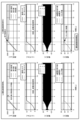
- FIG. 7 is a diagram showing the difference in characteristics depending on whether or not the control of continuous operation is performed by the operation continuation control unit 121 of the control device 100 provided in the power conversion device 200 according to the first embodiment.
- the left side shows the case where the operation continuation control by the operation continuation control unit 121 is not performed
- the right side shows the case where the operation continuation control by the operation continuation control unit 121 is performed.
- the first row of FIG. 7 shows the rotation speed of the motor 7
- the second row of FIG. 7 shows the torque of the motor 7
- the third row of FIG. 7 shows the phase currents iu, iv, and iw of the motor 7, and the fourth row of FIG.
- the first graph on the left side of FIG. 7 shows a state where the command value and the estimated speed and actual speed are separated. This shows a state where the power conversion device 200 tries to rotate the motor 7 with constant torque control or maximum torque, but the torque required to rotate the motor 7 increases due to the effects of frosting, etc., and the desired rotation speed, i.e., the rotation speed indicated by the command value, cannot be achieved. If the command value and the estimated speed and actual speed continue to diverge, the control is likely to become unstable, such as causing a wind-up phenomenon, which is not preferable for control by the control device 100.
- the command value decreases after a specified time has elapsed since the start of continuous operation control, and the state where the command value and the estimated speed and actual speed are separated is resolved in the first graph on the right side of FIG. 7. This allows the control device 100 to avoid a situation where the command value and the estimated speed and actual speed continue to diverge, and to achieve a stable control state.
- FIG. 8 is a flowchart showing the operation of the power conversion device 200 according to the first embodiment.
- the operation continuation control unit 121 of the control device 100 calculates a limiter value iq_lim for the q-axis current command value Iq* (step S1).
- the operation continuation control unit 121 calculates the deviation between the limiter value iq_lim and the q-axis current command value iq * acquired from the voltage command value calculation unit 115 (step S2).
- the operation continuation control unit 121 outputs a value obtained by performing integral control of the deviation between the limiter value iq_lim and the q-axis current command value iq * using K Iac /S as the speed command reduction amount ⁇ * to the operation control unit 102 (step S5).
- the case where the q-axis current command value Iq * is limited by the limiter value iq_lim in the operation continuation control unit 121 of the control device 100 includes, but is not limited to, the case where the load torque of the motor 7 simply increases and the q-axis current command value Iq * is limited by the limiter value iq_lim, as described above.
- the case where the q-axis current command value Iq * is limited by the limiter value iq_lim in the operation continuation control unit 121 of the control device 100 includes, for example, a case where the speed decreases after the control device 100 has completed the flux-weakening control to the limit, causing a deviation in the input of the speed control unit 503, and the q-axis current command value Iq * increases to the point where it is limited by the limiter value iq_lim.
- FIG. 9 is a diagram showing an example of a hardware configuration realizing the control device 100 included in the power conversion device 200 according to the first embodiment.
- the control device 100 is realized by a processor 91 and a memory 92.
- the processor 91 is a CPU (Central Processing Unit, also known as a central processing unit, processing unit, arithmetic unit, microprocessor, microcomputer, processor, or DSP (Digital Signal Processor)) or a system LSI (Large Scale Integration).
- Examples of memory 92 include non-volatile or volatile semiconductor memory such as RAM (Random Access Memory), ROM (Read Only Memory), flash memory, EPROM (Erasable Programmable Read Only Memory), and EEPROM (registered trademark) (Electrically Erasable Programmable Read Only Memory).
- Memory 92 is not limited to these, and may also be a magnetic disk, optical disk, compact disk, mini disk, or DVD (Digital Versatile Disc).
- the operation continuation control unit 121 of the control device 100 outputs a value obtained by performing integral control using K Iac /S on the deviation between the limiter value iq_lim and the q-axis current command value iq * as the speed command reduction amount ⁇ * to the operation control unit 102.
- the operation control unit 102 outputs a value obtained by reducing the frequency command value obtained by calculation by the speed command reduction amount ⁇ * to the voltage command value calculation unit 115 as the frequency command value ⁇ e * .
- the control device 100 controls the motor 7 to reduce the rotation speed by the amount that exceeds the limiter value iq_lim, thereby allowing the motor 7 to continue rotating while maintaining the maximum current in the power conversion device 200. Even when the load torque of the motor 7 connected to the power conversion device 200 increases, the control device 100 can continue to operate the motor 7 while suppressing a decrease in the rotation speed of the motor 7 .
- the motor 7 targeted by the control device 100 is a fan motor that rotates the outdoor fan 914, but the present invention is not limited to this.
- the control device 100 can also perform similar control on motors 7 other than fan motors, as long as a similar event that increases the load torque occurs.
- Embodiment 2 the operation continuation control unit 121 starts the operation continuation control when the q-axis current command value Iq * acquired from the voltage command value calculation unit 115 becomes larger than the limiter value iq_lim.
- the operation continuation control unit 121 starts the operation continuation control when the q-axis current command value Iq * acquired from the voltage command value calculation unit 115 becomes larger than the limiter value iq_lim.
- another timing at which the operation continuation control unit 121 starts the operation continuation control will be described.
- the operation continuation control unit 121 may start operation continuation control when the estimated speed of the motor 7 becomes smaller than the speed command value for the motor 7. When the estimated speed of the motor 7 becomes smaller than the speed command value for the motor 7, this is the state shown in the first graph on the left side of Figure 7.
- the operation continuation control unit 121 can achieve the same effect as in embodiment 1 by determining whether or not to perform operation continuation control using the estimated speed of the motor 7 and the speed command value for the motor 7.
- the operation continuation control unit 121 may start the operation continuation control when the first condition or the second condition continues for a specified period, assuming that the q-axis current command value Iq * and the limiter value iq_lim are used as the first condition, and the above-mentioned estimated speed of the motor 7 and the speed command value for the motor 7 are used as the second condition. Such a case is assumed to be a third condition.
- the motor 7 may temporarily be in the state of the first condition or the second condition by accelerating or decelerating even during normal control by the power conversion device 200.
- the operation continuation control unit 121 may determine to start the operation continuation control when the period in which the first condition or the second condition is satisfied continues for a specified period, as in the third condition. That is, the operation continuation control unit 121 can reduce the speed command value when a first condition is satisfied in which the speed command value is limited by a specified limiter value iq_lim, or when a second condition is satisfied in which the rotation speed of the motor 7 is smaller than the speed command value, or when a third condition is satisfied in which the first condition or the second condition continues for a specified period. It can also be said that the operation continuation control unit 121 reduces the speed command value when it becomes impossible to control the rotation speed of the motor 7 to follow the speed command value.
- the continuous operation control unit 121 can stop the continuous operation control when any of the requirements of the first condition, the second condition, or the third condition is no longer satisfied.
- the continuous operation control unit 121 may determine when to start the continuous operation control and when to stop the continuous operation control based on different values.
- the operation continuation control unit 121 can use several conditions to make a decision when to start operation continuation control.
- the operation continuation control unit 121 can also use several conditions to make a decision when to stop operation continuation control.
- Embodiment 3 In the third embodiment, a case will be described in which the calculation process in the speed control unit 503 of the voltage command value calculation unit 115 is changed by the operation continuation control of the operation continuation control unit 121.
- FIG. 10 is a diagram showing an image of the calculation process in the power conversion device 200 according to the third embodiment.
- FIG. 10 shows a part of the calculation process in the power conversion device 200 and a flow of calculation of the part.
- the limiter value indicates the limiter value iq_lim calculated by the limiter value calculation unit 141
- the next addition and subtraction process indicates the process of the addition and subtraction unit 142
- the next speed drooping control indicates the integral control by K Iac /S in the output unit 144
- the next addition process indicates the internal process of the voltage command value calculation unit 115
- the next speed control indicates the calculation process in the speed control unit 503.
- the speed control unit 503 may calculate the q-axis current command value Iq * only by proportional control, as shown in the lower part of FIG. 10, that is, the speed control when calculating the q-axis current command value Iq * may be performed by proportional control.
- the integral gain K Iac of the integral control in the operation continuation control unit 121 described in the first embodiment can be expressed as in equation (3).
- K Iac ( ⁇ ac / ⁇ sc) ⁇ ( Pm2 ⁇ ⁇ a / J) ... (3)
- ⁇ ac is the control response in the speed control unit 503
- ⁇ sc is the control response in the operation continuation control unit 121
- Pm is the number of pole pairs of the motor 7
- ⁇ a is the induced voltage constant of the motor 7
- J is the inertia of the motor 7.
- control device 100 can change the calculation formula etc. as appropriate depending on the control state.
- FIG. 11 is a diagram showing a configuration example of a refrigeration cycle-applied device 900 according to embodiment 4.
- the refrigeration cycle-applied device 900 according to embodiment 4 includes a power conversion device 200.
- the refrigeration cycle-applied device 900 according to embodiment 4 can be applied to products including a refrigeration cycle, such as air conditioners, refrigerators, freezers, and heat pump water heaters.
- a refrigeration cycle such as air conditioners, refrigerators, freezers, and heat pump water heaters.
- components having the same functions as those in embodiment 1 are denoted by the same reference numerals as those in embodiment 1.
- the refrigeration cycle application device 900 includes a motor 7a similar to the motor 7 in the first embodiment, and an outdoor fan 914.
- the motor 7a drives the outdoor fan 914 to rotate.
- the outdoor fan 914 blows air to the outdoor heat exchanger 910.
- the outdoor heat exchanger 910 exchanges heat between the refrigerant flowing therethrough and the air.
- the refrigeration cycle application device 900 also includes a compressor 8 incorporating a motor 7b similar to the motor 7 in the first embodiment, a four-way valve 902, an indoor heat exchanger 906, an expansion valve 908, and an outdoor heat exchanger 910, which are attached via refrigerant piping 912.
- the refrigeration cycle device 900 can perform heating or cooling operation by switching the four-way valve 902.
- the compression mechanism 904 is driven by a variable speed controlled motor 7b.
- the refrigerant is pressurized by the compression mechanism 904 and sent out, passes through the four-way valve 902, the indoor heat exchanger 906, the expansion valve 908, the outdoor heat exchanger 910, and the four-way valve 902, and returns to the compression mechanism 904.
- the refrigerant is pressurized by the compression mechanism 904 and sent out, passes through the four-way valve 902, the outdoor heat exchanger 910, the expansion valve 908, the indoor heat exchanger 906, and the four-way valve 902, and returns to the compression mechanism 904.
- the indoor heat exchanger 906 acts as a condenser to release heat, and the outdoor heat exchanger 910 acts as an evaporator to absorb heat.
- the outdoor heat exchanger 910 acts as a condenser to release heat, and the indoor heat exchanger 906 acts as an evaporator to absorb heat.
- the expansion valve 908 reduces the pressure of the refrigerant to expand it.
Landscapes
- Engineering & Computer Science (AREA)
- Power Engineering (AREA)
- Control Of Ac Motors In General (AREA)
Abstract
電力変換装置(200)は、商用電源(1)から供給される第1の交流電力を整流する整流部(3)と、整流部(3)の出力端に接続される平滑コンデンサ(5)と、平滑コンデンサ(5)の両端に接続され、第2の交流電力を生成して負荷を駆動するモータ(7)に出力するインバータ(30)と、インバータ(30)の動作を制御してモータ(7)の回転速度を制御する制御装置(100)と、を備え、制御装置(100)は、モータ(7)の回転速度が低下したときに回転速度と回転速度を制御するための速度指令値との差分が規定された範囲内になるように速度指令値を低減させる。
Description
本開示は、交流電力を所望の電力に変換する電力変換装置、モータ駆動装置および冷凍サイクル適用機器に関する。
従来、一般的なファンモータ制御は、速度指令に追従するように、負荷トルクが大きくなると、負荷トルクに合わせて電流を大きく流すように制御している。空気調和機などに搭載される電力変換装置のファンモータ制御は、着霜などによって想定外の負荷トルクの大きさとなった場合でも、速度が落ちないようにするため、すなわち設定している速度指令に追従するように、負荷トルクに合わせて電流を大きく流すように制御する。しかしながら、このようなファンモータ制御は、負荷トルクが想定外に大きくなり、負荷トルクに合わせて電流を大きく流すことによって過電流になると、ファンモータの運転が停止し、ファンモータを継続して運転することが出来ないことから、快適性、省エネ性などの面において好ましくない。
このような問題に対して、特許文献1には、モータの出力可能なトルク最大値よりも過大なトルク指令値が要求された場合、q軸の電流指令値がリミッタ値まで増加しないように、速度制御の入力を制限する技術が開示されている。
しかしながら、上記従来の技術によれば、単純に速度指令の入力を制限するような制御を行うと、必要以上にファンモータの回転速度が低下してしまう可能性がある、という問題があった。
本開示は、上記に鑑みてなされたものであって、接続されるモータの負荷トルクが大きくなった場合でも、モータの回転速度の低下を抑制しつつモータの運転を継続可能な電力変換装置を得ることを目的とする。
上述した課題を解決し、目的を達成するために、本開示に係る電力変換装置は、商用電源から供給される第1の交流電力を整流する整流部と、整流部の出力端に接続されるコンデンサと、コンデンサの両端に接続され、第2の交流電力を生成して負荷を駆動するモータに出力するインバータと、インバータの動作を制御してモータの回転速度を制御する制御装置と、を備える。制御装置は、モータの回転速度が低下したときに回転速度と回転速度を制御するための速度指令値との差分が規定された範囲内になるように速度指令値を低減させる。
本開示に係る電力変換装置は、接続されるモータの負荷トルクが大きくなった場合でも、モータの回転速度の低下を抑制しつつモータの運転を継続可能である、という効果を奏する。
以下に、本開示の実施の形態に係る電力変換装置、モータ駆動装置および冷凍サイクル適用機器を図面に基づいて詳細に説明する。
実施の形態1.
図1は、実施の形態1に係る電力変換装置200の構成例を示す図である。図2は、実施の形態1に係る電力変換装置200が備えるインバータ30の構成例を示す図である。電力変換装置200は、商用電源1およびモータ7に接続される。電力変換装置200は、商用電源1から供給される電源電圧Vsの第1の交流電力を所望の振幅および位相を有する第2の交流電力に変換し、モータ7に供給する。電力変換装置200は、リアクタ2と、整流部3と、平滑コンデンサ5と、インバータ30と、母線電圧検出部10と、負荷電流検出部40と、制御装置100と、を備える。なお、電力変換装置200およびモータ7によって、モータ駆動装置400を構成している。また、電力変換装置200、モータ7、室外ファン914、室外熱交換器910、および制御部920によって、冷凍サイクル適用機器900を構成している。室外熱交換器910は、内部を流れる冷媒と外部の空気とで熱交換を行う。室外ファン914は、室外熱交換器910に送風する。モータ7は、室外ファン914を回転駆動させる。図1では、冷凍サイクル適用機器900のうち、電力変換装置200の説明で必要な構成のみを示している。冷凍サイクル適用機器900の詳細な構成については実施の形態4で説明する。
図1は、実施の形態1に係る電力変換装置200の構成例を示す図である。図2は、実施の形態1に係る電力変換装置200が備えるインバータ30の構成例を示す図である。電力変換装置200は、商用電源1およびモータ7に接続される。電力変換装置200は、商用電源1から供給される電源電圧Vsの第1の交流電力を所望の振幅および位相を有する第2の交流電力に変換し、モータ7に供給する。電力変換装置200は、リアクタ2と、整流部3と、平滑コンデンサ5と、インバータ30と、母線電圧検出部10と、負荷電流検出部40と、制御装置100と、を備える。なお、電力変換装置200およびモータ7によって、モータ駆動装置400を構成している。また、電力変換装置200、モータ7、室外ファン914、室外熱交換器910、および制御部920によって、冷凍サイクル適用機器900を構成している。室外熱交換器910は、内部を流れる冷媒と外部の空気とで熱交換を行う。室外ファン914は、室外熱交換器910に送風する。モータ7は、室外ファン914を回転駆動させる。図1では、冷凍サイクル適用機器900のうち、電力変換装置200の説明で必要な構成のみを示している。冷凍サイクル適用機器900の詳細な構成については実施の形態4で説明する。
リアクタ2は、商用電源1と整流部3との間に接続される。整流部3は、整流素子131~134によって構成されるブリッジ回路を有し、商用電源1から供給される電源電圧Vsの第1の交流電力を整流して出力する。整流部3は、全波整流を行うものである。
平滑コンデンサ5は、整流部3の出力端に接続され、整流部3によって整流された電力を平滑化する平滑素子である。平滑コンデンサ5は、例えば、電解コンデンサ、フィルムコンデンサなどのコンデンサである。平滑コンデンサ5は、整流部3によって整流された電力を平滑化するような容量を有し、平滑化により平滑コンデンサ5に発生する電圧は商用電源1の全波整流波形形状ではなく、直流成分に商用電源1の周波数に応じた電圧リプルが重畳した波形形状となり、大きく脈動しない。この電圧リプルの周波数は、商用電源1が単相の場合は電源電圧Vsの周波数の2倍成分となり、商用電源1が三相の場合は6倍成分が主成分となる。
母線電圧検出部10は、平滑コンデンサ5の両端電圧、すなわち直流母線12a,12b間の電圧を母線電圧Vdcとして検出し、検出した電圧値を制御装置100に出力する検出部である。負荷電流検出部40は、平滑コンデンサ5からインバータ30に流入される直流電流である負荷電流Idcを検出し、検出した電流値を制御装置100に出力する検出部である。
インバータ30は、平滑コンデンサ5の両端に接続され、整流部3および平滑コンデンサ5から出力される電力を所望の振幅および位相を有する第2の交流電力に変換、すなわち第2の交流電力を生成して、負荷を駆動するモータ7に出力する。具体的には、インバータ30は、母線電圧Vdcを受けて、周波数および電圧値が可変の3相交流電圧を発生して、出力線331~333を介してモータ7に供給する。インバータ30は、図2に示すように、インバータ主回路310と、駆動回路350と、を備える。インバータ主回路310の入力端子は、直流母線12a,12bに接続されている。インバータ主回路310は、スイッチング素子311~316を備える。スイッチング素子311~316の各々には、還流用の整流素子321~326が逆並列接続されている。
駆動回路350は、制御装置100から出力されるPWM(Pulse Width Modulation)信号Sm1~Sm6に基づいて、駆動信号Sr1~Sr6を生成する。駆動回路350は、駆動信号Sr1~Sr6によってスイッチング素子311~316のオンオフを制御する。これにより、インバータ30は、周波数可変かつ電圧可変の3相交流電圧を、出力線331~333を介してモータ7に供給することができる。
PWM信号Sm1~Sm6は、論理回路の信号レベル、すなわち0V~5Vの大きさを持つ信号である。PWM信号Sm1~Sm6は、制御装置100の接地電位を基準電位とする信号である。一方、駆動信号Sr1~Sr6は、スイッチング素子311~316を制御するのに必要な電圧レベル、例えば、-15V~+15Vの大きさを持つ信号である。駆動信号Sr1~Sr6は、それぞれ対応するスイッチング素子311~316の負側の端子、すなわちエミッタ端子の電位を基準電位とする信号である。
モータ7は、インバータ30から供給される第2の交流電力の振幅および位相に応じて回転する。モータ7は、例えば、圧縮機での圧縮動作、ファンの回転動作などに使用される。モータ7は、図1の例では、前述の負荷として、冷凍サイクル適用機器900が備える室外ファン914を回転駆動させ、室外熱交換器910に風を送って室外熱交換器910の冷却などを行う。モータ7について、図1ではモータ巻線がY結線の場合を示しているが、一例であり、これに限定されない。モータ7のモータ巻線は、Δ結線であってもよいし、Y結線とΔ結線とが切り替え可能な仕様であってもよい。
なお、電力変換装置200において、図1に示す各構成の配置は一例であり、各構成の配置は図1で示される例に限定されない。例えば、リアクタ2は、整流部3の後段に配置されてもよい。また、電力変換装置200は、昇圧部を備えてもよいし、整流部3に昇圧部の機能を持たせるようにしてもよい。以降の説明において、母線電圧検出部10、および負荷電流検出部40をまとめて検出部と称することがある。また、母線電圧検出部10で検出された電圧値、および負荷電流検出部40で検出された電流値を、検出値と称することがある。
制御装置100は、母線電圧検出部10から母線電圧Vdcを取得し、負荷電流検出部40から負荷電流Idcを取得する。制御装置100は、各検出部によって検出された検出値を用いて、インバータ主回路310の動作、具体的には、インバータ主回路310が有するスイッチング素子311~316のオンオフを制御する。制御装置100は、インバータ主回路310が有するスイッチング素子311~316のオンオフを制御することで、モータ7の回転数を制御する。なお、モータ7の回転数については、モータ7の回転速度と表記してもよい。以降についても同様とする。また、制御装置100は、モータ7の負荷トルクを演算する。なお、制御装置100は、各検出部から取得した全ての検出値を用いなくてもよく、一部の検出値を用いて制御を行ってもよい。本実施の形態において、制御装置100は、d軸およびq軸を有する回転座標系において制御を行う。
制御装置100の詳細な構成および動作について説明する。図3は、実施の形態1に係る電力変換装置200が備える制御装置100の構成例を示すブロック図である。制御装置100は、運転制御部102と、インバータ制御部110と、運転継続制御部121と、を備える。
運転制御部102は、冷凍サイクル適用機器900の制御部920から指令情報Qeを取得する。冷凍サイクル適用機器900が空気調和機である場合、指令情報Qeは、例えば、図示しない温度センサで検出された温度、図示しない操作部であるリモコンから指示される設定温度を示す情報、運転モードの選択情報、運転開始及び運転終了の指示情報などに基づく情報である。運転モードとは、例えば、暖房、冷房、除湿などである。また、運転制御部102は、運転継続制御部121から速度指令低下量Δω*を取得する。運転制御部102は、指令情報Qeおよび速度指令低下量Δω*に基づいて、モータ7に印加する電圧の指令値である電圧指令値を生成するための周波数指令値ωe*を生成する。運転制御部102は、周波数指令値ωe*について、モータ7の回転速度の指令値である回転角速度指令値ωm*にモータ7の極対数Pmを乗算した値から速度指令低下量Δω*を減算することで求めることができる。また、運転制御部102は、指令情報Qeに基づいて、インバータ30の動作を停止するための信号である停止信号Stを生成する。運転制御部102は、周波数指令値ωe*をインバータ制御部110の電圧指令値演算部115に出力し、停止信号Stをインバータ制御部110のPWM信号生成部118に出力する。
インバータ制御部110は、電流復元部111と、3相2相変換部112と、d軸電流指令値生成部113と、電圧指令値演算部115と、電気位相演算部116と、2相3相変換部117と、PWM信号生成部118と、を備える。
電流復元部111は、負荷電流検出部40で検出された負荷電流Idcに基づいてモータ7に流れる相電流iu,iv,iwを復元する。電流復元部111は、負荷電流検出部40で検出された負荷電流Idcを、PWM信号生成部118で生成されたPWM信号Sm1~Sm6に基づいて定められるタイミングでサンプリングすることによって、相電流iu,iv,iwを復元することができる。
3相2相変換部112は、電流復元部111で復元された相電流iu,iv,iwを、後述する電気位相演算部116で生成された電気位相θeを用いて、励磁電流であるd軸電流id、およびトルク電流であるq軸電流iq、すなわちdq軸の電流値に変換する。
d軸電流指令値生成部113は、前述の回転座標系におけるd軸電流指令値Id*を生成する。具体的には、d軸電流指令値生成部113は、q軸電流iqと、母線電圧Vdcと、d軸電圧指令値Vd*と、q軸電圧指令値Vq*とに基づいて、モータ7を駆動するために最も効率が良くなる最適なd軸電流指令値Id*を求める。d軸電流指令値生成部113は、q軸電流iq、母線電圧Vdc、d軸電圧指令値Vd*、およびq軸電圧指令値Vq*に基づいて、モータ7の出力トルクが規定された値以上または最大になる、すなわち電流値が規定された値以下または最小になる電流位相βmとなるd軸電流指令値Id*を出力する。なお、ここでは、d軸電流指令値生成部113が、q軸電流iqなどに基づいてd軸電流指令値Id*を求めているが、一例であり、これに限定されない。d軸電流指令値生成部113は、d軸電流id、周波数指令値ωe*などに基づいてd軸電流指令値Id*を求めても、同様の効果を得ることができる。また、d軸電流指令値生成部113は、弱め磁束制御などによってd軸電流指令値Id*を決定してもよい。
電圧指令値演算部115は、運転制御部102から取得した周波数指令値ωe*と、3相2相変換部112から取得したd軸電流idおよびq軸電流iqと、d軸電流指令値生成部113から取得したd軸電流指令値Id*とに基づいて、d軸電圧指令値Vd*およびq軸電圧指令値Vq*を生成する。また、電圧指令値演算部115は、d軸電圧指令値Vd*およびq軸電圧指令値Vq*を生成する過程において、q軸電流指令値Iq*を生成する。さらに、電圧指令値演算部115は、d軸電圧指令値Vd*と、q軸電圧指令値Vq*と、d軸電流idと、q軸電流iqとに基づいて、周波数推定値ωestを推定する。
電気位相演算部116は、電圧指令値演算部115から取得した周波数推定値ωestを積分することで、電気位相θeを演算する。
2相3相変換部117は、電圧指令値演算部115から取得したd軸電圧指令値Vd*およびq軸電圧指令値Vq*、すなわち2相座標系の電圧指令値を、電気位相演算部116から取得した電気位相θeを用いて、3相座標系の出力電圧指令値である3相電圧指令値Vu*,Vv*,Vw*に変換する。
PWM信号生成部118は、2相3相変換部117から取得した3相電圧指令値Vu*,Vv*,Vw*と、運転制御部102から取得した停止信号Stとに基づいて、PWM信号Sm1~Sm6を生成する。PWM信号生成部118は、停止信号Stに基づいてPWM信号Sm1~Sm6を出力しないようにすることによって、モータ7を停止することも可能である。
電圧指令値演算部115の構成および動作について詳細に説明する。図4は、実施の形態1に係る電力変換装置200の制御装置100が備える電圧指令値演算部115の構成例を示すブロック図である。電圧指令値演算部115は、周波数推定部501と、加減算部502,504,505,509,513と、速度制御部503と、d軸電流制御部506と、q軸電流制御部507と、乗算部508,510,512と、加算部511と、を備える。
周波数推定部501は、d軸電流idと、q軸電流iqと、d軸電圧指令値Vd*と、q軸電圧指令値Vq*とに基づいて、モータ7に供給される電圧の周波数を推定し、周波数推定値ωestとして出力する。なお、図4において周波数推定部501から電圧指令値演算部115の外部に出力される周波数推定値ωestは、図3において電圧指令値演算部115から電気位相演算部116に出力される周波数推定値ωestである。加減算部502は、周波数指令値ωe*から周波数推定値ωestを減算し、周波数指令値ωe*と周波数推定値ωestとの周波数偏差del_ωを出力する。
速度制御部503は、周波数偏差del_ωに基づいて、q軸電流指令値Iq*を演算して出力する。q軸電流指令値Iq*は、周波数偏差del_ωが零となるq軸電流iqの指令値、すなわち、周波数指令値ωe*と周波数推定値ωestとを一致させるためのq軸電流iqの指令値である。速度制御部503は、例えば、比例積分(Proportional-Integral:PI)制御器であるが、これに限定されない。速度制御部503は、q軸電流指令値Iq*を、後段の加減算部505に出力するとともに、運転継続制御部121に出力する。
加減算部504は、d軸電流指令値Id*からd軸電流idを減算し、d軸電流指令値Id*とd軸電流idとの偏差を出力する。d軸電流制御部506は、例えば、PI制御器で構成され、d軸電流指令値Id*とd軸電流idとの偏差を零に収束させるように動作する。d軸電流制御部506は、第1のd軸電圧指令値Vdfb*を出力する。
加減算部505は、q軸電流指令値Iq*からq軸電流iqを減算し、q軸電流指令値Iq*とq軸電流iqとの偏差を出力する。q軸電流制御部507は、例えば、PI制御器で構成され、q軸電流指令値Iq*とq軸電流iqとの偏差を零に収束させるように動作する。q軸電流制御部507は、第1のq軸電圧指令値Vqfb*を出力する。
乗算部508は、q軸電流指令値Iq*に、モータ7のq軸インダクタンスLqおよび周波数推定値ωestを乗算し、第1のd軸電圧指令値Vdfb*の補償値Vdff*を演算して出力する。加減算部509は、第1のd軸電圧指令値Vdfb*から補償値Vdff*を減算し、第1のd軸電圧指令値Vdfb*と補償値Vdff*との偏差(Vdfb*-Vdff*)である第2のd軸電圧指令値を、電圧指令値演算部115からのd軸電圧指令値Vd*として出力する。
乗算部510は、d軸電流指令値Id*に、モータ7のd軸インダクタンスLdを乗算して出力する。加算部511は、乗算部510からの出力にモータ7の磁束鎖交数ベクトルφfを加算する。乗算部512は、加算部511からの出力に周波数推定値ωestを乗算し、第1のq軸電圧指令値Vqfb*の補償値Vqff*を演算して出力する。加減算部513は、第1のq軸電圧指令値Vqfb*から補償値Vqff*を減算し、第1のq軸電圧指令値Vqfb*と補償値Vqff*との偏差(Vqfb*-Vqff*)である第2のq軸電圧指令値を、電圧指令値演算部115からのq軸電圧指令値Vq*として出力する。
図3の制御装置100の説明に戻る。制御装置100において、運転継続制御部121は、3相2相変換部112から取得したd軸電流id、および電圧指令値演算部115から取得したq軸電流指令値Iq*に基づいて、速度指令低下量Δω*を演算する。運転継続制御部121は、演算により求めた速度指令低下量Δω*を運転制御部102に出力する。
本実施の形態において、制御装置100は、モータ7の回転速度が低下したときに、回転速度と回転速度を制御するための速度指令値との差分が規定された範囲内になるように速度指令値を低減させるように制御する。例えば、制御装置100は、室外熱交換器910において霜が着いていない無着霜の状態から霜が着いた着霜の状態に変化すると、モータ7の回転数を維持するためには室外ファン914を駆動させるモータ7の負荷トルクが大きくなり、必要な電流も大きくなり、過電流状態になる可能性がある。そのため、制御装置100は、無着霜の状態のときに出力可能な負荷トルクと同程度の負荷トルクによって、着霜の状態では回転数を低下させてモータ7を回転させるように制御する。
ここで、負荷トルクについて簡単に説明する。制御装置100は、負荷電流検出部40で検出された電流値、およびモータ7の仕様に基づくパラメータを用いて負荷トルク、すなわち推定負荷トルクTmを演算することができる。具体的には、制御装置100は、3相2相変換部112から出力されるd軸電流idおよびq軸電流iqを用いて、モータ7の負荷トルクを推定、すなわちモータ7の推定負荷トルクTmを演算する。制御装置100は、以下に示す式(1)に基づいてモータ7の推定負荷トルクTmを演算する。
Tm=Pmφaiq+Pm(Ld-Lq)idiq …(1)
式(1)において、Tmは推定負荷トルクであり、Pmはモータ7の極対数であり、φaはモータ7の誘起電圧定数であり、Ldはモータ7のd軸インダクタンスであり、Lqはモータ7のq軸インダクタンスであり、idはd軸電流であり、iqはq軸電流である。モータ7の回転数すなわち速度がモータ7の動作を制御するための速度指令値に追従し、モータ7が一定速度で運転している場合、モータ7の出力トルクとモータ7の負荷トルクとは同じ大きさになる。そのため、式(1)の出力トルクを負荷トルクとして扱うことができる。制御装置100は、前述のように、d軸電流idおよびq軸電流iqについては3相2相変換部112から得られるが、モータ7の極対数Pm、モータ7の誘起電圧定数φa、モータ7のd軸インダクタンスLd、およびモータ7のq軸インダクタンスLqについては予め保持しておく。
室外ファン914を駆動するモータ7の回転数およびモータ7の負荷トルクの関係について説明する。図5は、実施の形態1に係る電力変換装置200が冷凍サイクル適用機器900に搭載されたときのモータ7の回転数およびモータ7の負荷トルクの特性を示す図である。図5において、横軸はモータ7の回転数を示し、縦軸はモータ7の負荷トルクを示す。また、図5において、丸がプロットされる実線は冷凍サイクル適用機器900において着霜が発生していないときの状態を表す多項式を示し、四角がプロットされる破線は冷凍サイクル適用機器900において着霜が発生しているときの状態を表す多項式を示している。丸がプロットされる実線で示される値は、無着霜時の基準設定値とも言う。なお、図5において、横軸のモータ7の回転数は、室外ファン914の回転数としてもよい。図5に示すように、モータ7の回転数が同じ場合でも、冷凍サイクル適用機器900において着霜が発生しているときの方が、冷凍サイクル適用機器900において着霜が発生していないときよりも負荷トルクが大きくなる。また、モータ7の回転数が高くなるほど、冷凍サイクル適用機器900において着霜が発生しているときの負荷トルクと、冷凍サイクル適用機器900において着霜が発生していないときの負荷トルクとの差分が大きくなる。制御装置100は、図5の例では、モータ7の回転数が2000rpmのときに無着霜の状態から着霜の状態に変化した場合、モータ7の回転数を1400rpm程度に低下させることで、出力される負荷トルクを同程度にしつつ、モータ7の回転、すなわち運転を継続することができる。
制御装置100が備える運転継続制御部121の詳細な構成および動作について説明する。図6は、実施の形態1に係る電力変換装置200の制御装置100が備える運転継続制御部121の構成例を示すブロック図である。運転継続制御部121は、リミッタ値演算部141と、加減算部142と、偏差符号処理部143と、出力部144と、を備える。
リミッタ値演算部141は、3相2相変換部112から取得したd軸電流idを用いて、加減算部142においてq軸電流指令値iq*と比較するためのリミッタ値を演算する。リミッタ値演算部141は、以下に示す式(2)に基づいてリミッタ値iq_limを演算する。
iq_lim=√(3Ie2-id2) …(2)
式(2)において、iq_limはリミッタ値であり、Ieは相電流の実効値のリミッタ値であり、idは3相2相変換部112から取得可能な現在のd軸電流値を示すd軸電流である。なお、√(3Ie2-id2)は(3Ie2-id2)の平方根を表しているものとする。リミッタ値iq_limは、d軸電流idを優先的に流すため、相電流の実効値のリミッタ値Ieからd軸電流idの分を差し引いた残りを、q軸電流iqとして回すことが可能な電流の大きさを示すものである。リミッタ値演算部141は、演算により求めたリミッタ値iq_limを加減算部142に出力する。
加減算部142は、リミッタ値演算部141からリミッタ値iq_limを取得し、電圧指令値演算部115からq軸電流指令値iq*を取得する。加減算部142は、リミッタ値iq_limからq軸電流指令値iq*を減算することで、リミッタ値iq_limとq軸電流指令値iq*との偏差を演算する。加減算部142は、演算により求めたリミッタ値iq_limとq軸電流指令値iq*との偏差を偏差符号処理部143に出力する。
偏差符号処理部143は、加減算部142で演算されたリミッタ値iq_limとq軸電流指令値iq*との偏差に基づいて、出力部144から運転制御部102に出力する速度指令低下量Δω*を制御する。具体的には、偏差符号処理部143は、リミッタ値iq_limとq軸電流指令値iq*との偏差が0以上の場合、すなわちq軸電流指令値iq*がリミッタ値iq_lim以下の場合、出力部144から速度指令低下量Δω*=0が出力されるように制御する。偏差符号処理部143は、リミッタ値iq_limとq軸電流指令値iq*との偏差が0未満の場合、すなわちq軸電流指令値iq*の方がリミッタ値iq_limより大きい場合、出力部144から速度指令低下量Δω*としてリミッタ値iq_limとq軸電流指令値iq*との偏差に対してKIac/Sによる積分制御を行った値が出力されるように制御する。なお、KIacは積分制御の積分ゲインであり、KIac/Sの分母のSはラプラス演算子を表している。
出力部144は、偏差符号処理部143の制御に基づいて、速度指令低下量Δω*=0、または速度指令低下量Δω*としてリミッタ値iq_limとq軸電流指令値iq*との偏差に対してKIac/Sによる積分制御を行った値を運転制御部102に出力する。
このように、制御装置100は、速度指令値であるq軸電流指令値Iq*のq軸電流リミッタ値であるリミッタ値iq_limに対して、q軸電流指令値Iq*が超過した分、q軸電流指令値Iq*を低減させる。制御装置100は、電力変換装置200からモータ7に流れる各相の電流である相電流の実効値のリミッタ値Ieおよび現在のd軸電流値であるd軸電流idに基づいて、q軸電流リミッタ値であるリミッタ値iq_limを設定する。これにより、制御装置100は、図5の例において、モータ7の回転数が2000rpmのときに無着霜の状態から着霜の状態に変化した場合、モータ7の回転数を1400rpm程度にすることで、出力される負荷トルクを同程度にしつつ、モータ7の回転、すなわち運転を継続することができる。すなわち、制御装置100は、モータ7の負荷トルクが大きくなるような事象が発生した場合でも、リミッタ値iq_limを超過した分だけモータ7の回転数を下げるように制御することで、電力変換装置200において最大電流を維持しつつ、モータ7の回転を制御する。
なお、リミッタ値演算部141がリミッタ値iq_limを演算する方法は式(2)の例に限定されない。電力変換装置200において最大電流を維持しつつ、モータ7の回転を制御できれば、リミッタ値演算部141で演算されるリミッタ値iq_limは他の方法で演算されてもよい。例えば、リミッタ値演算部141は、電圧飽和の観点からリミッタ値iq_limを演算してもよい。
図7は、実施の形態1に係る電力変換装置200が備える制御装置100の運転継続制御部121による運転継続制御有無による特性の違いを示す図である。図7において、左側は運転継続制御部121による運転継続制御が無い場合を示し、右側は運転継続制御部121による運転継続制御が有る場合を示している。また、運転継続制御無しの場合および運転継続制御有りの場合の両方において、図7の1段目はモータ7の回転速度を示し、図7の2段目はモータ7のトルクを示し、図7の3段目はモータ7の各相電流iu,iv,iwを示し、図7の4段目はモータ7のq軸電流iqを示している。なお、全てのグラフにおいて、横軸は時間を示している。図7に示すように、運転継続制御無しの場合および運転継続制御有りの場合の両方において、2段目、3段目、および4段目のグラフは同様である。
運転継続制御無しの場合、図7の左側の1段目のグラフでは、指令値と、推定速度および実速度とが乖離した状態になる。これは、電力変換装置200がトルク一定制御または最大トルクでモータ7を回転させようとしたが、着霜などの影響によってモータ7の回転に必要なトルクが大きくなり、所望の回転数、すなわち指令値で示される回転数にできない状態を示している。指令値と、推定速度および実速度とが乖離した状態が継続的になると、ワインドアップ現象が起こるなど、制御が不安定な状態になりやすいので、制御装置100での制御上、好ましくない。これに対して、運転継続制御有りの場合、図7の右側の1段目のグラフでは、運転継続制御を開始してから規定された時間が経過すると、指令値が低下することによって、指令値と、推定速度および実速度とが乖離した状態が解消される。これにより、制御装置100は、指令値と、推定速度および実速度とが乖離した状態が継続的になる事態を回避し、安定した制御状態にすることができる。
実施の形態1で特徴的な電力変換装置200の動作を、フローチャートを用いて説明する。図8は、実施の形態1に係る電力変換装置200の動作を示すフローチャートである。電力変換装置200において、制御装置100の運転継続制御部121は、q軸電流指令値Iq*に対するリミッタ値iq_limを演算する(ステップS1)。運転継続制御部121は、リミッタ値iq_limと電圧指令値演算部115から取得したq軸電流指令値iq*との偏差を演算する(ステップS2)。運転継続制御部121は、リミッタ値iq_limとq軸電流指令値iq*との偏差が0以上の場合、すなわちq軸電流指令値iq*がリミッタ値iq_lim以下の場合(ステップS3:Yes)、速度指令低下量Δω*=0を運転制御部102に出力する(ステップS4)。運転継続制御部121は、リミッタ値iq_limとq軸電流指令値iq*との偏差が0未満の場合、すなわちq軸電流指令値iq*の方がリミッタ値iq_limより大きい場合(ステップS3:No)、速度指令低下量Δω*として、リミッタ値iq_limとq軸電流指令値iq*との偏差に対してKIac/Sによる積分制御を行った値を運転制御部102に出力する(ステップS5)。
本実施の形態のように、制御装置100の運転継続制御部121においてq軸電流指令値Iq*がリミッタ値iq_limによって制限される場合とは、前述のように、単純にモータ7の負荷トルクが大きくなってq軸電流指令値Iq*がリミッタ値iq_limで制限される場合があるがこれに限定されない。制御装置100の運転継続制御部121においてq軸電流指令値Iq*がリミッタ値iq_limによって制限される場合には、例えば、制御装置100が弱め磁束制御を限界までやり切った後、速度が低下してしまったために、速度制御部503の入力に偏差が発生し、q軸電流指令値Iq*がリミッタ値iq_limで制限されるまで大きくなった場合などが含まれる。
つづいて、電力変換装置200が備える制御装置100のハードウェア構成について説明する。図9は、実施の形態1に係る電力変換装置200が備える制御装置100を実現するハードウェア構成の一例を示す図である。制御装置100は、プロセッサ91およびメモリ92により実現される。
プロセッサ91は、CPU(Central Processing Unit、中央処理装置、処理装置、演算装置、マイクロプロセッサ、マイクロコンピュータ、プロセッサ、DSP(Digital Signal Processor)ともいう)、またはシステムLSI(Large Scale Integration)である。メモリ92は、RAM(Random Access Memory)、ROM(Read Only Memory)、フラッシュメモリー、EPROM(Erasable Programmable Read Only Memory)、EEPROM(登録商標)(Electrically Erasable Programmable Read Only Memory)といった不揮発性または揮発性の半導体メモリを例示できる。またメモリ92は、これらに限定されず、磁気ディスク、光ディスク、コンパクトディスク、ミニディスク、またはDVD(Digital Versatile Disc)でもよい。
以上説明したように、本実施の形態によれば、電力変換装置200において、制御装置100の運転継続制御部121は、電圧指令値演算部115で演算されるq軸電流指令値Iq*の方が、電力変換装置200において最大電流を維持することを考慮して演算されたリミッタ値iq_limより大きい場合、リミッタ値iq_limとq軸電流指令値iq*との偏差に対してKIac/Sによる積分制御を行った値を速度指令低下量Δω*として運転制御部102に出力する。運転制御部102は、演算により求めた周波数指令値から速度指令低下量Δω*の分低下させたものを周波数指令値ωe*として電圧指令値演算部115に出力する。これにより、制御装置100は、モータ7の負荷トルクが大きくなるような事象が発生した場合でも、リミッタ値iq_limを超過した分だけモータ7の回転数を下げるように制御することで、電力変換装置200において最大電流を維持しつつ、モータ7の回転を継続して行うことができる。制御装置100は、電力変換装置200に接続されるモータ7の負荷トルクが大きくなった場合でも、モータ7の回転速度の低下を抑制しつつモータ7の運転を継続可能である。
なお、本実施の形態では、制御装置100が対象にするモータ7が室外ファン914を回転させるファンモータの場合について説明したが、これに限定されない。制御装置100は、負荷トルクが増大する同様の事象が発生するものであれば、ファンモータ以外のモータ7に対しても、同様の制御を行うことが可能である。
実施の形態2.
実施の形態1では、運転継続制御部121は、電圧指令値演算部115から取得したq軸電流指令値Iq*がリミッタ値iq_limよりも大きくなると、運転継続制御を開始する。実施の形態2では、運転継続制御部121が運転継続制御を開始する他のタイミングについて説明する。
実施の形態1では、運転継続制御部121は、電圧指令値演算部115から取得したq軸電流指令値Iq*がリミッタ値iq_limよりも大きくなると、運転継続制御を開始する。実施の形態2では、運転継続制御部121が運転継続制御を開始する他のタイミングについて説明する。
運転継続制御部121は、モータ7の推定速度が、モータ7に対する速度指令値よりも小さくなったときに、運転継続制御を開始してもよい。モータ7の推定速度が、モータ7に対する速度指令値よりも小さくなったときとは、図7の左側の1段目のグラフに示すような状態である。運転継続制御部121は、モータ7の推定速度およびモータ7に対する速度指令値を用いて運転継続制御の有無を判定することで、実施の形態1と同様の効果をうることができる。
運転継続制御部121は、q軸電流指令値Iq*およびリミッタ値iq_limを用いた場合を第1の条件とし、前述のモータ7の推定速度およびモータ7に対する速度指令値を用いた場合を第2の条件とすると、第1の条件または第2の条件が規定された期間継続した場合、運転継続制御を開始してもよい。このような場合を第3の条件とする。一般的に、モータ7は、電力変換装置200による通常の制御中でも、加速または減速することによって一時的に第1の条件または第2の条件の状態になることがある。そのため、運転継続制御部121は、電力変換装置200による通常の制御によって一時的に第1の条件または第2の条件になる場合を排除するため、第3の条件のように、第1の条件または第2の条件を満たす期間が規定された期間継続した場合に、運転継続制御を開始すると判定してもよい。すなわち、運転継続制御部121は、速度指令値が規定されたリミッタ値iq_limで制限される第1の条件が成立する場合、またはモータ7の回転速度が速度指令値よりも小さい第2の条件が成立する場合、または第1の条件または第2の条件が規定された期間継続する第3の条件が成立する場合、速度指令値を低減させることができる。運転継続制御部121は、モータ7の回転速度を速度指令値に追従させる制御ができなくなったときに、速度指令値を低減させる、とも言える。
なお、運転継続制御部121が運転継続制御を開始するタイミングについて説明したが、運転継続制御部121は、第1の条件または第2の条件または第3の条件のいずれかの要件を満たさなくなった場合、運転継続制御を停止することができる。ただし、運転継続制御を開始する場合と運転継続制御を停止する場合とを同じ値で判断すると、場合によっては運転継続制御の開始および停止が頻繁に繰り返される事態も考えられる。そのため、運転継続制御部121は、ヒステリシスを考慮して、運転継続制御を開始する場合と、運転継続制御を停止する場合とで、異なる値を基準にして判定してもよい。
このように、運転継続制御部121は、運転継続制御を開始する場合、いくつかの条件を用いて判断することができる。また、運転継続制御部121は、運転継続制御を停止する場合についても、いくつかの条件を用いて判断することができる。
実施の形態3.
実施の形態3では、運転継続制御部121の運転継続制御にって電圧指令値演算部115の速度制御部503での演算処理を変更する場合について説明する。
実施の形態3では、運転継続制御部121の運転継続制御にって電圧指令値演算部115の速度制御部503での演算処理を変更する場合について説明する。
図10は、実施の形態3に係る電力変換装置200での演算処理のイメージを示す図である。図10は、電力変換装置200での演算処理の一部を抜粋し、抜粋した部分の演算の流れを示すものである。図10において、リミッタ値はリミッタ値演算部141で演算されたリミッタ値iq_limを示し、次の加減算処理は加減算部142の処理を示し、次の速度垂下制御は出力部144でのKIac/Sによる積分制御を示し、次の加算処理は電圧指令値演算部115の内部処理を示し、次の速度制御は速度制御部503での演算処理を示している。制御装置100では、運転継続制御部121が運転継続制御を行っている場合、速度制御部503から出力されるq軸電流指令値Iq*はリミッタ値iq_limに制限される。この場合、速度制御部503では、アンチワインドアップ処理のための積分制御は停止する。そのため、速度制御部503は、運転継続制御部121が運転継続制御を行っている場合、図10の下段に示すように、比例制御のみによってq軸電流指令値Iq*を演算、すなわちq軸電流指令値Iq*を演算する際の速度制御を比例制御によって行ってもよい。
このような場合、実施の形態1でも説明した運転継続制御部121での積分制御の積分ゲインKIacは式(3)のように表すことができる。
KIac=(ωac/ωsc)×(Pm2・φa/J) …(3)
式(3)において、ωacは速度制御部503での制御応答であり、ωscは運転継続制御部121での制御応答であり、Pmはモータ7の極対数であり、φaはモータ7の誘起電圧定数であり、Jはモータ7のイナーシャである。
このように、制御装置100は、制御状態に応じて適宜演算式などを変更することも可能である。
実施の形態4.
図11は、実施の形態4に係る冷凍サイクル適用機器900の構成例を示す図である。実施の形態4に係る冷凍サイクル適用機器900は、電力変換装置200を備える。実施の形態4に係る冷凍サイクル適用機器900は、空気調和機、冷蔵庫、冷凍庫、ヒートポンプ給湯器といった冷凍サイクルを備える製品に適用することが可能である。なお、図11において、実施の形態1などと同様の機能を有する構成要素には、実施の形態1と同一の符号を付している。
図11は、実施の形態4に係る冷凍サイクル適用機器900の構成例を示す図である。実施の形態4に係る冷凍サイクル適用機器900は、電力変換装置200を備える。実施の形態4に係る冷凍サイクル適用機器900は、空気調和機、冷蔵庫、冷凍庫、ヒートポンプ給湯器といった冷凍サイクルを備える製品に適用することが可能である。なお、図11において、実施の形態1などと同様の機能を有する構成要素には、実施の形態1と同一の符号を付している。
前述のように、冷凍サイクル適用機器900は、実施の形態1におけるモータ7と同様のモータ7aと、室外ファン914と、を備える。モータ7aは、室外ファン914を回転駆動させる。室外ファン914は、室外熱交換器910に送風する。室外熱交換器910は、内部を流れる冷媒と空気とで熱交換を行う。また、冷凍サイクル適用機器900は、実施の形態1におけるモータ7と同様のモータ7bを内蔵した圧縮機8と、四方弁902と、室内熱交換器906と、膨張弁908と、室外熱交換器910とが冷媒配管912を介して取り付けられている。
圧縮機8の内部には、冷媒を圧縮する圧縮機構904と、圧縮機構904を動作させるモータ7bとが設けられている。
冷凍サイクル適用機器900は、四方弁902の切替動作により暖房運転又は冷房運転をすることができる。圧縮機構904は、可変速制御されるモータ7bによって駆動される。
暖房運転時には、実線矢印で示すように、冷媒が圧縮機構904で加圧されて送り出され、四方弁902、室内熱交換器906、膨張弁908、室外熱交換器910及び四方弁902を通って圧縮機構904に戻る。
冷房運転時には、破線矢印で示すように、冷媒が圧縮機構904で加圧されて送り出され、四方弁902、室外熱交換器910、膨張弁908、室内熱交換器906及び四方弁902を通って圧縮機構904に戻る。
暖房運転時には、室内熱交換器906が凝縮器として作用して熱放出を行い、室外熱交換器910が蒸発器として作用して熱吸収を行う。冷房運転時には、室外熱交換器910が凝縮器として作用して熱放出を行い、室内熱交換器906が蒸発器として作用し、熱吸収を行う。膨張弁908は、冷媒を減圧して膨張させる。
以上の実施の形態に示した構成は、一例を示すものであり、別の公知の技術と組み合わせることも可能であるし、実施の形態同士を組み合わせることも可能であるし、要旨を逸脱しない範囲で、構成の一部を省略、変更することも可能である。
1 商用電源、2 リアクタ、3 整流部、5 平滑コンデンサ、7,7a,7b モータ、8 圧縮機、10 母線電圧検出部、12a,12b 直流母線、30 インバータ、40 負荷電流検出部、91 プロセッサ、92 メモリ、100 制御装置、102 運転制御部、110 インバータ制御部、111 電流復元部、112 3相2相変換部、113 d軸電流指令値生成部、115 電圧指令値演算部、116 電気位相演算部、117 2相3相変換部、118 PWM信号生成部、121 運転継続制御部、131~134,321~326 整流素子、141 リミッタ値演算部、142,502,504,505,509,513 加減算部、143 偏差符号処理部、144 出力部、200 電力変換装置、310 インバータ主回路、311~316 スイッチング素子、331~333 出力線、350 駆動回路、400 モータ駆動装置、501 周波数推定部、503 速度制御部、506 d軸電流制御部、507 q軸電流制御部、508,510,512 乗算部、511 加算部、900 冷凍サイクル適用機器、902 四方弁、904 圧縮機構、906 室内熱交換器、908 膨張弁、910 室外熱交換器、912 冷媒配管、914 室外ファン、920 制御部。
Claims (8)
- 商用電源から供給される第1の交流電力を整流する整流部と、
前記整流部の出力端に接続されるコンデンサと、
前記コンデンサの両端に接続され、第2の交流電力を生成して負荷を駆動するモータに出力するインバータと、
前記インバータの動作を制御して前記モータの回転速度を制御する制御装置と、
を備え、
前記制御装置は、前記モータの回転速度が低下したときに前記回転速度と前記回転速度を制御するための速度指令値との差分が規定された範囲内になるように前記速度指令値を低減させる、
電力変換装置。 - 前記制御装置は、前記回転速度を前記速度指令値に追従させる制御ができなくなったときに、前記速度指令値を低減させる、
請求項1に記載の電力変換装置。 - 前記制御装置は、前記速度指令値が規定されたリミッタ値で制限される第1の条件が成立する場合、または前記回転速度が前記速度指令値よりも小さい第2の条件が成立する場合、または前記第1の条件または前記第2の条件が規定された期間継続する第3の条件が成立する場合、前記速度指令値を低減させる、
請求項1または2に記載の電力変換装置。 - 前記制御装置は、前記速度指令値であるq軸電流指令値のq軸電流リミッタ値に対して、前記q軸電流指令値が超過した分、前記q軸電流指令値を低減させる、
請求項1から3のいずれか1つに記載の電力変換装置。 - 前記制御装置は、前記電力変換装置から前記モータに流れる各相の電流である相電流の実効値のリミッタ値および現在のd軸電流値に基づいて、前記q軸電流リミッタ値を設定する、
請求項4に記載の電力変換装置。 - 前記制御装置は、前記q軸電流指令値を演算する際の速度制御を比例制御によって行う、
請求項4または5に記載の電力変換装置。 - 請求項1から6のいずれか1つに記載の電力変換装置を備えるモータ駆動装置。
- 請求項1から6のいずれか1つに記載の電力変換装置を備える冷凍サイクル適用機器。
Priority Applications (1)
| Application Number | Priority Date | Filing Date | Title |
|---|---|---|---|
| PCT/JP2022/035728 WO2024069705A1 (ja) | 2022-09-26 | 2022-09-26 | 電力変換装置、モータ駆動装置および冷凍サイクル適用機器 |
Applications Claiming Priority (1)
| Application Number | Priority Date | Filing Date | Title |
|---|---|---|---|
| PCT/JP2022/035728 WO2024069705A1 (ja) | 2022-09-26 | 2022-09-26 | 電力変換装置、モータ駆動装置および冷凍サイクル適用機器 |
Publications (1)
| Publication Number | Publication Date |
|---|---|
| WO2024069705A1 true WO2024069705A1 (ja) | 2024-04-04 |
Family
ID=90476651
Family Applications (1)
| Application Number | Title | Priority Date | Filing Date |
|---|---|---|---|
| PCT/JP2022/035728 WO2024069705A1 (ja) | 2022-09-26 | 2022-09-26 | 電力変換装置、モータ駆動装置および冷凍サイクル適用機器 |
Country Status (1)
| Country | Link |
|---|---|
| WO (1) | WO2024069705A1 (ja) |
Citations (3)
| Publication number | Priority date | Publication date | Assignee | Title |
|---|---|---|---|---|
| WO2007114243A1 (ja) * | 2006-03-31 | 2007-10-11 | Daikin Industries, Ltd. | 室外機 |
| JP2010142031A (ja) * | 2008-12-12 | 2010-06-24 | Hitachi Appliances Inc | 磁石モータの速度制御装置 |
| JP2014187802A (ja) * | 2013-03-22 | 2014-10-02 | Toshiba Carrier Corp | モータ駆動装置 |
-
2022
- 2022-09-26 WO PCT/JP2022/035728 patent/WO2024069705A1/ja unknown
Patent Citations (3)
| Publication number | Priority date | Publication date | Assignee | Title |
|---|---|---|---|---|
| WO2007114243A1 (ja) * | 2006-03-31 | 2007-10-11 | Daikin Industries, Ltd. | 室外機 |
| JP2010142031A (ja) * | 2008-12-12 | 2010-06-24 | Hitachi Appliances Inc | 磁石モータの速度制御装置 |
| JP2014187802A (ja) * | 2013-03-22 | 2014-10-02 | Toshiba Carrier Corp | モータ駆動装置 |
Similar Documents
| Publication | Publication Date | Title |
|---|---|---|
| JP5222640B2 (ja) | 冷凍装置 | |
| WO2004095684A1 (ja) | モータ制御装置、圧縮機、空気調和機、及び冷蔵庫 | |
| JP3644391B2 (ja) | インバータ装置、圧縮機制御装置、冷凍・空調装置の制御装置、モータの制御方法、圧縮機、冷凍・空調装置 | |
| JP2012100369A (ja) | 冷凍装置および永久磁石同期モータの制御装置 | |
| JP4804100B2 (ja) | モータ駆動装置及びその制御方法、空気調和装置 | |
| JP4575704B2 (ja) | モータ制御装置、圧縮機、空気調和機、及び冷蔵庫 | |
| WO2016006613A1 (ja) | モータ制御装置及び冷凍・空調装置 | |
| CN108847759B (zh) | 压缩机绕组加热的控制方法及装置 | |
| JP5978161B2 (ja) | モータ駆動装置 | |
| WO2024069705A1 (ja) | 電力変換装置、モータ駆動装置および冷凍サイクル適用機器 | |
| JP6982532B2 (ja) | 冷凍サイクル装置 | |
| WO2024075163A1 (ja) | 電力変換装置、モータ駆動装置および冷凍サイクル適用機器 | |
| WO2024069704A1 (ja) | 電力変換装置、モータ駆動装置および冷凍サイクル適用機器 | |
| JP2018129997A (ja) | モータ制御回路、モータ制御方法、及びプログラム | |
| JP7325671B2 (ja) | 電力変換装置、モータ駆動装置および冷凍サイクル適用機器 | |
| JP7330401B2 (ja) | 電力変換装置、モータ駆動装置および冷凍サイクル適用機器 | |
| WO2023084600A1 (ja) | 電力変換装置、モータ駆動装置及び冷凍サイクル適用機器 | |
| WO2024075210A1 (ja) | 電力変換装置、モータ駆動装置および冷凍サイクル適用機器 | |
| JP7361948B2 (ja) | 電動機駆動装置、冷凍サイクル装置、及び空気調和機 | |
| WO2021059350A1 (ja) | 電動機駆動装置および冷凍サイクル適用機器 | |
| JP6726840B2 (ja) | インバータ制御装置 | |
| WO2023105570A1 (ja) | 電力変換装置、モータ駆動装置及び冷凍サイクル適用機器 | |
| WO2023162106A1 (ja) | モータ駆動装置及び冷凍サイクル装置 | |
| WO2023105676A1 (ja) | 電力変換装置、モータ駆動装置及び冷凍サイクル適用機器 | |
| WO2023100321A1 (ja) | 電力変換装置、モータ駆動装置及び冷凍サイクル適用機器 |
Legal Events
| Date | Code | Title | Description |
|---|---|---|---|
| 121 | Ep: the epo has been informed by wipo that ep was designated in this application |
Ref document number: 22960769 Country of ref document: EP Kind code of ref document: A1 |