WO2024062886A1 - コネクタ - Google Patents
コネクタ Download PDFInfo
- Publication number
- WO2024062886A1 WO2024062886A1 PCT/JP2023/031703 JP2023031703W WO2024062886A1 WO 2024062886 A1 WO2024062886 A1 WO 2024062886A1 JP 2023031703 W JP2023031703 W JP 2023031703W WO 2024062886 A1 WO2024062886 A1 WO 2024062886A1
- Authority
- WO
- WIPO (PCT)
- Prior art keywords
- locking
- temporary
- terminal
- cavity
- retainer
- Prior art date
- Legal status (The legal status is an assumption and is not a legal conclusion. Google has not performed a legal analysis and makes no representation as to the accuracy of the status listed.)
- Ceased
Links
Images


Classifications
-
- H—ELECTRICITY
- H01—ELECTRIC ELEMENTS
- H01R—ELECTRICALLY-CONDUCTIVE CONNECTIONS; STRUCTURAL ASSOCIATIONS OF A PLURALITY OF MUTUALLY-INSULATED ELECTRICAL CONNECTING ELEMENTS; COUPLING DEVICES; CURRENT COLLECTORS
- H01R13/00—Details of coupling devices of the kinds covered by groups H01R12/70 or H01R24/00 - H01R33/00
- H01R13/40—Securing contact members in or to a base or case; Insulating of contact members
- H01R13/42—Securing in a demountable manner
Definitions
- the present disclosure relates to a connector.
- Patent Document 1 discloses a connector that includes a housing main body in which a cavity is formed into which a terminal fitting can be inserted and removed, and a retainer. A lance that is primarily engaged with the terminal fitting is formed in the housing body. The retainer is formed with a locking protrusion that is secondarily locked to the terminal fitting.
- the present disclosure therefore aims to simplify the shape of the housing and further miniaturize the connector.
- a connector of the present disclosure is a connector that holds a terminal, and includes a housing in which a cavity capable of accommodating the terminal is formed, and a retainer that can be attached to the housing at a temporary attachment position and an actual attachment position.
- the retainer includes a lance that can be temporarily locked to the terminal in the cavity at the temporary mounting position, and a locking protrusion that can be locked to the terminal in the cavity at the main mounting position. It is a connector.
- the shape of the housing can be simplified and the connector can be further miniaturized.
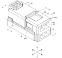
- FIG. 1 is a perspective view showing a connector according to an embodiment.
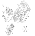
- FIG. 2 is an exploded perspective view showing the connector.
- FIG. 3 is an exploded perspective view showing the connector.
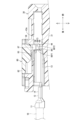
- FIG. 4 is a partial sectional view taken along the line IV--IV in FIG.
- FIG. 5 is a partial sectional view taken along the line VV in FIG.
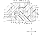
- FIG. 6 is a partial cross-sectional view taken along the line IV--IV in FIG. 1, showing a temporarily attached state of the retainer.
- FIG. 7 is a partial cross-sectional view taken along the line VV in FIG. 1, showing a state in which the retainer is temporarily attached.
- the connector of the present disclosure is as follows.
- a connector for holding a terminal comprising a housing in which a cavity capable of accommodating the terminal is formed, and a retainer that can be attached to the housing at a temporary attachment position and a main attachment position, and the retainer includes:
- the retainer is a connector including a lance that can be temporarily locked to the terminal in the cavity at the temporary mounting position, and a locking convex portion that can be locked to the terminal in the cavity at the main mounting position.
- the retainer is provided with a lance that temporarily locks the terminal. Therefore, the shape of the housing can be simplified, and the connector can be made smaller.
- the lance can be temporarily locked in the recess that is locked by the locking protrusion. Therefore, it is not necessary to separately form a portion on the terminal where the lance temporarily locks. This makes it possible to simplify and miniaturize the terminal, which also contributes to miniaturization of the connector.
- the lance is formed so as to protrude in the same direction as the locking wall at the middle of the retainer body in the extending direction so that it can be placed in the temporary mounting opening, and is designed to be transverse to the extending direction of the cavity. elastically deforms along the direction of Therefore, the configuration for forming the lance can be made smaller compared to the case where the lance is positioned along the extending direction of the cavity. This makes it possible to reduce the size of the connector in the front-rear direction.
- the base end of the lance may be integrally connected to the locking protrusion. This makes it easy to reinforce the lance even if the protruding length of the lance is increased.
- the lance includes an elastic piece and a temporary locking convex portion that protrudes toward the cavity at a location away from the base end of the elastic piece.
- the lance In a state where the retainer is located at the temporary attachment position, the lance is placed in the temporary attachment opening, and the temporary locking protrusion protrudes into the cavity to temporarily lock the terminal in the cavity.
- the temporary locking convex portion With the retainer in the permanently attached position, the temporary locking convex portion moves beyond the terminal to release the temporary lock on the terminal, and The convex portion may protrude into the cavity and become capable of being locked to the terminal within the cavity.
- the retainer when the retainer is located at the temporary attachment position, it can be temporarily locked to the terminal by the lance.
- the retainer is pushed and moved to the final mounting position, the temporary locking between the lance and the terminal is released, and the locking protrusion can lock onto the terminal without the lance getting in the way.
- the temporary locking convex portion has a protruding dimension that gradually decreases as it goes toward the side where the terminal is inserted in the extending direction of the cavity. and a second guide surface that gradually reduces the protrusion dimension of the temporary locking convex portion toward the distal end side of the lance.
- the temporary locking protrusion protrudes into the cavity.
- the terminal contacts the first guide surface and elastically deforms the lance in a direction to retreat from the cavity.
- the lance elastically returns to its original shape, allowing the temporary locking convex portion to temporarily lock the terminal.
- the retainer is pushed from the temporary mounting position to the final mounting position, the second guide surface comes into contact with the terminal, and the lance is elastically deformed in a direction to retreat from the cavity. Therefore, the temporary locking convex portion crosses over the terminal, and the temporary locking between the lance and the terminal is released.
- the retainer is guided by the configuration in which the lance is arranged in the slit-shaped opening for temporary attachment. Further, the lance can be elastically deformed by utilizing the space within the slit.
- the vertical wall may include an outer wall exposed on either side of the housing, and the temporary attachment opening may be a slit formed in the outer wall.
- the opening for temporary attachment is a slit formed in the outer wall, it is easy to secure a space for elastically deforming the lance outward.
- the locking part for permanent mounting is formed in an elongated convex shape along the extending direction of the cavity, and the opening for temporary mounting includes at least one of the pair of locking parts for temporary mounting and the pair of locking parts for permanent mounting. It may be a slit formed across at least one of the locking parts.
- the locking wall portion locks into the temporary attachment locking portion or the permanent attachment locking portion near where the lance is guided by the slit-shaped temporary attachment opening. This allows the locking wall portion to smoothly lock into the temporary attachment locking portion or the permanent attachment locking portion.
- FIG. 1 is a perspective view showing the connector 20.
- 2 and 3 are exploded perspective views showing the connector 20.
- FIG. 4 is a partial sectional view taken along the line IV--IV in FIG.
- FIG. 5 is a partial sectional view taken along the line VV in FIG. In FIG. 5, the electric wire 18 is shown by a two-dot chain line.
- 6 is a diagram illustrating a temporarily attached state of the retainer in a partial cross section taken along the line IV--IV in FIG. 1
- FIG. 7 is a diagram showing a temporarily attached state of the retainer in a partial cross-section taken along the line V-V in FIG.
- Connector 20 holds terminal 10.
- the terminal 10 is formed by pressing a metal plate.
- the terminal 10 includes a covering crimping section 11 , a core crimping section 12 , and a terminal connecting section 13 .
- the covering crimping portion 11 is a portion that is crimped to the covering portion of the end of the electric wire 18 .
- the core wire crimping portion 12 is a portion that is crimped onto the core wire portion exposed at the end of the electric wire 18.
- the terminal connecting portion 13 is a portion connected to a mating terminal, and is formed, for example, in a cylindrical shape.
- the covering crimping part 11, the core wire crimping part 12, and the terminal connecting part 13 are linearly arranged in this order.
- the thickness of the covering crimping part 11 and the terminal connecting part 13 is larger than the thickness of the core wire crimping part 12. Therefore, when the terminal 10 is observed from the side, a recess 14 is formed on the core wire crimping part 12 and between the covering crimping part 11 and the terminal connecting part 13, which is recessed in a part of the extending direction of the terminal 10. Ru.
- the connector 20 holds multiple terminals 10. More specifically, multiple (e.g., two) terminals 10 are held in multiple stages (e.g., two stages). In each stage, multiple terminals 10 are lined up in a row in parallel. Note that the multiple terminals 10 may be terminals of the same size and material, or terminals of different sizes or materials. Note that the number of terminals 10 held by the connector 20 is arbitrary.
- the connector 20 includes a housing 30 and a retainer 80.
- the retainer 80 holds the plurality of terminals 10 in at least one stage from the housing 30.
- the connector 20 further includes a cover 60.
- the cover 60 is attached to the housing 30 on the opposite side of the retainer 80.
- the cover 60 holds the plurality of terminals 10 in other stages so that they do not come off the housing 30.
- the terminal connecting portion 13 side may be referred to as the front side
- the covering crimping portion 11 side may be referred to as the rear side in the extending direction of the terminal 10.
- the cover 60 side may be referred to as the lower side
- the retainer 80 side may be referred to as the upper side.
- the left and right direction may be referred to while assuming a state where the user stands on the cover 60 and faces the front side.
- the housing 30 is made of resin or the like, and includes terminal accommodating portions 32 and 42.
- the housing 30 includes a lower terminal accommodating part 32 and an upper terminal accommodating part 42.
- the lower terminal accommodating portion 32 has a cavity 34 in which the terminal 10 is accommodated.
- the lower terminal accommodating portion 32 has a plurality of (here, two) cavities 34 arranged in parallel.
- the upper terminal accommodating portion 42 has a cavity 44 in which the terminal 10 is accommodated.
- the upper terminal accommodating portion 42 has a plurality of (here, two) cavities 44 arranged in parallel.
- the retainer 80 is combined with the upper terminal accommodating portion 42 to hold the terminal 10 within the upper cavity 44. That is, the terminal 10 is inserted into the cavity 44 before the retainer 80 is fully attached. With the terminal 10 inserted into the cavity 44, the retainer 80 is permanently attached to the upper terminal accommodating portion 42. This prevents the terminal 10 from coming out of the upper cavity 44.
- the cover 60 is combined with the lower terminal accommodating portion 32 to hold the terminal 10 within the lower cavity 34. That is, the terminal 10 is set in the lower cavity 34 before the cover 60 is attached to the lower terminal accommodating portion 32. In this state, the cover 60 is attached to the lower terminal accommodating portion 32. This prevents the terminal 10 from coming out from the lower cavity 34.
- this connector it is not essential for this connector to include the cover 60 and the terminals 10 held by the cover 60.
- the retainer 80 is configured to be attachable to the housing 30 at a temporary attachment position and a permanent attachment position.
- the actual attachment is a state in which the retainer 80 is locked to the terminal 10 so as to prevent the terminal 10 from coming off when the connector 20 is in use.
- the retainer 80 is attached to the housing 30 in the main attachment position, the terminals 10 will not come off from the housing 30 and will be retained in the cavity 44 even if the connector 20 is carried or inserted or removed from a mating connector.
- Temporary attachment is a state in which the terminal 10 can be temporarily locked in a state before the actual attachment state.
- the force with which the retainer 80 holds the terminals 10 in the temporarily attached state is smaller than the force with which the retainer 80 holds the terminals 10 in the permanently attached state.
- the holding force of the terminals 10 by the retainer 80 in the temporarily attached state may be large enough to hold the terminals 10 during the operation of moving the retainer 80 from the temporary attaching position to the actual attaching position.
- the housing 30 has a partition plate portion 31 that separates the upper stage cavity 44 from the lower side.
- the partition plate portion 31 is located between the lower terminal accommodating portion and the lower terminal accommodating portion, and separates the lower cavity 34 from the upper cavity 44.
- the partition plate portion 31 can also be understood as a bottom plate located at the bottom of the upper stage cavity 44.
- the housing 30 has vertical walls 43a, 43b from the partition plate portion 31 toward the upper side.
- the vertical walls 43a, 43b are plate-shaped portions that are perpendicular to the partition plate portion 31 and extend along the extension direction of the cavity 44.
- the vertical walls 43a, 43b are also aligned with the protruding direction of the locking wall portion 84 described later.
- the vertical walls 43a, 43b include a pair of outer walls 43a located on both sides of the housing 30.
- the pair of outer walls 43a are exposed to the left or right outside of the housing 30.
- the vertical walls 43a, 43b also include an intermediate wall 43b that separates the multiple cavities 44.
- the intermediate wall 43b is located between a pair of outer walls 43a, and the pair of outer walls 43a and the intermediate wall 43b are arranged in parallel with a gap in the width direction of the housing 30.
- a front plate portion 31F is provided at the front edge of the housing 30 and extends in a direction perpendicular to the front-rear direction.
- the front plate portion 31F is located at the front end of the cavity 44.
- the terminal 10 disposed within the cavity 44 is restricted from moving forward by coming into contact with the front plate portion 31F.
- a connection hole 31Fa is formed in the front plate portion 31F, into which a mating terminal (for example, a male terminal having an elongated plate portion or a pin-shaped portion) can be inserted.
- the counterpart terminal can be connected to the terminal 10 in the cavity 44 through the connection hole 31Fa.
- the upper terminal accommodating portion 42 is configured to include an upper portion of the partition plate portion 31, a pair of outer walls 43a, an intermediate wall 43b, a ceiling plate portion 43c, and a front plate portion 31F.
- a plurality of cavities 44 are formed in each gap between the two.
- the cavity 44 has a rear opening, and the terminal 10 is inserted into the cavity through the rear opening.
- the housing 30 has an opening 36 for permanent mounting and an opening 38 for temporary mounting.
- the middle part of the ceiling plate part 43c of the housing 30 in the extending direction of the cavity 44 is formed to be partially recessed, and the main mounting opening 36 is formed in a part of the recessed part.
- the front end of the terminal 10 disposed within the cavity 44 in contact with the front plate portion 31F, at least a portion of the recess 14 of the terminal 10 can be exposed to the outside of the housing 30 through the main mounting opening 36. .
- the pair of outer walls 43a of the housing 30 are partially recessed at the rear, and a temporary mounting opening 38 is formed in a part of the recessed portion.
- the temporary mounting opening 38 is formed as a slit extending in a direction perpendicular to the extension direction of the cavity 44.
- the temporary mounting opening 38 is also a slit along the protruding direction of the locking wall portion 84 described later.
- the temporary mounting opening 38 is located in front of the actual mounting opening 36 in the extension direction of the cavity 44.
- the temporary mounting opening 38 extends downward beyond the bottom surface of the cavity 44 on the side opposite to the main mounting opening 36.
- a recess 44h is partially formed in the bottom portion of the cavity 44 at a position corresponding to the tip of the temporary attachment opening 38.
- the recess is continuous with the temporary mounting opening 38, and in the main mounting state, the temporary locking convex portion 88 of the lance 86 is arranged in the recess 44h (see FIGS. 4 and 6).
- the retainer 80 can be attached to the housing 30 at a temporary attachment position and an actual attachment position.
- the retainer 80 includes a lance 86 and a locking protrusion 83.
- the lance 86 is temporarily locked to the terminal 10 in the cavity 44, allowing the temporary attachment state to be established.
- the lance 86 protrudes into the cavity 44 through the temporary attachment opening 38 and temporarily locks onto the terminal 10 .
- the locking protrusion 83 locks on the terminal 10 in the cavity 44, and the main mounting state can be established.
- the locking convex portion 83 can protrude into the cavity 44 through the main mounting opening 36 and lock onto the terminal 10 .
- the housing 30 has a pair of temporary attachment locking parts 47 and a pair of permanent installation locking parts 46.
- the pair of temporary attachment locking portions 47 are portions that lock onto the pair of locking wall portions 84 of the retainer 80 when the retainer 80 is located at the temporary attachment position.
- the pair of full-attachment locking portions 46 are portions that lock onto the pair of locking wall portions 84 of the retainer 80 when the retainer 80 is in the full-attachment position.
- the pair of temporary attachment locking portions 47 protrude outward from the bottom surface of the recessed portion of the outer surface of the pair of outer walls 43a.
- the pair of temporary attachment locking portions 47 are formed in a shape that includes a tip of the outer wall 43a, that is, a portion whose protruding size gradually decreases upward.
- the pair of main attachment locking parts 46 protrude outward from the bottom surface of the recessed portion of the outer surface of the pair of outer walls 43a.
- the pair of main attachment locking portions 46 are formed in a shape that includes a tip of the outer wall 43a, that is, a portion whose protruding size gradually decreases upward.
- the pair of temporary attachment locking portions 47 are located on the side closer to the actual attachment opening 36, that is, on the upper side, with respect to the pair of permanent attachment locking portions 46. Therefore, after the retainer 80 is temporarily locked in the pair of locking parts 47 for temporary installation and is in the temporarily installed state, the retainer 80 is further pushed and locked in the pair of locking parts 46 for permanent installation, so that the retainer 80 can be permanently installed. can become a state.
- the pair of locking parts 46 for permanent mounting and the pair of locking parts 47 for temporary mounting are formed in an elongated convex shape along the direction in which the cavity 44 extends.
- the front ends of the pair of locking parts 46 for permanent mounting and the pair of locking parts 47 for temporary mounting are located on the front side of the opening 36 for permanent mounting.
- the rear end of the stop portion 47 is located on the rear side of the main mounting opening 36 .
- the temporary attachment opening 38 extends across the permanent attachment locking portion 46 and the temporary attachment locking portion 47 in each of the pair of outer walls 43a. Therefore, when the housing 30 is observed from the side, the slit-shaped temporary attachment opening 38 intersects the intermediate portion in the extending direction of the permanent attachment locking part 46 and the temporary attachment locking part 47.
- the opening 38 for temporary attachment may cross the locking part 46 for permanent attachment or the locking part 47 for temporary attachment.
- the opening 38 for temporary attachment does not need to cross the locking part 46 for permanent attachment and the locking part 47 for temporary attachment.
- the retainer 80 includes a retainer body 82 and a pair of locking walls 84.
- the retainer main body 82 is a part that is attached to the main attachment opening 36.
- the retainer main body 82 is formed into a plate shape that expands to a size that can block the main mounting openings 36 corresponding to the plurality of cavities 44 all at once.
- the middle portion of the ceiling plate portion 43c in the front-rear direction is partially recessed, and the retainer body 82 is formed into a plate shape that can be placed in the recessed portion of the ceiling plate portion 43c.
- the retainer body 82 With the retainer body 82 disposed in the recessed portion, the front end of the retainer body 82 contacts the end surface of the ceiling plate portion 43c located on the front side of the recessed portion, and the rear end of the retainer body 82 contacts the end surface of the ceiling plate portion 43c. comes into contact with the end surface located on the rear side of the concave portion. Thereby, the retainer 80 is positioned in the front-rear direction.
- a locking protrusion 83 is formed on the retainer body 82.
- a plurality of locking protrusions 83 are formed in parallel in correspondence with a plurality of cavities 44.
- the locking convex portion 83 is formed at an intermediate portion in the extending direction of the cavity 44 , more specifically, in a region where the core wire crimping portion 12 is located in the extending direction of the cavity 44 .
- the locking convex portion 83 has an elongated shape along the direction in which the cavity 44 extends.
- the length of the locking convex portion 83 is set, for example, to a length that is equal to or less than the distance between the covering crimping portion 11 and the terminal connecting portion 13 to the extent that the terminal 10 can be positioned in the extending direction.
- the locking protrusion 83 When the retainer body 82 is attached to the full-attachment opening 36, the locking protrusion 83 is positioned at a position corresponding to the full-attachment opening 36.
- the locking protrusion 83 When the retainer 80 is in a temporary attachment state, the locking protrusion 83 does not protrude into the cavity 44, but is positioned within the full-attachment opening 36 or further outward.
- the locking protrusion 83 can protrude from the retainer body 82 into the cavity 44. In this state, the locking protrusion 83 can fit into the recess 14 between the insulation crimping portion 11 and the terminal connection portion 13 of the terminal 10 in the cavity 44. This positions the terminal 10 in its extension direction, preventing it from slipping out backwards.
- the pair of locking walls 84 extend from both sides of the retainer body 82 to both sides of the terminal accommodating part 42, here along the outer surfaces of the pair of outer walls 43a.
- a retaining protrusion 85 is formed at a position closer to the tip of the inner surface of the pair of locking walls 84 .
- the retaining convex portion 85 is a convex portion that protrudes from the inner surface of the locking wall portion 84.
- the retaining convex portion 85 has a shape that includes a portion whose protruding size gradually decreases toward the tip side of the retaining wall portion 84. is formed.
- the pair of locking wall parts 84 can be locked to the pair of locking parts 47 for temporary mounting or the pair of locking parts 46 for permanent mounting.
- the retaining convex portion 85 may have an elongated convex shape along the extending direction of the cavity 44.
- the retaining convex portion 85 may have a length that is approximately the same as the length of the pair of temporary attachment locking portions 47 or the pair of permanent attachment locking portions 46 .
- the entire extending direction of the retaining convex portion 85 can be locked to the pair of temporary attachment locking portions 47 or the pair of permanent installation locking portions 46, and the retainer 80 is in the temporarily installed state or the fully installed state. becomes stable.
- the lance 86 is a portion that temporarily locks the retainer 80 to the terminal 10 in the cavity 44 when it is located at the temporary mounting position.
- the lance 86 is formed to protrude in the same direction as the locking wall portion 84 at an intermediate position in the extending direction of the retainer body 82 so that it can be placed in the temporary attachment opening 38. More specifically, the lance 86 is a portion of the retainer body 82 that faces the terminal accommodating portion 42 and protrudes from a portion between the pair of locking walls 84 . With the retainer 80 attached to the opening 36 for permanent attachment, the lance 86 is placed in the opening 38 for temporary attachment.
- the lance 86 is elongated in a direction orthogonal to the extending direction of the cavity 44 and is configured to be elastically deformable along a direction crossing the extending direction of the cavity 44 .
- the longitudinal length of the lance 86 may be the same as the width of the gap in the longitudinal direction of the temporary attachment opening 38 to such an extent that the lance 86 fits in the temporary attachment opening 38 without wobbling in the longitudinal direction.
- the base end of the lance 86 is integrally connected to one side of the locking convex portion 83. Therefore, compared to the case where the lance 86 protrudes from the retainer main body 82 without being connected to the locking convex portion 83, a reinforced configuration is obtained. This makes the lance 86 difficult to break. Due to the configuration in which the lance 86 is guided by the temporary attachment opening 38 in the extending direction of the cavity 44, the locking convex portion 83 is guided toward the permanent attachment opening 36, and the retainer 80 is smoothly attached.
- the lance 86 has an elastic piece 87 and a temporary locking convex portion 88.
- the elastic piece 87 is an elongated portion that extends in a direction (vertical direction here) that intersects (perpendicularly here) to the extending direction of the cavity 44 and extends in a direction that intersects (here perpendicularly) to the extending direction of the cavity 44. It is configured to be elastically deformable in the direction of movement (in this case, the left-right direction).
- the base end of the elastic piece 87 is integrally connected to the outer surface of the locking convex portion 83.
- the tip of the elastic piece 87 further protrudes from the tip of the locking projection 83 and can be easily elastically deformed in the left-right direction.
- the temporary locking convex portion 88 is formed to protrude toward the cavity 44 at a position away from the base end of the elastic piece 87.
- the temporary locking protrusion 88 projects toward the cavity 44 at a position away from the tip of the locking protrusion 83 .
- the temporary locking convex portion 88 With the lance 86 disposed in the temporary attachment opening 38, the temporary locking convex portion 88 can protrude into the cavity 44 from the temporary attachment opening 38. Therefore, the temporary locking convex portion 88 can be temporarily locked in the recess 14 of the terminal 10 from the right side or the left side of the terminal 10.
- the temporary locking convex portion 88 is arranged at a position away from the tip of the locking convex portion 83, the temporary locking convex portion 88 can be temporarily locked in the recess 14.
- the temporary locking projection 88 can be positioned beyond the recess 14 while the locking projection 83 is locked in the recess.
- the provisional locking protrusion 88 has a first guide surface 88f1 and a second guide surface 88f2.
- the first guide surface 88f1 is a surface of the temporary locking convex portion 88 that faces diagonally backward.
- the first guide surface 88f1 is a surface that gradually reduces the protrusion dimension of the temporary locking convex portion 88 toward the side (rear side) into which the terminal 10 is inserted in the extending direction of the cavity 44.
- the second guide surface 88f2 is a surface of the temporary locking convex portion 88 that faces diagonally downward.
- the second guide surface 88f2 is a surface that gradually reduces the protrusion dimension of the temporary locking convex portion 88 toward the distal end side of the lance 86.
- the temporary locking convex portion 88 protrudes from the temporary attachment opening 38 into the cavity 44 and is disposed in the recess 14 of the terminal 10.
- the forward facing surface of the temporary locking convex portion 88 may be a temporary locking surface 88f3 perpendicular to the extending direction of the cavity 44.
- the temporary locking surface 88f3 is a surface that comes into contact with the terminal connecting portion 13 and attempts to remove the terminal 10 when the terminal 10 attempts to come out of the cavity 44 rearward. If the temporary locking surface 88f3 is perpendicular to the extending direction of the cavity 44, even if the temporary locking surface 88f3 contacts the terminal connecting portion 13, the lance 86 will elastically deform in the direction to release the temporary locking. hard. Therefore, the temporarily locked state is effectively maintained.
- a retainer 80 is prepared in which a pair of retaining convex portions 85 are locked to a pair of temporary attachment locking portions 47 (see FIGS. 6 and 7).
- the locking convex portion 83 does not protrude into the cavity 44. Therefore, when the terminal 10 is inserted into the cavity 44 through the rear opening 45, it can be inserted into the back of the cavity 44, that is, to the front side, without being caught by the locking protrusion 83.
- the elastic piece 87 of the lance 86 is disposed within the temporary attachment opening 38.
- the temporary locking protrusion 88 protruding from the elastic piece 87 protrudes from the temporary attachment opening 38 into the cavity 44. Therefore, when the terminal 10 is inserted into the cavity 44 through the rear opening 45, the terminal connection portion 13 of the terminal 10 comes into contact with the temporary locking protrusion 88.
- the tip of the terminal connection portion 13 comes into contact with the first guide surface 88f1 of the temporary locking convex portion 88 (see FIG. 7).
- the first guide surface 88f1 is a surface that gradually reduces the protruding dimension of the temporary locking convex portion 88 as the terminal 10 is inserted toward the rear side. Therefore, when the terminal 10 is inserted deep into the cavity 44, the tip of the terminal connecting portion 13 comes into contact with the first guide surface 88f1, and the temporary locking convex portion 88 is moved in the direction of retreating from the cavity 44, that is, on the right side. Or push it out to the left. Thereby, the terminal 10 can be moved to the back of the cavity 44, that is, to the front side.
- the temporary locking convex portion 88 When the terminal connecting portion 13 passes over the temporary locking convex portion 88, the temporary locking convex portion 88 returns to the state of protruding into the cavity 44 due to the elastic force of the elastic piece 87 to return to its original shape. As a result, the temporary locking convex portion 88 becomes temporarily locked in the recess 14 of the terminal 10 (see FIG. 6).
- the terminal 10 is inserted into each cavity 44 in the same manner as above. With each terminal 10 inserted into each cavity 44, the temporary locking convex portion 88 temporarily locks the terminal 10. Therefore, once the terminal 10 is inserted into the cavity 44, the insertion work of the terminal 10 can be easily carried out one after another without worrying about the terminal 10 coming off later.
- the retainer 80 is pushed from the temporary mounting position to the final mounting position.
- the temporary locking convex portion 88 is pushed downward in the direction in which the retainer 80 is pushed, that is, perpendicular to the direction in which the cavity 44 extends. Then, the temporary locking convex portion 88 moves from the recess 14 toward the core wire crimping portion 12 and comes into contact with the core wire crimping portion 12 .
- the second guide surface 88f2 is a surface that gradually reduces the protrusion dimension of the temporary locking convex portion 88 toward the distal end side of the lance 86.
- the second guide surface 88f2 comes into contact with the core wire crimping part 12, and the temporary locking convex part 88 moves in the direction of retreating from the cavity 44, that is, to the outer right side or the outer left side.
- the temporary locking convex portion 88 moves beyond the core wire crimping portion 12 and below the core wire crimping portion 12, and the temporary locking with respect to the terminal 10 is released.
- the temporary locking convex portion 88 that has exceeded the core wire crimping portion 12 downward returns to its original position on the side of the cavity 44 by the elastic force of the elastic piece 87, and is disposed in the partial recess 44h of the cavity 44.
- the locking protrusion 83 enters into the cavity 44 through the main mounting opening 36.
- the locking convex portion 83 enters into the recess 14 from the side opposite to the core wire crimping portion 12.
- the retainer 80 includes the lances 86 that can be temporarily engaged with the terminals 10 in the temporary attachment position, and the locking protrusions that can be engaged with the terminals 10 in the final attachment position. This makes it possible to simplify the shape of the housing 30, and to reduce the size of the connector 20.
- the shape of the housing tends to be more complicated. Furthermore, since the housing often includes a guide structure, a lock structure, etc. for connection to a mating connector, the shape of the housing tends to become complicated from this point of view as well. For this reason, forming a lance in the housing tends to increase the size due to mold restrictions.
- the lance 86 on the retainer 80 as in this embodiment, it becomes possible to simplify the shape of the housing 30 and make it smaller. Further, since the retainer 80 has a simpler shape than the housing 30, even if the housing 30 is formed on the retainer 80, there are few mold restrictions, and the retainer 80 is less likely to become large. Therefore, the shape of the connector 20 as a whole can be simplified and the size can be reduced.
- both the lance 86 and the locking protrusion 83 can be locked in the recess 14 of the terminal 10. Therefore, there is no need to separately form a portion on the terminal 10 where the lance 86 temporarily locks. This makes it possible to simplify and downsize the terminal 10, which contributes to downsizing the connector 20.
- the lance and the locking protrusion may lock at different locations with respect to the terminal.
- the lance 86 is formed to protrude in the same direction as the locking wall portion 84 in the middle of the retainer body 82 in the extending direction so that it can be placed in the temporary attachment opening 38 . elastically deforms along the direction that intersects with the For this reason, the configuration for forming the lance 86 can be made smaller compared to the case where the lance is placed along the extending direction of the cavity. This makes it possible to reduce the size of the connector 20 in the front-rear direction.
- the lance may be along the extending direction of the cavity.
- the lance may protrude from the locking wall along the extending direction of the cavity, and an opening may be formed in the side of the housing in which the lance can be placed.
- the base end of the lance 86 is integrally connected to the locking convex portion 83. Therefore, the lance 86 is reinforced and is less likely to be damaged.
- the lance 86 has an elastic piece 87 and a temporary locking convex portion 88, and when the retainer 80 is located at the temporary installation position, the lance 86 is placed in the temporary installation opening 38 and is temporarily locked.
- the locking convex portion 88 protrudes into the cavity 44 and locks in the recessed portion of the terminal 10 in a detachable manner.
- the temporary locking convex portion 88 moves beyond the terminal 10 to release the temporary lock on the terminal 10.
- the retainer main body 82 is attached to the main attachment opening 36, and the locking protrusion 83 protrudes into the cavity 44 and locks into the recess of the terminal 10.
- the lance 86 can be temporarily locked to the terminal 10 with the retainer 80 located at the temporary attachment position.
- the retainer 80 is pushed and moved to the final mounting position, the temporary locking between the lance 86 and the terminal 10 is released, and the locking convex portion 83 temporarily locks the terminal 10.
- the lance 86 and the locking protrusion 83 are at the same position or at least partially overlap in the extending direction of the terminal 10, the lance 86 and the locking protrusion 83 are in the same position in the recess 14 of the terminal 10. It is easy to realize a locking configuration.
- the temporary locking convex portion 88 has a first guide surface 88f1 and a second guide surface 88f2. Therefore, when the terminal 10 is inserted into the cavity 44 with the retainer 80 located at the temporary attachment position, the terminal 10 can come into contact with the first guide surface 88f1. Thereby, the lance 86 is easily elastically deformed in the direction of retreating from the cavity 44. When the terminal 10 is further pushed in, the lance 86 elastically returns to its original shape, and the temporary locking protrusion 88 can temporarily lock the terminal 10.
- the retainer 80 when the retainer 80 is pushed from the temporary mounting position to the main mounting position, the second guide surface 88f2 comes into contact with the terminal 10, and the lance 86 can easily be elastically deformed in the direction of retreating from the cavity 44. Therefore, the temporary locking convex portion 88 passes over the terminal 10, and the temporary locking between the lance 86 and the terminal 10 is released. This makes it easy to temporarily lock the lance 86 to the terminal 10 by inserting the terminal 10, and to release the temporary lock between the lance 86 and the terminal 10 by pushing the lance 86.
- the locking protrusion 83 can be easily locked in the recess 14.
- the lance may maintain a state in which it is temporarily locked in the terminal 10.
- the housing 30 includes an outer wall 43a as a vertical wall, and the temporary mounting opening 38 is formed in the outer wall 43a as a slit along the protruding direction of the locking wall portion 84. Therefore, the retainer 80 is guided by the configuration in which the lance 86 is arranged in the slit-shaped temporary attachment opening 38. Furthermore, the lance 86 is easily elastically deformed by utilizing the space within the slit.
- the temporary attachment opening 38 is formed in the outer wall 43a, it is easy to secure a space in which the lance 86 can be elastically deformed outside the outer wall 43a. Thereby, even if the temporary locking convex portion 88 is sufficiently protruded into the cavity 44, the lance 86 can be largely elastically deformed outward. By sufficiently protruding the temporary locking convex portion 88 into the cavity 44, it is easy to maintain the state in which the lance 86 is temporarily locked to the terminal 10.
- a slit-shaped opening 38 for temporary attachment crosses the locking part 47 for temporary attachment and the locking part 46 for permanent attachment. Therefore, near the position where the lance 86 is guided by the opening 38 for temporary attachment, the retaining convex portion 85 of the locking wall portion 84 locks with the locking portion 47 for temporary attachment or the locking portion 46 for permanent attachment. Therefore, the retaining convex portion 85 of the retaining wall portion 84 can be smoothly engaged with the temporary attaching retaining portion 47 or the permanent attaching retaining portion 46.
- the locking area between the retaining protrusion 85 and the main mounting locking part 46 is intermediate.
- the locking protrusion 83 locks onto the terminal 10. Therefore, the terminal 10 is more firmly prevented from coming off by the locking convex portion 83.
- the connector may have three or more cavities lined up.
- an opening for temporary attachment may be formed in the wall that partitions the cavity, and the lance may be placed within the opening for temporary attachment.
- the above configuration is also applicable to a configuration in which terminals inserted into cavities in multiple stages are prevented from coming off by the same retainer.
- the retainer main body 82, the locking protrusion 83, and the lance 86 may be provided in multiple stages corresponding to each stage.
- Terminal 11 Covering crimping part 12 Core wire crimping part 13 Terminal connection part 14 Recess 18 Wire 20 Connector 30 Housing 31 Partition plate part 31F Front plate part 31Fa Connection hole 32, 42 Terminal housing part 34, 44 Cavity 36 Opening for actual mounting 38 Temporary disguise Wearing opening 43a Outer wall (vertical wall) 43b Intermediate wall (vertical wall) 43c Ceiling plate portion 44h Recess 45 Rear opening 46 Locking portion for permanent attachment 47 Locking portion for temporary attachment 60 Cover 80 Retainer 82 Retainer body 83 Locking protrusion 84 Locking wall portion 85 Retaining protrusion 86 Lance 87 Elastic piece 88 Temporary locking convex portion 88f1 First guide surface 88f2 Second guide surface 88f3 Temporary locking surface
Landscapes
- Connector Housings Or Holding Contact Members (AREA)
Priority Applications (1)
| Application Number | Priority Date | Filing Date | Title |
|---|---|---|---|
| CN202380063472.9A CN119817008A (zh) | 2022-09-21 | 2023-08-31 | 连接器 |
Applications Claiming Priority (2)
| Application Number | Priority Date | Filing Date | Title |
|---|---|---|---|
| JP2022149879A JP2024044389A (ja) | 2022-09-21 | 2022-09-21 | コネクタ |
| JP2022-149879 | 2022-09-21 |
Publications (1)
| Publication Number | Publication Date |
|---|---|
| WO2024062886A1 true WO2024062886A1 (ja) | 2024-03-28 |
Family
ID=90454164
Family Applications (1)
| Application Number | Title | Priority Date | Filing Date |
|---|---|---|---|
| PCT/JP2023/031703 Ceased WO2024062886A1 (ja) | 2022-09-21 | 2023-08-31 | コネクタ |
Country Status (3)
| Country | Link |
|---|---|
| JP (1) | JP2024044389A (https=) |
| CN (1) | CN119817008A (https=) |
| WO (1) | WO2024062886A1 (https=) |
Citations (3)
| Publication number | Priority date | Publication date | Assignee | Title |
|---|---|---|---|---|
| JP2002373725A (ja) * | 2001-06-15 | 2002-12-26 | Sumitomo Wiring Syst Ltd | コネクタ |
| JP2003031291A (ja) * | 2001-07-12 | 2003-01-31 | Sumitomo Wiring Syst Ltd | コネクタ |
| JP2007012352A (ja) * | 2005-06-29 | 2007-01-18 | Sumitomo Wiring Syst Ltd | コネクタ |
Family Cites Families (1)
| Publication number | Priority date | Publication date | Assignee | Title |
|---|---|---|---|---|
| JP4958684B2 (ja) * | 2007-08-21 | 2012-06-20 | 矢崎総業株式会社 | コネクタ |
-
2022
- 2022-09-21 JP JP2022149879A patent/JP2024044389A/ja active Pending
-
2023
- 2023-08-31 WO PCT/JP2023/031703 patent/WO2024062886A1/ja not_active Ceased
- 2023-08-31 CN CN202380063472.9A patent/CN119817008A/zh active Pending
Patent Citations (3)
| Publication number | Priority date | Publication date | Assignee | Title |
|---|---|---|---|---|
| JP2002373725A (ja) * | 2001-06-15 | 2002-12-26 | Sumitomo Wiring Syst Ltd | コネクタ |
| JP2003031291A (ja) * | 2001-07-12 | 2003-01-31 | Sumitomo Wiring Syst Ltd | コネクタ |
| JP2007012352A (ja) * | 2005-06-29 | 2007-01-18 | Sumitomo Wiring Syst Ltd | コネクタ |
Also Published As
| Publication number | Publication date |
|---|---|
| JP2024044389A (ja) | 2024-04-02 |
| CN119817008A (zh) | 2025-04-11 |
Similar Documents
| Publication | Publication Date | Title |
|---|---|---|
| JP3003679B1 (ja) | コネクタ | |
| JP2013247053A (ja) | コネクタ | |
| JP4980342B2 (ja) | ターミナル位置保証機構を備えた電気コネクタ | |
| JP3969161B2 (ja) | コネクタ | |
| JP2003168512A (ja) | コネクタ | |
| JP2004355969A (ja) | コネクタ | |
| JP4457987B2 (ja) | コネクタ | |
| WO2024062886A1 (ja) | コネクタ | |
| JP2022107105A (ja) | コネクタおよびコネクタ装置 | |
| JPH1116625A (ja) | コネクタの二重係止部材 | |
| JP3889682B2 (ja) | コネクタ | |
| JP4372933B2 (ja) | 電気コネクタの端子係止構造 | |
| JP2020161323A (ja) | コネクタハウジング | |
| JP3286195B2 (ja) | ハウジングへのフロントホルダの係止構造 | |
| JP7389407B2 (ja) | カードエッジコネクタ | |
| JP2553821Y2 (ja) | コネクタ | |
| JP2005166611A (ja) | コネクタ | |
| JP4341465B2 (ja) | コネクタ | |
| JP7243551B2 (ja) | コネクタ | |
| WO2024166628A1 (ja) | コネクタ | |
| KR20240076679A (ko) | 커넥터 | |
| JP7230753B2 (ja) | コネクタ | |
| JP6965990B2 (ja) | コネクタ | |
| JPH11167949A (ja) | コネクタ | |
| JPH11176506A (ja) | コネクタハウジングと端子金具との係止構造、それに使用する端子金具、及び、コネクタハウジング |
Legal Events
| Date | Code | Title | Description |
|---|---|---|---|
| 121 | Ep: the epo has been informed by wipo that ep was designated in this application |
Ref document number: 23868010 Country of ref document: EP Kind code of ref document: A1 |
|
| WWE | Wipo information: entry into national phase |
Ref document number: 202380063472.9 Country of ref document: CN |
|
| WWP | Wipo information: published in national office |
Ref document number: 202380063472.9 Country of ref document: CN |
|
| NENP | Non-entry into the national phase |
Ref country code: DE |
|
| 122 | Ep: pct application non-entry in european phase |
Ref document number: 23868010 Country of ref document: EP Kind code of ref document: A1 |