WO2024062584A1 - 車両の下部構造 - Google Patents
車両の下部構造 Download PDFInfo
- Publication number
- WO2024062584A1 WO2024062584A1 PCT/JP2022/035283 JP2022035283W WO2024062584A1 WO 2024062584 A1 WO2024062584 A1 WO 2024062584A1 JP 2022035283 W JP2022035283 W JP 2022035283W WO 2024062584 A1 WO2024062584 A1 WO 2024062584A1
- Authority
- WO
- WIPO (PCT)
- Prior art keywords
- vehicle
- cross member
- width direction
- drive shaft
- suspension cross
- Prior art date
Links
- 230000003014 reinforcing effect Effects 0.000 claims description 9
- 239000000725 suspension Substances 0.000 abstract description 70
- 230000005540 biological transmission Effects 0.000 description 6
- 238000010586 diagram Methods 0.000 description 5
- 238000005452 bending Methods 0.000 description 2
- 230000002787 reinforcement Effects 0.000 description 2
- 238000010521 absorption reaction Methods 0.000 description 1
- 230000000994 depressogenic effect Effects 0.000 description 1
- 230000035939 shock Effects 0.000 description 1
Images


Classifications
-
- B—PERFORMING OPERATIONS; TRANSPORTING
- B60—VEHICLES IN GENERAL
- B60K—ARRANGEMENT OR MOUNTING OF PROPULSION UNITS OR OF TRANSMISSIONS IN VEHICLES; ARRANGEMENT OR MOUNTING OF PLURAL DIVERSE PRIME-MOVERS IN VEHICLES; AUXILIARY DRIVES FOR VEHICLES; INSTRUMENTATION OR DASHBOARDS FOR VEHICLES; ARRANGEMENTS IN CONNECTION WITH COOLING, AIR INTAKE, GAS EXHAUST OR FUEL SUPPLY OF PROPULSION UNITS IN VEHICLES
- B60K17/00—Arrangement or mounting of transmissions in vehicles
- B60K17/30—Arrangement or mounting of transmissions in vehicles the ultimate propulsive elements, e.g. ground wheels, being steerable
Definitions
- the present invention relates to the structure of a support part for a vehicle drive shaft.
- Four-wheel drive vehicles such as pickup trucks and front-wheel drive vehicles are equipped with a differential device (front differential) at the front of the vehicle.
- a differential device front differential
- power is transmitted from an engine mounted on the vehicle body to a transmission (automatic transmission mechanism section) and a center differential (transfer device), and power is transmitted to the front wheels and rear wheels of the vehicle at the center differential.
- a transmission automated transmission mechanism section
- a center differential transfer device
- Power is transmitted from the center differential to the rear differential installed at the rear of the vehicle via the rear propeller shaft (propeller shaft), while power is transmitted to the front differential installed at the front of the vehicle via the front propeller shaft (drive pinion shaft). communicated.
- the front differential is located between the left and right front wheels, and divides the power transmitted from the front propeller shaft, and transmits the power to the right front wheel via the right front drive shaft that extends in the vehicle width direction between the left and right front wheels.
- the structure is such that power is transmitted to the left front wheel via the left front drive shaft.
- the front differential and the transmission are built into a case fixed to the vehicle body. Further, the front differential is disposed at a position that is biased in the vehicle width direction from the center position in the vehicle width direction.
- suspension cross members that extend in the vehicle width direction at the front and rear positions of the left and right front drive shafts.
- the left and right ends of the suspension cross member are connected to the left and right side members, and suspension arms that support the front wheels are supported near the left and right ends.
- the front differential connects the suspension cross member at a position that is biased in the vehicle width direction than the center position in the vehicle width direction, the front differential will receive the load acting on the front suspension cross member in the event of a frontal vehicle collision.
- the present invention was made to solve such problems, and an object of the present invention is to provide a vehicle lower structure with excellent collision resistance.
- the lower structure of a vehicle of the present invention includes left and right side members spaced apart from each other in the vehicle width direction of the vehicle and extending in the vehicle longitudinal direction;
- a drive shaft that drives the front wheels of the vehicle has a first cross member and a second cross member that extend to the left and right side members and are connected to the first cross member and the second cross member.
- a lower structure of a vehicle arranged to extend in the vehicle width direction between the first cross member and the second cross member, the support member extending in the vehicle longitudinal direction and supporting the drive shaft. It is characterized by being equipped to be connected. Accordingly, by providing the support member that connects the first cross member and the second cross member, the support member can receive the collision load transmitted from the front portion of the side member at the time of a frontal collision of the vehicle together with the side member.
- a front differential device which is interposed in the drive shaft and allows differential movement between the left and right front wheels of the vehicle, connects the first cross member and
- the supporting member may be connected to the first cross member and the second cross member at a position that is biased toward the other side in the vehicle width direction with respect to the center position in the vehicle width direction.
- the front differential device has a structure in which the first cross member and the second cross member are connected. Strength can be improved.
- the support member has a structure in which the first cross member and the second cross member are connected. Strength can be improved. Therefore, the difference in strength between the right side and the left side in the vehicle width direction of the front portion of the vehicle can be reduced, and the offset collision resistance performance of the front side of the vehicle can be made uniform on the left and right sides.
- the support member is provided with a fragile portion that is more easily bent than the front and rear portions.
- the support member can be buckled and the collision load can be absorbed in the event of a frontal collision of the vehicle.
- the strength of the support member can be easily adjusted, and the strength of the left and right sides of the front portion of the vehicle in the vehicle width direction can be easily set to be uniform.
- the weakened portion is formed on the upper surface of the support member.
- the support member can be bent downward and buckled to absorb the collision load.
- a vehicle-mounted device is provided adjacent to the support member, and the fragile portion is formed in a concave shape in a direction away from the vehicle-mounted device.
- the fragile portion is formed in a concave shape in a direction away from the vehicle-mounted device.
- the first cross member and the second cross member have reinforcing portions at their ends, and the support member is connected to the ends of the first cross member and the second cross member. good.
- the support member can be connected to the high-strength portions of the first cross member and the second cross member, and the strength of one side in the vehicle width direction of the front portion of the vehicle can be further improved.
- the vehicle includes a connection member that connects the drive shaft and the support member, and the weakened portion is provided forward of the vehicle from a connection point between the support member and the connection member.
- the support member is easily bent at the weakened portion.
- the connecting position of the connecting member and the supporting member is located at a lower front side of the vehicle with respect to the axis of the drive shaft.
- the collision load transmitted from the front part of the side member at the time of a frontal collision of the vehicle can be received by the supporting member together with the side member, and the strength against the vehicle frontal collision at the position where the supporting member is arranged is can be improved.
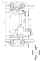
- FIG. 1 is a top view showing a schematic structure of a front lower part of a vehicle according to an embodiment of the present invention.
- FIG. 2 is a right side view schematically showing the structure of the lower front portion of the vehicle according to the present embodiment.
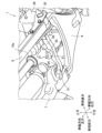
- FIG. 2 is a perspective view showing a schematic structure of the lower right front portion of the vehicle according to the present embodiment.
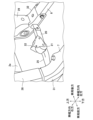
- FIG. 2 is a perspective view showing the structure of a shaft support bracket and a fixing portion thereof in the present embodiment;
- FIG. 2 is an explanatory diagram showing a transmission path of an impact load at the front of the vehicle during a frontal collision.
- FIG. 2 is an explanatory diagram showing a collapsed state of the front part of the vehicle at the time of a frontal collision.
- FIG. 1 is a top view showing a schematic structure of the front lower part of a vehicle 1 according to an embodiment of the present invention.
- FIG. 2 is a right side view showing a schematic structure of the front lower part of the vehicle 1 according to the present embodiment.
- FIG. 3 is a perspective view showing a schematic structure of the lower right front portion of the vehicle 1 according to the present embodiment. Note that FIG. 3 is a diagram of the right front lower part of the vehicle 1 viewed from below.
- FIG. 4 is a perspective view showing the structure of the shaft support bracket 20 (support member) and its fixing part in this embodiment, and is a view of the shaft support bracket 20 viewed from the upper left front.
- a vehicle 1 that employs the undercarriage structure of the present invention has various body frames such as side members 2a, 2b, such as a pickup truck.
- the vehicle 1 is also a four-wheel drive vehicle, and is equipped with a front differential 5 (front differential device) at the front and a rear differential (rear differential device) (not shown) at the rear.
- the vehicle 1 includes a pair of side members 2a and 2b that extend in the longitudinal direction of the vehicle and are spaced apart from each other in the vehicle width direction. Further, the pair of side members 2a and 2b are connected by a plurality of cross members.
- the front of the vehicle 1 is provided with a first suspension cross member 7 (first cross member) and a second suspension cross member 8 (second cross member) spaced apart from each other in the vehicle longitudinal direction.
- the first suspension cross member 7 and the second suspension cross member 8 extend in the vehicle width direction below the side members 2a, 2b, with both ends extending upward and fixed to the left and right side members 2a, 2b.
- the front ends of the suspension arms 9 are supported on both ends of the first suspension cross member 7 at the front of the vehicle.
- the rear ends of the suspension arms 9 are supported on both ends of the second suspension cross member 8 at the rear of the vehicle.
- the suspension arm 9 rotatably supports a front drive shaft 15 that drives the front wheels.
- the front drive shaft 15 is disposed at a longitudinal position of the vehicle between the first suspension cross member 7 and the second suspension cross member 8, and extends in the vehicle width direction.
- the front drive shaft 15 includes a right front drive shaft 15a that connects the front differential 5 and the right front wheel of the vehicle 1, and a left front drive shaft 15b that connects the front differential 5 and the left front wheel of the vehicle 1. .
- the right front drive shaft 15a is supported by a right suspension arm 9 supported at the lower portions of the first suspension cross member 7 and the second suspension cross member 8 near the right end portions thereof.
- the left front drive shaft 15b is supported by a left suspension arm (not shown) that is supported at the lower portions of the first suspension cross member 7 and the second suspension cross member 8 near the left ends thereof.
- the front differential 5 of the vehicle of this embodiment is arranged offset to the left from the center position in the vehicle width direction between the left and right side members 2a and 2b.
- the front portion of the front differential 5 is supported near the left end of the first suspension cross member 7 via an arm 18 extending toward the front of the vehicle so as to be swingable in the vertical direction.
- the rear part of the front differential 5 is elastically supported by the left part of the second suspension cross member 8 via an elastic member 19 so as to be movable in the vertical direction.
- this embodiment includes a shaft support bracket 20 that supports the right front drive shaft 15a.
- the shaft support bracket 20 has a hollow box-like cross section, for example, and extends in the longitudinal direction of the vehicle, and its front end is supported near the right end of the first suspension cross member 7, while its rear end is supported near the right end of the first suspension cross member 7. It is supported near the right end of 8.
- the shaft support bracket 20 supports the right front drive shaft 15a via an elastic member 21 and a connecting member 22 at a substantially central portion thereof in the longitudinal direction.
- the connecting member 22 is supported by the shaft support bracket 20 at a lower front position from the right front drive shaft 15a.
- the left and right front drive shafts 15a and 15b are rotatably housed inside a cylindrical shaft case, and the shaft case is supported by the connecting member 22 and the left and right suspension arms 9, and the front differential 5 is fixed in the case.
- a recessed portion 25 (weak portion) is provided at the front portion of the shaft support bracket 20, that is, at a portion between the support portion of the elastic member 21 and the first suspension cross member 7.
- the recess 25 is formed so that the upper surface of the shaft support bracket 20 is depressed downward. Further, as shown in FIG. 2, when viewed from the right side in the vehicle width direction, the recess 25 is disposed below the vehicle-mounted equipment 26, such as a motor, located above the shaft support bracket 20.
- both ends of the first suspension cross member 7 each have a vertical member 28 extending upward.
- both ends of the second suspension cross member 8 each have a vertical member 29 extending upward.
- the upper ends of the right vertical members 28, 29 are connected to the right side member 2a, and the upper ends of the left vertical members 28, 29 are connected to the left side member 2b.
- both ends of the portion extending in the vehicle width direction and the lower part of the vertical member 28 are vertically connected or bent, and there is a structure that covers the upper surface and front and rear surfaces of the connected or bent portion.
- a reinforcing member 31 (reinforcing portion) is provided.
- both ends of the portion extending in the vehicle width direction and the lower part of the vertical member 29 are vertically connected or bent, and cover the upper surface and front and rear surfaces of the connected portion or bent portion.
- a reinforcing member 32 like this is provided.
- Both ends of the shaft support bracket 20 are connected to a reinforcing member 31 on the right side of the vehicle of the first suspension cross member 7 and a reinforcing member 32 on the right side of the vehicle of the second suspension cross member 8.
- Figure 5 is an explanatory diagram showing the transmission path of the impact load at the front of the vehicle during a frontal collision.
- Figure 6 is an explanatory diagram showing the crushed state of the front of the vehicle during a frontal collision.
- Figures 5 and 6 are right side views showing the general structure of the front lower part of the vehicle.
- the front differential 5 is arranged offset to the left side in the vehicle width direction from the center position in the vehicle width direction. Further, a first suspension cross member 7 and a second suspension cross member 8 are provided before and after the front differential 5 and the front drive shaft 15. Further, the front portion of the front differential 5 is connected to the first suspension cross member 7 via an arm 18, and the rear portion of the front differential 5 is connected to the second suspension cross member 8. Therefore, in the left front portion of the vehicle, the front differential 5 together with the arm 18 has a structure in which the first suspension cross member 7 and the second suspension cross member 8 are connected. As a result, the strength of the left front portion of the vehicle is relatively high.
- a shaft support bracket 20 that supports the front drive shaft 15 is connected to the first suspension cross member 7 and the second suspension cross member 8. Therefore, in the right front portion of the vehicle, the shaft support bracket 20 has a structure in which the first suspension cross member 7 and the second suspension cross member 8 are connected.
- the strength of the right front portion of the vehicle is improved.
- the load applied rearward from the colliding object OS to the front end of the side member 2a will cause the side member 2a to move rearward.
- a portion of the power is transmitted from the side member 2a on the front side of the front drive shaft 15 to the rear of the side member 2a via the vertical member 28, shaft support bracket 20, and vertical member 29. That is, the collision load applied to the right front portion of the vehicle is distributed and received by the shaft support bracket 20 together with the side member 2a near the front and rear positions of the front drive shaft 15.
- the shaft support bracket 20 also has a recess 25, which is a weak part that is more easily bent than the front and rear parts. This allows the shaft support bracket 20 to buckle and absorb the collision load during a frontal collision.
- the strength of the shaft support bracket 20 can also be easily adjusted, making it easy to set the strength of the left and right sides of the front of the vehicle in the vehicle width direction uniform.
- the recessed portion 25 is provided on the upper surface of the shaft support bracket 20, as shown in FIG. can be buckled by bending it downward.
- a vehicle-mounted device 26 is provided above and adjacent to the shaft support bracket 20, and the recess 25 is recessed downward, which is a direction away from the vehicle-mounted device 26.
- the recessed portion 25 can be formed in the shaft support bracket 20 so as to be spaced apart from the vehicle-mounted equipment 26. Therefore, in the event of a frontal collision of the vehicle, the vehicle-mounted equipment 26 disposed above and adjacent to the shaft support bracket 20 can buckle the shaft support bracket 20 without getting in the way and absorb the collision load.
- vehicle-mounted equipment 26 such as a travel drive motor is arranged above the shaft support bracket 20, it is necessary to avoid the vehicle-mounted equipment 26 when the shaft support bracket 20 buckles during a frontal vehicle collision. By bending downward, the relatively expensive vehicle-mounted equipment 26 can be protected.
- reinforcing members 31 and 32 are provided at the ends of the first suspension cross member 7 and the second suspension cross member 8, and the shaft support bracket 20 is connected to the reinforcing members 31 and 32.
- the shaft support bracket 20 can be connected to a position of high strength in the first suspension cross member 7 and the second suspension cross member 8, and the strength of the connection portion of the shaft support bracket 20 can be ensured.
- the right front drive shaft 15a is supported by the shaft support bracket 20 via the elastic member 21 and the connection member 22, and in the shaft support bracket 20, the recess 25 is the connection point (support point) with the connection member 22. It is located closer to the front of the vehicle.
- the intermediate portion of the shaft support bracket 20 is supported by the connecting member 22, and the shaft support bracket 20 is easily bent in the recess 25.
- the connecting position of the connecting member 22 and the shaft support bracket 20 is located at the lower front of the vehicle with respect to the axis of the right front drive shaft 15a.
- the inertial force of the front drive shaft 15 and the front differential 5, which tend to move forward relative to the vehicle body frame such as the side members 2a, 2b, is absorbed by the shaft support via the connecting member 22. It can be efficiently received by the bracket 20, and the impact resistance of the support portion between the front drive shaft 15 and the shaft support bracket 20 can be improved, and movement of the front drive shaft 15 and the like can be suppressed.
- the present invention is not limited to the above-described embodiments.
- the detailed structures of various components such as the shaft support bracket 20 may be changed as appropriate.
- the front differential 5 is arranged on the left side of the vehicle 1 in the vehicle width direction, and the shaft support bracket 20 is arranged on the right side in the vehicle width direction, but the arrangement may be reversed.
- the shaft support brackets 20 may be arranged on the left and right sides of the front differential 5 in the vehicle width direction, so that both the first suspension cross member 7 and It may be arranged so as to be connected to the second suspension cross member 8. Even if the front differential 5 is located at the center of the vehicle 1 in the vehicle width direction, in the case of a vehicle where the strength of the left and right sides of the front part of the vehicle is different, the shaft support bracket 20 is appropriately arranged to eliminate the difference in strength between the left and right sides. can be done.
- the shaft support bracket 20 is attached to the first suspension cross member 7 and the second suspension cross member 7.
- the strength of the vehicle body between the first suspension cross member 7 and the second suspension cross member 8 can be improved.
- the present invention can be widely applied to vehicles having a frame structure including the first suspension cross member 7 and the second suspension cross member 8.
Landscapes
- Engineering & Computer Science (AREA)
- Chemical & Material Sciences (AREA)
- Combustion & Propulsion (AREA)
- Transportation (AREA)
- Mechanical Engineering (AREA)
- Body Structure For Vehicles (AREA)
Abstract
車両前後方向に延びる左右のサイドメンバ2a、2bと、車両の前後方向に互いに離間して車幅方向に延び、左右のサイドメンバ2a、2bに連結された第1サスクロスメンバ7及び第2サスクロスメンバ8と、を有し、車両の前輪を駆動するフロントドライブシャフト15が、第1サスクロスメンバ7と第2サスクロスメンバ8との間を車幅方向に延びるように配置された車両の下部構造であって、車両前後方向に延び、右フロントドライブシャフト15aを支持する支持ブラケット20を、第1サスクロスメンバ7と第2サスクロスメンバ8とを連結するように備えた。
Description
本発明は、車両のドライブシャフトの支持部の構造に関する。
ピックアップトラック等の4輪駆動車や前輪駆動車には、車両の前部にデフレンシャル装置(フロントデフ)が備えられている。
例えば特許文献1に記載された車両は、車体に搭載されたエンジンから変速機(自動変速機構部)、センタデフ(トランスファ装置)に動力が伝達し、センタデフにおいて車両前輪側及び後輪側に動力が分割される。センタデフからリヤプロペラシャフト(プロペラシャフト)を介して車両後部に設けられたリヤデフに動力が伝達される一方、フロントプロペラシャフト(ドライブピニオンシャフト)を介して車両前部に設けられたフロントデフに動力が伝達される。
例えば特許文献1に記載された車両は、車体に搭載されたエンジンから変速機(自動変速機構部)、センタデフ(トランスファ装置)に動力が伝達し、センタデフにおいて車両前輪側及び後輪側に動力が分割される。センタデフからリヤプロペラシャフト(プロペラシャフト)を介して車両後部に設けられたリヤデフに動力が伝達される一方、フロントプロペラシャフト(ドライブピニオンシャフト)を介して車両前部に設けられたフロントデフに動力が伝達される。
フロントデフは、左右前輪の間に配置されており、フロントプロペラシャフトから伝達されてきた動力を分割し、左右前輪間を車幅方向に延びる右フロントドライブシャフトを介して右前輪に動力を伝達する一方、左フロントドライブシャフトを介して左前輪に動力を伝達する構造になっている。
なお、特許文献1では、フロントデフと変速機は、車体に固定されたケースに内蔵されている。また、フロントデフは、車幅方向中央位置よりも車幅方向に偏った位置に配置されている。
なお、特許文献1では、フロントデフと変速機は、車体に固定されたケースに内蔵されている。また、フロントデフは、車幅方向中央位置よりも車幅方向に偏った位置に配置されている。
ところで、フレーム構造の車両の多くには、左右のフロントドライブシャフトの前後位置に、車幅方向に延びるサスクロスメンバが備えられている。サスクロスメンバの左右端部は左右のサイドメンバに連結されており、左右端部付近において前輪を支持するサスペンションアームが支持されている。
このように、2本のサスクロスメンバを有する車両において、フロントデフがトランスミッションとは別体に配置されている場合には、フロントデフケースが2本のサスクロスメンバを連結するように固定されている場合が多い。
しかしながら、フロントデフが車幅方向中央位置よりも車幅方向に偏った位置でサスクロスメンバを連結していると、車両前突時にフロントデフが前側のサスクロスメンバに作用した荷重を受けるため、車両の左右で強度が異なる構造になってしまう。したがって、オフセット衝突時に左右で耐衝突性能が異ならないように、強度部材の強度や構造等を調整した設計にしなければならず、設計、部品コストの増加を招くといった問題点がある。
本発明はこのような問題を解決するためになされたもので、耐衝突性能の優れた車両の下部構造を提供することを目的とする。
上記目的を達成するため、本発明の車両の下部構造は、車両の車幅方向に互いに離間して車両前後方向に延びる左右のサイドメンバと、前記車両の前後方向に互いに離間して車幅方向に延び、前記左右のサイドメンバに連結された第1クロスメンバ及び第2クロスメンバと、を有し、前記車両の前輪を駆動するドライブシャフトが、前記第1クロスメンバと前記第2クロスメンバとの間を車幅方向に延びるように配置された車両の下部構造であって、車両前後方向に延び、前記ドライブシャフトを支持する支持部材を、前記第1クロスメンバと前記第2クロスメンバとを連結するように備えたことを特徴とする。
これにより、第1クロスメンバと第2クロスメンバとを連結する支持部材を備えることで、車両前突時にサイドメンバの前部から伝達する衝突荷重をサイドメンバとともに支持部材によって受けることができる。
これにより、第1クロスメンバと第2クロスメンバとを連結する支持部材を備えることで、車両前突時にサイドメンバの前部から伝達する衝突荷重をサイドメンバとともに支持部材によって受けることができる。
好ましくは、前記ドライブシャフトに介装され、前記車両の左右前輪の差動を許容するフロントデファレンシャル装置が、車幅方向中央位置よりも車幅方向一方側に偏った位置で前記第1クロスメンバ及び第2クロスメンバに連結され、前記支持部材は、前記車幅方向中央位置よりも車幅方向他方側に偏った位置で前記第1クロスメンバ及び第2クロスメンバに連結されるとよい。
これにより、車両前部における車幅方向一方側では、フロントデファレンシャル装置が第1クロスメンバと第2クロスメンバとを連結した構造になっているので、車両前部の車幅方向一方側の部分の強度を向上させることができる。また、車両前部における車幅方向他方側の部位では、支持部材が第1クロスメンバと第2クロスメンバとを連結した構造になっているので、車両前部の車幅方向他方側の部分の強度を向上させることができる。
したがって、車両前部の車幅方向右側と車幅方向左側の強度差を減少させ、車両前側の耐オフセット衝突性能を左右均一にすることができる。
これにより、車両前部における車幅方向一方側では、フロントデファレンシャル装置が第1クロスメンバと第2クロスメンバとを連結した構造になっているので、車両前部の車幅方向一方側の部分の強度を向上させることができる。また、車両前部における車幅方向他方側の部位では、支持部材が第1クロスメンバと第2クロスメンバとを連結した構造になっているので、車両前部の車幅方向他方側の部分の強度を向上させることができる。
したがって、車両前部の車幅方向右側と車幅方向左側の強度差を減少させ、車両前側の耐オフセット衝突性能を左右均一にすることができる。
好ましくは、前記支持部材に、前後の部位よりも屈曲し易い脆弱部が備えられているとよい。
これにより、車両前突時に支持部材を座屈させて、衝突荷重を吸収させることができる。また、支持部材の強度を容易に調整することができ、車両前部の車幅方向左右の強度を容易に均一に設定することができる。
これにより、車両前突時に支持部材を座屈させて、衝突荷重を吸収させることができる。また、支持部材の強度を容易に調整することができ、車両前部の車幅方向左右の強度を容易に均一に設定することができる。
好ましくは、前記脆弱部は、前記支持部材の上面に形成されているとよい。
これにより、車両前突時に支持部材に後方に向かって荷重が作用した場合に、支持部材を下方に折り曲げるように座屈させて、衝突荷重を吸収することができる。
これにより、車両前突時に支持部材に後方に向かって荷重が作用した場合に、支持部材を下方に折り曲げるように座屈させて、衝突荷重を吸収することができる。
好ましくは、前記支持部材に隣接して車両搭載機器を備え、前記脆弱部が前記車両搭載機器から離れる方向に向かって凹状に形成されているとよい。
これにより、支持部材に車両搭載機器と間隔を設けて脆弱部を形成することができる。したがって、車両前突時に支持部材に荷重が作用して座屈した場合に、支持部材が脆弱部において車両搭載機器から離れるように折り曲げられて、支持部材と車両搭載機器との干渉が抑制され、車両搭載機器の保護を図ることができる。
これにより、支持部材に車両搭載機器と間隔を設けて脆弱部を形成することができる。したがって、車両前突時に支持部材に荷重が作用して座屈した場合に、支持部材が脆弱部において車両搭載機器から離れるように折り曲げられて、支持部材と車両搭載機器との干渉が抑制され、車両搭載機器の保護を図ることができる。
好ましくは、前記第1クロスメンバ及び前記第2クロスメンバは端部に補強部を有し、前記支持部材は、前記第1クロスメンバ及び前記第2クロスメンバの前記端部に連結されているとよい。
これにより、第1クロスメンバ及び第2クロスメンバにおける強度の高い箇所に支持部材を連結させることができ、車両前部の車幅方向一方側の強度を更に向上させることができる。
これにより、第1クロスメンバ及び第2クロスメンバにおける強度の高い箇所に支持部材を連結させることができ、車両前部の車幅方向一方側の強度を更に向上させることができる。
好ましくは、前記ドライブシャフトと前記支持部材とを連結する連結部材を備え、前記脆弱部は、前記支持部材の前記連結部材との連結箇所より車両前方に設けられているとよい。
これにより、車両前突時に支持部材に荷重が作用して座屈した場合に、支持部材が脆弱部において折り曲げられ易くなる。
これにより、車両前突時に支持部材に荷重が作用して座屈した場合に、支持部材が脆弱部において折り曲げられ易くなる。
好ましくは、前記連結部材と前記支持部材との連結位置は、前記ドライブシャフトの軸線に対して車両前側下方に位置するとよい。
これにより、車両前突時に、ドライブシャフト及びフロントデファレンシャル装置の慣性力をアームを介して支持部材に効率よく受け止めることができ、ドライブシャフトと支持部材との支持部の耐衝撃性を向上させることができる。
これにより、車両前突時に、ドライブシャフト及びフロントデファレンシャル装置の慣性力をアームを介して支持部材に効率よく受け止めることができ、ドライブシャフトと支持部材との支持部の耐衝撃性を向上させることができる。
本発明の車両の下部構造によれば、車両前突時にサイドメンバの前部から伝達する衝突荷重をサイドメンバとともに支持部材によって受けることができ、支持部材を配置した位置での車両前突に対する強度を向上させることができる。
以下、図面に基づき本発明の実施形態について説明する。
図1は、本発明の一実施形態の車両1の前下部の概略構造を示す上面図である。図2は、本実施形態に係る車両1の前下部の概略構造を示す右側面図である。図3は、本実施形態に係る車両1の右前下部の概略構造を示す斜視図である。なお、図3は、車両1の右前下部を下方から見た図である。図4は、本実施形態におけるシャフト支持ブラケット20(支持部材)及びその固定部の構造を示す斜視図であり、シャフト支持ブラケット20を左前上方から視た図である。
図1は、本発明の一実施形態の車両1の前下部の概略構造を示す上面図である。図2は、本実施形態に係る車両1の前下部の概略構造を示す右側面図である。図3は、本実施形態に係る車両1の右前下部の概略構造を示す斜視図である。なお、図3は、車両1の右前下部を下方から見た図である。図4は、本実施形態におけるシャフト支持ブラケット20(支持部材)及びその固定部の構造を示す斜視図であり、シャフト支持ブラケット20を左前上方から視た図である。
本発明の下部構造を採用する車両1は、例えばピックアップトラックのように、サイドメンバ2a、2b等の各種の車体フレームを有する。また、車両1は、4輪駆動車であり、前部にフロントデフ5(フロントデファレンシャル装置)、後部に図示しないリヤデフ(リヤデファレンシャル装置)を備えている。
図1に示すように、車両1は、車幅方向に互いに間隔をおいて車両前後方向に延びる一対のサイドメンバ2a、2bを備えている。また、一対のサイドメンバ2a、2bは、複数のクロスメンバによって連結されている。
図1~4に示すように、車両1の前部には、車両前後方向に互いに離間して、第1サスクロスメンバ7(第1クロスメンバ)と、第2サスクロスメンバ8(第2クロスメンバ)と、が備えられている。第1サスクロスメンバ7及び第2サスクロスメンバ8は、サイドメンバ2a、2bの下方位置を車幅方向に延び両端部が上方に延びて左右のサイドメンバ2a、2bに固定されている。
車両前側の第1サスクロスメンバ7の両端部には、夫々サスペンションアーム9の前端部が支持されている。車両後側の第2サスクロスメンバ8の両端部には、夫々サスペンションアーム9の後端部が支持されている。
サスペンションアーム9は、前輪を駆動するフロントドライブシャフト15を回転可能に支持している。フロントドライブシャフト15は、第1サスクロスメンバ7と第2サスクロスメンバ8との間の車両前後位置に配置され、車幅方向に延びている。
フロントドライブシャフト15は、フロントデフ5と車両1の右前輪とを連結する右フロントドライブシャフト15aと、フロントデフ5と車両1の左前輪とを連結する左フロントドライブシャフト15bとを有している。
右フロントドライブシャフト15aは、第1サスクロスメンバ7及び第2サスクロスメンバ8の右端部付近の下部に支持された右側のサスペンションアーム9に支持されている。左フロントドライブシャフト15bは、第1サスクロスメンバ7及び第2サスクロスメンバ8の左端部付近の下部に支持された図示しない左側のサスペンションアームに支持されている。
本実施形態の車両のフロントデフ5は、左右のサイドメンバ2a、2bの間で車幅方向中央位置より左側にオフセットして配置されている。
フロントデフ5の前部は、車両前方に延びるアーム18を介して第1サスクロスメンバ7の左端部付近に上下方向に揺動可能に支持されている。
フロントデフ5の前部は、車両前方に延びるアーム18を介して第1サスクロスメンバ7の左端部付近に上下方向に揺動可能に支持されている。
フロントデフ5の後部は、第2サスクロスメンバ8の左部に弾性部材19を介して上下方向に移動可能に弾性支持されている。
更に、本実施形態では、右フロントドライブシャフト15aを支持するシャフト支持ブラケット20を備えている。シャフト支持ブラケット20は、例えば断面が中空箱状であって、車両前後方向に延び、前端部が第1サスクロスメンバ7の右端部付近に支持される一方、後端部が第2サスクロスメンバ8の右端部付近に支持されている。
更に、本実施形態では、右フロントドライブシャフト15aを支持するシャフト支持ブラケット20を備えている。シャフト支持ブラケット20は、例えば断面が中空箱状であって、車両前後方向に延び、前端部が第1サスクロスメンバ7の右端部付近に支持される一方、後端部が第2サスクロスメンバ8の右端部付近に支持されている。
シャフト支持ブラケット20は、その前後方向略中央部において、弾性部材21及び連結部材22を介して右フロントドライブシャフト15aを支持している。連結部材22は、右フロントドライブシャフト15aから前下方の位置でシャフト支持ブラケット20に支持されている。
なお、左右のフロントドライブシャフト15a、15bは、筒状のシャフトケースの内部に回転可能に収納されており、当該シャフトケースが連結部材22や左右のサスペンションアーム9に支持されるともに、フロントデフ5のケースに固定されている。
シャフト支持ブラケット20の前部、即ち弾性部材21の支持部と第1サスクロスメンバ7との間の部位には、凹部25(脆弱部)が設けられている。凹部25は、シャフト支持ブラケット20の上面を下方に凹むようにして形成されている。また、図2に示すように車幅方向右方から見て、凹部25はシャフト支持ブラケット20の上方に位置するモータ等の車両搭載機器26の下方に配置されている。
また、第1サスクロスメンバ7の両端部は、上方に延びる縦部材28を夫々有している。また、第2サスクロスメンバ8の両端部は、上方に延びる縦部材29を夫々有している。
右側の縦部材28、29の上端部は右サイドメンバ2aに接続され、左側の縦部材28、29の上端部は左サイドメンバ2bに接続されている。
右側の縦部材28、29の上端部は右サイドメンバ2aに接続され、左側の縦部材28、29の上端部は左サイドメンバ2bに接続されている。
第1サスクロスメンバ7において、車幅方向に延びる部位の両端部と縦部材28の下部とは、垂直に接続あるいは屈曲しており、当該接続部あるいは屈曲部の上面及び前後面を覆うような補強部材31(補強部)が設けられている。
また、第2サスクロスメンバ8において、車幅方向に延びる部位の両端部と縦部材29の下部とは、垂直に接続あるいは屈曲しており、当該接続部あるいは屈曲部の上面及び前後面を覆うような補強部材32が設けられている。
また、第2サスクロスメンバ8において、車幅方向に延びる部位の両端部と縦部材29の下部とは、垂直に接続あるいは屈曲しており、当該接続部あるいは屈曲部の上面及び前後面を覆うような補強部材32が設けられている。
シャフト支持ブラケット20の両端部は、第1サスクロスメンバ7の車両右側の補強部材31と、第2サスクロスメンバ8の車両右側の補強部材32に接続されている。
図5は、前突時における車両前部の衝撃荷重の伝達経路を示す説明図である。図6は、前突時において車両前部の潰れた状態を示す説明図である。なお。図5、6は、車両の前下部の概略構造を示す右側面図である。
以上のように、本実施形態の車両1は、フロントデフ5が車幅方向中央位置よりも車幅方向左方側にオフセットして配置されている。また、フロントデフ5及びフロントドライブシャフト15の前後には、第1サスクロスメンバ7及び第2サスクロスメンバ8が備えられている。更に、フロントデフ5の前部はアーム18を介して第1サスクロスメンバ7に接続されており、フロントデフ5の後部は第2サスクロスメンバ8に接続されている。したがって、車両左前部においては、アーム18とともにフロントデフ5が第1サスクロスメンバ7と第2サスクロスメンバ8とを連結した構造になっている。これにより、車両左前部の強度が比較的高いものになっている。
一方、車両右前部においては、フロントドライブシャフト15を支持するシャフト支持ブラケット20が第1サスクロスメンバ7及び第2サスクロスメンバ8に接続されている。したがって、車両右前部においては、シャフト支持ブラケット20が第1サスクロスメンバ7と第2サスクロスメンバ8とを連結した構造になっている。
シャフト支持ブラケット20によって第1サスクロスメンバ7と第2サスクロスメンバ8とを連結することで、車両右前部の強度が向上する。例えば図5中の矢印に示すように、車両の右前部にオフセット衝突した場合では、衝突物OSからサイドメンバ2aの前端部に後方に向かって受けた荷重は、サイドメンバ2aを後方に向かって伝達するが、その一部がフロントドライブシャフト15の前側でサイドメンバ2aから縦部材28、シャフト支持ブラケット20、縦部材29を介してサイドメンバ2aの後部に伝達する。即ち、車両右前部に受けた衝突荷重は、フロントドライブシャフト15の前後位置付近で、サイドメンバ2aとともにシャフト支持ブラケット20が分散して受けることになる。
なお、車両1の左前部にオフセット衝突した場合では、衝突物OSからサイドメンバ2bの前部に後方に向かって受けた荷重の一部は、フロントドライブシャフト15の前側でサイドメンバ2aから縦部材28、アーム18、フロントデフ5、縦部材29を介してサイドメンバ2aの後部に伝達する。即ち、車両左前部に受けた衝突荷重は、フロントドライブシャフト15の前後位置付近で、サイドメンバ2aとともにアーム18及びフロントデフ5が分散して受けることになる。
これにより、フロントデフ5が車幅方向左方にオフセットして配置された車両であっても、車両右前部と車両左前部とのオフセット衝突荷重に対する強度や衝撃吸収性を略同一にして、耐オフセット衝突性能を左右均一にすることが可能になる。
また、シャフト支持ブラケット20には、前後の部位よりも屈曲し易い脆弱部である凹部25が備えられている。これにより、車両前突時にシャフト支持ブラケット20を座屈させて、衝突荷重を吸収させることができる。また、シャフト支持ブラケット20の強度を容易に調整することができ、車両前部の車幅方向左右の強度を容易に均一に設定することができる。
また、この凹部25はシャフト支持ブラケット20の上面に設けられているので、図6に示すように、車両前突時にシャフト支持ブラケット20に後方に向かって荷重が作用した場合に、シャフト支持ブラケット20を下方に折り曲げるように座屈させることができる。
また、シャフト支持ブラケット20の上方に隣接して車両搭載機器26が備えられており、凹部25は、車両搭載機器26から離れる方向である下方に向かって凹んだ形状である。これにより、シャフト支持ブラケット20に車両搭載機器26と間隔を設けて凹部25を形成することができる。
したがって、車両前突時にシャフト支持ブラケット20の上方に隣接して配置された車両搭載機器26が邪魔にならずにシャフト支持ブラケット20を座屈させて、衝突荷重を吸収することができる。
したがって、車両前突時にシャフト支持ブラケット20の上方に隣接して配置された車両搭載機器26が邪魔にならずにシャフト支持ブラケット20を座屈させて、衝突荷重を吸収することができる。
シャフト支持ブラケット20の上方に、走行駆動用のモータ等の車両搭載機器26が配置されている場合には、車両前突時にシャフト支持ブラケット20が座屈した場合に、車両搭載機器26を避けるように下方に屈曲することで、比較的高価な車両搭載機器26の保護を図ることができる。
また、第1サスクロスメンバ7及び第2サスクロスメンバ8の端部には補強部材31、32が設けられており、シャフト支持ブラケット20は補強部材31、32に連結されている。これにより、第1サスクロスメンバ7及び第2サスクロスメンバ8における強度の高い位置にシャフト支持ブラケット20を連結させることができ、シャフト支持ブラケット20の連結部の強度を確保することができる。
また、右フロントドライブシャフト15aは、弾性部材21及び連結部材22を介してシャフト支持ブラケット20に支持されているが、シャフト支持ブラケット20において、凹部25は連結部材22との連結箇所(支持箇所)より車両前方に設けられている。
これにより、車両前突時に第1サスクロスメンバ7側から車両後方に向かってシャフト支持ブラケット20に荷重が作用した場合に、シャフト支持ブラケット20の中間部分が連結部材22に支持され、シャフト支持ブラケット20が凹部25において折り曲げられ易くなる。
これにより、車両前突時に第1サスクロスメンバ7側から車両後方に向かってシャフト支持ブラケット20に荷重が作用した場合に、シャフト支持ブラケット20の中間部分が連結部材22に支持され、シャフト支持ブラケット20が凹部25において折り曲げられ易くなる。
また、連結部材22とシャフト支持ブラケット20との連結位置は、右フロントドライブシャフト15aの軸線に対して車両前下方に位置している。
これにより、車両前突時に、サイドメンバ2a、2b等の車体フレームに対して相対的に前方に移動しようとするフロントドライブシャフト15及びフロントデフ5の慣性力を、連結部材22を介してシャフト支持ブラケット20に効率よく受け止めることができ、フロントドライブシャフト15とシャフト支持ブラケット20との支持部の耐衝撃性を向上させることができるとともに、フロントドライブシャフト15等の移動を抑制することができる。
これにより、車両前突時に、サイドメンバ2a、2b等の車体フレームに対して相対的に前方に移動しようとするフロントドライブシャフト15及びフロントデフ5の慣性力を、連結部材22を介してシャフト支持ブラケット20に効率よく受け止めることができ、フロントドライブシャフト15とシャフト支持ブラケット20との支持部の耐衝撃性を向上させることができるとともに、フロントドライブシャフト15等の移動を抑制することができる。
本発明は、上記の実施形態に限定するものではない。
例えば、シャフト支持ブラケット20等の各種部品の詳細な構造は適宜変更してもよい。
例えば、シャフト支持ブラケット20等の各種部品の詳細な構造は適宜変更してもよい。
また、本実施形態では、フロントデフ5が車両1の車幅方向左側に配置され、シャフト支持ブラケット20が車幅方向右側に配置されているが、逆に配置してもよい。
あるいは、フロントデフ5が車両1の車幅方向中央部に位置していても、シャフト支持ブラケット20をフロントデフ5の車幅方向左右側に夫々配置して、いずれも第1サスクロスメンバ7及び第2サスクロスメンバ8に連結するように配置してもよい。
フロントデフ5が車両1の車幅方向中央部に位置していたとしても、車両前部の左右の強度が異なる車両の場合には、シャフト支持ブラケット20を適宜配置して左右の強度差を解消させることができる。
フロントデフ5が車両1の車幅方向中央部に位置していたとしても、車両前部の左右の強度が異なる車両の場合には、シャフト支持ブラケット20を適宜配置して左右の強度差を解消させることができる。
あるいは、フロントデフ5が車両1の車幅方向中央部に位置し耐オフセット衝突に対する左右の均一性を有している車両であっても、シャフト支持ブラケット20を第1サスクロスメンバ7及び第2サスクロスメンバ8に連結することで、第1サスクロスメンバ7及び第2サスクロスメンバ8間の車体の強度を向上させることができる。
また、本発明は第1サスクロスメンバ7及び第2サスクロスメンバ8を有するフレーム構造の車両に広く適用することができる。
また、本発明は第1サスクロスメンバ7及び第2サスクロスメンバ8を有するフレーム構造の車両に広く適用することができる。
1 車両
2a、2b サイドメンバ
5 フロントデフ(フロントデファレンシャル装置)
7 第1サスクロスメンバ(第1クロスメンバ)
8 第2サスクロスメンバ(第2クロスメンバ)
15a 右フロントドライブシャフト(ドライブシャフト)
20 シャフト支持ブラケット(支持部材)
22 連結部材
25 凹部(脆弱部)
26 車両搭載機器
31 補強部材(補強部)
2a、2b サイドメンバ
5 フロントデフ(フロントデファレンシャル装置)
7 第1サスクロスメンバ(第1クロスメンバ)
8 第2サスクロスメンバ(第2クロスメンバ)
15a 右フロントドライブシャフト(ドライブシャフト)
20 シャフト支持ブラケット(支持部材)
22 連結部材
25 凹部(脆弱部)
26 車両搭載機器
31 補強部材(補強部)
Claims (8)
- 車両の車幅方向に互いに離間して車両前後方向に延びる左右のサイドメンバと、
前記車両の前後方向に互いに離間して車幅方向に延び、前記左右のサイドメンバに連結された第1クロスメンバ及び第2クロスメンバと、を有し、
前記車両の前輪を駆動するドライブシャフトが、前記第1クロスメンバと前記第2クロスメンバとの間を車幅方向に延びるように配置された車両の下部構造であって、
車両前後方向に延び、前記ドライブシャフトを支持する支持部材を、前記第1クロスメンバと前記第2クロスメンバとを連結するように備えた
ことを特徴とする車両の下部構造。 - 前記ドライブシャフトに介装され、前記車両の左右前輪の差動を許容するフロントデファレンシャル装置が、車幅方向中央位置よりも車幅方向一方側に偏った位置で前記第1クロスメンバ及び第2クロスメンバに連結され、
前記支持部材は、前記車幅方向中央位置よりも車幅方向他方側に偏った位置で前記第1クロスメンバ及び第2クロスメンバに連結される
ことを特徴とする請求項1に記載の車両の下部構造。 - 前記支持部材に、前後の部位よりも屈曲し易い脆弱部が備えられている
ことを特徴とする請求項1または2に記載の車両の下部構造。 - 前記脆弱部は、前記支持部材の上面に形成されている
ことを特徴とする請求項3に記載の車両の下部構造。 - 前記支持部材に隣接して車両搭載機器を備え、
前記脆弱部が前記車両搭載機器から離れる方向に向かって凹状に形成されている
ことを特徴とする請求項3に記載の車両の下部構造。 - 前記第1クロスメンバ及び前記第2クロスメンバは端部に補強部を有し、
前記支持部材は、前記第1クロスメンバ及び前記第2クロスメンバの前記端部に連結されている
ことを特徴とする請求項2に記載の車両の下部構造。 - 前記ドライブシャフトと前記支持部材とを連結する連結部材を備え、
前記脆弱部は、前記支持部材の前記連結部材との連結箇所より車両前方に設けられている
ことを特徴とする請求項3に記載の車両の下部構造。 - 前記連結部材と前記支持部材との連結位置は、前記ドライブシャフトの軸線に対して車両前側下方に位置する
ことを特徴とする請求項7に記載の車両の下部構造。
Priority Applications (1)
| Application Number | Priority Date | Filing Date | Title |
|---|---|---|---|
| PCT/JP2022/035283 WO2024062584A1 (ja) | 2022-09-21 | 2022-09-21 | 車両の下部構造 |
Applications Claiming Priority (1)
| Application Number | Priority Date | Filing Date | Title |
|---|---|---|---|
| PCT/JP2022/035283 WO2024062584A1 (ja) | 2022-09-21 | 2022-09-21 | 車両の下部構造 |
Publications (1)
| Publication Number | Publication Date |
|---|---|
| WO2024062584A1 true WO2024062584A1 (ja) | 2024-03-28 |
Family
ID=90454035
Family Applications (1)
| Application Number | Title | Priority Date | Filing Date |
|---|---|---|---|
| PCT/JP2022/035283 WO2024062584A1 (ja) | 2022-09-21 | 2022-09-21 | 車両の下部構造 |
Country Status (1)
| Country | Link |
|---|---|
| WO (1) | WO2024062584A1 (ja) |
Citations (2)
| Publication number | Priority date | Publication date | Assignee | Title |
|---|---|---|---|---|
| JPS62189230U (ja) * | 1986-05-23 | 1987-12-02 | ||
| JPS62201129U (ja) * | 1986-06-13 | 1987-12-22 |
-
2022
- 2022-09-21 WO PCT/JP2022/035283 patent/WO2024062584A1/ja unknown
Patent Citations (2)
| Publication number | Priority date | Publication date | Assignee | Title |
|---|---|---|---|---|
| JPS62189230U (ja) * | 1986-05-23 | 1987-12-02 | ||
| JPS62201129U (ja) * | 1986-06-13 | 1987-12-22 |
Similar Documents
| Publication | Publication Date | Title |
|---|---|---|
| JP3591448B2 (ja) | 自動車の車体前部構造 | |
| EP1852331B1 (en) | Front structure of vehicle body | |
| CN110481477B (zh) | 吸能结构和具有其的车辆 | |
| KR20020049017A (ko) | 중첩을 피하기 위한 충격 흡수 구조물을 구비하는 자동차,특히 승용차 | |
| KR19990031878A (ko) | 자동차의 전륜 현가장치 | |
| WO2024062584A1 (ja) | 車両の下部構造 | |
| JP4423898B2 (ja) | 車体構造 | |
| JP2984754B2 (ja) | 自動車の下部車体構造 | |
| JP2009107441A (ja) | 車体構造 | |
| JP5399760B2 (ja) | 車体前部構造 | |
| JP3730417B2 (ja) | ディファレンシャル装置の支持構造 | |
| KR100737601B1 (ko) | 자동차의 서브프레임 | |
| JP4379991B2 (ja) | 車両用駆動伝達装置 | |
| JP3356978B2 (ja) | パワーユニットのマウント構造 | |
| JPH0747844A (ja) | 自動車のパワートレイン支持構造 | |
| JP4304464B2 (ja) | 車両の前部車体構造 | |
| US11518440B2 (en) | Vehicle front portion structure | |
| JP2005170269A (ja) | 車両の車体構造 | |
| JP2002321648A (ja) | 車両の車体構造 | |
| JP2532778Y2 (ja) | 自動車の後輪駆動装置の取付構造 | |
| JP3597028B2 (ja) | フロントデファレンシャルケースの支持構造 | |
| KR100333881B1 (ko) | 자동차 프레임 보강 구조 | |
| JP4212756B2 (ja) | キヤブオーバ型貨物車両のシヤシフレーム構造 | |
| JPH09272351A (ja) | 車両におけるリヤディファレンシャルの支持構造 | |
| KR100308955B1 (ko) | 자동차의 현가장치 |
Legal Events
| Date | Code | Title | Description |
|---|---|---|---|
| 121 | Ep: the epo has been informed by wipo that ep was designated in this application |
Ref document number: 22959548 Country of ref document: EP Kind code of ref document: A1 |