WO2024053152A1 - リールシート及び釣竿 - Google Patents
リールシート及び釣竿 Download PDFInfo
- Publication number
- WO2024053152A1 WO2024053152A1 PCT/JP2023/015742 JP2023015742W WO2024053152A1 WO 2024053152 A1 WO2024053152 A1 WO 2024053152A1 JP 2023015742 W JP2023015742 W JP 2023015742W WO 2024053152 A1 WO2024053152 A1 WO 2024053152A1
- Authority
- WO
- WIPO (PCT)
- Prior art keywords
- reel
- reel seat
- cylindrical
- nut member
- rod
- Prior art date
- Legal status (The legal status is an assumption and is not a legal conclusion. Google has not performed a legal analysis and makes no representation as to the accuracy of the status listed.)
- Ceased
Links
Images


Classifications
-
- A—HUMAN NECESSITIES
- A01—AGRICULTURE; FORESTRY; ANIMAL HUSBANDRY; HUNTING; TRAPPING; FISHING
- A01K—ANIMAL HUSBANDRY; AVICULTURE; APICULTURE; PISCICULTURE; FISHING; REARING OR BREEDING ANIMALS, NOT OTHERWISE PROVIDED FOR; NEW BREEDS OF ANIMALS
- A01K87/00—Fishing rods
- A01K87/06—Devices for fixing reels on rods
-
- A—HUMAN NECESSITIES
- A01—AGRICULTURE; FORESTRY; ANIMAL HUSBANDRY; HUNTING; TRAPPING; FISHING
- A01K—ANIMAL HUSBANDRY; AVICULTURE; APICULTURE; PISCICULTURE; FISHING; REARING OR BREEDING ANIMALS, NOT OTHERWISE PROVIDED FOR; NEW BREEDS OF ANIMALS
- A01K87/00—Fishing rods
- A01K87/08—Handgrips
Definitions
- a fishing rod reel seat and a fishing rod grip are usually placed on the rod body, and the fishing rod reel sheet includes a reel for placing the reel leg on the upper or lower side of the fishing rod body. A leg rest is formed.
- a reel seat for such a fishing rod for example, as disclosed in Patent Document 1, there is a reel seat in which the position of the reel leg mounting portion of the reel seat is offset in a downward direction with respect to the axis of the main rod rod. (also referred to as an offset reel seat) is known. According to such an offset reel seat, the reel leg rest is shifted downward, so when a round double-bearing reel is installed, even if you grip the grip on the rear side, your thumb will not move. It is disclosed that the operating position of the device does not become high, and it is possible to prevent the palm from opening and reducing operability.
- Patent Document 2 discloses a grip at the hand end, a reel seat part set at the front end of the grip to place and support a reel, and a rod (rod) provided at the front end of the reel seat part.
- a reel support member having a rod holding part for storing and holding a rear end of the fishing rod, the reel seat part extending forward from a portion adjacent to the front end of the grip;
- the reel seat section has an upper surface including a supporting portion, and a bottom surface whose cross-sectional shape has the lowest point approximately at the center and is curved upward toward both side edges of the upper surface.
- a reel support member is disclosed that substantially covers the reel in the width direction.
- the present invention has been made in view of the above circumstances, and its purpose is to adopt a structure in which the position of the reel leg mounting portion of the reel seat is offset in the downward direction with respect to the axis of the main rod rod. Even when the reel is gripped or cast, it is possible to prevent hands and fingers from touching the operating member for fixing the reel legs to the reel seat, thereby stably maintaining the reel fixed to the reel seat. To provide a reel seat and a fishing rod equipped with the same.
- a reel seat includes a reel leg placement section on which a reel leg is placed, a fixed hood provided on the axial front side of the reel leg placement section, and a reel leg placement section on which the reel leg placement section is placed.
- a reel seat main body comprising a cylindrical portion provided on the axial rear side of the reel leg mounting portion; a movable hood provided on the axial rear side of the reel leg mounting portion; a cylindrical nut member that makes the moving hood movable; and a hood portion that accommodates at least a portion of the reel leg, the nut member protruding outward in the axial direction from the axial rear end of the cylindrical portion and extending in the radial direction of the cylindrical nut member.
- an operating section configured to be able to rotate the cylindrical nut member by operating an outer surface of the cylindrical nut member; an engaged part that engages with the engaging part, and a connecting part that connects the operating part and the engaged part, and when the nut member is rotated by operation of the operating part, the movable hood is It can be moved forward in the axial direction.
- the engaging portion and the nut member are screwed together.
- a grip portion is provided on the outer surface of the cylindrical portion.
- the axial rear end of the grip portion is the axial rear end of the cylindrical portion when viewed in the axial direction of the reel leg mounting portion. and the operating portion of the nut member.
- the rod body can be inserted into the cylindrical portion from the rear side in the axial direction.
- a spacer member is provided between the inner surface of the nut member and the outer surface of the rod body.
- a stopper member is provided at the rear end in the axial direction of the operating portion of the nut member.
- the reel seat when viewed in a downward direction from the central axis of the cylindrical part in a cross section perpendicular to the axial direction of the reel leg mounting part, with the rod body inserted,
- the rod body, the engaged portion, and the cylindrical portion are provided in this order from the inside.
- the engaging portion and the engaged portion are arranged from the inside when viewed in a downward direction from the central axis of the cylindrical portion in a cross section perpendicular to the axial direction of the reel leg mounting portion.
- the joint portion and the cylindrical portion are provided in this order.
- the engaging portion is formed in an arc shape when viewed in a cross section perpendicular to the axial direction of the reel leg mounting portion.
- the angle of the circular arc is in the range of 70 degrees to 140 degrees.
- the rod body is attached to the reel seat by being inserted through a portion or the entirety of the reel seat.
- a fishing rod according to an embodiment of the present invention is configured to include any one of the above reel seats and a rod body.
- the reel leg rests when the reel is gripped or during casting operation.
- a reel seat that can stably maintain the fixed state of the reel to the reel seat by preventing hands and fingers from touching the operating member for fixing the reel to the reel seat, and a fishing rod equipped with the reel seat. It becomes possible to provide
- FIG. 1 is a diagram showing a fishing rod according to an embodiment of the present invention.
- (a) A cross-sectional view of a reel seat according to an embodiment of the present invention.
- (b) shows a front view of a reel seat according to an embodiment of the present invention.
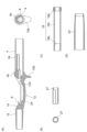
- (a) shows the structure of a reel seat main body of a reel seat according to an embodiment of the present invention.
- (b) shows the structure of a spacer member of a reel seat according to an embodiment of the present invention.
- (c) shows the structure of a nut member of a reel seat according to an embodiment of the present invention.
- (d) shows the structure of a grip portion of a reel seat according to an embodiment of the present invention.
- FIG. 3 is a diagram showing a cross section of a reel seat according to an embodiment of the present invention.
- FIG. 3 is a diagram showing a cross section of a reel seat according to an embodiment of the present invention.
- FIG. 3 is a diagram showing a cross section of a reel seat according to an embodiment of the present invention.
- FIG. 3 is a diagram showing a cross section of a reel seat according to an embodiment of the present invention.
- FIG. 3 is a diagram showing a cross section of a reel seat according to an embodiment of the present invention.
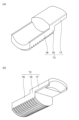
- (a) It is an upper perspective view of the moving hood in the reel seat based on one Embodiment of this invention.
- (b) It is a downward perspective view of the movable hood in the reel seat according to one embodiment of the present invention.
- (a) shows a cross-sectional view of a reel seat according to another embodiment of the present invention.
- (b) shows a front view of a reel seat according to another embodiment of the present invention.
- FIG. 1 is a diagram showing an embodiment of a fishing rod according to the present invention.
- a fishing rod 1 according to an embodiment of the present invention includes a rod body 2, a reel 6 attached to the rod body 2 via a reel seat 9, a fishing line guide 10 attached to the rod body 2, Equipped with.
- each of the reel seat 9 and the fishing line guide 10 corresponds to an attachment component that is attached to the outer peripheral surface of the rod body.
- the rod body 2 is configured by, for example, connecting a base rod 3, a middle rod 5, a tip rod 7, and the like. These rod bodies are, for example, joined in a side-by-side manner.
- the base rod 3, the middle rod 5, and the tip rod 7 may be joined by a drawing method, a reverse joint method, a spigot method, or any other known joining method.
- the rod body 2 may be composed of a single rod body.
- the base rod 3, the middle rod 5, and the tip rod 7 are made of, for example, a tubular body made of fiber-reinforced resin.
- This fiber-reinforced resin tubular body is created by winding a fiber-reinforced resin prepreg (pre-preg sheet) in which reinforcing fibers are impregnated with a matrix resin around a core metal, and heating and curing the prepreg sheet.
- a fiber-reinforced resin prepreg pre-preg sheet
- reinforcing fibers contained in this prepreg sheet carbon fibers, glass fibers, and any other known reinforcing fibers other than these can be used, for example.
- a thermosetting resin such as an epoxy resin can be used as the matrix resin contained in the prepreg sheet. After the prepreg sheet is cured, the core metal is removed. Further, the outer surface of the tubular body is polished as appropriate.
- Each rod body may be configured in a solid shape.
- the main rod 3, the middle rod 5, and the tip rod 7 are provided with a plurality of fishing line guides 10 (fishing line guides 10A to 10D) that guide the fishing line reeled out from the reel 6 attached to the reel seat 9.
- the main rod 3 is provided with a fishing line guide 10A
- the middle rod 5 is provided with a fishing line guide 10B
- the tip rod 7 is provided with a fishing line guide 10C.
- a top guide 10D is provided at the tip of the tip rod 7, but its details will be omitted.
- FIG. 2(a) shows a cross-sectional view of a reel sheet according to an embodiment of the present invention (a cross-sectional view in the vertical direction of the plane of FIG. 2(a) passing through the central axis of the reel sheet), and
- FIG. 1 is a front view of a reel seat according to an embodiment of the present invention.
- the axial direction (front-back direction) and the up-down direction mean the direction shown in FIG. 2(a)
- the left-right direction (side direction) means the direction perpendicular to the paper surface of FIG. 2(a). do.
- the front means the tip side of the fishing rod
- the rear means the base end side
- the upper side means the reel side with respect to the axis X of the main rod (pole rod) when a double-bearing reel is installed
- the lower side means the means the opposite side.
- the axis X also corresponds to the axes of the reel seat 9, the reel seat main body 12, the reel leg mounting portion 12a, and the cylindrical portion 4, and these directions can be referred to as any one of these axial directions.
- FIG. 3(a) shows the structure of a reel seat main body of a reel seat according to an embodiment of the present invention
- FIG. 3(b) shows a structure of a spacer member of a reel seat according to an embodiment of the present invention.
- FIG. 3(c) shows the structure of the nut member of the reel seat according to one embodiment of the present invention
- FIG. 4(d) shows the structure of the nut member of the reel seat according to one embodiment of the present invention. It shows the structure of the grip part of the reel seat.
- the reel seat body 12 includes a reel leg mounting surface 12a along the axial direction on which the reel leg 6a of the fishing reel 6 is mounted.
- the reel seat body 12 can be configured to have a length in the range of, for example, 150 mm to 200 mm, but is not limited thereto.
- this reel seat body 12 has the opposite side of the reel leg mounting surface 12a slightly bulged out, so that when the reel seat body 12 is gripped with the hand that is gripping it, it supports the ball of the foot or the vicinity thereof, so that it can be gripped easily.
- a bulging portion (trigger) 12b having an easily curved outer surface is formed. Note that the rod body may be connected to the front side of the reel seat body 12.
- the reel leg placement surface 12a of the reel seat body 12 is flat or substantially flat with a larger curvature than other circumferential portions (for example, the trigger 12b) adjacent to the reel leg placement surface 12a of the reel seat body 12. It is formed in a state extending in the axial direction of the reel seat main body 12 shown in FIG.
- a fixed hood 14 is integrally disposed at one end (on the rod tip side) of the reel seat body 12.
- One end of the reel leg mounting surface 12a of the reel seat body 12 is disposed inside the fixed hood 14.
- a movable hood 13 is attached to the other end (rod base side) of the reel seat body 12 so as to be movable in the axial direction.
- the fishing reel 6 is mounted by placing the reel leg 6a on the reel leg mounting portion 12a, fitting the tip side into the fixed hood 14, and tightening the rear end side with the movable hood 13 that moves in the axial direction. is attached to and fixed to the reel seat 9.
- the reel seat 9 includes the reel seat main body 12 and the movable hood 13, but may include members other than these.
- the reel seat 9 according to an embodiment of the present invention includes a reel leg mounting section 12a on which the reel leg 6a is mounted, and an axially forward side (rod tip side) of the reel leg mounting section 12a. ), a reel seat main body 12 comprising a fixed hood 14 provided on the reel leg mounting portion 12a, and a cylindrical portion 4 provided on the axial rear side (the rod bottom side) of the reel leg mounting portion 12a, and the reel leg mounting portion 12a.
- a movable hood 13 provided on the rear side in the axial direction (rod end side), and a cylindrical nut member 18 provided inside the cylindrical portion 4 to enable the movable hood 13 to move by rotation.
- the reel seat 9 is attached to a rod body (rod end side rod body) 2a, and the movable hood 13 has an engaging portion 16 provided inside the cylindrical portion 4 and at least one of the reel legs 6a.
- the nut member 18 protrudes outward in the axial direction from the axial rear side (rod end side) end of the cylindrical part and accommodates a portion of the cylindrical nut member.
- an operating portion 18a that is rotatable in the cylindrical nut member 18 by operating the outer surface of the cylindrical nut member 18 in the radial direction;
- An engaged portion 18b whose inner surface (examples in FIGS. 2 and 3) or outer surface (example in FIG. 9 described later) engages with the engaging portion 16 when viewed in the radial direction, and the operating portion 18a and the engaged portion. 18b, and the movable hood 13 can be moved forward in the axial direction (toward the rod tip side) by rotating the nut member 18 by operating the operating part 18a.
- the rod body 2 is attached to a part of the reel seat 9 (examples shown in FIGS.
- a protrusion may be provided at the end of the rod body (rod end side rod body) 2a.
- a spacer may be used instead of the rod body (rod end side rod body) 2a.
- the rod body may be connected to the spacer by parallel splicing, or the rod body may be connected to the spacer by a spigot.
- the reel seat even when a structure is adopted in which the position of the reel leg mounting portion of the reel seat is offset in a downward direction with respect to the axis of the main rod, it is possible to grip the reel.
- a reel seat that can stably maintain the reel fixed state to the reel seat by preventing hands and fingers from touching the operating member for fixing the reel leg to the reel seat during casting and casting operations, It becomes possible to provide More specifically, in order to provide a distance between the engaged portion 18b of the nut member 18 and the operating portion 18a, the connecting portion 18c is interposed, and the operation is made closer to the rod end than the grip portion (grip member) 23, which will be described later.
- the reel leg mounting section 12a and the operating section 18a can be formed at a sufficient distance from each other, so that there is no need to touch the operating member for fixing the reel leg to the reel seat when gripping the reel or during casting operations. Since the reel 6 is not touched by a finger or the possibility of such contact is significantly reduced, it is possible to maintain the fixed state of the reel 6 to the reel seat 9 for a long time.
- the reel seat main body 12 of the reel seat 9 includes a front cylindrical portion 15 at the front, the previously described cylindrical portion (rear cylindrical portion) 4 at the rear, and an outer surface of the cylindrical portion 4.
- the grip portion (rear grip) 23 that is gripped and held is fixed.
- the reel seat body 12 includes an intermediate connecting portion 24 that connects the front cylindrical portion 15 and the cylindrical portion (rear cylindrical portion) 4 in the axial direction, and these are integrally formed.
- the proximal outer circumferential surface of the rod body 2 constituting the fishing rod is fixed to the inner surface of the front cylindrical portion 15 by adhesive or the like, and inside the cylindrical portion 4, an axially extending surface is attached to the rear side of the reel seat body 12.
- the proximal outer peripheral surface of the rod end side rod body 2a constituting the fishing rod is fixed by adhesive or the like to the inner surface of the inner protrusion 4a that is formed to protrude along the inner protrusion 4a. It is fixed and configured to be flush with the surface of the cylindrical end portion 4b.
- the cylindrical end portion 4b is also a portion that is gripped and held together with the grip portion 23, and can constitute a grip.
- the configuration of the fishing rod 1 to which the reel seat 9 is fixed is not limited, such as a swing-out type, a joint type, a single rod, etc., and in FIG. ) are shown, and the overall configuration is omitted. Further, an example is shown in which a low-profile double-bearing reel (hereinafter also referred to as a reel) is attached and fixed to the reel seat 9 as the fishing reel 6.
- a low-profile double-bearing reel hereinafter also referred to as a reel
- the movable hood 13 includes an engaging portion 16 formed with a male thread, and a hood portion 17 curved inward in the radial direction and housing at least a portion of the reel leg 6a.
- the hood portion 17 is disposed so as to fit into an opening 8 formed below the rear end surface (near the cylindrical end portion 4b) of the intermediate connecting portion 24, and this opening 8 is arranged so as to fit into the opening 8 where the reel leg is placed. It is connected to section 12a. That is, when the movable hood 13 moves forward, the hood portion 17 fits into the rear end portion of the reel leg 6a placed on the reel leg placement portion 12a within the opening 8. .
- the male threaded portion of the engaging portion 16 of the movable hood 13 is threadedly engaged with the female threaded portion formed on the engaged portion 18b formed on the inner surface of the nut member 18 provided inside the cylindrical portion 4. It will be done like this. That is, by rotating the operating portion 18b of the nut member 18 in one direction, the movable hood 13 moves forward in the axial direction and tightens the rear end side of the reel leg 6a (reel attachment, fixed state), and the nut member 18 is rotated in one direction. By rotating the member 18 in the other direction, the movable hood 13 moves rearward in the axial direction and opens the rear end side of the reel leg 6a (reel removed state).
- the method of engaging the engaging portion 16 and the engaged portion 18b may be various conventionally known methods, and is not limited to a specific manner (screwing). Note that by providing a stopper member 20 on the rear end side of the operating portion 18a, it is possible to prevent the operating portion 18a from coming off to the rear side.
- a grip part front grip
- a rod butt side grip portion a rod butt side grip member 26 is formed at the rod butt side end of the rod butt side rod body 2a.
- the engaging portion 16 and the engaged portion 18b of the nut member 18 are screwed together.
- the rod end side rod body 2a is inserted into the cylindrical portion for a length in the range of 70 mm to 100 mm when viewed in the axial direction X of the cylindrical portion. or configured to be insertable.
- the rear end of the grip portion 23 when viewed in the axial direction of the reel seat 9 is the same as the rear end of the cylindrical portion 4 when viewed in the coaxial direction. , is provided between the nut member 18 and the operating portion 18a.
- the rod end side rod body 2a can be inserted into the cylindrical portion 4 from the rear side in the axial direction.
- a spacer member 27 is provided between the inner surface of the nut member 18 and the outer surface of the rod end side rod body 2a.
- the stopper member 20 is provided at the rear end of the operating portion 18a of the nut member 18, as described above.
- the reel seat 9 is provided at the center of the cylindrical portion 4 in one cross section perpendicular to the axial direction of the reel leg mounting portion 12a in a state in which the rod end side rod body 2a is inserted.
- the rod body 2a, the engaged portion 18b, and the cylindrical portion 4 are provided in this order from the inside.
- the reel seat 9 includes an engaging portion 16 from the inside, when viewed in a downward direction from the central axis of the cylindrical portion 4 in a cross section perpendicular to the axial direction of the reel leg mounting portion 12a. Engaged portion 18 b.
- the cylindrical portion 4 is provided in this order.
- FIG. 4 shows a cross section taken along line AA in FIG.
- the reel seat 9 according to the embodiment of the present invention has the cylindrical end in a state in which the rod end side rod body 2a is inserted (and when the movable hood 13 is in the position shown in FIG. 2).
- a cross section perpendicular to the axial direction of the portion 4b is viewed in a direction downward from the central axis of the cylindrical end portion 4b (downward in the vertical direction of the paper in FIG.
- the cylindrical end portion 4b of the reel seat body 12 has a circular or approximately circular outer surface, and has a space inside thereof that can accommodate a curved engaging portion 16.
- the shape of the inside of the cylindrical end portion 4b can be variously considered depending on the shape of the engaging portion 16, and is not limited to a specific form.
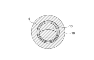
- FIG. 5 shows a cross section taken along line BB in FIG.
- the reel seat 9 according to an embodiment of the present invention has the cylindrical portion in a state in which the rod end side rod body 2a is inserted (and when the movable hood 13 is in the position shown in FIG. 2).
- a cross section perpendicular to the axial direction of the cylindrical portion 4 is viewed in a direction downward from the central axis of the cylindrical portion 4 (downward in the vertical direction of the paper of FIG. 5), the engaging portion 16 and the engaged portion 18b are viewed from the inside.
- a cylindrical portion 4, and a grip portion 23 are provided in this order, and a cross section perpendicular to the axial direction of the cylindrical portion 4 is viewed upward from the central axis of the cylindrical portion 4 (in the upper direction in the vertical direction of the paper of FIG. 5).
- the starting end portion of the inner protrusion 4a, the engaged portion 18b, the cylindrical portion 4, and the grip portion are provided in this order when viewed in the direction toward.
- the cylindrical portion 4 of the reel seat body 12 also has a circular or substantially circular outer surface, and a space capable of accommodating the engaging portion 16 formed by curving inside together with the cylindrical end portion 4b. is formed.
- the shape of the inside of the cylindrical part 4 can be variously considered depending on the shape of the constituent members such as the engaging part 16, and is not limited to a specific form.
- FIG. 6 shows a cross section taken along line CC in FIG.
- the reel seat 9 according to an embodiment of the present invention has the cylindrical portion in a state in which the rod end side rod body 2a is inserted (and when the movable hood 13 is in the position shown in FIG. 2).
- the reel seat 9 has the cylindrical portion in a state in which the rod end side rod body 2a is inserted (and when the movable hood 13 is in the position shown in FIG. 2).
- the section 18b, the cylindrical section 4, and the grip section 23 are provided in this order.
- the cylindrical portion 4 of the reel seat body 12 When viewed in the direction toward the cylindrical shaft 2, the rod end side rod body 2a, the inner protrusion 4a, the engaged portion 18b, the cylindrical portion 4, and the grip portion 23 are provided in this order.
- the cylindrical portion 4 of the reel seat body 12 also has a circular or substantially circular outer surface, and forms a space in which the rod end side rod body 2a can be accommodated.
- the internal shape of the cylindrical part 4 is formed into a cylindrical shape, and various shapes can be considered depending on the shapes of the constituent members such as the bottom side rod body 2a, the nut member 18, the spacer member 27, etc., and it is not limited to a specific form. do not have.
- FIG. 7 shows a cross section taken along line DD in FIG.
- the reel seat 9 according to an embodiment of the present invention has the cylindrical portion in a state in which the rod end side rod body 2a is inserted (and when the movable hood 13 is in the position shown in FIG. 2).
- the connecting portion 18c of the nut member 18, the cylindrical portion 4, and the grip portion 23 are provided in this order.
- the cylindrical portion 4 of the reel seat body 12 When viewed in the direction (upward in the vertical direction of the paper), the rod end side rod body 2a, the inner protrusion 4a, the spacer member 27, the connecting portion 18c of the nut member 18, the cylindrical portion 4, and the grip portion 23 are provided in this order. .
- the cylindrical portion 4 of the reel seat body 12 also has a circular or substantially circular outer surface, and forms a space in which the rod end side rod body 2a can be accommodated.
- the internal shape of the cylindrical part 4 is formed into a cylindrical shape, and various shapes can be considered depending on the shapes of the constituent members such as the bottom side rod body 2a, the nut member 18, the spacer member 27, etc., and it is not limited to a specific form. do not have.
- FIGS. 8(a) and 8(b) are perspective views (the former is viewed diagonally from above, and the latter is viewed diagonally from below).
- the movable hood 13 includes an engaging part 16 and a hood part 17, and when viewed in a cross section perpendicular to the axial direction of the cylindrical part 15 (the cross section shown in FIG. 4), the engaging part 16 is , arcuate or curved.
- the male threaded portion of the engaging portion 16 provided on the outer surface can be screwed into the female threaded portion formed on the engaged portion 18b on the inner surface of the nut member 18.
- the engaging portion 16 of the movable hood 13 is formed into an arc shape, and the angle of the arc is in the range of 70 degrees to 140 degrees.
- the engaging portion 16 and the hood portion 17 are arranged in the radial direction of the central axis of the reel seat 9.
- the hood portion 17 is formed inside the engaging portion 16 when viewed in the radial direction of the central axis of the reel seat 9.
- FIG. 9(a) shows a cross-sectional view of a reel sheet according to another embodiment of the present invention (a cross-sectional view in the vertical direction of the plane of FIG. 9(a) passing through the central axis of the reel sheet), and FIG. ) shows a front view of a reel seat according to another embodiment of the present invention.
- FIG. 9(c) shows a cross section taken along line EE in FIG. 9(a).
- the axial direction (front-back direction) and the up-down direction mean the direction shown in FIG. 9(a), and the left-right direction (side direction) means the direction perpendicular to the paper surface of FIG.
- the front means the tip side of the fishing rod
- the rear means the base end side
- the upper side means the reel side with respect to the axis X of the main rod (pole rod) when a double-bearing reel is installed
- the lower side means the means the opposite side.
- the axis X also corresponds to the axes of the reel seat 9, the reel seat main body 12, the reel leg mounting portion 12a, and the cylindrical portion 4, and these directions can be referred to as any one of these axial directions. .
- the reel seat body 12 includes a reel leg mounting surface 12a along the axial direction on which the reel leg 6a of the fishing reel 6 is mounted.
- the reel seat body 12 can be configured to have a length in the range of, for example, 150 mm to 200 mm, but is not limited thereto.
- this reel seat body 12 has the opposite side of the reel leg mounting surface 12a slightly bulged out, so that when the reel seat body 12 is gripped with the hand that is gripping it, it supports the ball of the foot or the vicinity thereof, so that it can be gripped easily.
- a bulging portion (trigger) 12b having an easily curved outer surface is formed. Note that the rod body may be connected to the front side of the reel seat body 12.
- the reel leg placement surface 12a of the reel seat body 12 is flat or substantially flat with a larger curvature than other circumferential portions (for example, the trigger 12b) adjacent to the reel leg placement surface 12a of the reel seat body 12. It is formed in a state extending in the axial direction of the reel seat main body 12 shown in FIG.
- a fixed hood 14 is integrally disposed at one end (on the rod tip side) of the reel seat body 12.
- One end of the reel leg mounting surface 12a of the reel seat body 12 is disposed inside the fixed hood 14.
- the reel seat main body 12 of the reel seat 9 includes a front cylindrical portion 15 at the front, the previously described cylindrical portion (rear cylindrical portion) 4 at the rear, and an outer surface of the cylindrical portion 4.
- the grip portion (rear grip) 23 that is gripped and held is fixed.
- the reel seat body 12 includes an intermediate connecting portion 24 that connects the front cylindrical portion 15 and the cylindrical portion (rear cylindrical portion) 4 in the axial direction, and these are integrally formed.
- the proximal end of the rod body 2 constituting the fishing rod is fixed to the inner surface of the front cylindrical portion 15 by adhesive or the like.
- the proximal end of the rod end side rod body 2a constituting the fishing rod is fixed to the inner surface of the protruding inner protrusion 4a by adhesive or the like, and the grip part 23 is fixed to the outer peripheral surface of the cylindrical part 4. , is configured to be flush with the surface of the cylindrical end portion 4b.
- a movable hood 13 is attached to the other end (rod base side) of the reel seat body 12 so as to be movable in the axial direction.
- the fishing reel 6 is mounted by placing the reel leg 6a on the reel leg mounting portion 12a, fitting the tip side into the fixed hood 14, and tightening the rear end side with the movable hood 13 that moves in the axial direction. is attached to and fixed to the reel seat 9.
- the reel seat 9 includes the reel seat main body 12 and the movable hood 13, but may include members other than these.
- the movable hood 13 includes an engaging portion 16 formed with a male thread, and a hood portion 17 curved inward in the radial direction and housing at least a portion of the reel leg 6a.
- the hood portion 17 is disposed so as to fit into an opening 8 formed below the rear end surface (near the cylindrical end portion 4b) of the intermediate connecting portion 24, and this opening 8 is arranged so as to fit into the opening 8 where the reel leg is placed. It is connected to section 12a. That is, when the movable hood 13 moves forward, the hood portion 17 fits into the rear end portion of the reel leg 6a placed on the reel leg placement portion 12a within the opening 8. .
- the male threaded portion of the engaging portion 16 of the movable hood 13 is threadedly engaged with the female threaded portion formed on the engaged portion 18b formed on the inner surface of the nut member 18 provided inside the cylindrical portion 4. It will be done like this. That is, by rotating the operating portion 18b of the nut member 18 in one direction, the movable hood 13 moves forward in the axial direction and tightens the rear end side of the reel leg 6a (reel attachment, fixed state), and the nut member 18 is rotated in one direction. By rotating the member 18 in the other direction, the movable hood 13 moves rearward in the axial direction and opens the rear end side of the reel leg 6a (reel removed state).
- the method of engaging the engaging portion 16 and the engaged portion 18b may be various conventionally known methods, and is not limited to a specific manner (screwing). Note that by providing a stopper member 20 on the rear end side of the operating portion 18a, it is possible to prevent the operating portion 18a from coming off to the rear side.
- the rod body 2 is provided on the inner surface of the nut member 18, and the pipe member 28 is provided on the outer surface of the nut member 18.
- a grip portion (rear grip) 23 is attached to the outer surface of this pipe member 28.
- the grip portion (rear grip) 23 may be attached to the outer surface of the pipe member 28 by threading, or may be attached using an adhesive.
- the aspects of the movable hood 13 and the nut member 18 are as described with reference to FIGS. 2 to 8, and are basically the same in this embodiment. Therefore, further details will be omitted.
- FIG. 9(c) shows a cross section taken along line EE in FIG. 9(a).
- the reel seat 9 according to an embodiment of the present invention is in a state where the rod end side rod body 2a is inserted (and when the movable hood 13 is in the position shown in FIG. 9(b)).
- a cross section perpendicular to the axial direction of the cylindrical end portion 4b is viewed in a direction downward from the central axis of the cylindrical end portion 4b (downward in the vertical direction of the paper in FIG. 9(c)), the rod body can be seen from the inside. 2.
- the engaged portion 18b, the engaging portion 16, and the cylindrical end portion 4b are provided in this order, and the cross section perpendicular to the axial direction of the cylindrical end portion 4b is arranged in the upward direction from the central axis of the cylindrical end portion 4b (
- the rod body 2, the engaged portion 18b, and the cylindrical end portion 4b are provided in this order when viewed in a direction (upward in the vertical direction of the paper of FIG. 9(c)).
- the shape of the inside of the cylindrical end portion 4b can be variously considered depending on the shape of the engaging portion 16, and is not limited to a specific form.
- a fishing rod 1 is configured to include one of the reel seats 9 described above and a rod body (the rod body 2 and the rod end side rod body 2).
- a rod butt side grip part 26 may be formed at the rod butt side end of the rod butt side rod body 2a, and in that case, the rod body is configured to include the rod butt side grip part 26. can do.
- the fishing rod even when a structure is adopted in which the position of the reel leg mounting portion of the reel seat is offset in a downward direction with respect to the axis of the main rod rod, when the reel is gripped, Equipped with a reel seat that can keep the reel fixed to the reel seat stably by preventing hands and fingers from touching the operating member for fixing the reel leg to the reel seat during casting and casting operations.
- a connecting portion 18c is interposed to provide a distance between the engaged portion 18b of the nut member 18 and the operating portion 18a, and the operating portion 18a is provided closer to the rod butt than the grip portion 23, which will be described later.
- the reel leg mounting section 12a and the operating section 18a can be formed at a sufficient distance from each other, so that hands and fingers do not touch the operating member for fixing the reel leg to the reel seat when gripping the reel or performing a casting operation. Since there is no such problem or the possibility thereof is significantly reduced, it becomes possible to maintain the fixed state of the reel 6 to the reel seat 9 for a long time.
- the reel seat body 12 can be formed of carbon fiber reinforced plastic (CFRP), glass reinforced plastic (GFRP), Al, or Mg.
- the reel sheet 12 may be made of GFRTP (continuous fiber), GFRTP (discontinuous fiber), CFRTP (continuous fiber), CFRTP (discontinuous fiber), or a hybrid.
- each component described herein is not limited to those explicitly described in the embodiments, and each component may be any number that may fall within the scope of the present invention. dimensions, materials, and arrangements. Further, components not explicitly described in this specification can be added to the described embodiments, or some of the components described in each embodiment can be omitted.
Landscapes
- Life Sciences & Earth Sciences (AREA)
- Environmental Sciences (AREA)
- Marine Sciences & Fisheries (AREA)
- Animal Husbandry (AREA)
- Biodiversity & Conservation Biology (AREA)
- Fishing Rods (AREA)
Priority Applications (2)
| Application Number | Priority Date | Filing Date | Title |
|---|---|---|---|
| CN202380063834.4A CN119816199A (zh) | 2022-09-06 | 2023-04-20 | 卷线器座及钓竿 |
| US18/873,897 US12501890B2 (en) | 2022-09-06 | 2023-04-20 | Reel seat and fishing rod |
Applications Claiming Priority (2)
| Application Number | Priority Date | Filing Date | Title |
|---|---|---|---|
| JP2022-141707 | 2022-09-06 | ||
| JP2022141707A JP7794715B2 (ja) | 2022-09-06 | 2022-09-06 | リールシート及び釣竿 |
Publications (1)
| Publication Number | Publication Date |
|---|---|
| WO2024053152A1 true WO2024053152A1 (ja) | 2024-03-14 |
Family
ID=90192231
Family Applications (1)
| Application Number | Title | Priority Date | Filing Date |
|---|---|---|---|
| PCT/JP2023/015742 Ceased WO2024053152A1 (ja) | 2022-09-06 | 2023-04-20 | リールシート及び釣竿 |
Country Status (4)
| Country | Link |
|---|---|
| US (1) | US12501890B2 (https=) |
| JP (1) | JP7794715B2 (https=) |
| CN (1) | CN119816199A (https=) |
| WO (1) | WO2024053152A1 (https=) |
Citations (5)
| Publication number | Priority date | Publication date | Assignee | Title |
|---|---|---|---|---|
| JPH0412861U (https=) * | 1990-05-22 | 1992-01-31 | ||
| JP2001028976A (ja) * | 1999-07-22 | 2001-02-06 | Ryobi Ltd | 釣 竿 |
| US20130283665A1 (en) * | 2012-04-05 | 2013-10-31 | Justin Poe | Seat for Spinning Reel |
| JP5517413B2 (ja) * | 2008-03-13 | 2014-06-11 | 株式会社シマノ | 釣り竿のリールシート及び釣り竿 |
| JP2022039168A (ja) * | 2020-08-28 | 2022-03-10 | グローブライド株式会社 | リールシート |
Family Cites Families (21)
| Publication number | Priority date | Publication date | Assignee | Title |
|---|---|---|---|---|
| US2543881A (en) * | 1948-10-11 | 1951-03-06 | Umphlette Charles Leonard | Floating reel seat for fishing rods |
| US3197908A (en) * | 1962-11-08 | 1965-08-03 | Walter F Hirsch | Reel seat for fishing rods |
| US3451156A (en) * | 1966-07-05 | 1969-06-24 | Conolon Corp | Fishing rod handle |
| US3616563A (en) * | 1970-01-27 | 1971-11-02 | Garcia Corp | Reel attachment |
| JPS4946557Y2 (https=) | 1971-11-22 | 1974-12-19 | ||
| US4222192A (en) * | 1978-12-26 | 1980-09-16 | Williams R. Harris, III | Handle and reel seat for a fishing rod |
| JPS60241833A (ja) * | 1984-05-14 | 1985-11-30 | 富士工業株式会社 | キヤステイングハンドル |
| JPS60241834A (ja) * | 1984-05-15 | 1985-11-30 | 富士工業株式会社 | 釣竿用リ−ルシ−ト |
| US5048223A (en) * | 1987-10-31 | 1991-09-17 | Daiwa Seiko, Inc. | Fishing rod |
| JPH02174624A (ja) | 1988-12-27 | 1990-07-06 | Aakisutoriaru:Kk | リール支持部材及び該部材とグリップとのアセンブリ |
| JP3252964B2 (ja) * | 1990-10-19 | 2002-02-04 | 株式会社シマノ | 釣り竿 |
| JP2717337B2 (ja) * | 1992-04-30 | 1998-02-18 | 富士工業株式会社 | 釣竿用リ−ルシ−ト |
| JP3169195B2 (ja) * | 1993-02-26 | 2001-05-21 | ダイワ精工株式会社 | 釣竿用キャスティングハンドル |
| JP3053767B2 (ja) * | 1996-05-16 | 2000-06-19 | 富士工業株式会社 | 釣竿用リールシート |
| JP3157124B2 (ja) * | 1997-06-20 | 2001-04-16 | 富士工業株式会社 | 釣竿用リールシート |
| US6067740A (en) * | 1998-12-17 | 2000-05-30 | Alley; F. William | Fishing rod reel seat assembly |
| US6393754B1 (en) * | 2000-09-21 | 2002-05-28 | F. William Alley | Reel seat assembly including reel foot holder having variable radius of curvature |
| JP4159404B2 (ja) * | 2003-05-16 | 2008-10-01 | 富士工業株式会社 | 釣竿用リールの取り付け構造及び釣竿用可動フード体 |
| US11457618B2 (en) * | 2018-12-15 | 2022-10-04 | Karl B. WEBBER | System and method for attaching fishing reel to fishing rod and selectively positioning the reel along the axis of the fishing rod |
| US20240023529A1 (en) * | 2022-07-22 | 2024-01-25 | Fuji Kogyo Co., Ltd. | Fishing rod handle and fishing rod including same |
| KR102662072B1 (ko) * | 2022-11-03 | 2024-04-30 | 후지코교 가부시기가이샤 | 릴 시트 및 이를 포함하는 낚싯대 |
-
2022
- 2022-09-06 JP JP2022141707A patent/JP7794715B2/ja active Active
-
2023
- 2023-04-20 US US18/873,897 patent/US12501890B2/en active Active
- 2023-04-20 CN CN202380063834.4A patent/CN119816199A/zh active Pending
- 2023-04-20 WO PCT/JP2023/015742 patent/WO2024053152A1/ja not_active Ceased
Patent Citations (5)
| Publication number | Priority date | Publication date | Assignee | Title |
|---|---|---|---|---|
| JPH0412861U (https=) * | 1990-05-22 | 1992-01-31 | ||
| JP2001028976A (ja) * | 1999-07-22 | 2001-02-06 | Ryobi Ltd | 釣 竿 |
| JP5517413B2 (ja) * | 2008-03-13 | 2014-06-11 | 株式会社シマノ | 釣り竿のリールシート及び釣り竿 |
| US20130283665A1 (en) * | 2012-04-05 | 2013-10-31 | Justin Poe | Seat for Spinning Reel |
| JP2022039168A (ja) * | 2020-08-28 | 2022-03-10 | グローブライド株式会社 | リールシート |
Also Published As
| Publication number | Publication date |
|---|---|
| CN119816199A (zh) | 2025-04-11 |
| JP2024037063A (ja) | 2024-03-18 |
| US12501890B2 (en) | 2025-12-23 |
| JP7794715B2 (ja) | 2026-01-06 |
| US20250359539A1 (en) | 2025-11-27 |
Similar Documents
| Publication | Publication Date | Title |
|---|---|---|
| JP7376449B2 (ja) | リールシート | |
| WO2023210053A1 (ja) | リールシート及び釣竿 | |
| WO2024053152A1 (ja) | リールシート及び釣竿 | |
| CN113558017B (zh) | 钓竿用卷线器座及钓竿 | |
| KR20220148111A (ko) | 릴 시트 | |
| JP7835653B2 (ja) | リールシート及び釣竿 | |
| JP2023160649A (ja) | リールシート及び釣竿 | |
| JP7656510B2 (ja) | リールシートグリップ部材、釣竿用ハンドル部材及び釣竿 | |
| CN118765876A (zh) | 钓竿 | |
| JP7798751B2 (ja) | リールシート及び釣竿 | |
| JP7661277B2 (ja) | グリップ構造及び釣竿 | |
| JP6898221B2 (ja) | 釣竿用リールシート及び釣竿 | |
| JP7743287B2 (ja) | リールシートグリップ部材、リールシートグリップ構造及び釣竿 | |
| AU2021438460B2 (en) | Fishing line guide and fishing rod equipped with said fishing line guide | |
| JP4148855B2 (ja) | 竿体の製造方法 | |
| JP7201567B2 (ja) | 魚釣用リール及びそのハンドル |
Legal Events
| Date | Code | Title | Description |
|---|---|---|---|
| 121 | Ep: the epo has been informed by wipo that ep was designated in this application |
Ref document number: 23862702 Country of ref document: EP Kind code of ref document: A1 |
|
| WWE | Wipo information: entry into national phase |
Ref document number: 18873897 Country of ref document: US |
|
| WWE | Wipo information: entry into national phase |
Ref document number: 202380063834.4 Country of ref document: CN |
|
| NENP | Non-entry into the national phase |
Ref country code: DE |
|
| WWP | Wipo information: published in national office |
Ref document number: 202380063834.4 Country of ref document: CN |
|
| 122 | Ep: pct application non-entry in european phase |
Ref document number: 23862702 Country of ref document: EP Kind code of ref document: A1 |
|
| WWP | Wipo information: published in national office |
Ref document number: 18873897 Country of ref document: US |