WO2024048695A1 - 複合半透膜及び複合半透膜の製造方法 - Google Patents
複合半透膜及び複合半透膜の製造方法 Download PDFInfo
- Publication number
- WO2024048695A1 WO2024048695A1 PCT/JP2023/031656 JP2023031656W WO2024048695A1 WO 2024048695 A1 WO2024048695 A1 WO 2024048695A1 JP 2023031656 W JP2023031656 W JP 2023031656W WO 2024048695 A1 WO2024048695 A1 WO 2024048695A1
- Authority
- WO
- WIPO (PCT)
- Prior art keywords
- composite semipermeable
- semipermeable membrane
- protrusion
- membrane
- microporous support
- Prior art date
- Legal status (The legal status is an assumption and is not a legal conclusion. Google has not performed a legal analysis and makes no representation as to the accuracy of the status listed.)
- Ceased
Links
Images


Classifications
-
- B—PERFORMING OPERATIONS; TRANSPORTING
- B01—PHYSICAL OR CHEMICAL PROCESSES OR APPARATUS IN GENERAL
- B01D—SEPARATION
- B01D69/00—Semi-permeable membranes for separation processes or apparatus characterised by their form, structure or properties; Manufacturing processes specially adapted therefor
- B01D69/12—Composite membranes; Ultra-thin membranes
-
- B—PERFORMING OPERATIONS; TRANSPORTING
- B01—PHYSICAL OR CHEMICAL PROCESSES OR APPARATUS IN GENERAL
- B01D—SEPARATION
- B01D71/00—Semi-permeable membranes for separation processes or apparatus characterised by the material; Manufacturing processes specially adapted therefor
- B01D71/06—Organic material
- B01D71/56—Polyamides, e.g. polyester-amides
Definitions
- the present invention relates to a composite semipermeable membrane useful for selective separation of liquid mixtures, and a method for manufacturing the same.
- membrane separation methods include microfiltration membranes, ultrafiltration membranes, nanofiltration membranes, and reverse osmosis membranes. It is used for the production of industrial ultrapure water, wastewater treatment, and recovery of valuable materials.
- the operation design is such that the chlorine added in pretreatment does not come into contact with the membrane, but due to an operational error, leaked chlorine comes into contact with the membrane, causing the membrane to oxidize. There is a risk of deterioration. Therefore, studies have been conducted to improve the chlorine resistance of these composite semipermeable membranes in order to reduce the risk of membrane deterioration due to chlorine leakage and extend the membrane life.
- Patent Document 3 As methods for improving chlorine resistance, a method of improving the monomer components forming the separation functional layer (Patent Document 3) and a method of forming a protective layer on the separation functional layer (Patent Document 4) are known.
- Patent Document 3 discloses a composite semipermeable membrane using sodium m-phenylenediamine-4-sulfonate as a polyfunctional amine forming a separation functional layer; A composite semipermeable membrane using a compound having hexafluoroalcohol as a side chain as a polyfunctional amine forming a separation functional layer has been disclosed.
- the composite semipermeable membranes described in Patent Documents 3 and 4 have chlorine resistance, membranes having both water permeability and removability have not been obtained. Therefore, an object of the present invention is to provide a composite semipermeable membrane having high water permeability and high removability even after contact with chlorine.
- the composite semipermeable membrane of the present invention has the following configuration.
- the separation functional layer has a plurality of protrusions made of a thin film containing crosslinked aromatic polyamide
- the average number density of protrusions having a height of 1/5 or more of the 10-point average surface roughness is 13.0 pieces/ ⁇ m or more, [1] to [4] above. ]
- the crosslinked aromatic polyamide includes a polyamide that is a polymer of trimesic acid chloride and m-phenylenediamine.
- the composite semipermeable membrane according to any one of [1] to [5] above.
- a method for manufacturing a composite semipermeable membrane comprising: [8] An element comprising the composite semipermeable membrane according to any one of [1] to [6] above.
- a fluid separation device comprising the composite semipermeable membrane according to any one of [1]
- a composite semipermeable membrane that has high water permeability and exhibits high removability even after contact with chlorine can be obtained.
- FIG. 1 is a cross-sectional view of a composite semipermeable membrane according to an embodiment of the present invention.
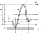
- FIG. 2 is a schematic diagram showing the structure of a protrusion made of a thin film in the separation functional layer.
- FIG. 3 is an enlarged view showing the structure of the protrusion.
- FIG. 4 is a schematic diagram showing the apparent height of the protrusion.
- ⁇ in the numerical range is a range that includes the numbers before and after it; for example, "0% by mass to 100% by mass” means a range of 0% by mass or more and 100% by mass or less. .
- FIG. 1 shows the structure of a composite semipermeable membrane 1 in this embodiment.
- the composite semipermeable membrane 1 according to the present embodiment includes a microporous support layer 3 and a separation functional layer 4 provided on the microporous support layer 3.
- the composite semipermeable membrane 1 may further include a base material 2.
- the "vertical” direction means the thickness direction of the composite semipermeable membrane, that is, the direction perpendicular to the membrane surface direction of the composite semipermeable membrane, and is the y-axis direction shown in FIGS. 1, 2, 3, and 4. Additionally, the separation functional layer is placed “on top” of the microporous support layer. In other words, the positive side of the y-axis is “up” and the negative side is “down.” Note that the x-axis direction shown in FIGS. 1, 2, 3, and 4 is the membrane surface direction of the composite semipermeable membrane.
- the microporous support layer 3 may be formed on the base material 2, and the composite semipermeable membrane 1 according to the embodiment of the present invention includes the base material 2 and the microporous support layer formed on the base material 2. It may have a support membrane including layer 3.
- the separation functional layer substantially has separation performance.
- the microporous support layer has substantially no ability to separate ions, etc., and can provide strength to the separation functional layer.
- the support membrane may include a base material and a microporous support layer, or the support membrane may not have a base material and may be composed only of the microporous support layer. good. That is, the microporous support layer may be a support membrane.
- the base material examples include fabrics made of polyester polymers, polyamide polymers, polyolefin polymers, and mixtures or copolymers thereof.
- a polyester polymer fabric with high mechanical and thermal stability is preferred.
- As the form of the fabric long fiber nonwoven fabrics, short fiber nonwoven fabrics, and even woven and knitted fabrics can be preferably used.
- the microporous support layer has a large number of pores that communicate from one side to the opposite side.
- the pore size or pore size distribution of the pores in the microporous support layer There are no particular limitations on the pore size or pore size distribution of the pores in the microporous support layer.
- the microporous support layer has pores with a symmetrical structure of uniform pore size, or has an asymmetric structure with pores that gradually increase in size from one side to the other, and the pores have a smaller pore size on the side. It is preferable to have pores having a structure in which the pore size on the surface is 0.1 to 100 nm.
- Materials for the microporous support layer include homopolymers such as polysulfone (hereinafter referred to as "PSf"), polyethersulfone, polyamide, polyester, cellulose polymer, vinyl polymer, polyphenylene sulfide, polyphenylene sulfide sulfone, polyphenylene sulfone, and polyphenylene oxide. or a copolymer, and these can be used alone or in a blend.
- Examples of the cellulose polymer include cellulose acetate and cellulose nitrate
- examples of the vinyl polymer include polyethylene, polypropylene, polyvinyl chloride, and polyacrylonitrile.
- homopolymers or copolymers such as PSf, polyamide, polyester, cellulose acetate, cellulose nitrate, polyvinyl chloride, polyacrylonitrile, polyphenylene sulfide, polyphenylene sulfide sulfone are preferable, and cellulose acetate, PSf , polyphenylene sulfide sulfone, and polyphenylene sulfone are more preferred, and PSf is particularly preferred because it has high chemical, mechanical, and thermal stability and is easy to mold.
- the weight average molecular weight (hereinafter referred to as "M w ”) of PSf is preferably 10,000 to 200,000, more preferably 15,000 to 100,000.
- M w weight average molecular weight
- the weight average molecular weight refers to a polystyrene equivalent value measured by gel permeation chromatography (GPC).
- the thickness of the base material and microporous support layer affects the strength of the composite semipermeable membrane and the packing density when it is used as an element. From the viewpoint of obtaining good mechanical strength and packing density, the total thickness of the base material and the microporous support layer is preferably 30 to 300 ⁇ m, more preferably 100 to 220 ⁇ m. Further, the thickness of the microporous support layer is preferably 20 to 100 ⁇ m. The thickness of the base material and the microporous support layer can be determined by calculating the average value of the thicknesses of 20 points measured at 20 ⁇ m intervals in the direction perpendicular to the thickness direction (in the plane direction of the membrane) during cross-sectional observation. Can be done.
- the separation functional layer in the composite semipermeable membrane of this embodiment is a layer responsible for the solute separation function, and contains crosslinked aromatic polyamide.
- the separation functional layer preferably contains crosslinked aromatic polyamide as a main component.
- “Mainly composed of crosslinked aromatic polyamide” means that the mass proportion of crosslinked aromatic polyamide in the separation functional layer is 50% by mass or more.
- the mass proportion of the crosslinked aromatic polyamide in the separation functional layer is preferably 80% by mass or more, more preferably 90% by mass or more, and the separation functional layer is substantially composed only of the crosslinked aromatic polyamide. It is more preferable that the When the separation functional layer is substantially composed only of crosslinked aromatic polyamide, it is intended that the mass proportion of the crosslinked aromatic polyamide in the separation functional layer is 99% by mass or more.
- the proportion of crosslinked aromatic polyamide in the separation functional layer of the composite semipermeable membrane can be calculated by nuclear magnetic resonance measurement (hereinafter referred to as "NMR measurement").
- NMR measurement nuclear magnetic resonance measurement
- the base material is physically peeled off from the composite semipermeable membrane, and the microporous support layer and separation functional layer are recovered.
- the recovered microporous support layer and separation functional layer were allowed to stand at 25°C for 24 hours, dried, and then added little by little into a beaker containing dichloromethane and stirred to dissolve the polymer constituting the microporous support layer. dissolve.
- the insoluble matter in the beaker is collected with a filter paper, the obtained insoluble matter is placed in a beaker containing dichloromethane and stirred, and the process of collecting the insoluble matter in the beaker is performed to form a microporous support layer in the dichloromethane solution. Repeat until the elution of the desired polymer is no longer detectable.
- the collected insoluble matter is dried in a vacuum dryer to remove remaining dichloromethane, and the obtained insoluble matter is isolated as a powder sample by freeze-pulverization.
- This powdered sample that is, the separation functional layer
- This powdered sample is immersed in a high-concentration and high-temperature sodium hydroxide aqueous solution until the solid content is dissolved, thereby alkaline hydrolyzing the separation functional layer, and 1 H of the obtained solution.
- NMR measurement It is possible to perform NMR measurement and quantify the monomer from the area of the obtained peak.
- the mass-based proportion of the monomer having an aromatic ring corresponds to the mass-based proportion of the crosslinked aromatic polyamide.
- crosslinked aromatic polyamide examples include aramid compounds, and the aramid compounds may also contain non-aromatic moieties in their molecular structure.
- crosslinked wholly aromatic polyamide is more preferable from the viewpoint of rigidity, chemical stability, and/or durability against operating pressure.
- a crosslinked aromatic polyamide can be formed by interfacial polycondensation of a polyfunctional aromatic amine and a polyfunctional aromatic acid halide.
- at least one of the polyfunctional aromatic amine and the polyfunctional aromatic acid halide contains a trifunctional or higher functional compound.
- a "polyfunctional aromatic amine” has two or more amino groups of at least one of a primary amino group and a secondary amino group in one molecule, and at least one of the amino groups is a secondary amino group. It means an aromatic amine which is a primary amino group.
- polyfunctional aromatic amines examples include o-phenylenediamine, m-phenylenediamine (hereinafter referred to as "m-PDA”), p-phenylenediamine, o-xylylenediamine, m-xylylenediamine, and p-xylylenediamine.
- o-diaminopyridine m-diaminopyridine, p-diaminopyridine, etc.
- a polyfunctional aromatic amine in which two amino groups are bonded to an aromatic ring in any of the ortho, meta, and para positions, 1 , 3,5-triaminobenzene, 1,2,4-triaminobenzene, 3,5-diaminobenzoic acid, 3-aminobenzylamine, 4-aminobenzylamine, and other polyfunctional aromatic amines.
- m-PDA p-phenylenediamine, or 1,3,5-triaminobenzene is preferably used from the viewpoint of improving the selective separation property, permeability, and heat resistance of the membrane.
- m-PDA it is more preferable to use m-PDA because of its ease of availability and handling.
- polyfunctional aromatic amines may be used alone or in combination of two or more.
- Polyfunctional aromatic acid halide means an aromatic acid halide having at least two halogenated carbonyl groups in one molecule.
- examples of trifunctional acid halides include trimesic acid chloride
- examples of difunctional acid halides include biphenyldicarboxylic acid dichloride, azobenzenedicarboxylic acid dichloride, terephthalic acid chloride, isophthalic acid chloride, naphthalenedicarboxylic acid chloride, etc.
- acid chlorides are preferred, particularly acid halides of 1,3,5-benzenetricarboxylic acid from the viewpoint of economy, ease of availability, ease of handling, and ease of reactivity.
- Trimesic acid chloride (hereinafter referred to as "TMC”) is preferred.
- the polyfunctional aromatic acid halide is preferably a polyfunctional aromatic acid chloride, and from the viewpoint of improving the selective separation property and heat resistance of the membrane, A polyfunctional aromatic acid chloride having 2 to 4 carbonyl chloride groups in one molecule is preferred.
- crosslinked aromatic polyamide is a polyamide that is a polymer of trimesic acid chloride and m-phenylenediamine.
- the separation functional layer in the composite semipermeable membrane of this embodiment is composed of a thin film.
- the above explanation regarding the composition of the separation functional layer also applies to thin films. That is, in the above description, "separation functional layer” may be read as "thin film”.
- FIG. 2 is a schematic diagram showing the structure of a protrusion made of a thin film in a cross section perpendicular to the membrane surface direction of a composite semipermeable membrane.
- FIG. 3 is a schematic diagram showing the structure of a protrusion made of a thin film in a cross section perpendicular to the membrane surface direction of a composite semipermeable membrane, and is a diagram showing the protrusion more enlarged than in FIG. 2.
- a protrusion is a structure formed by the thin film 5 of the separation functional layer, and is defined by two convex portions (also referred to as recesses) that are adjacent to each other in the x direction toward the microporous support layer 3 in the thin film 5. (Fig. 3).
- FIG. 3 shows an example in which one of both ends (vertex of the recess) of the protrusion (convex part 6) is separated from the surface of the microporous support layer 3, and the other is in contact with the surface. Note that both ends of the protrusion may be in contact with the microporous support layer 3, or both ends may be separated from the microporous support layer 3.
- the height of the surface of the microporous support layer 3 is 0% in the y-axis direction passing through the apex of the protrusion (protrusion 6), and the height of the protrusion (protrusion 6) is 0%.
- the apex is 100% of the height.
- the "apex of the protrusion" in the "apparent height of the protrusion” means the farthest position within the protrusion from the microporous support layer.
- An image of a cross section of the composite semipermeable membrane perpendicular to the membrane surface direction and having a length of 2.0 ⁇ m in the membrane surface direction is obtained by the following procedure.
- a sample section having a cross section perpendicular to the membrane surface direction of the composite semipermeable membrane can be obtained by a frozen ultrathin section method.
- cross-sectional observation can be performed using an electron microscope such as a scanning electron microscope (SEM, FE-SEM), a transmission electron microscope (TEM), or a scanning transmission electron microscope (STEM). The observation magnification is preferably 10,000 to 100,000 times.
- SEM scanning electron microscope
- TEM transmission electron microscope
- STEM scanning transmission electron microscope
- STEM scanning transmission electron microscope
- the surface of the thin film 5 in the separation functional layer appears as a curve.
- a roughness curve defined based on JIS B 0601 (ISO4287:1997) is determined.
- a cross-sectional image with a width of a reference length L (2.0 ⁇ m) is extracted from the cross section of the sample section in the direction of the average line A (hereinafter also referred to as "average line A") of the roughness curve.
- the "average line” is defined based on JIS B 0601 (ISO4287:1997), and is drawn so that the total area of the area surrounded by the average line and the roughness curve is equal above and below the average line in the measurement range. It is a straight line.
- the altitudes of the highest to fifth peaks on the roughness curve from the average line A (elevations of the highest to fifth peaks from the average line A, Yp1 to 5).
- the average absolute value of and the average absolute value of the elevations of the fifth valley bottom from the lowest valley bottom (elevations Yv1 to 5 of the fifth valley bottom from the lowest valley bottom from the average line A).
- this value expressed in nanometers (nm) is the 10-point average surface roughness in the cross-sectional image (FIG. 2).
- Similar measurements are performed on 10 randomly selected cross-sectional images, and the average value of the obtained 10-point average surface roughness is defined as the 10-point average surface roughness of the composite semipermeable membrane.
- the "height of the protrusion" can be calculated as follows. In a cross-sectional image with a width of 2.0 ⁇ m extracted from 10 cross-sectional images randomly selected as described above, the apparent height Pah of the protrusion is one-fifth or more of the 10-point average surface roughness described above. Regarding a certain protrusion, the distances d1 and d2 between both ends of the protrusion and the average line A in the membrane surface direction of the composite semipermeable membrane are measured. An average value d of distances d1 and d2 is calculated.
- the distances d1 and d2 are distances from the average line A to both ends of the protrusions in a direction perpendicular to the membrane surface direction of the composite semipermeable membrane. Further, both ends of the protrusion are the vertices of two adjacent parts of the thin film that are convex toward the microporous support layer. That is, both ends of the protrusion are the vertices of two recesses sandwiching the protrusion.
- the depth of both ends of the protrusion that is, the distance d1 from the average line A to the apex of the recess on the left side of the protrusion, and the distance from the average line A to the apex of the recess on the right side of the protrusion.
- the sum of the average d of d2 and the distance h from the average line A to the apex of the protrusion is calculated as the height Ph of the protrusion.
- the position where the distance from the average line A toward the microporous support layer is d is 0% of the height, and the apex of the protrusion is 100% of the height.
- the "vertex of the protrusion" in “height of the protrusion” means the position within the protrusion that is farthest from the average line of the roughness curve.
- the height of the protrusion is preferably 70 nm or more, more preferably 90 nm or more, from the viewpoint of ensuring sufficient water permeability of the composite semipermeable membrane. Further, from the viewpoint of suppressing deformation of the protrusions during high-pressure operation and obtaining stable film performance, the height of the protrusions is preferably 1000 nm or less, more preferably 800 nm or less, and even more preferably 400 nm or less. That is, the height of the protrusion is preferably 70 nm to 1000 nm.
- the height of the projections can be determined, for example, by the concentration of a polyfunctional aromatic amine in an aqueous solution of a polyfunctional aromatic amine, or the difference between a microporous support layer in contact with an aqueous solution of a polyfunctional aromatic amine and an organic solvent solution of a polyfunctional aromatic acid halide. It can be adjusted by changing the temperature of contact.
- Thickness of a thin film means the shortest distance from a point on the surface of the thin film to the opposite surface.
- the thickness of the thin film can be measured by photographing a cross section of the protrusion perpendicular to the membrane surface direction of the composite semipermeable membrane using a transmission electron microscope (TEM), and importing the cross-sectional photograph into image analysis software for analysis.
- the observation magnification may be appropriately determined depending on the thickness of the thin film. For example, if the thickness of the thin film is approximately 10 to 100 nm, the observation magnification may be set to 50,000 to 100,000 times so that the cross-sectional shape of the thin film can be observed and the measurement is not localized.
- the protrusions to be measured for the thin film thickness are randomly selected from protrusions having a height of one-fifth or more of the 10-point average surface roughness.
- the thickness of the thin film constituting the protrusion, and the ratio of the average thickness T98 of the thin film in the range of 75 to 98% of the height of the protrusion to the average thickness T25 of the thin film in the range of 2 to 25% of the height of the protrusion (T98/T25 ) can be calculated as follows.
- the range of 75 to 98% of the height of the protrusion is also referred to as the "upper part of the protrusion", and the range of 2 to 25% of the height of the protrusion is also referred to as the "lower part of the protrusion”.
- the average value d of the depths d1 and d2 of the recesses on both sides of the protrusion (protrusion 6) in the x-axis direction is calculated.
- position Z at a distance of d from the average line A has a height of 0%
- position B of the apex of the protrusion has a height of 100%. %.
- the thickness of the thin film constituting the protrusion is measured at 10 random locations on each of the upper and lower parts of the protrusion. Similar measurements are performed on five protrusions whose height is one-fifth or more of the 10-point average surface roughness.
- the arithmetic mean value is calculated for the 50 points of the thin film thickness at the lower part of the protrusion. This value is defined as the average thickness T25 of the lower part of the protrusion formed by the thin film in the composite semipermeable membrane.
- the arithmetic mean of the thickness of the thin film in the area above the protrusion is similarly calculated, and this is set as the average thickness T98 of the upper part of the protrusion constituted by the thin film.
- the average thickness T25 of the lower part of the protrusion is set to 13 to 13. Preferably, it is 24 nm.
- the thickness of the thin film constituting the protrusions is determined by the temperature and heating temperature at which the microporous support layer in which the polyfunctional aromatic amine aqueous solution is brought into contact with the organic solvent solution of the polyfunctional aromatic acid halide, and the crosslinked aromatic polyamide described below. It can be adjusted by a step of bringing a solution containing a compound containing an amide group into contact with the layer containing the amide group.
- the ratio (T98/T25) of the average thickness T98 of the upper part of the protrusion to the average thickness T25 of the lower part of the protrusion is preferably 0.95 or less, and more preferably 0.70 to 0.92.
- Composite semipermeable membranes are generally used in layers, with a channel material inserted between the membranes. When T98/T25 satisfies this range, the thin film is thin and flexible at the top of the protrusion, and thick and strong at the bottom of the protrusion, so even if the protrusion rubs against the channel material or other composite semipermeable membrane during use, The force is distributed under the protrusion, reducing damage and maintaining the salt removal rate.
- the separation functional layer may contain amide groups derived from the polymerization of polyfunctional aromatic amines and polyfunctional aromatic acid halides, and amino groups and carboxy groups derived from unreacted functional groups.
- the ratio of oxygen atoms to nitrogen atoms (O/N ratio) in the protrusion is obtained by analyzing using electron energy-loss spectroscopy (EELS) during TEM observation.
- EELS electron energy-loss spectroscopy
- the present inventors investigated the O/N ratio in the range of 2 to 25% of the apparent height of the protrusion for protrusions whose apparent height Pah is one-fifth or more of the above-mentioned 10-point average surface roughness.
- a composite semipermeable membrane that satisfies y/x ⁇ 1.3 has particularly high water permeability. It has been found that it has removability and also shows high removability even after contact with chlorine.
- x and y are monomer concentrations such as polyfunctional aromatic amines and polyfunctional aromatic acid halides, additives that may be used in interfacial polycondensation, and compounds containing amide groups in the layer containing the crosslinked aromatic polyamide described below. This can be adjusted by introducing a step of contacting a solution containing .
- the O/N ratio in the main skeleton repeating unit of the crosslinked aromatic polyamide is the same both above and below the protrusion, the O/N ratio at the protrusion is substantially (crosslinked aromatic It is proportional to (the carboxy group present at the end of the polyamide)/(the amino group present at the end of the crosslinked aromatic polyamide).
- the terminal functional groups also affect the removal performance and water permeability of the composite semipermeable membrane. In a region where the density of amino groups is high, the separation functional layer has a sparse structure and has low resistance to water permeation, increasing water permeability, but the solute removal performance is insufficient.
- the separation functional layer has a dense structure and has a high water permeation resistance, so the water permeability is low, but the solute removal performance is improved.
- the O/N ratio gradient structure refers to a structure in which the O/N ratio is different between the upper part and the lower part of the protrusion, and the O/N ratio is higher on the upper part of the protrusion than on the lower part. .
- the protrusions contain sufficient carboxyl groups in the range of 75 to 98% of the apparent height of the protrusions that are most easily accessible to raw water, so that the electrostatic field formed by charges It is preferable that y ⁇ 0.90 be satisfied, and it is more preferable that y ⁇ 1.2 be satisfied from the viewpoint of expected improvement in salt removability due to the hydrophilicity of the carboxy group and improvement in water permeability due to the hydrophilicity of the carboxy group.
- y ⁇ 2.0 from the viewpoint of suppressing clogging of pores constituted by the crosslinked aromatic polyamide due to strong hydrogen bonds between the molecules of the crosslinked aromatic polyamide or between carboxyl groups within the molecule, it is preferable that y ⁇ 2.0. That is, 0.90 ⁇ y ⁇ 2.0 is preferable.
- x which is the average value of the O/N ratio in the range of 2 to 25% of the apparent height of the protrusion
- y which is the average value of the O/N ratio in the range of 75 to 98% of the apparent height of the protrusion
- the protrusions preferably satisfy x ⁇ 0.50 from the viewpoint of achieving both water permeability and removal performance by appropriate amino group density. Furthermore, although the contribution is small compared to the 75% to 98% portion of the apparent height of the protrusion, by satisfying x ⁇ 0.50, oxidative deterioration that occurs when the oxidizing agent reaches the root of the protrusion can also be suppressed. On the other hand, from the viewpoint of suppressing clogging of pores constituted by the crosslinked aromatic polyamide due to strong hydrogen bonds between the molecules of the crosslinked aromatic polyamide or between carboxyl groups within the molecule, it is preferable that x ⁇ 2.0. That is, 0.50 ⁇ x ⁇ 2.0 is preferable.
- the average number density of the protrusions in the composite semipermeable membrane according to this embodiment is 13.0% from the viewpoint of obtaining sufficient water permeability and from the viewpoint of suppressing the deformation of the protrusions during pressurization and obtaining stable performance. It is preferably 0 pieces/ ⁇ m or more, and more preferably 15.0 pieces/ ⁇ m or more. Further, from the viewpoint that the growth of the protrusions sufficiently progresses and it is easy to obtain a composite semipermeable membrane having the desired water permeability, the above-mentioned average number density of the protrusions is preferably 50.0 pieces/ ⁇ m or less, and 40.0 ⁇ m or less. More preferably, the number is 0 pieces/ ⁇ m or less.
- the average number density of protrusions is preferably 13.0 pieces/ ⁇ m to 50.0 pieces/ ⁇ m.
- the average number density of the protrusions described above can be adjusted by changing the material of the microporous support layer, changing the concentration of the material used for the microporous support layer, for example, changing the PSf concentration, and the time and temperature of interfacial polycondensation.
- the average number density of protrusions is determined by the 10-point average surface roughness in a cross-sectional image whose length in the membrane surface direction is 2.0 ⁇ m extracted from a cross-sectional image perpendicular to the membrane surface direction of a composite semipermeable membrane selected at random.
- the separation functional layer is preferably placed on the surface side of the composite semipermeable membrane, and is preferably placed on the primary filtration side. More preferred.
- Method for manufacturing a composite semipermeable membrane is not particularly limited as long as a composite semipermeable membrane satisfying the desired characteristics described above can be obtained, but for example, it can be manufactured by the following method. Can be done.
- a method for manufacturing a composite semipermeable membrane having a microporous support layer and a separation functional layer provided on the microporous support layer includes: forming a layer containing a crosslinked aromatic polyamide on the microporous support layer by interfacial polycondensation using an aqueous polyfunctional aromatic amine solution and an organic solvent solution of a polyfunctional aromatic acid halide; contacting the layer containing the crosslinked aromatic polyamide with a solution containing a compound containing an amide group; Equipped with
- PSf is dissolved in a good solvent for PSf to prepare a microporous support layer stock solution.
- a good solvent for PSf for example, N,N-dimethylformamide (hereinafter referred to as "DMF") is preferable.
- the concentration of PSf in the microporous support layer stock solution is preferably 12 to 25% by mass, more preferably 14 to 23% by mass.
- the higher the polymer concentration (i.e., solid content concentration) in the polymer solution the higher the number density of particles on the surface of the microporous support layer, which results in a microporous support layer with a higher number density of protrusions on the separation functional layer.
- the water permeability also increases.
- the surface pore diameter of the microporous support layer can be adjusted, and the appropriate height and/or height can be adjusted during the formation of the separation functional layer.
- a protrusion with an apparent height is formed.
- concentration of PSf in the stock solution of the microporous support layer within this range, it is possible to achieve both strength and permeability of the resulting microporous support layer.
- concentration of the material in the stock solution of the microporous support layer can be adjusted as appropriate depending on the material used, the good solvent, and the like.
- the obtained microporous support layer stock solution is applied to the surface of the substrate and immersed in a coagulation bath containing a non-solvent of PSf.
- a non-solvent for PSf contained in the coagulation bath for example, water is preferable.
- the coagulation bath may be composed only of a non-solvent for PSf, or may contain a good solvent for PSf to the extent that the stock solution of the microporous support layer can be coagulated.
- the solvent remaining in the membrane may be removed by washing the obtained support membrane before forming the separation functional layer.
- a polyfunctional aromatic amine and a polyfunctional aromatic acid chloride are mixed on the support film obtained in "(2-1) Formation of support film".
- the method of polymerization and solidification will be described as an example.
- interfacial polycondensation method is most preferred from the viewpoint of productivity and performance. The interfacial polycondensation process will be explained below.
- the step of interfacial polycondensation includes (a) a step of bringing an aqueous solution containing a polyfunctional aromatic amine into contact with a support membrane, and (b) a step of bringing an organic solvent solution containing a polyfunctional aromatic acid chloride into contact with a polyfunctional aromatic amine. (c) draining the organic solvent solution after contact; and (d) separating the separation functional layer produced by interfacial polycondensation from the amide group. It is preferable to include the steps of: (e) cleaning the composite semipermeable membrane with hot water; and (e) cleaning the composite semipermeable membrane with hot water.
- the microporous support layer As the microporous support layer, the polyfunctional aromatic amine, and the polyfunctional aromatic acid halide, those mentioned above can be mentioned, and preferred ones are also the same.
- the concentration of the polyfunctional aromatic amine in the aqueous polyfunctional aromatic amine solution is preferably in the range of 0.1 to 20% by mass, and preferably in the range of 0.5 to 15% by mass. More preferred. When the concentration of the polyfunctional aromatic amine is within this range, the manufactured composite semipermeable membrane can have sufficient solute removal performance and water permeability. Note that two or more types of polyfunctional aromatic amines may be used.
- the polyfunctional aromatic amine aqueous solution does not contain surfactants, organic solvents, alkaline compounds, antioxidants, etc. as long as they do not interfere with the reaction between the polyfunctional aromatic amine and the polyfunctional aromatic acid halide. You can leave it there.
- the surfactant has the effect of improving the wettability of the support membrane surface and reducing the interfacial tension between the polyfunctional aromatic amine aqueous solution and the nonpolar solvent.
- the organic solvent may act as a catalyst for the interfacial polycondensation reaction, and by adding the organic solvent, the interfacial polycondensation reaction may be carried out efficiently.
- the polyfunctional aromatic amine aqueous solution is preferably brought into contact with the support membrane uniformly and continuously.
- a method of coating a polyfunctional aromatic amine aqueous solution on the support membrane or a method of immersing the support membrane in a polyfunctional aromatic amine aqueous solution can be mentioned.
- the contact time between the support membrane and the polyfunctional aromatic amine aqueous solution is preferably 1 second to 10 minutes, more preferably 3 seconds to 3 minutes.
- the support membrane after contact with the polyfunctional aromatic amine aqueous solution is held vertically and the excess aqueous solution is naturally drained.
- Examples include a method of letting the liquid flow down, or a method of forcibly draining the liquid by blowing an air stream of nitrogen or the like from an air nozzle. Further, after draining, the membrane surface can be dried to partially remove water from the polyfunctional aromatic amine aqueous solution.
- the polyfunctional aromatic acid chloride includes, for example, TMC, biphenyldicarboxylic acid dichloride, azobenzenedicarboxylic acid dichloride, terephthalic acid chloride, isophthalic acid chloride, naphthalenedicarboxylic acid chloride, 2,5-furandicarboxylic acid chloride. etc. These polyfunctional aromatic acid chlorides may be used alone or in combination of two or more.
- the organic solvent must be immiscible with water, dissolve the polyfunctional aromatic acid chloride, do not attack the support membrane, and be inert to the polyfunctional aromatic amine and the polyfunctional aromatic acid chloride. is preferred.
- the organic solvent include hydrocarbon compounds such as n-nonane, n-decane, n-undecane, n-dodecane, isooctane, isodecane, and isododecane, and mixed solvents thereof.
- the concentration of polyfunctional aromatic acid chloride in the organic solvent solution is preferably 0.01 to 10% by mass, more preferably 0.02 to 4% by mass, and more preferably 0.03 to 2% by mass. It is even more preferable that there be.
- concentration of the polyfunctional aromatic acid chloride is 0.01% by mass or more, polymerization can proceed at a sufficient reaction rate.
- concentration of the polyfunctional aromatic acid chloride is 10% by mass or less, the occurrence of side reactions during polymerization can be suppressed.
- the organic solvent solution may contain a compound such as a surfactant, if necessary, as long as it does not inhibit polymerization.
- the method of contacting the organic solvent solution of polyfunctional aromatic acid chloride with the support membrane that has been brought into contact with the polyfunctional aromatic amine aqueous solution is the same as the method of contacting the polyfunctional aromatic amine aqueous solution with the support membrane in step (a). You can do the same.
- a separation functional layer begins to be formed by bringing the polyfunctional aromatic acid chloride solution into contact with the support membrane that has been brought into contact with the polyfunctional aromatic amine aqueous solution.
- the temperature at which the microporous support layer brought into contact with the aqueous solution containing the polyfunctional aromatic amine and the solution in which the polyfunctional aromatic acid halide is dissolved is preferably 25 to 60°C, and preferably 30 to 55°C. °C is more preferable.
- the temperature By setting the temperature to 25° C. or higher, the height and/or apparent height of the protrusion becomes sufficient. Further, by setting the temperature to 60° C. or lower, the reaction rate becomes appropriate, the increase in the thickness of the thin film and the progress of coalescence of protrusions are suppressed, and sufficient water permeability is easily obtained in the manufactured composite semipermeable membrane. In addition, the amount of amine initially supplied from the support film to the interfacial polycondensation site becomes appropriate, suppressing the amount of amino groups in the range of 2 to 25% of the apparent height of the protrusions, and making it easier to satisfy x ⁇ 0.50. .
- the contact temperature is 25 to 60°C
- the number of protrusions increases and the surface area of the reaction interface increases, which increases the amount of polyamide and suppresses the increase in the average thicknesses T25 and T98 of the protrusions.
- the support film may be heated, or a heated solution of a polyfunctional aromatic acid halide in an organic solvent may be brought into contact with the support film.
- the temperature of the membrane surface immediately after the polyfunctional aromatic amine aqueous solution and the polyfunctional aromatic acid halide solution are brought into contact can be measured with a non-contact thermometer such as a radiation thermometer.
- the separation functional layer and the support membrane may be heat-treated.
- the heating temperature is preferably 50 to 180°C, more preferably 60 to 160°C, even more preferably 80 to 150°C.
- step (c) the organic solvent is removed from the support membrane and the separation functional layer by draining the organic solvent solution after the reaction.
- the organic solvent can be removed, for example, by holding the membrane vertically and removing the excess organic solvent by gravity, by blowing air with a blower to dry and remove the organic solvent, or by using a mixed fluid of water and air. A method of removing excess organic solvent can be used.
- step (d) the functional layer produced by interfacial polycondensation is brought into contact with solution A containing a compound containing an amide group.
- the compound containing an amide group include a chain amide compound, a cyclic amide compound, and the like.
- chain amide compounds include N-methylformamide, N,N-dimethylformamide, N,N-dimethylacetamide, N,N-diethylformamide, N,N-diisopropylformamide, N,N-dibutylformamide, N, Examples include N-diethylacetamide, tetramethylurea, tetraethylurea, N,N-diethyldodecanamide and the like.
- cyclic amide compound examples include N-methylpyrrolidinone, ⁇ -butyrolactam, ⁇ -caprolactam, 1,3-dimethyl-2-imidazolidinone, N,N'-dimethylpropylene urea, and the like.
- the separation functional layer contains a polyamide having a polyfunctional aromatic acid chloride end, a carboxy end obtained by hydrolyzing the acid chloride end, a polyamide having a polyfunctional aromatic amino group end, an oligomer, and an unreacted monomer. ing.
- solution A containing a compound containing an amide group By contacting solution A containing a compound containing an amide group, the amide group of solution A and the amino group present in the separation functional layer interact through hydrogen bonding, and oligomers and unreacted monomers having amino groups are separated. Since nitrogen atoms (N) are easily removed from the functional layer, the number of nitrogen atoms (N) contained in the separation functional layer decreases.
- the compound having an amide group acts on the acid chloride terminal and promotes hydrolysis, the amount of carboxy groups contained in the separation functional layer increases, and the number of oxygen atoms (O) also increases.
- the portions in the separation functional layer where the apparent height of the protrusions ranges from 75% to 98% have less steric hindrance than the portions where the apparent height ranges from 2% to 25%, so compounds having an amide group can easily approach them, resulting in the above effects. Great effect. Therefore, for the protrusions in the separation functional layer, y, which is the average value of the O/N ratio in the range of 75% to 98% of the apparent height of the protrusions, becomes large and satisfies y ⁇ 0.90 and y/x ⁇ 1.3.
- the hydrolysis of the acid chloride terminal is promoted and the amino group-containing oligomer and unreacted monomer are removed, so that the polymerization reaction in the protrusion height range of 75 to 98% can be carried out at a protrusion height of 2 to 25%. Since the termination reaction proceeds faster than the polymerization reaction in the % range, it becomes easier to satisfy T98/T25 of 0.95 or less.
- the concentration of the compound containing an amide group in solution A is preferably 0.1 to 40% by mass, more preferably 1.0 to 30% by mass. When the concentration is 0.1% by mass or more, the above effects can be sufficiently obtained. In addition, since the concentration is 40% by mass or less, even if the compound containing an amide group is a good solvent for PSf that forms the support membrane, it will not attack the separation functional layer or the support membrane and suppress a decrease in removal rate. can.
- the time for which the separation functional layer is brought into contact with solution A is preferably within 5 minutes, more preferably within 2 minutes. By keeping the contact time within 5 minutes, the effect on the portion of the protrusion with an apparent height of 2 to 25% is suppressed, making it easier to satisfy y/x ⁇ 1.3.
- the temperature of solution A to be brought into contact is preferably 0 to 50°C, more preferably 5 to 40°C.
- the contacting method include a method of coating the surface of the composite semipermeable membrane with solution A, and a method of immersing the composite semipermeable membrane in solution A.
- step (e) the composite semipermeable membrane is washed with hot water.
- the temperature of the hot water is preferably 40 to 95°C, more preferably 60 to 95°C.
- the temperature of the hot water is 40° C. or higher, unreacted substances and oligomers remaining in the membrane can be sufficiently removed.
- the temperature of the hot water is 95° C. or lower, the degree of shrinkage of the composite semipermeable membrane does not become large, and good permeation performance can be maintained.
- the preferable temperature range of the hot water can be adjusted as appropriate depending on the polyfunctional aromatic amine or polyfunctional aromatic acid chloride used.
- the performance of the composite semipermeable membrane can be improved by introducing a new functional group through a modification treatment using an appropriately selected chemical reaction on the amino groups present in the crosslinked aromatic polyamide.
- new functional groups include alkyl groups, alkenyl groups, alkynyl groups, halogeno groups, hydroxyl groups, ether groups, thioether groups, ester groups, aldehyde groups, nitro groups, nitroso groups, nitrile groups, and azo groups. .
- Composite semi-permeable membranes are made of feed water channel material such as plastic net, permeate water channel material such as tricot, and if necessary, a film to increase pressure resistance, as well as a large number of holes.
- the membrane element is wound around a cylindrical water collecting pipe, and is suitably used as a spiral-type composite semipermeable membrane element.
- a composite semipermeable membrane module can be obtained in which these elements are connected in series or in parallel and housed in a pressure vessel.
- the above-described composite semipermeable membrane, its elements, and modules can be combined with a pump that supplies water to them, a device that pre-treats the water, and the like to configure a fluid separation device.
- a separation device By using this separation device, it is possible to separate feed water into permeated water such as drinking water and concentrated water that has not passed through the membrane, thereby obtaining water suitable for the purpose.
- the feed water to be treated by the composite semipermeable membrane is a liquid mixture containing total dissolved solids (hereinafter referred to as "TDS") of 500 mg/L or more and 100 g/L or less, such as seawater, brine, and waste water.
- TDS refers to the total amount of dissolved solids, and is expressed as "mass divided by volume (mass divided by volume)" or "mass ratio.” According to the definition, it can be calculated from the weight of the residue obtained by evaporating a solution filtered through a 0.45 ⁇ m filter at a temperature between 39.5°C and 40.5°C, but more simply, it can be calculated from the practical salinity (S). converted.
- the higher the solute removal performance of the membrane the better the water quality can be ensured even if the operating pressure is lowered.
- the initial salt removal rate before contact with chlorine is preferably 99.75% or more.
- the salt permeability ratio (SP ratio) before and after the chlorine resistance test described in the example is 2.00 or less.
- the solute removal rate decreases, but as the temperature decreases, the membrane permeation flux also decreases, so it is preferably 5 to 45°C or less.
- scales such as magnesium may occur in feed water with a high solute concentration such as seawater, and there is a concern that membrane deterioration due to high pH operation may occur. Driving in the area is preferred.
- SP ratio (100-salt removal rate after immersion)/(100-salt removal rate before immersion) ⁇ ...Equation (2) Normally, the salt removal rate of composite semipermeable membranes decreases when immersed in chlorine. As the SP ratio becomes larger than 1.00, it means that the salt removal rate of the composite semipermeable membrane decreases due to chlorine immersion.
- Example 1 The support membrane obtained in Reference Example 1 was immersed in a 3.0% by mass aqueous m-phenylenediamine solution for 2 minutes. The support membrane was slowly pulled up vertically and nitrogen was blown from an air nozzle to remove excess aqueous solution from the surface of the support membrane. In an environment controlled at 40°C, a 40°C n-decane solution containing 0.16% by mass of TMC was applied so that the surface of the support membrane was completely wetted. Next, the supporting membrane was heated in an oven at 120°C, and then, in order to remove excess solution from the membrane, the membrane was placed vertically to drain the liquid, and then dried by blowing air at 20°C using a blower. Ta.
- the dried membrane was immersed for 2 minutes at 25° C. in a 10% by mass aqueous solution of N,N-dimethylformamide as a compound containing an amide group. Thereafter, the composite semipermeable membrane of Example 1 was obtained by washing the membrane with 90°C pure water. The height of the protrusions of the composite semipermeable membrane of Example 1 was 102 nm.
- Example 2 was prepared in the same manner as in Example 1, except that the oven temperature was set to 150°C, and after drying by blowing air, it was immersed in a 30.0 mass% N,N-dimethylformamide aqueous solution at 5°C for 2 minutes. A composite semipermeable membrane was obtained.
- Example 3 A composite semipermeable membrane of Example 3 was obtained in the same manner as in Example 1, except that after drying by blowing air, it was immersed in a 10.0 mass % N,N-dimethylformamide aqueous solution at 10° C. for 2 minutes.
- Example 4 A composite semipermeable membrane of Example 4 was obtained in the same manner as in Example 1, except that the temperature of the N,N-dimethylformamide aqueous solution brought into contact was 45°C.
- Example 5 A composite semipermeable membrane of Example 5 was obtained in the same manner as in Example 1 except that the m-phenylenediamine aqueous solution was changed to 6.0% by mass.
- Example 6 A composite semipermeable membrane of Example 6 was obtained in the same manner as in Example 2, except that the concentration of the N,N-dimethylformamide aqueous solution brought into contact was 1.0% by mass.
- Example 7 A composite semipermeable membrane of Example 7 was obtained in the same manner as in Example 1, except that the solution containing the compound containing an amide group to be contacted was changed to ⁇ -caprolactam to obtain a 10.0% by mass ⁇ -caprolactam aqueous solution. .
- Example 8 A composite semipermeable membrane of Example 8 was obtained in the same manner as in Example 2, except that the temperature of the n-decane solution of TMC to be applied was 65°C.
- Example 9 The procedure was carried out in the same manner as in Example 1, except that a 40°C n-decane solution containing 0.16% by mass TMC and 0.016% by mass isophthalic acid chloride was used as the polyfunctional aromatic acid halide solution. A composite semipermeable membrane of Example 9 was obtained.
- Comparative example 1 A composite semipermeable membrane of Comparative Example 1 was obtained in the same manner as in Example 5, except that the step of bringing the dried membrane into contact with a solution containing a compound containing an amide group was not performed.
- Comparative example 2 After applying a 40°C n-decane solution containing 0.16% by weight of TMC so that the surface of the support membrane was completely wet, an n-decane solution containing 0.32% by weight of TMC was further applied to the support membrane, and then 120% A composite semipermeable membrane of Comparative Example 2 was obtained in the same manner as Comparative Example 1 except that it was heated in an oven at .degree.
- Comparative Example 3 Comparative Example 3 was carried out in the same manner as Comparative Example 1, except that the solvent for the TMC solution was isooctane, the solution temperature was 25°C, the coating was carried out in an environment controlled at 25°C, and the oven temperature was 150°C. A composite semipermeable membrane was obtained.
- Comparative example 4 The composite half of Comparative Example 4 was prepared in the same manner as Comparative Example 1, except that the step of placing it in an oven at 120°C was omitted, the temperature of the TMC n-decane solution was 25°C, and the coating was performed in an environment controlled at 25°C. A permeable membrane was obtained.
- Comparative example 5 A composite semipermeable membrane of Comparative Example 5 was obtained in the same manner as Comparative Example 1, except that after drying by blowing air, it was immersed in a 1% by mass tributyl phosphate aqueous solution at 25° C. for 2 minutes.
- Comparative example 6 A composite semipermeable membrane of Comparative Example 6 was obtained in the same manner as Comparative Example 1, except that after drying by blowing air, it was immersed in a 10% by mass isopropyl alcohol aqueous solution at 25° C. for 2 minutes.
Landscapes
- Chemical & Material Sciences (AREA)
- Chemical Kinetics & Catalysis (AREA)
- Separation Using Semi-Permeable Membranes (AREA)
Priority Applications (1)
| Application Number | Priority Date | Filing Date | Title |
|---|---|---|---|
| JP2023557452A JPWO2024048695A1 (https=) | 2022-08-31 | 2023-08-30 |
Applications Claiming Priority (2)
| Application Number | Priority Date | Filing Date | Title |
|---|---|---|---|
| JP2022-137501 | 2022-08-31 | ||
| JP2022137501 | 2022-08-31 |
Publications (1)
| Publication Number | Publication Date |
|---|---|
| WO2024048695A1 true WO2024048695A1 (ja) | 2024-03-07 |
Family
ID=90099717
Family Applications (1)
| Application Number | Title | Priority Date | Filing Date |
|---|---|---|---|
| PCT/JP2023/031656 Ceased WO2024048695A1 (ja) | 2022-08-31 | 2023-08-30 | 複合半透膜及び複合半透膜の製造方法 |
Country Status (2)
| Country | Link |
|---|---|
| JP (1) | JPWO2024048695A1 (https=) |
| WO (1) | WO2024048695A1 (https=) |
Citations (3)
| Publication number | Priority date | Publication date | Assignee | Title |
|---|---|---|---|---|
| JPS6312310A (ja) * | 1986-07-04 | 1988-01-19 | Toray Ind Inc | 半透性複合膜の製造方法 |
| JP2016144794A (ja) * | 2015-01-29 | 2016-08-12 | 東レ株式会社 | 複合半透膜および複合半透膜エレメント |
| WO2018003943A1 (ja) * | 2016-06-29 | 2018-01-04 | 東レ株式会社 | 複合半透膜及び複合半透膜の製造方法 |
-
2023
- 2023-08-30 JP JP2023557452A patent/JPWO2024048695A1/ja active Pending
- 2023-08-30 WO PCT/JP2023/031656 patent/WO2024048695A1/ja not_active Ceased
Patent Citations (3)
| Publication number | Priority date | Publication date | Assignee | Title |
|---|---|---|---|---|
| JPS6312310A (ja) * | 1986-07-04 | 1988-01-19 | Toray Ind Inc | 半透性複合膜の製造方法 |
| JP2016144794A (ja) * | 2015-01-29 | 2016-08-12 | 東レ株式会社 | 複合半透膜および複合半透膜エレメント |
| WO2018003943A1 (ja) * | 2016-06-29 | 2018-01-04 | 東レ株式会社 | 複合半透膜及び複合半透膜の製造方法 |
Also Published As
| Publication number | Publication date |
|---|---|
| JPWO2024048695A1 (https=) | 2024-03-07 |
Similar Documents
| Publication | Publication Date | Title |
|---|---|---|
| KR102289642B1 (ko) | 복합 반투막 | |
| JP6943180B2 (ja) | 複合半透膜及び複合半透膜の製造方法 | |
| KR102497473B1 (ko) | 복합 반투막 | |
| KR101975155B1 (ko) | 복합 반투막 및 그의 제조 방법 | |
| CN106457165B (zh) | 复合半透膜 | |
| CN111787998A (zh) | 复合半透膜及复合半透膜元件 | |
| WO2021085600A1 (ja) | 複合半透膜およびその製造方法 | |
| US20250352957A1 (en) | Composite semipermeable membrane and method for producing same | |
| WO2023048288A1 (ja) | 複合半透膜 | |
| JP2006102594A (ja) | 複合半透膜の製造方法 | |
| JPWO2020137066A1 (ja) | 複合半透膜 | |
| JP6702181B2 (ja) | 複合半透膜 | |
| JP2008253906A (ja) | 乾燥複合半透膜 | |
| JP7342528B2 (ja) | 複合半透膜および複合半透膜の製造方法 | |
| JP2009078218A (ja) | 複合半透膜の製造方法 | |
| JP2017213501A (ja) | 複合半透膜および複合半透膜の製造方法 | |
| CN108430612B (zh) | 复合半透膜 | |
| WO2024048695A1 (ja) | 複合半透膜及び複合半透膜の製造方法 | |
| JP6511808B2 (ja) | 複合半透膜 | |
| JP2024108258A (ja) | 複合半透膜 | |
| JP2008259983A (ja) | 乾燥複合半透膜の製造方法 | |
| JP7652174B2 (ja) | 複合半透膜 | |
| JP2024007836A (ja) | 複合半透膜 | |
| WO2024162434A1 (ja) | 複合半透膜、複合半透膜モジュール、流体分離装置及び複合半透膜の製造方法 | |
| WO2024162435A1 (ja) | 複合半透膜、複合半透膜モジュール及び流体分離装置 |
Legal Events
| Date | Code | Title | Description |
|---|---|---|---|
| ENP | Entry into the national phase |
Ref document number: 2023557452 Country of ref document: JP Kind code of ref document: A |
|
| 121 | Ep: the epo has been informed by wipo that ep was designated in this application |
Ref document number: 23860457 Country of ref document: EP Kind code of ref document: A1 |
|
| NENP | Non-entry into the national phase |
Ref country code: DE |
|
| 122 | Ep: pct application non-entry in european phase |
Ref document number: 23860457 Country of ref document: EP Kind code of ref document: A1 |