WO2024048526A1 - 液体吐出ヘッドおよび記録装置 - Google Patents
液体吐出ヘッドおよび記録装置 Download PDFInfo
- Publication number
- WO2024048526A1 WO2024048526A1 PCT/JP2023/031013 JP2023031013W WO2024048526A1 WO 2024048526 A1 WO2024048526 A1 WO 2024048526A1 JP 2023031013 W JP2023031013 W JP 2023031013W WO 2024048526 A1 WO2024048526 A1 WO 2024048526A1
- Authority
- WO
- WIPO (PCT)
- Prior art keywords
- protective sheet
- liquid ejection
- ejection head
- slit portion
- reservoir
- Prior art date
- Legal status (The legal status is an assumption and is not a legal conclusion. Google has not performed a legal analysis and makes no representation as to the accuracy of the status listed.)
- Ceased
Links
Images

Classifications
-
- B—PERFORMING OPERATIONS; TRANSPORTING
- B41—PRINTING; LINING MACHINES; TYPEWRITERS; STAMPS
- B41J—TYPEWRITERS; SELECTIVE PRINTING MECHANISMS, i.e. MECHANISMS PRINTING OTHERWISE THAN FROM A FORME; CORRECTION OF TYPOGRAPHICAL ERRORS
- B41J2/00—Typewriters or selective printing mechanisms characterised by the printing or marking process for which they are designed
- B41J2/005—Typewriters or selective printing mechanisms characterised by the printing or marking process for which they are designed characterised by bringing liquid or particles selectively into contact with a printing material
- B41J2/01—Ink jet
- B41J2/135—Nozzles
- B41J2/14—Structure thereof only for on-demand ink jet heads
- B41J2/14201—Structure of print heads with piezoelectric elements
- B41J2/14209—Structure of print heads with piezoelectric elements of finger type, chamber walls consisting integrally of piezoelectric material
-
- B—PERFORMING OPERATIONS; TRANSPORTING
- B41—PRINTING; LINING MACHINES; TYPEWRITERS; STAMPS
- B41J—TYPEWRITERS; SELECTIVE PRINTING MECHANISMS, i.e. MECHANISMS PRINTING OTHERWISE THAN FROM A FORME; CORRECTION OF TYPOGRAPHICAL ERRORS
- B41J2/00—Typewriters or selective printing mechanisms characterised by the printing or marking process for which they are designed
- B41J2/005—Typewriters or selective printing mechanisms characterised by the printing or marking process for which they are designed characterised by bringing liquid or particles selectively into contact with a printing material
- B41J2/01—Ink jet
- B41J2/135—Nozzles
- B41J2/16—Production of nozzles
- B41J2/1607—Production of print heads with piezoelectric elements
- B41J2/1609—Production of print heads with piezoelectric elements of finger type, chamber walls consisting integrally of piezoelectric material
-
- B—PERFORMING OPERATIONS; TRANSPORTING
- B41—PRINTING; LINING MACHINES; TYPEWRITERS; STAMPS
- B41J—TYPEWRITERS; SELECTIVE PRINTING MECHANISMS, i.e. MECHANISMS PRINTING OTHERWISE THAN FROM A FORME; CORRECTION OF TYPOGRAPHICAL ERRORS
- B41J2/00—Typewriters or selective printing mechanisms characterised by the printing or marking process for which they are designed
- B41J2/005—Typewriters or selective printing mechanisms characterised by the printing or marking process for which they are designed characterised by bringing liquid or particles selectively into contact with a printing material
- B41J2/01—Ink jet
- B41J2/135—Nozzles
- B41J2/16—Production of nozzles
- B41J2/1621—Manufacturing processes
- B41J2/1623—Manufacturing processes bonding and adhesion
-
- B—PERFORMING OPERATIONS; TRANSPORTING
- B41—PRINTING; LINING MACHINES; TYPEWRITERS; STAMPS
- B41J—TYPEWRITERS; SELECTIVE PRINTING MECHANISMS, i.e. MECHANISMS PRINTING OTHERWISE THAN FROM A FORME; CORRECTION OF TYPOGRAPHICAL ERRORS
- B41J2/00—Typewriters or selective printing mechanisms characterised by the printing or marking process for which they are designed
- B41J2/005—Typewriters or selective printing mechanisms characterised by the printing or marking process for which they are designed characterised by bringing liquid or particles selectively into contact with a printing material
- B41J2/01—Ink jet
- B41J2/135—Nozzles
- B41J2/14—Structure thereof only for on-demand ink jet heads
- B41J2/14201—Structure of print heads with piezoelectric elements
- B41J2/14209—Structure of print heads with piezoelectric elements of finger type, chamber walls consisting integrally of piezoelectric material
- B41J2002/14225—Finger type piezoelectric element on only one side of the chamber
-
- B—PERFORMING OPERATIONS; TRANSPORTING
- B41—PRINTING; LINING MACHINES; TYPEWRITERS; STAMPS
- B41J—TYPEWRITERS; SELECTIVE PRINTING MECHANISMS, i.e. MECHANISMS PRINTING OTHERWISE THAN FROM A FORME; CORRECTION OF TYPOGRAPHICAL ERRORS
- B41J2/00—Typewriters or selective printing mechanisms characterised by the printing or marking process for which they are designed
- B41J2/005—Typewriters or selective printing mechanisms characterised by the printing or marking process for which they are designed characterised by bringing liquid or particles selectively into contact with a printing material
- B41J2/01—Ink jet
- B41J2/135—Nozzles
- B41J2/14—Structure thereof only for on-demand ink jet heads
- B41J2/14201—Structure of print heads with piezoelectric elements
- B41J2002/14306—Flow passage between manifold and chamber
-
- B—PERFORMING OPERATIONS; TRANSPORTING
- B41—PRINTING; LINING MACHINES; TYPEWRITERS; STAMPS
- B41J—TYPEWRITERS; SELECTIVE PRINTING MECHANISMS, i.e. MECHANISMS PRINTING OTHERWISE THAN FROM A FORME; CORRECTION OF TYPOGRAPHICAL ERRORS
- B41J2/00—Typewriters or selective printing mechanisms characterised by the printing or marking process for which they are designed
- B41J2/005—Typewriters or selective printing mechanisms characterised by the printing or marking process for which they are designed characterised by bringing liquid or particles selectively into contact with a printing material
- B41J2/01—Ink jet
- B41J2/135—Nozzles
- B41J2/14—Structure thereof only for on-demand ink jet heads
- B41J2002/14362—Assembling elements of heads
-
- B—PERFORMING OPERATIONS; TRANSPORTING
- B41—PRINTING; LINING MACHINES; TYPEWRITERS; STAMPS
- B41J—TYPEWRITERS; SELECTIVE PRINTING MECHANISMS, i.e. MECHANISMS PRINTING OTHERWISE THAN FROM A FORME; CORRECTION OF TYPOGRAPHICAL ERRORS
- B41J2/00—Typewriters or selective printing mechanisms characterised by the printing or marking process for which they are designed
- B41J2/005—Typewriters or selective printing mechanisms characterised by the printing or marking process for which they are designed characterised by bringing liquid or particles selectively into contact with a printing material
- B41J2/01—Ink jet
- B41J2/135—Nozzles
- B41J2/14—Structure thereof only for on-demand ink jet heads
- B41J2002/14459—Matrix arrangement of the pressure chambers
-
- B—PERFORMING OPERATIONS; TRANSPORTING
- B41—PRINTING; LINING MACHINES; TYPEWRITERS; STAMPS
- B41J—TYPEWRITERS; SELECTIVE PRINTING MECHANISMS, i.e. MECHANISMS PRINTING OTHERWISE THAN FROM A FORME; CORRECTION OF TYPOGRAPHICAL ERRORS
- B41J2/00—Typewriters or selective printing mechanisms characterised by the printing or marking process for which they are designed
- B41J2/005—Typewriters or selective printing mechanisms characterised by the printing or marking process for which they are designed characterised by bringing liquid or particles selectively into contact with a printing material
- B41J2/01—Ink jet
- B41J2/135—Nozzles
- B41J2/14—Structure thereof only for on-demand ink jet heads
- B41J2002/14491—Electrical connection
-
- B—PERFORMING OPERATIONS; TRANSPORTING
- B41—PRINTING; LINING MACHINES; TYPEWRITERS; STAMPS
- B41J—TYPEWRITERS; SELECTIVE PRINTING MECHANISMS, i.e. MECHANISMS PRINTING OTHERWISE THAN FROM A FORME; CORRECTION OF TYPOGRAPHICAL ERRORS
- B41J2202/00—Embodiments of or processes related to ink-jet or thermal heads
- B41J2202/01—Embodiments of or processes related to ink-jet heads
- B41J2202/19—Assembling head units
-
- B—PERFORMING OPERATIONS; TRANSPORTING
- B41—PRINTING; LINING MACHINES; TYPEWRITERS; STAMPS
- B41J—TYPEWRITERS; SELECTIVE PRINTING MECHANISMS, i.e. MECHANISMS PRINTING OTHERWISE THAN FROM A FORME; CORRECTION OF TYPOGRAPHICAL ERRORS
- B41J2202/00—Embodiments of or processes related to ink-jet or thermal heads
- B41J2202/01—Embodiments of or processes related to ink-jet heads
- B41J2202/20—Modules
Definitions
- the disclosed embodiments relate to a liquid ejection head and a recording device.
- Inkjet printers and inkjet plotters that use an inkjet recording method are known as printing devices.
- Such an inkjet printing apparatus is equipped with a liquid ejection head for ejecting liquid.
- Such a liquid ejection head has a flexible substrate connected to a pressurizing part on a channel member that ejects liquid.
- the flexible substrate is inserted into a slit portion of a reservoir that supplies liquid to the channel member, and is pulled out from the slit portion above the reservoir.
- a liquid ejection head includes a flow path member, a pressurizing section, a flexible substrate, a reservoir, and a protective sheet.
- the channel member has a discharge hole that discharges liquid.
- the pressurizing section is located on the channel member.
- the flexible substrate is electrically connected to the pressurizing section.
- the reservoir has a slit portion through which the flexible substrate is inserted, and supplies liquid to the channel member.
- the protective sheet is located between the flexible substrate and an inner wall surface facing the flexible substrate in the width direction of the slit portion.
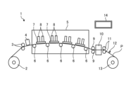
- FIG. 1 is a front view schematically showing the front of a printer according to an embodiment.
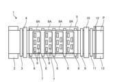
- FIG. 2 is a plan view schematically showing a schematic plane of the printer according to the embodiment.
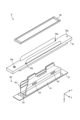
- FIG. 3 is an exploded perspective view showing a schematic configuration of the liquid ejection head according to the embodiment.
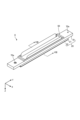
- FIG. 4 is a perspective view showing the configuration of main parts of the liquid ejection head according to the embodiment.
- FIG. 5 is an enlarged plan view of the head main body according to the embodiment.
- FIG. 6 is an enlarged view of the area surrounded by the dashed line shown in FIG.
- FIG. 7 is a cross-sectional view taken along line VII-VII shown in FIG.
- FIG. 8 is an enlarged sectional view taken along line VIII-VIII shown in FIG. 4.
- FIG. 9 is a side view of the protective sheet viewed from the negative direction of the X-axis.
- FIG. 10 is an explanatory diagram for explaining an example of a method of adhering a protective sheet.
- each embodiment can be combined as appropriate within the range that does not conflict with the processing contents. Further, in each of the embodiments below, the same parts are given the same reference numerals, and redundant explanations will be omitted.
- FIG. 1 is a front view schematically showing the front of a printer 1 according to an embodiment.
- FIG. 2 is a plan view schematically showing a schematic plane of the printer 1 according to the embodiment.
- the printer 1 according to the embodiment is, for example, a color inkjet printer.
- the printer 1 includes a paper feed roller 2, a guide roller 3, a coating machine 4, a head case 5, a plurality of transport rollers 6, a plurality of frames 7, and a plurality of liquid ejection heads. 8, a conveyance roller 9, a dryer 10, a conveyance roller 11, a sensor section 12, and a collection roller 13.
- the printer 1 includes a control section 14 that controls each section of the printer 1.
- the control unit 14 includes a paper feed roller 2, a guide roller 3, a coating machine 4, a head case 5, a plurality of transport rollers 6, a plurality of frames 7, a plurality of liquid ejection heads 8, a transport roller 9, a dryer 10, and a transport roller. 11. Controls the operation of the sensor section 12 and collection roller 13.
- the printer 1 records images and characters on the printing paper P by causing droplets to land on the printing paper P.
- Print paper P is an example of a recording medium.
- the printing paper P is wound around the paper feed roller 2 before use.
- the printer 1 transports printing paper P from a paper feed roller 2 through a guide roller 3 and a coater 4 into a head case 5 .
- the coating machine 4 uniformly applies the coating agent to the printing paper P. Thereby, since the printing paper P can be surface-treated, the printing quality of the printer 1 can be improved.
- the head case 5 accommodates a plurality of transport rollers 6, a plurality of frames 7, and a plurality of liquid ejection heads 8. Inside the head case 5, a space is formed that is isolated from the outside except for a portion where the printing paper P enters and exits and is connected to the outside.
- control unit 14 In the internal space of the head case 5, at least one of control factors such as temperature, humidity, and atmospheric pressure is controlled by the control unit 14 as necessary.
- the conveyance roller 6 conveys the printing paper P to the vicinity of the liquid ejection head 8 inside the head case 5 .
- the frame 7 is a rectangular flat plate, and is located close to above the printing paper P conveyed by the conveyance roller 6. Further, as shown in FIG. 2, the frame 7 is positioned such that its longitudinal direction is orthogonal to the conveyance direction of the printing paper P. Inside the head case 5, a plurality of (for example, four) frames 7 are positioned at predetermined intervals along the conveyance direction of the printing paper P.
- a liquid for example, ink
- the liquid ejection head 8 ejects liquid supplied from a liquid tank.
- the control unit 14 controls the liquid ejection head 8 based on data such as images and characters, and causes the liquid to be ejected toward the printing paper P.
- the distance between the liquid ejection head 8 and the printing paper P is, for example, about 0.5 to 20 mm.
- the liquid ejection head 8 is fixed to the frame 7.
- the liquid ejection head 8 is positioned such that its longitudinal direction is perpendicular to the conveyance direction of the printing paper P.
- the printer 1 according to the embodiment is a so-called line printer in which the liquid ejection head 8 is fixed inside the printer 1.
- the printer 1 according to the embodiment is not limited to a line printer, and may be a so-called serial printer.
- a serial printer is a printer that alternately records by moving the liquid ejection head 8 back and forth in a direction intersecting the conveyance direction of the print paper P, for example, in a direction substantially perpendicular to the conveyance direction, and the conveyance of the print paper P. This is a type of printer that uses
- a plurality of (for example, five) liquid ejection heads 8 are fixed to one frame 7.
- FIG. 2 an example is shown in which three liquid ejection heads 8 are located in the front and two liquid ejection heads 8 are located in the rear in the transport direction of the printing paper P.
- the liquid ejection heads 8 are positioned so that their centers do not overlap.
- a plurality of liquid ejection heads 8 located on one frame 7 constitute a head group 8A.
- the four head groups 8A are located along the conveyance direction of the printing paper P. Ink of the same color is supplied to the liquid ejection heads 8 belonging to the same head group 8A. Thereby, the printer 1 can perform printing with four color inks using the four head groups 8A.
- the colors of ink ejected from each head group 8A are, for example, magenta (M), yellow (Y), cyan (C), and black (K).
- the control unit 14 can print a color image on the printing paper P by controlling each head group 8A to eject ink of a plurality of colors onto the printing paper P.
- a coating agent may be ejected onto the printing paper P from the liquid ejection head 8.
- the number of liquid ejection heads 8 included in one head group 8A and the number of head groups 8A mounted on the printer 1 can be changed as appropriate depending on the object to be printed and printing conditions. For example, if the printing paper P is printed in a single color and the range that can be printed with one liquid ejection head 8 is printed, the number of liquid ejection heads 8 installed in the printer 1 may be one. good.
- the printing paper P that has been printed inside the head case 5 is transported to the outside of the head case 5 by transport rollers 9 and passes through the inside of the dryer 10.
- the dryer 10 dries the printed printing paper P.
- the printing paper P dried in the dryer 10 is transported by a transport roller 11 and collected by a collection roller 13.
- the printer 1 by drying the printing paper P in the dryer 10, it is possible to reduce the adhesion of the printing paper P wound up overlappingly to each other and the rubbing of undried liquid on the collection roller 13. can.
- the sensor section 12 is composed of a position sensor, a speed sensor, a temperature sensor, etc.
- the control section 14 can determine the status of each section of the printer 1 based on information from the sensor section 12 and control each section of the printer 1 .
- the printing target in the printer 1 is not limited to the printing paper P, and rolls of cloth etc. You can also use it as the printing paper P, and rolls of cloth etc.
- the printer 1 may place it on a conveyor belt and convey it. By using the conveyor belt, the printer 1 can print on sheets of paper, cut cloth, wood, tiles, and the like.
- the printer 1 may print a wiring pattern of an electronic device, etc. by ejecting a liquid containing conductive particles from the liquid ejection head 8.
- the printer 1 may produce a chemical agent by ejecting a predetermined amount of a liquid chemical agent or a liquid containing a chemical agent from the liquid ejecting head 8 toward a reaction container or the like.
- the printer 1 may include a cleaning section that cleans the liquid ejection head 8.
- the cleaning section cleans the liquid ejection head 8 by, for example, wiping processing or capping processing.
- the wiping process is a process in which liquid adhering to the liquid ejection head 8 is removed by, for example, wiping the surface of the area where the liquid is ejected with a flexible wiper.
- the capping process is performed as follows, for example. First, a cap is placed so as to cover the portion from which the liquid is discharged, for example, the second surface 21b (see FIG. 7) of the channel member 21 (this is called capping). Thereby, a substantially sealed space is formed between the second surface 21b and the cap.
- the liquid is repeatedly discharged in such a sealed space. As a result, it is possible to remove liquid or foreign matter that is clogged in the discharge hole 163 (see FIG. 7) and has a higher viscosity than the standard state.
- FIG. 3 is an exploded perspective view showing a schematic configuration of the liquid ejection head 8 according to the embodiment.
- FIG. 4 is a perspective view showing the configuration of main parts of the liquid ejection head 8 according to the embodiment.
- the liquid ejection head 8 includes a head main body 20, a wiring section 40, and a support member 50.
- the head main body 20 includes a flow path member 21, a piezoelectric actuator substrate 22, and a reservoir 70.
- the wiring section 40 includes flexible substrates 41 and 42 and a drive IC 43.
- FIGS. 3 and 4 illustrate a three-dimensional orthogonal coordinate system including a Z-axis with the vertically downward direction being the positive direction and the vertically upward direction being the negative direction.
- Such an orthogonal coordinate system may also be shown in other drawings used in the description below.
- the direction in which the flow path member 21 of the head main body 20 is provided in the liquid ejection head 8, that is, the Z-axis positive direction side will be referred to as "lower”
- the direction with respect to the flow path member 21 will be referred to as "lower”.
- the direction in which the reservoir 70 is provided, that is, the Z-axis negative direction side may be referred to as "upper”.
- the shapes of each member may be shown in a simplified manner.
- the flow path member 21 has a substantially flat plate shape, and has one main surface, a first surface 21a (see FIG. 7), and a second surface 21b (see FIG. 7) located on the opposite side of the first surface 21a. have.
- the first surface 21a has an opening 161a (see FIG. 5), and liquid is supplied from the reservoir 70 into the channel member 21 through the opening 161a.
- a plurality of ejection holes 163 for ejecting liquid onto the printing paper P are located on the second surface 21b.
- a channel is formed inside the channel member 21 to allow liquid to flow from the first surface 21a to the second surface 21b.
- the piezoelectric actuator substrate 22 is located on the first surface 21a of the flow path member 21.
- the piezoelectric actuator substrate 22 has a plurality of displacement elements 170 (see FIG. 7).
- the displacement element 170 is an example of a pressurizing section.
- the displacement element 170 is located on the first surface 21a of the flow path member 21. Note that the piezoelectric actuator substrate 22 will be described later using FIG. 7.
- Flexible substrates 41 and 42 are electrically connected to the piezoelectric actuator substrate 22.
- the flexible substrates 41 and 42 are flexible wiring substrates, and have a function of transmitting predetermined signals sent from the outside to the head main body 20.
- the liquid ejection head 8 according to the embodiment has two flexible substrates 41 and 42. Note that in FIG. 4, illustration of the flexible substrates 41 and 42 is omitted.
- One end portions 41a, 42a (see FIG. 8) of the flexible substrates 41, 42 are located on the piezoelectric actuator substrate 22 of the head main body 20.
- One end portions 41a and 42a are electrically connected to the piezoelectric actuator substrate 22 of the head main body 20.
- the other end portions of the flexible substrates 41 and 42 are inserted into the slit portion 70b of the reservoir 70 and pulled out from the slit portion 70b above the support member 50 (see FIG. 8), and are connected to other wiring substrates (not shown). electrically connected.
- the flexible substrates 41 and 42 have a connection surface connected to the piezoelectric actuator substrate 22 of the head body 20 and an opposite surface located on the opposite side of the connection surface.
- the drive IC 43 is mounted on the flexible substrates 41 and 42, respectively.
- the drive IC 43 controls the drive of each displacement element 170 on the piezoelectric actuator substrate 22.
- two drive ICs 43 are provided on each of the flexible substrates 41 and 42. Note that the number of drive ICs 43 provided on each of the flexible substrates 41 and 42 is not limited to two.
- the support member 50 is located on the reservoir 70 and supports members other than the members shown in FIGS. 3 and 4, such as a casing that houses the wiring section 40.
- the support member 50 has a rectangular frame shape extending in the longitudinal direction of the liquid ejection head 8, and is located on the reservoir 70 so as to surround a predetermined area including the slit portion 70b in plan view.
- the reservoir 70 is located on the first surface 21a side of the head main body 20 and is in contact with the first surface 21a other than the piezoelectric actuator substrate 22.
- the reservoir 70 has a flow path inside, and liquid is supplied from the outside through an opening 70a.
- the reservoir 70 has a function of supplying liquid to the channel member 21 and a function of storing the supplied liquid.
- liquid ejection head 8 may further include members other than those shown in FIGS. 3 and 4, such as a casing that houses the wiring section 40.
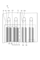
- FIG. 5 is an enlarged plan view of the head main body 20 according to the embodiment.
- FIG. 6 is an enlarged view of the area surrounded by the dashed line shown in FIG.
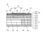
- FIG. 7 is a cross-sectional view taken along line VII-VII shown in FIG. Note that in FIG. 5, the right side area shows the transparent area.
- the head main body 20 includes a flow path member 21 and a piezoelectric actuator substrate 22.
- the flow path member 21 has a supply manifold 161, a plurality of pressurizing chambers 162, and a plurality of discharge holes 163.
- the plurality of pressurizing chambers 162 are connected to the supply manifold 161.
- the plurality of discharge holes 163 are connected to the plurality of pressurizing chambers 162, respectively.
- the pressurizing chamber 162 is open to the first surface 21a (see FIG. 7) of the flow path member 21. Further, the first surface 21a of the flow path member 21 has an opening 161a connected to the supply manifold 161. Then, liquid is supplied from the reservoir 70 (see FIG. 3) into the channel member 21 through the opening 70a.
- the head main body 20 has four supply manifolds 161 inside the flow path member 21.
- the supply manifold 161 has an elongated shape extending along the longitudinal direction of the flow path member 21, and openings 161a of the supply manifold 161 are formed in the first surface 21a of the flow path member 21 at both ends thereof.
- a plurality of pressurizing chambers 162 are formed in the flow path member 21 so as to extend two-dimensionally.
- the pressurizing chamber 162 is a hollow region having a substantially diamond-shaped planar shape with rounded corners.
- the pressurizing chamber 162 is open to the first surface 21a of the flow path member 21, and is closed by joining the piezoelectric actuator substrate 22 to the first surface 21a.
- the pressurizing chambers 162 constitute pressurizing chamber rows arranged in the longitudinal direction.
- the pressurizing chambers 162 in the pressurizing chamber row are arranged in a staggered manner between two adjacent pressurizing chamber rows.
- Two pressurizing chamber rows connected to one supply manifold 161 constitute one pressurizing chamber group.
- the flow path member 21 has four pressurizing chamber groups.
- each pressurizing chamber group is positioned slightly shifted in the longitudinal direction.
- the discharge hole 163 is arranged at a position of the flow path member 21 that avoids a region facing the supply manifold 161. That is, when the channel member 21 is seen through from the first surface 21a side, the discharge holes 163 do not overlap the supply manifold 161.
- the discharge hole 163 is located so as to fit within the mounting area of the piezoelectric actuator substrate 22.
- Such discharge holes 163 occupy an area having substantially the same size and shape as the piezoelectric actuator substrate 22 as one group.
- the channel member 21 has a laminated structure in which a plurality of plates are laminated. These plates include, in order from the first surface 21a side of the channel member 21, a cavity plate 21A, a base plate 21B, an aperture plate 21C, a supply plate 21D, manifold plates 21E, 21F, 21G, a cover plate 21H, and a nozzle plate. 21I is located.
- a large number of holes are formed in the plate that constitutes the flow path member 21.
- the thickness of each plate is approximately 10 ⁇ m to 300 ⁇ m. Thereby, the accuracy of hole formation can be increased.
- the plates are aligned and stacked such that the holes communicate with each other to define individual channels 164 and supply manifolds 161.
- the supply manifold 161 and the discharge hole 163 are connected through an individual flow path 164.
- the supply manifold 161 is located inside the flow path member 21 on the second surface 21b side, and the discharge hole 163 is located on the second surface 21b of the flow path member 21.
- the individual flow path 164 has a pressurizing chamber 162 and an individual supply flow path 165.
- the pressurizing chamber 162 is located on the first surface 21a of the channel member 21, and the individual supply channel 165 is a channel that connects the supply manifold 161 and the pressurizing chamber 162.
- the individual supply channel 165 includes a throttle 166 that is narrower than other parts. Since the throttle 166 is narrower than the other portions of the individual supply channel 165, the flow channel resistance is high. In this way, when the flow path resistance of the throttle 166 is high, the pressure generated in the pressurizing chamber 162 is difficult to escape to the supply manifold 161.
- the piezoelectric actuator substrate 22 includes piezoelectric ceramic layers 22A and 22B, a common electrode 171, an individual electrode 172, a connection electrode 173, a dummy connection electrode 174, and a surface electrode 175 (see FIG. 5).
- the piezoelectric actuator substrate 22 has a piezoelectric ceramic layer 22B, a common electrode 171, a piezoelectric ceramic layer 22A, and an individual electrode 172 stacked in this order.
- the piezoelectric ceramic layers 22A and 22B each have a thickness of about 20 ⁇ m. Both piezoelectric ceramic layers 22A and 22B extend across the plurality of pressurizing chambers 162.
- a lead zirconate titanate (PZT) ceramic material having ferroelectric properties can be used.
- the common electrode 171 is formed over substantially the entire surface in the area between the piezoelectric ceramic layer 22A and the piezoelectric ceramic layer 22B. That is, the common electrode 171 overlaps all the pressurizing chambers 162 in the area facing the piezoelectric actuator substrate 22.
- the thickness of the common electrode 171 is approximately 2 ⁇ m.
- the common electrode 171 can be made of, for example, a metal material such as Ag--Pd.
- the individual electrode 172 includes an individual electrode main body 172a and an extraction electrode 172b.
- the individual electrode body 172a is located on the piezoelectric ceramic layer 22B in a region facing the pressurizing chamber 162.
- the individual electrode main body 172a is one size smaller than the pressurizing chamber 162 and has a shape substantially similar to the pressurizing chamber 162.
- the extraction electrode 172b is extracted from the individual electrode body 172a.
- a connection electrode 173 is located in a portion of one end of the extraction electrode 172b that is extracted outside the area facing the pressurizing chamber 162.
- a metal material such as Au-based material can be used.
- connection electrode 173 is located on the extraction electrode 172b, has a thickness of about 15 ⁇ m, and has a convex shape. Furthermore, the connection electrode 173 is electrically connected to electrodes provided on the flexible substrates 41 and 42 (see FIG. 3).
- connection electrode 173 for example, silver-palladium containing glass frit can be used.
- the dummy connection electrode 174 is located on the piezoelectric ceramic layer 22A, and is located so as not to overlap with various electrodes such as the individual electrodes 172.
- the dummy connection electrode 174 connects the piezoelectric actuator substrate 22 and the flexible substrates 41 and 42 to increase the connection strength.
- the dummy connection electrode 174 equalizes the distribution of contact positions between the piezoelectric actuator substrates 22 and stabilizes the electrical connection.
- the dummy connection electrode 174 is preferably formed using the same material and through the same process as the connection electrode 173.
- the surface electrode 175 is formed on the piezoelectric ceramic layer 22A at a position avoiding the individual electrodes 172.
- the surface electrode 175 is connected to the common electrode 171 via a via hole formed in the piezoelectric ceramic layer 22A. Therefore, the surface electrode 175 is grounded and held at a ground potential.
- the surface electrode 175 is preferably formed using the same material and through the same process as the individual electrodes 172.
- the plurality of individual electrodes 172 are individually electrically connected to the control unit 14 (see FIG. 1) via the flexible substrates 41 and 42 and wiring, in order to individually control the potential. Then, when the individual electrodes 172 and the common electrode 171 are set at different potentials and an electric field is applied in the polarization direction of the piezoelectric ceramic layer 22A, the portion of the piezoelectric ceramic layer 22A to which the electric field is applied becomes an active region that is distorted due to the piezoelectric effect. operates as
- the portions of the individual electrodes 172, the piezoelectric ceramic layer 22A, and the common electrode 171 that face the pressurizing chamber 162 function as the displacement element 170. Then, as the displacement element 170 undergoes unimorph deformation, the pressurizing chamber 162 is pressed, and liquid is discharged from the discharge hole 163.
- the individual electrodes 172 are set in advance to a higher potential than the common electrode 171 (hereinafter referred to as high potential). Then, each time there is a discharge request, the individual electrode 172 is once set to the same potential as the common electrode 171 (hereinafter referred to as low potential), and then set to a high potential again at a predetermined timing.
- the piezoelectric ceramic layers 22A and 22B return to their original shapes at the timing when the individual electrode 172 becomes low in potential, and the volume of the pressurizing chamber 162 increases compared to the initial state (the state in which the potentials of both electrodes are different).
- the pressure applied to the liquid inside the pressurizing chamber 162 increases, and droplets are discharged. That is, in order to eject droplets, a drive signal containing a pulse based on a high potential is supplied to the individual electrodes 172.
- This pulse width may be set to AL (Acoustic Length), which is the length of time that the pressure wave propagates from the aperture 166 to the discharge hole 163.
- AL Acoustic Length
- gradation is expressed by the number of droplets continuously ejected from the ejection holes 163, that is, the amount (volume) of droplets adjusted by the number of droplet ejections. For this reason, droplets are continuously ejected a number of times corresponding to the specified gradation expression from the ejection hole 163 corresponding to the specified dot area.
- the interval between pulses supplied to eject droplets may be set to AL.
- the period of the residual pressure wave of the pressure generated when ejecting the droplet that was ejected first matches the period of the pressure wave of the pressure that occurs when ejecting the droplet that is ejected later. Therefore, the residual pressure wave and the pressure wave are superimposed, and the pressure for ejecting the droplet can be amplified. Note that in this case, the speed of the droplets ejected later becomes faster, and the landing points of the plurality of droplets become closer.
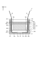
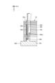
- FIG. 8 is an enlarged sectional view taken along line VIII-VIII shown in FIG. 4.
- the reservoir 70 is located on the first surface 21a of the flow path member 21, and has a housing portion 70c and a slit portion 70b.
- the accommodating portion 70c is a space that accommodates the piezoelectric actuator substrate 22 and one end portions 41a, 42a of the flexible substrates 41, 42 between the accommodating portion 70c and the first surface 21a.
- the slit portion 70b is a groove-shaped void extending along the longitudinal direction (Y-axis direction) of the reservoir 70.
- the slit portion 70b is open on the upper surface of the reservoir 70, and provides communication between the outside of the reservoir 70 and the accommodating portion 70c, which is a space formed inside the reservoir 70.
- the flexible substrates 41 and 42 connected to the piezoelectric actuator board 22 are inserted through the slit portion 70b and drawn out of the reservoir 70 from the slit portion 70b.
- the reservoir 70 has a protective sheet 200 on one inner wall surface 70b1 facing the flexible substrates 41 and 42 in the width direction of the slit portion 70b.
- the inner wall surface 70b1 of the slit portion 70b is located on the outer side of the reservoir 70 in the lateral direction (X-axis direction), and faces the connecting surfaces of the flexible substrates 41 and 42 inserted through the slit portion 70b. That is, the slit portion 70b has an inner wall surface located on the inner side of the reservoir 70 in the transverse direction (X-axis direction) and an inner wall surface 70b1 located on the outer side of the reservoir 70 in the transverse direction (X-axis direction). ing.
- the protective sheet 200 is positioned between the outer inner wall surface 70b1 of the slit section 70b and the flexible substrate 41, and between the outer inner wall surface 70b1 of the slit section 70b and the flexible substrate 42.
- the material of the protective sheet 200 for example, polyethylene terephthalate, polycarbonate, etc. can be used.
- the protective sheet 200 has higher rigidity than the flexible substrates 41 and 42. Due to the high rigidity of the protective sheet 200, the protective sheet 200 can play the role of a guide for guiding the flexible substrates 41 and 42 inserted through the slit portion 70b, improving work efficiency.
- the protective sheet 200 has a first surface and a second surface having a larger surface roughness than the first surface.
- the ten-point average surface roughness (Rz) of the first side of the protective sheet 200 is about 5 ⁇ m
- the ten-point average surface roughness (Rz) of the second side of the protective sheet 200 is about 15 ⁇ m.
- the second surface of the protective sheet 200 which has a large surface roughness, faces the flexible substrates 41 and 42. By directing the second surface of the protective sheet 200 toward the flexible substrates 41, 42, the contact area between the protective sheet 200 and the flexible substrates 41, 42 is reduced, and the flexible substrates 41, 42 can be pulled out from the slit portion 70b. can be facilitated.
- Such a protective sheet 200 may be produced by laminating protective sheets having the above-mentioned surface roughness, or may be produced by surface processing so as to have the above-mentioned surface roughness.
- the protective sheet 200 is adhered to the inner wall surface 70b1 of the slit portion 70b via an adhesive member 300.
- the adhesive member 300 is, for example, double-sided tape.
- the reservoir 70 has a laminated structure in which a plurality of plates are laminated.
- plates 70A to 70E are located in order from the upper surface side of the reservoir 70.
- a large number of holes are formed in the plurality of plates 70A to 70E that constitute the reservoir 70.
- the plurality of plates 70A to 70E are aligned and stacked so that the holes communicate with each other to form the housing portion 70c and the slit portion 70b.
- the slit portion 70b is formed by the holes in the plates 70A to 70C communicating with each other
- the accommodating portion 70c is formed by the holes in the plates 70D and 70E communicating with each other.
- the protective sheet 200 is bonded via an adhesive member 300 to the inner wall surface 70b1 of the hole of at least the thickest plate among the plates 70A to 70C.
- the plate 70C is the thickest among the plates 70A to 70C, so the protective sheet 200 is adhered to the inner wall surface 70b1 of the hole of the plate 70C via the adhesive member 300.
- the adhesive strength between the protective sheet 200 and the inner wall surface 70b1 of the slit portion 70b can be maintained.
- the protective sheet 200 may be bonded via the adhesive member 300 to the inner wall surface 70b1 of the hole in the plate 70B or plate 70D adjacent to the plate 70C.
- the protective sheet 200 has a protrusion 201 that protrudes above the upper end of the support member 50 from the slit portion 70b. Therefore, the protective sheet 200 can play the role of a guide for guiding the placement of the support member 50 on the reservoir 70, and can accurately position the support member 50 on the reservoir 70. Further, the protective sheet 200 can play the role of a wall that shields the slit portion 70b from the interface between the reservoir 70 and the support member 50, and the adhesive 400 described below for bonding the reservoir 70 and the support member 50 is applied to the slit portion. The risk of intrusion into 70b can be reduced.
- the protective sheet 200 is in contact with the flexible substrates 41 and 42 that are pulled out from the slit portion 70b above the upper end of the support member 50 at the protruding portion 201. Therefore, it is possible to avoid contact between the upper end of the support member 50 and the flexible substrates 41 and 42 that are pulled out above the upper end of the support member 50, further reducing the risk of damage to the flexible substrates 41 and 42. be able to.
- the protective sheet 200 has chamfered portions 201a at the corners of the protruding portions 201.
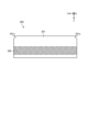
- FIG. 9 is a side view of the protective sheet 200 viewed from the negative direction of the X-axis. Since the protective sheet 200 has the chamfered portion 201a at the corner of the protruding portion 201, interference between the protective sheet 200 and the supporting member 50 is reduced when the supporting member 50 is placed on the reservoir 70 using the protective sheet 200 as a guide. This improves work efficiency.
- the protective sheet 200 has an end portion 202 that is not bonded to the inner wall surface 70b1 of the slit portion 70b.
- This end portion 202 is located close to the connection portion between the flexible substrates 41, 42 and the piezoelectric actuator substrate 22 (that is, one end portion 41a, 42a of the flexible substrates 41, 42). Therefore, the end portion 202 of the protective sheet 200 whose movement is not restricted can be located near the connecting portion between the flexible substrates 41, 42 and the piezoelectric actuator substrate 22, and the flexible substrates 41, 42 can be moved from the slit portion 70b. Withdrawals can be made easier.
- the support member 50 is bonded onto the reservoir 70 via an adhesive 400.
- a portion of the adhesive 400 oozes out from the interface between the support member 50 and the reservoir 70 and is located between the inner wall surface of the support member 50 and the protective sheet 200.
- the protective sheet 200 is adhered to the inner wall surface 70b1 of the slit portion 70b via the adhesive member 300, It is adhered to the inner wall surface of the support member 50 via an adhesive 400. Therefore, the adhesive strength of the protective sheet 200 is improved, and the possibility that the protective sheet 200 and the inner wall surface 70b1 of the slit portion 70b will peel off can be reduced.
- FIG. 10 is an explanatory diagram for explaining an example of a method of adhering the protective sheet 200.
- a jig 500 is used in the method of bonding the protective sheet 200.
- the jig 500 includes a plate-shaped base portion 501 and a pedestal portion 502 that rises from the base portion 501 and has a tapered surface 502a.
- the protective sheet 200 is placed on the pedestal part 502 in a tilted state along the tapered surface 502a, and is inserted into the slit part 70b of the reservoir 70 together with the pedestal part 502.
- the protective sheet 200 placed on the pedestal portion 502 is indicated by a broken line.
- An adhesive member 300 which is a double-sided tape, is attached to the protective sheet 200 in advance.
- the protective sheet 200 is rotated on the pedestal section 502 in a direction away from the tapered surface 502a, so that the adhesive member 300 is attached to the inner wall surface 70b1 of the slit section 70b. Thereby, the protective sheet 200 is adhered to the inner wall surface 70b1 of the slit portion 70b via the adhesive member 300. Thereafter, the pedestal section 502 is pulled out from the slit section 70b of the reservoir 70.
- the protective sheet 200 has the protrusion 201 that protrudes upward from the upper end of the support member 50 from the slit portion 70b has been described as an example, but a configuration in which the protrusion 201 is omitted is adopted. You can also do that. That is, the protective sheet 200 may extend from the slit portion 70b to the upper end of the support member 50.
- the liquid ejection head (e.g., liquid ejection head 8) according to the embodiment includes a flow path member (e.g., flow path member 21), a pressure section (e.g., displacement element 170), and a flexible substrate (
- a flow path member e.g., flow path member 21
- a pressure section e.g., displacement element 170
- a flexible substrate for example, it includes flexible substrates 41, 42
- the channel member has a discharge hole (for example, discharge hole 163) that discharges liquid.
- the pressurizing section is located on the channel member.
- the flexible substrate is electrically connected to the pressurizing section.
- the reservoir has a slit portion (for example, slit portion 70b) through which the flexible substrate is inserted, and supplies liquid to the channel member.
- the reservoir has a protective sheet (for example, the protective sheet 200) on one inner wall surface (for example, the inner wall surface 70b1) facing the flexible substrate in the width direction of the slit portion.
- a protective sheet for example, the protective sheet 200
- one inner wall surface for example, the inner wall surface 70b1 facing the flexible substrate in the width direction of the slit portion.
- the liquid ejection head according to the embodiment may further include a frame-shaped support member (for example, support member 50) located on the reservoir so as to surround a predetermined area including the slit portion in plan view.
- the protective sheet may have a protrusion (for example, the protrusion 201) that protrudes from the slit above the upper end of the support member.
- the protective sheet may come into contact with the flexible substrate pulled out from the slit above the upper end of the support member at the protrusion.
- the protective sheet may have chamfered portions at the corners of the protruding portions.
- the protective sheet may have a first surface and a second surface having a larger surface roughness than the first surface, and the second surface may be directed toward the flexible substrate side.
- the protective sheet may have higher rigidity than the flexible substrate.
- the protective sheet may be adhered to one inner wall surface of the slit portion via an adhesive member (for example, the adhesive member 300).
- an adhesive member for example, the adhesive member 300.
- the reservoir may have a laminated structure in which a plurality of plates (for example, plates 70A to 70E) are laminated.
- the plurality of plates may include one or more plates (eg, plates 70A-70C) having holes that form slits.
- the protective sheet may be adhered to one inner wall surface of the hole of at least the thickest plate (for example, plate 70C) among the one or more plates via an adhesive member.
- the protective sheet may have an end portion (for example, the end portion 202) that is not adhered to one inner wall surface of the slit portion.
- the end portion may be located close to the connection portion between the flexible substrate and the pressurizing portion.
- the support member may be adhered onto the reservoir via an adhesive (for example, adhesive 400).
- a portion of the adhesive may be located between the inner wall surface of the support member and the protective sheet.
Landscapes
- Engineering & Computer Science (AREA)
- Manufacturing & Machinery (AREA)
- Particle Formation And Scattering Control In Inkjet Printers (AREA)
Priority Applications (3)
| Application Number | Priority Date | Filing Date | Title |
|---|---|---|---|
| CN202380062803.7A CN119789960A (zh) | 2022-08-29 | 2023-08-28 | 液体喷出头及记录装置 |
| EP23860288.2A EP4582257A4 (en) | 2022-08-29 | 2023-08-28 | LIQUID EJECTION HEAD AND PRINTING DEVICE |
| JP2024544249A JPWO2024048526A1 (cg-RX-API-DMAC7.html) | 2022-08-29 | 2023-08-28 |
Applications Claiming Priority (2)
| Application Number | Priority Date | Filing Date | Title |
|---|---|---|---|
| JP2022-136359 | 2022-08-29 | ||
| JP2022136359 | 2022-08-29 |
Publications (1)
| Publication Number | Publication Date |
|---|---|
| WO2024048526A1 true WO2024048526A1 (ja) | 2024-03-07 |
Family
ID=90099954
Family Applications (1)
| Application Number | Title | Priority Date | Filing Date |
|---|---|---|---|
| PCT/JP2023/031013 Ceased WO2024048526A1 (ja) | 2022-08-29 | 2023-08-28 | 液体吐出ヘッドおよび記録装置 |
Country Status (4)
| Country | Link |
|---|---|
| EP (1) | EP4582257A4 (cg-RX-API-DMAC7.html) |
| JP (1) | JPWO2024048526A1 (cg-RX-API-DMAC7.html) |
| CN (1) | CN119789960A (cg-RX-API-DMAC7.html) |
| WO (1) | WO2024048526A1 (cg-RX-API-DMAC7.html) |
Citations (8)
| Publication number | Priority date | Publication date | Assignee | Title |
|---|---|---|---|---|
| JP2010227759A (ja) | 2009-03-26 | 2010-10-14 | Seiko Epson Corp | 液滴吐出ヘッド、液滴吐出ヘッドの製造方法、及び液滴吐出装置 |
| JP2012209436A (ja) * | 2011-03-30 | 2012-10-25 | Fujifilm Corp | フレキシブル配線回路基板の接続構造体及びその接続方法 |
| JP2013166261A (ja) * | 2012-02-14 | 2013-08-29 | Ricoh Co Ltd | インクジェット式記録ヘッドおよびインクジェット式記録装置 |
| JP2016164004A (ja) * | 2016-06-15 | 2016-09-08 | セイコーエプソン株式会社 | 液体噴射ヘッドおよび液体噴射装置 |
| JP2019130826A (ja) * | 2018-01-31 | 2019-08-08 | セイコーエプソン株式会社 | プリントヘッド |
| JP2019188716A (ja) * | 2018-04-26 | 2019-10-31 | ブラザー工業株式会社 | 記録装置及び配線部材 |
| JP2020015209A (ja) * | 2018-07-25 | 2020-01-30 | 東芝テック株式会社 | インクジェットヘッド及びインクジェット記録装置 |
| JP2021053902A (ja) * | 2019-09-30 | 2021-04-08 | 京セラ株式会社 | 液体吐出ヘッドおよび記録装置 |
Family Cites Families (1)
| Publication number | Priority date | Publication date | Assignee | Title |
|---|---|---|---|---|
| JP6281221B2 (ja) * | 2013-09-27 | 2018-02-21 | コニカミノルタ株式会社 | インクジェットヘッド及びインクジェットヘッドの製造方法 |
-
2023
- 2023-08-28 JP JP2024544249A patent/JPWO2024048526A1/ja active Pending
- 2023-08-28 WO PCT/JP2023/031013 patent/WO2024048526A1/ja not_active Ceased
- 2023-08-28 CN CN202380062803.7A patent/CN119789960A/zh active Pending
- 2023-08-28 EP EP23860288.2A patent/EP4582257A4/en active Pending
Patent Citations (8)
| Publication number | Priority date | Publication date | Assignee | Title |
|---|---|---|---|---|
| JP2010227759A (ja) | 2009-03-26 | 2010-10-14 | Seiko Epson Corp | 液滴吐出ヘッド、液滴吐出ヘッドの製造方法、及び液滴吐出装置 |
| JP2012209436A (ja) * | 2011-03-30 | 2012-10-25 | Fujifilm Corp | フレキシブル配線回路基板の接続構造体及びその接続方法 |
| JP2013166261A (ja) * | 2012-02-14 | 2013-08-29 | Ricoh Co Ltd | インクジェット式記録ヘッドおよびインクジェット式記録装置 |
| JP2016164004A (ja) * | 2016-06-15 | 2016-09-08 | セイコーエプソン株式会社 | 液体噴射ヘッドおよび液体噴射装置 |
| JP2019130826A (ja) * | 2018-01-31 | 2019-08-08 | セイコーエプソン株式会社 | プリントヘッド |
| JP2019188716A (ja) * | 2018-04-26 | 2019-10-31 | ブラザー工業株式会社 | 記録装置及び配線部材 |
| JP2020015209A (ja) * | 2018-07-25 | 2020-01-30 | 東芝テック株式会社 | インクジェットヘッド及びインクジェット記録装置 |
| JP2021053902A (ja) * | 2019-09-30 | 2021-04-08 | 京セラ株式会社 | 液体吐出ヘッドおよび記録装置 |
Non-Patent Citations (1)
| Title |
|---|
| See also references of EP4582257A4 |
Also Published As
| Publication number | Publication date |
|---|---|
| CN119789960A (zh) | 2025-04-08 |
| EP4582257A4 (en) | 2026-01-07 |
| EP4582257A1 (en) | 2025-07-09 |
| JPWO2024048526A1 (cg-RX-API-DMAC7.html) | 2024-03-07 |
Similar Documents
| Publication | Publication Date | Title |
|---|---|---|
| US20140184697A1 (en) | Liquid jet head and liquid jet apparatus | |
| JP7268133B2 (ja) | 液体吐出ヘッドおよび記録装置 | |
| CN114423615B (zh) | 液体喷出头以及记录装置 | |
| JP7328105B2 (ja) | 液体吐出ヘッドおよび記録装置 | |
| JP7189970B2 (ja) | 液体吐出ヘッドおよび記録装置 | |
| CN114867609B (zh) | 液体喷出头以及记录装置 | |
| JP7361785B2 (ja) | 液体吐出ヘッドおよび記録装置 | |
| EP4582257A1 (en) | Liquid ejection head and recording device | |
| JP7221992B2 (ja) | 液体吐出ヘッドおよび記録装置 | |
| JP7215972B2 (ja) | 液体吐出ヘッドおよび記録装置 | |
| JP2021104665A (ja) | 液体吐出ヘッド及び記録装置 | |
| JP7664395B2 (ja) | 液体吐出ヘッドおよび記録装置 | |
| EP4501645A1 (en) | Liquid discharge head and recording device | |
| JP7615417B1 (ja) | 液滴吐出ヘッドおよび記録装置 | |
| JP7288073B2 (ja) | 液滴吐出ヘッド及び記録装置 | |
| WO2024248058A1 (ja) | 液滴吐出ヘッドおよび記録装置 | |
| JP2023157672A (ja) | 液体吐出ヘッドおよび記録装置 | |
| WO2023191005A1 (ja) | 液滴吐出ヘッドおよび記録装置 | |
| WO2023176700A1 (ja) | 液体吐出ヘッドおよび記録装置 | |
| WO2023176549A1 (ja) | 圧電アクチュエータ、液体吐出ヘッドおよび記録装置 |
Legal Events
| Date | Code | Title | Description |
|---|---|---|---|
| 121 | Ep: the epo has been informed by wipo that ep was designated in this application |
Ref document number: 23860288 Country of ref document: EP Kind code of ref document: A1 |
|
| WWE | Wipo information: entry into national phase |
Ref document number: 2024544249 Country of ref document: JP Ref document number: 202380062803.7 Country of ref document: CN |
|
| WWE | Wipo information: entry into national phase |
Ref document number: 2023860288 Country of ref document: EP |
|
| NENP | Non-entry into the national phase |
Ref country code: DE |
|
| ENP | Entry into the national phase |
Ref document number: 2023860288 Country of ref document: EP Effective date: 20250331 |
|
| WWP | Wipo information: published in national office |
Ref document number: 202380062803.7 Country of ref document: CN |
|
| WWP | Wipo information: published in national office |
Ref document number: 2023860288 Country of ref document: EP |