WO2024048467A1 - アンモニア分解触媒および排ガス処理方法 - Google Patents
アンモニア分解触媒および排ガス処理方法 Download PDFInfo
- Publication number
- WO2024048467A1 WO2024048467A1 PCT/JP2023/030794 JP2023030794W WO2024048467A1 WO 2024048467 A1 WO2024048467 A1 WO 2024048467A1 JP 2023030794 W JP2023030794 W JP 2023030794W WO 2024048467 A1 WO2024048467 A1 WO 2024048467A1
- Authority
- WO
- WIPO (PCT)
- Prior art keywords
- catalyst
- gas
- powder
- treated
- catalyst powder
- Prior art date
Links
- 239000003054 catalyst Substances 0.000 title claims abstract description 476
- QGZKDVFQNNGYKY-UHFFFAOYSA-N Ammonia Chemical compound N QGZKDVFQNNGYKY-UHFFFAOYSA-N 0.000 title claims abstract description 159
- 229910021529 ammonia Inorganic materials 0.000 title claims abstract description 65
- 238000000354 decomposition reaction Methods 0.000 title claims abstract description 62
- 238000000034 method Methods 0.000 title claims abstract description 38
- 239000000843 powder Substances 0.000 claims abstract description 254
- 239000007789 gas Substances 0.000 claims abstract description 192
- HNPSIPDUKPIQMN-UHFFFAOYSA-N dioxosilane;oxo(oxoalumanyloxy)alumane Chemical compound O=[Si]=O.O=[Al]O[Al]=O HNPSIPDUKPIQMN-UHFFFAOYSA-N 0.000 claims abstract description 97
- 239000010457 zeolite Substances 0.000 claims abstract description 95
- 229910021536 Zeolite Inorganic materials 0.000 claims abstract description 93
- GWEVSGVZZGPLCZ-UHFFFAOYSA-N Titan oxide Chemical compound O=[Ti]=O GWEVSGVZZGPLCZ-UHFFFAOYSA-N 0.000 claims abstract description 92
- VYPSYNLAJGMNEJ-UHFFFAOYSA-N Silicium dioxide Chemical compound O=[Si]=O VYPSYNLAJGMNEJ-UHFFFAOYSA-N 0.000 claims abstract description 79
- 238000006243 chemical reaction Methods 0.000 claims abstract description 44
- XLYOFNOQVPJJNP-UHFFFAOYSA-N water Substances O XLYOFNOQVPJJNP-UHFFFAOYSA-N 0.000 claims abstract description 33
- IJGRMHOSHXDMSA-UHFFFAOYSA-N Atomic nitrogen Chemical compound N#N IJGRMHOSHXDMSA-UHFFFAOYSA-N 0.000 claims abstract description 30
- 239000000377 silicon dioxide Substances 0.000 claims abstract description 27
- 239000000203 mixture Substances 0.000 claims abstract description 24
- 229910000510 noble metal Inorganic materials 0.000 claims abstract description 22
- 229910052757 nitrogen Inorganic materials 0.000 claims abstract description 16
- 238000005342 ion exchange Methods 0.000 claims abstract description 15
- 229910000069 nitrogen hydride Inorganic materials 0.000 claims abstract description 15
- 230000001737 promoting effect Effects 0.000 claims abstract description 8
- BASFCYQUMIYNBI-UHFFFAOYSA-N platinum Chemical compound [Pt] BASFCYQUMIYNBI-UHFFFAOYSA-N 0.000 claims description 71
- 150000002500 ions Chemical class 0.000 claims description 37
- 229910052697 platinum Inorganic materials 0.000 claims description 35
- MCMNRKCIXSYSNV-UHFFFAOYSA-N Zirconium dioxide Chemical compound O=[Zr]=O MCMNRKCIXSYSNV-UHFFFAOYSA-N 0.000 claims description 24
- XEEYBQQBJWHFJM-UHFFFAOYSA-N iron Substances [Fe] XEEYBQQBJWHFJM-UHFFFAOYSA-N 0.000 claims description 21
- 229910052684 Cerium Inorganic materials 0.000 claims description 18
- GWXLDORMOJMVQZ-UHFFFAOYSA-N cerium Chemical compound [Ce] GWXLDORMOJMVQZ-UHFFFAOYSA-N 0.000 claims description 18
- PNEYBMLMFCGWSK-UHFFFAOYSA-N aluminium oxide Inorganic materials [O-2].[O-2].[O-2].[Al+3].[Al+3] PNEYBMLMFCGWSK-UHFFFAOYSA-N 0.000 claims description 17
- 238000001816 cooling Methods 0.000 claims description 14
- 239000010949 copper Substances 0.000 claims description 12
- 239000010936 titanium Substances 0.000 claims description 12
- CETPSERCERDGAM-UHFFFAOYSA-N ceric oxide Chemical compound O=[Ce]=O CETPSERCERDGAM-UHFFFAOYSA-N 0.000 claims description 10
- 229910000422 cerium(IV) oxide Inorganic materials 0.000 claims description 10
- WFKWXMTUELFFGS-UHFFFAOYSA-N tungsten Chemical compound [W] WFKWXMTUELFFGS-UHFFFAOYSA-N 0.000 claims description 10
- 229910052721 tungsten Inorganic materials 0.000 claims description 10
- 239000010937 tungsten Substances 0.000 claims description 10
- RTAQQCXQSZGOHL-UHFFFAOYSA-N Titanium Chemical compound [Ti] RTAQQCXQSZGOHL-UHFFFAOYSA-N 0.000 claims description 9
- 229910052741 iridium Inorganic materials 0.000 claims description 9
- GKOZUEZYRPOHIO-UHFFFAOYSA-N iridium atom Chemical compound [Ir] GKOZUEZYRPOHIO-UHFFFAOYSA-N 0.000 claims description 9
- 229910052742 iron Inorganic materials 0.000 claims description 9
- 229910052719 titanium Inorganic materials 0.000 claims description 9
- 229910052720 vanadium Inorganic materials 0.000 claims description 7
- ZOKXTWBITQBERF-UHFFFAOYSA-N Molybdenum Chemical compound [Mo] ZOKXTWBITQBERF-UHFFFAOYSA-N 0.000 claims description 6
- 229910052750 molybdenum Inorganic materials 0.000 claims description 6
- 239000011733 molybdenum Substances 0.000 claims description 6
- XSQUKJJJFZCRTK-UHFFFAOYSA-N Urea Chemical compound NC(N)=O XSQUKJJJFZCRTK-UHFFFAOYSA-N 0.000 claims description 5
- 239000004202 carbamide Substances 0.000 claims description 5
- LEONUFNNVUYDNQ-UHFFFAOYSA-N vanadium atom Chemical compound [V] LEONUFNNVUYDNQ-UHFFFAOYSA-N 0.000 claims description 2
- JUJWROOIHBZHMG-UHFFFAOYSA-N Pyridine Chemical compound C1=CC=NC=C1 JUJWROOIHBZHMG-UHFFFAOYSA-N 0.000 description 44
- 239000002002 slurry Substances 0.000 description 32
- 239000000047 product Substances 0.000 description 28
- 238000010304 firing Methods 0.000 description 23
- UMJSCPRVCHMLSP-UHFFFAOYSA-N pyridine Natural products COC1=CC=CN=C1 UMJSCPRVCHMLSP-UHFFFAOYSA-N 0.000 description 22
- GQPLMRYTRLFLPF-UHFFFAOYSA-N Nitrous Oxide Chemical compound [O-][N+]#N GQPLMRYTRLFLPF-UHFFFAOYSA-N 0.000 description 21
- 239000002253 acid Substances 0.000 description 20
- 239000002245 particle Substances 0.000 description 18
- 238000011156 evaluation Methods 0.000 description 16
- 238000002360 preparation method Methods 0.000 description 16
- 239000007864 aqueous solution Substances 0.000 description 15
- 238000010586 diagram Methods 0.000 description 15
- OGIDPMRJRNCKJF-UHFFFAOYSA-N titanium oxide Inorganic materials [Ti]=O OGIDPMRJRNCKJF-UHFFFAOYSA-N 0.000 description 15
- 238000009826 distribution Methods 0.000 description 14
- 238000002485 combustion reaction Methods 0.000 description 13
- 239000011248 coating agent Substances 0.000 description 12
- 238000000576 coating method Methods 0.000 description 12
- 238000001035 drying Methods 0.000 description 12
- 229910018072 Al 2 O 3 Inorganic materials 0.000 description 11
- 229910004298 SiO 2 Inorganic materials 0.000 description 11
- 239000011734 sodium Substances 0.000 description 11
- 239000000758 substrate Substances 0.000 description 11
- 239000002351 wastewater Substances 0.000 description 11
- 230000006866 deterioration Effects 0.000 description 10
- 239000000446 fuel Substances 0.000 description 10
- 239000007788 liquid Substances 0.000 description 10
- 230000007246 mechanism Effects 0.000 description 10
- 229910004631 Ce(NO3)3.6H2O Inorganic materials 0.000 description 9
- MUBZPKHOEPUJKR-UHFFFAOYSA-N Oxalic acid Chemical compound OC(=O)C(O)=O MUBZPKHOEPUJKR-UHFFFAOYSA-N 0.000 description 9
- 239000011575 calcium Substances 0.000 description 9
- 230000000694 effects Effects 0.000 description 9
- 229910052751 metal Inorganic materials 0.000 description 9
- 238000002156 mixing Methods 0.000 description 9
- -1 gobbinsite Inorganic materials 0.000 description 8
- 150000004687 hexahydrates Chemical class 0.000 description 8
- 238000007254 oxidation reaction Methods 0.000 description 8
- 239000011148 porous material Substances 0.000 description 8
- 239000004576 sand Substances 0.000 description 8
- MWUXSHHQAYIFBG-UHFFFAOYSA-N Nitric oxide Chemical compound O=[N] MWUXSHHQAYIFBG-UHFFFAOYSA-N 0.000 description 7
- KDLHZDBZIXYQEI-UHFFFAOYSA-N Palladium Chemical compound [Pd] KDLHZDBZIXYQEI-UHFFFAOYSA-N 0.000 description 7
- 230000032683 aging Effects 0.000 description 7
- QQZMWMKOWKGPQY-UHFFFAOYSA-N cerium(3+);trinitrate;hexahydrate Chemical compound O.O.O.O.O.O.[Ce+3].[O-][N+]([O-])=O.[O-][N+]([O-])=O.[O-][N+]([O-])=O QQZMWMKOWKGPQY-UHFFFAOYSA-N 0.000 description 7
- 229910021645 metal ion Inorganic materials 0.000 description 7
- 239000002994 raw material Substances 0.000 description 7
- CURLTUGMZLYLDI-UHFFFAOYSA-N Carbon dioxide Chemical compound O=C=O CURLTUGMZLYLDI-UHFFFAOYSA-N 0.000 description 6
- HEMHJVSKTPXQMS-UHFFFAOYSA-M Sodium hydroxide Chemical compound [OH-].[Na+] HEMHJVSKTPXQMS-UHFFFAOYSA-M 0.000 description 6
- 238000004519 manufacturing process Methods 0.000 description 6
- 230000003647 oxidation Effects 0.000 description 6
- 238000001179 sorption measurement Methods 0.000 description 6
- 238000001228 spectrum Methods 0.000 description 6
- GPPXJZIENCGNKB-UHFFFAOYSA-N vanadium Chemical compound [V]#[V] GPPXJZIENCGNKB-UHFFFAOYSA-N 0.000 description 6
- 229910010413 TiO 2 Inorganic materials 0.000 description 5
- 230000008859 change Effects 0.000 description 5
- 238000000227 grinding Methods 0.000 description 5
- 238000005259 measurement Methods 0.000 description 5
- 239000002184 metal Substances 0.000 description 5
- 229910052680 mordenite Inorganic materials 0.000 description 5
- 230000009467 reduction Effects 0.000 description 5
- 238000006722 reduction reaction Methods 0.000 description 5
- 229920006395 saturated elastomer Polymers 0.000 description 5
- 238000003756 stirring Methods 0.000 description 5
- QGZKDVFQNNGYKY-UHFFFAOYSA-O Ammonium Chemical compound [NH4+] QGZKDVFQNNGYKY-UHFFFAOYSA-O 0.000 description 4
- KWYUFKZDYYNOTN-UHFFFAOYSA-M Potassium hydroxide Chemical compound [OH-].[K+] KWYUFKZDYYNOTN-UHFFFAOYSA-M 0.000 description 4
- 238000001354 calcination Methods 0.000 description 4
- 229910052760 oxygen Inorganic materials 0.000 description 4
- 239000000126 substance Substances 0.000 description 4
- CDBYLPFSWZWCQE-UHFFFAOYSA-L Sodium Carbonate Chemical compound [Na+].[Na+].[O-]C([O-])=O CDBYLPFSWZWCQE-UHFFFAOYSA-L 0.000 description 3
- 239000002585 base Substances 0.000 description 3
- 239000001569 carbon dioxide Substances 0.000 description 3
- 229910002092 carbon dioxide Inorganic materials 0.000 description 3
- 229910000420 cerium oxide Inorganic materials 0.000 description 3
- 229910052802 copper Inorganic materials 0.000 description 3
- 239000013078 crystal Substances 0.000 description 3
- 229910052675 erionite Inorganic materials 0.000 description 3
- 239000008187 granular material Substances 0.000 description 3
- 229910052739 hydrogen Inorganic materials 0.000 description 3
- 229910052809 inorganic oxide Inorganic materials 0.000 description 3
- SURQXAFEQWPFPV-UHFFFAOYSA-L iron(2+) sulfate heptahydrate Chemical compound O.O.O.O.O.O.O.[Fe+2].[O-]S([O-])(=O)=O SURQXAFEQWPFPV-UHFFFAOYSA-L 0.000 description 3
- 239000011777 magnesium Substances 0.000 description 3
- QGLKJKCYBOYXKC-UHFFFAOYSA-N nonaoxidotritungsten Chemical compound O=[W]1(=O)O[W](=O)(=O)O[W](=O)(=O)O1 QGLKJKCYBOYXKC-UHFFFAOYSA-N 0.000 description 3
- 235000006408 oxalic acid Nutrition 0.000 description 3
- BMMGVYCKOGBVEV-UHFFFAOYSA-N oxo(oxoceriooxy)cerium Chemical compound [Ce]=O.O=[Ce]=O BMMGVYCKOGBVEV-UHFFFAOYSA-N 0.000 description 3
- 229910052763 palladium Inorganic materials 0.000 description 3
- BWHMMNNQKKPAPP-UHFFFAOYSA-L potassium carbonate Substances [K+].[K+].[O-]C([O-])=O BWHMMNNQKKPAPP-UHFFFAOYSA-L 0.000 description 3
- 238000010926 purge Methods 0.000 description 3
- 229910052761 rare earth metal Inorganic materials 0.000 description 3
- 239000010948 rhodium Substances 0.000 description 3
- 229910052708 sodium Inorganic materials 0.000 description 3
- 229910001930 tungsten oxide Inorganic materials 0.000 description 3
- IBMCQJYLPXUOKM-UHFFFAOYSA-N 1,2,2,6,6-pentamethyl-3h-pyridine Chemical compound CN1C(C)(C)CC=CC1(C)C IBMCQJYLPXUOKM-UHFFFAOYSA-N 0.000 description 2
- XVMSFILGAMDHEY-UHFFFAOYSA-N 6-(4-aminophenyl)sulfonylpyridin-3-amine Chemical compound C1=CC(N)=CC=C1S(=O)(=O)C1=CC=C(N)C=N1 XVMSFILGAMDHEY-UHFFFAOYSA-N 0.000 description 2
- UGFAIRIUMAVXCW-UHFFFAOYSA-N Carbon monoxide Chemical compound [O+]#[C-] UGFAIRIUMAVXCW-UHFFFAOYSA-N 0.000 description 2
- VEXZGXHMUGYJMC-UHFFFAOYSA-N Hydrochloric acid Chemical compound Cl VEXZGXHMUGYJMC-UHFFFAOYSA-N 0.000 description 2
- FYYHWMGAXLPEAU-UHFFFAOYSA-N Magnesium Chemical compound [Mg] FYYHWMGAXLPEAU-UHFFFAOYSA-N 0.000 description 2
- 229910002651 NO3 Inorganic materials 0.000 description 2
- NHNBFGGVMKEFGY-UHFFFAOYSA-N Nitrate Chemical compound [O-][N+]([O-])=O NHNBFGGVMKEFGY-UHFFFAOYSA-N 0.000 description 2
- NBIIXXVUZAFLBC-UHFFFAOYSA-N Phosphoric acid Chemical compound OP(O)(O)=O NBIIXXVUZAFLBC-UHFFFAOYSA-N 0.000 description 2
- 239000012298 atmosphere Substances 0.000 description 2
- 239000012752 auxiliary agent Substances 0.000 description 2
- UNTBPXHCXVWYOI-UHFFFAOYSA-O azanium;oxido(dioxo)vanadium Chemical compound [NH4+].[O-][V](=O)=O UNTBPXHCXVWYOI-UHFFFAOYSA-O 0.000 description 2
- 229910002091 carbon monoxide Inorganic materials 0.000 description 2
- 238000010531 catalytic reduction reaction Methods 0.000 description 2
- 150000001768 cations Chemical class 0.000 description 2
- VZDYWEUILIUIDF-UHFFFAOYSA-J cerium(4+);disulfate Chemical compound [Ce+4].[O-]S([O-])(=O)=O.[O-]S([O-])(=O)=O VZDYWEUILIUIDF-UHFFFAOYSA-J 0.000 description 2
- 229910000355 cerium(IV) sulfate Inorganic materials 0.000 description 2
- 239000006185 dispersion Substances 0.000 description 2
- GNTDGMZSJNCJKK-UHFFFAOYSA-N divanadium pentaoxide Chemical compound O=[V](=O)O[V](=O)=O GNTDGMZSJNCJKK-UHFFFAOYSA-N 0.000 description 2
- 239000010840 domestic wastewater Substances 0.000 description 2
- 239000003651 drinking water Substances 0.000 description 2
- 235000020188 drinking water Nutrition 0.000 description 2
- 238000001704 evaporation Methods 0.000 description 2
- 229910001657 ferrierite group Inorganic materials 0.000 description 2
- 229910001686 gmelinite-K Inorganic materials 0.000 description 2
- 238000005469 granulation Methods 0.000 description 2
- 230000003179 granulation Effects 0.000 description 2
- 239000010440 gypsum Substances 0.000 description 2
- 229910052602 gypsum Inorganic materials 0.000 description 2
- 229910001695 heulandite-Sr Inorganic materials 0.000 description 2
- 238000001027 hydrothermal synthesis Methods 0.000 description 2
- 238000004898 kneading Methods 0.000 description 2
- 229910052749 magnesium Inorganic materials 0.000 description 2
- 239000000463 material Substances 0.000 description 2
- 239000011812 mixed powder Substances 0.000 description 2
- JKQOBWVOAYFWKG-UHFFFAOYSA-N molybdenum trioxide Chemical compound O=[Mo](=O)=O JKQOBWVOAYFWKG-UHFFFAOYSA-N 0.000 description 2
- 238000012544 monitoring process Methods 0.000 description 2
- 239000001272 nitrous oxide Substances 0.000 description 2
- 239000012466 permeate Substances 0.000 description 2
- 230000000704 physical effect Effects 0.000 description 2
- 238000007747 plating Methods 0.000 description 2
- 239000002243 precursor Substances 0.000 description 2
- 230000008569 process Effects 0.000 description 2
- 238000012545 processing Methods 0.000 description 2
- 229910052703 rhodium Inorganic materials 0.000 description 2
- MHOVAHRLVXNVSD-UHFFFAOYSA-N rhodium atom Chemical compound [Rh] MHOVAHRLVXNVSD-UHFFFAOYSA-N 0.000 description 2
- CPRMKOQKXYSDML-UHFFFAOYSA-M rubidium hydroxide Chemical compound [OH-].[Rb+] CPRMKOQKXYSDML-UHFFFAOYSA-M 0.000 description 2
- 239000004065 semiconductor Substances 0.000 description 2
- 238000007086 side reaction Methods 0.000 description 2
- 239000000243 solution Substances 0.000 description 2
- 239000002904 solvent Substances 0.000 description 2
- 238000003860 storage Methods 0.000 description 2
- 229910052712 strontium Inorganic materials 0.000 description 2
- CIOAGBVUUVVLOB-UHFFFAOYSA-N strontium atom Chemical compound [Sr] CIOAGBVUUVVLOB-UHFFFAOYSA-N 0.000 description 2
- 239000004408 titanium dioxide Substances 0.000 description 2
- ZNOKGRXACCSDPY-UHFFFAOYSA-N tungsten trioxide Chemical compound O=[W](=O)=O ZNOKGRXACCSDPY-UHFFFAOYSA-N 0.000 description 2
- MFGOFGRYDNHJTA-UHFFFAOYSA-N 2-amino-1-(2-fluorophenyl)ethanol Chemical compound NCC(O)C1=CC=CC=C1F MFGOFGRYDNHJTA-UHFFFAOYSA-N 0.000 description 1
- QTBSBXVTEAMEQO-UHFFFAOYSA-M Acetate Chemical compound CC([O-])=O QTBSBXVTEAMEQO-UHFFFAOYSA-M 0.000 description 1
- OYPRJOBELJOOCE-UHFFFAOYSA-N Calcium Chemical compound [Ca] OYPRJOBELJOOCE-UHFFFAOYSA-N 0.000 description 1
- 206010010726 Conjunctival oedema Diseases 0.000 description 1
- 229910000628 Ferrovanadium Inorganic materials 0.000 description 1
- 229910002089 NOx Inorganic materials 0.000 description 1
- 229910003251 Na K Inorganic materials 0.000 description 1
- GRYLNZFGIOXLOG-UHFFFAOYSA-N Nitric acid Chemical compound O[N+]([O-])=O GRYLNZFGIOXLOG-UHFFFAOYSA-N 0.000 description 1
- OAICVXFJPJFONN-UHFFFAOYSA-N Phosphorus Chemical compound [P] OAICVXFJPJFONN-UHFFFAOYSA-N 0.000 description 1
- KJTLSVCANCCWHF-UHFFFAOYSA-N Ruthenium Chemical compound [Ru] KJTLSVCANCCWHF-UHFFFAOYSA-N 0.000 description 1
- XUIMIQQOPSSXEZ-UHFFFAOYSA-N Silicon Chemical compound [Si] XUIMIQQOPSSXEZ-UHFFFAOYSA-N 0.000 description 1
- BQCADISMDOOEFD-UHFFFAOYSA-N Silver Chemical compound [Ag] BQCADISMDOOEFD-UHFFFAOYSA-N 0.000 description 1
- 241000244040 Terranova Species 0.000 description 1
- 238000002441 X-ray diffraction Methods 0.000 description 1
- QCWXUUIWCKQGHC-UHFFFAOYSA-N Zirconium Chemical compound [Zr] QCWXUUIWCKQGHC-UHFFFAOYSA-N 0.000 description 1
- XHCLAFWTIXFWPH-UHFFFAOYSA-N [O-2].[O-2].[O-2].[O-2].[O-2].[V+5].[V+5] Chemical compound [O-2].[O-2].[O-2].[O-2].[O-2].[V+5].[V+5] XHCLAFWTIXFWPH-UHFFFAOYSA-N 0.000 description 1
- 150000007513 acids Chemical class 0.000 description 1
- 239000000654 additive Substances 0.000 description 1
- 230000000996 additive effect Effects 0.000 description 1
- 239000003513 alkali Substances 0.000 description 1
- 229910052782 aluminium Inorganic materials 0.000 description 1
- XAGFODPZIPBFFR-UHFFFAOYSA-N aluminium Chemical compound [Al] XAGFODPZIPBFFR-UHFFFAOYSA-N 0.000 description 1
- 229910000147 aluminium phosphate Inorganic materials 0.000 description 1
- JEWHCPOELGJVCB-UHFFFAOYSA-N aluminum;calcium;oxido-[oxido(oxo)silyl]oxy-oxosilane;potassium;sodium;tridecahydrate Chemical compound O.O.O.O.O.O.O.O.O.O.O.O.O.[Na].[Al].[K].[Ca].[O-][Si](=O)O[Si]([O-])=O JEWHCPOELGJVCB-UHFFFAOYSA-N 0.000 description 1
- JYIBXUUINYLWLR-UHFFFAOYSA-N aluminum;calcium;potassium;silicon;sodium;trihydrate Chemical compound O.O.O.[Na].[Al].[Si].[K].[Ca] JYIBXUUINYLWLR-UHFFFAOYSA-N 0.000 description 1
- APUPEJJSWDHEBO-UHFFFAOYSA-P ammonium molybdate Chemical compound [NH4+].[NH4+].[O-][Mo]([O-])(=O)=O APUPEJJSWDHEBO-UHFFFAOYSA-P 0.000 description 1
- 239000011609 ammonium molybdate Substances 0.000 description 1
- 235000018660 ammonium molybdate Nutrition 0.000 description 1
- 229940010552 ammonium molybdate Drugs 0.000 description 1
- 229910052908 analcime Inorganic materials 0.000 description 1
- 239000012736 aqueous medium Substances 0.000 description 1
- QVGXLLKOCUKJST-UHFFFAOYSA-N atomic oxygen Chemical compound [O] QVGXLLKOCUKJST-UHFFFAOYSA-N 0.000 description 1
- 150000007514 bases Chemical class 0.000 description 1
- HUCVOHYBFXVBRW-UHFFFAOYSA-M caesium hydroxide Inorganic materials [OH-].[Cs+] HUCVOHYBFXVBRW-UHFFFAOYSA-M 0.000 description 1
- 229910052791 calcium Inorganic materials 0.000 description 1
- UNYSKUBLZGJSLV-UHFFFAOYSA-L calcium;1,3,5,2,4,6$l^{2}-trioxadisilaluminane 2,4-dioxide;dihydroxide;hexahydrate Chemical compound O.O.O.O.O.O.[OH-].[OH-].[Ca+2].O=[Si]1O[Al]O[Si](=O)O1.O=[Si]1O[Al]O[Si](=O)O1 UNYSKUBLZGJSLV-UHFFFAOYSA-L 0.000 description 1
- 229910052799 carbon Inorganic materials 0.000 description 1
- 230000003197 catalytic effect Effects 0.000 description 1
- 150000001785 cerium compounds Chemical class 0.000 description 1
- GHLITDDQOMIBFS-UHFFFAOYSA-H cerium(3+);tricarbonate Chemical compound [Ce+3].[Ce+3].[O-]C([O-])=O.[O-]C([O-])=O.[O-]C([O-])=O GHLITDDQOMIBFS-UHFFFAOYSA-H 0.000 description 1
- 229910052676 chabazite Inorganic materials 0.000 description 1
- 239000003638 chemical reducing agent Substances 0.000 description 1
- 239000003795 chemical substances by application Substances 0.000 description 1
- 229910001603 clinoptilolite Inorganic materials 0.000 description 1
- 239000003426 co-catalyst Substances 0.000 description 1
- 239000002131 composite material Substances 0.000 description 1
- JZCCFEFSEZPSOG-UHFFFAOYSA-L copper(II) sulfate pentahydrate Chemical compound O.O.O.O.O.[Cu+2].[O-]S([O-])(=O)=O JZCCFEFSEZPSOG-UHFFFAOYSA-L 0.000 description 1
- 230000007797 corrosion Effects 0.000 description 1
- 238000005260 corrosion Methods 0.000 description 1
- XAYGUHUYDMLJJV-UHFFFAOYSA-Z decaazanium;dioxido(dioxo)tungsten;hydron;trioxotungsten Chemical compound [H+].[H+].[NH4+].[NH4+].[NH4+].[NH4+].[NH4+].[NH4+].[NH4+].[NH4+].[NH4+].[NH4+].O=[W](=O)=O.O=[W](=O)=O.O=[W](=O)=O.O=[W](=O)=O.O=[W](=O)=O.O=[W](=O)=O.[O-][W]([O-])(=O)=O.[O-][W]([O-])(=O)=O.[O-][W]([O-])(=O)=O.[O-][W]([O-])(=O)=O.[O-][W]([O-])(=O)=O.[O-][W]([O-])(=O)=O XAYGUHUYDMLJJV-UHFFFAOYSA-Z 0.000 description 1
- 230000003247 decreasing effect Effects 0.000 description 1
- 238000009792 diffusion process Methods 0.000 description 1
- 150000004683 dihydrates Chemical class 0.000 description 1
- 238000007580 dry-mixing Methods 0.000 description 1
- 239000000839 emulsion Substances 0.000 description 1
- 230000008020 evaporation Effects 0.000 description 1
- 239000012013 faujasite Substances 0.000 description 1
- 229910001660 ferrierite-K Inorganic materials 0.000 description 1
- 229910001658 ferrierite-Mg Inorganic materials 0.000 description 1
- 229910001659 ferrierite-Na Inorganic materials 0.000 description 1
- 239000000835 fiber Substances 0.000 description 1
- 238000011049 filling Methods 0.000 description 1
- 238000001914 filtration Methods 0.000 description 1
- 238000007710 freezing Methods 0.000 description 1
- 230000008014 freezing Effects 0.000 description 1
- 239000003365 glass fiber Substances 0.000 description 1
- 229910001683 gmelinite Inorganic materials 0.000 description 1
- 229910001685 gmelinite-Ca Inorganic materials 0.000 description 1
- 229910001684 gmelinite-Na Inorganic materials 0.000 description 1
- PCHJSUWPFVWCPO-UHFFFAOYSA-N gold Chemical compound [Au] PCHJSUWPFVWCPO-UHFFFAOYSA-N 0.000 description 1
- 229910052737 gold Inorganic materials 0.000 description 1
- 239000010931 gold Substances 0.000 description 1
- 239000005431 greenhouse gas Substances 0.000 description 1
- 229910001690 harmotome Inorganic materials 0.000 description 1
- 229910052677 heulandite Inorganic materials 0.000 description 1
- 229910001692 heulandite-Ca Inorganic materials 0.000 description 1
- 229910001694 heulandite-K Inorganic materials 0.000 description 1
- 229910001693 heulandite-Na Inorganic materials 0.000 description 1
- 229930195733 hydrocarbon Natural products 0.000 description 1
- 150000002430 hydrocarbons Chemical class 0.000 description 1
- 125000002887 hydroxy group Chemical group [H]O* 0.000 description 1
- 230000006872 improvement Effects 0.000 description 1
- 229910052738 indium Inorganic materials 0.000 description 1
- 239000000543 intermediate Substances 0.000 description 1
- GSNZLGXNWYUHMI-UHFFFAOYSA-N iridium(3+);trinitrate Chemical compound [Ir+3].[O-][N+]([O-])=O.[O-][N+]([O-])=O.[O-][N+]([O-])=O GSNZLGXNWYUHMI-UHFFFAOYSA-N 0.000 description 1
- PNXOJQQRXBVKEX-UHFFFAOYSA-N iron vanadium Chemical compound [V].[Fe] PNXOJQQRXBVKEX-UHFFFAOYSA-N 0.000 description 1
- RUTXIHLAWFEWGM-UHFFFAOYSA-H iron(3+) sulfate Chemical compound [Fe+3].[Fe+3].[O-]S([O-])(=O)=O.[O-]S([O-])(=O)=O.[O-]S([O-])(=O)=O RUTXIHLAWFEWGM-UHFFFAOYSA-H 0.000 description 1
- 229910000360 iron(III) sulfate Inorganic materials 0.000 description 1
- 230000007794 irritation Effects 0.000 description 1
- 229910001711 laumontite Inorganic materials 0.000 description 1
- 238000011068 loading method Methods 0.000 description 1
- 239000002609 medium Substances 0.000 description 1
- 229910001723 mesolite Inorganic materials 0.000 description 1
- 229910000476 molybdenum oxide Inorganic materials 0.000 description 1
- 238000000465 moulding Methods 0.000 description 1
- 231100000017 mucous membrane irritation Toxicity 0.000 description 1
- 229910052674 natrolite Inorganic materials 0.000 description 1
- 229910017604 nitric acid Inorganic materials 0.000 description 1
- 229910052762 osmium Inorganic materials 0.000 description 1
- SYQBFIAQOQZEGI-UHFFFAOYSA-N osmium atom Chemical compound [Os] SYQBFIAQOQZEGI-UHFFFAOYSA-N 0.000 description 1
- PQQKPALAQIIWST-UHFFFAOYSA-N oxomolybdenum Chemical compound [Mo]=O PQQKPALAQIIWST-UHFFFAOYSA-N 0.000 description 1
- 239000001301 oxygen Substances 0.000 description 1
- DCKVFVYPWDKYDN-UHFFFAOYSA-L oxygen(2-);titanium(4+);sulfate Chemical compound [O-2].[Ti+4].[O-]S([O-])(=O)=O DCKVFVYPWDKYDN-UHFFFAOYSA-L 0.000 description 1
- 229910001743 phillipsite Inorganic materials 0.000 description 1
- 229910052698 phosphorus Inorganic materials 0.000 description 1
- 239000011574 phosphorus Substances 0.000 description 1
- 229910001744 pollucite Inorganic materials 0.000 description 1
- 229940072033 potash Drugs 0.000 description 1
- 229910000027 potassium carbonate Inorganic materials 0.000 description 1
- 235000015320 potassium carbonate Nutrition 0.000 description 1
- 235000011181 potassium carbonates Nutrition 0.000 description 1
- 239000002244 precipitate Substances 0.000 description 1
- 230000001376 precipitating effect Effects 0.000 description 1
- 239000011541 reaction mixture Substances 0.000 description 1
- 239000003507 refrigerant Substances 0.000 description 1
- 238000005057 refrigeration Methods 0.000 description 1
- 238000009877 rendering Methods 0.000 description 1
- 238000011160 research Methods 0.000 description 1
- 230000000241 respiratory effect Effects 0.000 description 1
- 229910052702 rhenium Inorganic materials 0.000 description 1
- WUAPFZMCVAUBPE-UHFFFAOYSA-N rhenium atom Chemical compound [Re] WUAPFZMCVAUBPE-UHFFFAOYSA-N 0.000 description 1
- 229910052707 ruthenium Inorganic materials 0.000 description 1
- 150000003839 salts Chemical class 0.000 description 1
- 229910052679 scolecite Inorganic materials 0.000 description 1
- RMAQACBXLXPBSY-UHFFFAOYSA-N silicic acid Chemical compound O[Si](O)(O)O RMAQACBXLXPBSY-UHFFFAOYSA-N 0.000 description 1
- 229910052710 silicon Inorganic materials 0.000 description 1
- 239000010703 silicon Substances 0.000 description 1
- 235000012239 silicon dioxide Nutrition 0.000 description 1
- 229910052709 silver Inorganic materials 0.000 description 1
- 239000004332 silver Substances 0.000 description 1
- 238000002791 soaking Methods 0.000 description 1
- 229910000029 sodium carbonate Inorganic materials 0.000 description 1
- 239000008279 sol Substances 0.000 description 1
- 239000007787 solid Substances 0.000 description 1
- 239000004071 soot Substances 0.000 description 1
- 229910001761 stellerite Inorganic materials 0.000 description 1
- 229910052678 stilbite Inorganic materials 0.000 description 1
- 229910001762 stilbite-Ca Inorganic materials 0.000 description 1
- 229910001763 stilbite-Na Inorganic materials 0.000 description 1
- 239000004094 surface-active agent Substances 0.000 description 1
- 239000000725 suspension Substances 0.000 description 1
- 238000001308 synthesis method Methods 0.000 description 1
- YOUIDGQAIILFBW-UHFFFAOYSA-J tetrachlorotungsten Chemical compound Cl[W](Cl)(Cl)Cl YOUIDGQAIILFBW-UHFFFAOYSA-J 0.000 description 1
- 150000003609 titanium compounds Chemical class 0.000 description 1
- 229910000348 titanium sulfate Inorganic materials 0.000 description 1
- XJDNKRIXUMDJCW-UHFFFAOYSA-J titanium tetrachloride Chemical compound Cl[Ti](Cl)(Cl)Cl XJDNKRIXUMDJCW-UHFFFAOYSA-J 0.000 description 1
- 238000012546 transfer Methods 0.000 description 1
- 230000007704 transition Effects 0.000 description 1
- 150000003658 tungsten compounds Chemical class 0.000 description 1
- 150000003682 vanadium compounds Chemical class 0.000 description 1
- 229910001935 vanadium oxide Inorganic materials 0.000 description 1
- UUUGYDOQQLOJQA-UHFFFAOYSA-L vanadyl sulfate Chemical compound [V+2]=O.[O-]S([O-])(=O)=O UUUGYDOQQLOJQA-UHFFFAOYSA-L 0.000 description 1
- 229940041260 vanadyl sulfate Drugs 0.000 description 1
- 229910000352 vanadyl sulfate Inorganic materials 0.000 description 1
- 239000006200 vaporizer Substances 0.000 description 1
- 229910052726 zirconium Inorganic materials 0.000 description 1
Images


Classifications
-
- B—PERFORMING OPERATIONS; TRANSPORTING
- B01—PHYSICAL OR CHEMICAL PROCESSES OR APPARATUS IN GENERAL
- B01D—SEPARATION
- B01D53/00—Separation of gases or vapours; Recovering vapours of volatile solvents from gases; Chemical or biological purification of waste gases, e.g. engine exhaust gases, smoke, fumes, flue gases, aerosols
- B01D53/34—Chemical or biological purification of waste gases
- B01D53/74—General processes for purification of waste gases; Apparatus or devices specially adapted therefor
- B01D53/86—Catalytic processes
-
- B—PERFORMING OPERATIONS; TRANSPORTING
- B01—PHYSICAL OR CHEMICAL PROCESSES OR APPARATUS IN GENERAL
- B01D—SEPARATION
- B01D53/00—Separation of gases or vapours; Recovering vapours of volatile solvents from gases; Chemical or biological purification of waste gases, e.g. engine exhaust gases, smoke, fumes, flue gases, aerosols
- B01D53/34—Chemical or biological purification of waste gases
- B01D53/92—Chemical or biological purification of waste gases of engine exhaust gases
- B01D53/94—Chemical or biological purification of waste gases of engine exhaust gases by catalytic processes
-
- B—PERFORMING OPERATIONS; TRANSPORTING
- B01—PHYSICAL OR CHEMICAL PROCESSES OR APPARATUS IN GENERAL
- B01J—CHEMICAL OR PHYSICAL PROCESSES, e.g. CATALYSIS OR COLLOID CHEMISTRY; THEIR RELEVANT APPARATUS
- B01J29/00—Catalysts comprising molecular sieves
- B01J29/04—Catalysts comprising molecular sieves having base-exchange properties, e.g. crystalline zeolites
- B01J29/06—Crystalline aluminosilicate zeolites; Isomorphous compounds thereof
- B01J29/18—Crystalline aluminosilicate zeolites; Isomorphous compounds thereof of the mordenite type
- B01J29/20—Crystalline aluminosilicate zeolites; Isomorphous compounds thereof of the mordenite type containing iron group metals, noble metals or copper
- B01J29/24—Iron group metals or copper
-
- B—PERFORMING OPERATIONS; TRANSPORTING
- B01—PHYSICAL OR CHEMICAL PROCESSES OR APPARATUS IN GENERAL
- B01J—CHEMICAL OR PHYSICAL PROCESSES, e.g. CATALYSIS OR COLLOID CHEMISTRY; THEIR RELEVANT APPARATUS
- B01J29/00—Catalysts comprising molecular sieves
- B01J29/04—Catalysts comprising molecular sieves having base-exchange properties, e.g. crystalline zeolites
- B01J29/06—Crystalline aluminosilicate zeolites; Isomorphous compounds thereof
- B01J29/40—Crystalline aluminosilicate zeolites; Isomorphous compounds thereof of the pentasil type, e.g. types ZSM-5, ZSM-8 or ZSM-11, as exemplified by patent documents US3702886, GB1334243 and US3709979, respectively
- B01J29/42—Crystalline aluminosilicate zeolites; Isomorphous compounds thereof of the pentasil type, e.g. types ZSM-5, ZSM-8 or ZSM-11, as exemplified by patent documents US3702886, GB1334243 and US3709979, respectively containing iron group metals, noble metals or copper
- B01J29/46—Iron group metals or copper
-
- B—PERFORMING OPERATIONS; TRANSPORTING
- B01—PHYSICAL OR CHEMICAL PROCESSES OR APPARATUS IN GENERAL
- B01J—CHEMICAL OR PHYSICAL PROCESSES, e.g. CATALYSIS OR COLLOID CHEMISTRY; THEIR RELEVANT APPARATUS
- B01J29/00—Catalysts comprising molecular sieves
- B01J29/04—Catalysts comprising molecular sieves having base-exchange properties, e.g. crystalline zeolites
- B01J29/06—Crystalline aluminosilicate zeolites; Isomorphous compounds thereof
- B01J29/70—Crystalline aluminosilicate zeolites; Isomorphous compounds thereof of types characterised by their specific structure not provided for in groups B01J29/08 - B01J29/65
- B01J29/72—Crystalline aluminosilicate zeolites; Isomorphous compounds thereof of types characterised by their specific structure not provided for in groups B01J29/08 - B01J29/65 containing iron group metals, noble metals or copper
- B01J29/76—Iron group metals or copper
-
- B—PERFORMING OPERATIONS; TRANSPORTING
- B01—PHYSICAL OR CHEMICAL PROCESSES OR APPARATUS IN GENERAL
- B01J—CHEMICAL OR PHYSICAL PROCESSES, e.g. CATALYSIS OR COLLOID CHEMISTRY; THEIR RELEVANT APPARATUS
- B01J29/00—Catalysts comprising molecular sieves
- B01J29/04—Catalysts comprising molecular sieves having base-exchange properties, e.g. crystalline zeolites
- B01J29/06—Crystalline aluminosilicate zeolites; Isomorphous compounds thereof
- B01J29/70—Crystalline aluminosilicate zeolites; Isomorphous compounds thereof of types characterised by their specific structure not provided for in groups B01J29/08 - B01J29/65
- B01J29/78—Crystalline aluminosilicate zeolites; Isomorphous compounds thereof of types characterised by their specific structure not provided for in groups B01J29/08 - B01J29/65 containing arsenic, antimony, bismuth, vanadium, niobium, tantalum, polonium, chromium, molybdenum, tungsten, manganese, technetium or rhenium
Definitions
- the present invention relates to a catalyst for promoting the decomposition reaction of ammonia and a method for detoxifying a gas to be treated.
- the chemical reaction that decomposes ammonia (NH 3 ) can be promoted with high efficiency
- the chemical reaction that decomposes NO It can be used as a catalyst to promote the decomposition reaction of ammonia, and has almost no deterioration due to SO 2 sometimes contained in combustion exhaust gas, etc., and has excellent high temperature resistance.
- 3 with high efficiency, and NOx and/or N 2 O contained in the gas to be treated, which are by-produced by the oxidation reaction of NH 3 can be decomposed with high efficiency, making the gas to be treated harmless. Concerning how to.
- Carbon dioxide is said to be a greenhouse gas. Therefore, ammonia fuel that does not emit carbon dioxide during combustion is being considered. Burning ammonia fuel produces exhaust gases containing NH3 , NOx and N2O . This exhaust gas can have a negative impact on the environment.
- ammonia fuel ships, ammonia transport ships, ammonia fuel storage bases, ammonia tanks for denitrification equipment in power plants, and ammonia cooling/refrigeration equipment for example, tanks and pipes are A large amount of ammonia is released when purging.
- ammonia-containing wastewater such as food and drinking water manufacturing wastewater, chemical factory wastewater, plating wastewater, semiconductor component manufacturing wastewater, domestic wastewater, etc.
- a large amount of ammonia is released in, for example, a dispersion tower.
- Ammonia is a malodorous substance that causes mucous membrane irritation, respiratory irritation, conjunctival edema, and corrosion.
- Patent Document 1 discloses a lower layer having a noble metal, an inorganic oxide, phosphorus, a first proton type zeolite, or a first ion exchange type zeolite ion-exchanged with Cu, Co or Fe ions, and a lower layer on the lower layer.
- an ammonia decomposition catalyst for treating water-containing ammonia exhaust gas comprising an upper layer having a second proton type zeolite or a second ion exchange type zeolite ion-exchanged with Cu, Co or Fe ions; Disclosed.
- the ammonia decomposition catalyst specifically disclosed in the Examples of Patent Document 1 is obtained by coating a support with a mixture of platinum-supported titania and Cu ion-exchanged beta zeolite, and drying and calcining it to obtain the lower layer. A phosphoric acid aqueous solution is applied thereto, and then a mixture of silica sol and Cu ion-exchanged beta zeolite is applied to obtain the upper layer.
- Patent Document 2 is a catalyst in which the first component is zeolite supporting iron, and the second component is the noble metal composition pre-supported on a noble metal salt of platinum or palladium or a porous body such as zeolite, alumina, or silica.
- a catalyst is disclosed that has carbon monoxide decomposition activity, ammonia decomposition activity, nitrous oxide decomposition activity, and nitric oxide decomposition activity. Mordenite or pentasil type zeolite is used as the first component that Patent Document 2 specifically discloses in Examples.
- US Pat. No. 5,000,202 describes the steps of: a) providing a porous filter body having a dispersion side and a permeate side; b) particles of a first catalyst composition active in the selective catalytic reduction of nitrogen oxides, carbon monoxide and hydrocarbons. and a catalyst comprising together particles of a second catalyst composition active in the oxidation of ammonia and, in combination with the second catalyst composition, a third catalyst particle composition active in the selective oxidation of ammonia to nitrogen.
- the particles of the first catalyst composition have a modal particle size that is less than the average pore size of the particulate filter; c) coating the filter body with the catalytic washcoat by introducing the washcoat into the outlet end of the permeate side; and d) drying and heat treating the coated filter body to obtain a catalyzed particulate filter.
- Patent Documents 4 and 5 disclose an oxide of titanium (Ti), an oxide of one or more elements selected from tungsten (W), vanadium (V), and molybdenum (Mo), and platinum (Pt) and iridium. Discloses a catalyst containing silica, zeolite and/or alumina supporting one or more noble metals selected from (Ir), rhodium (Rh) and palladium (Pd).
- Patent Document 6 discloses a nitrogen oxide containing a catalyst component obtained by precipitating an aqueous liquid containing a soluble titanium compound, a soluble tungsten compound, and a soluble cerium compound in an aqueous medium and calcining the precipitate obtained.
- a removal catalyst is disclosed.
- Patent Document 7 discloses a catalyst for reducing and removing nitrous oxide in exhaust gas with ammonia, which is characterized by supporting iron on ⁇ -type zeolite.
- Patent Document 8 has a base material, a first catalyst coat layer, and a second catalyst coat layer, and the first catalyst coat layer is supported on inorganic oxide particles and on the inorganic oxide particles.
- the present disclosure discloses an ammonia oxidation catalyst device, wherein the second catalyst coat layer includes a NOx selective reduction catalyst and a proton zeolite.
- the first catalyst coat layer is made of platinum-supported alumina
- the second catalyst coat layer is made of ferrovanadium and BEA type zeolite.
- U.S. Pat. No. 5,002,001 describes a diesel oxidation catalyst (DOC), a catalyzed soot filter (CSF), a first reductant injector, an AEI zeolite-based selective catalytic reduction (SCR) catalyst, and the AEI zeolite-based SCR.
- DOC diesel oxidation catalyst
- CSF catalyzed soot filter
- SCR selective catalytic reduction
- AMO AMO Disclosed is an exhaust gas treatment system comprising: 18.
- An object of the present invention is to promote a chemical reaction that decomposes ammonia (NH 3 ) with high efficiency, and also to highly efficiently decompose NO
- a catalyst for promoting the decomposition reaction of ammonia, which can be promoted efficiently, has almost no deterioration due to SO 2 sometimes contained in combustion exhaust gas, etc., and has excellent high temperature resistance. It is possible to decompose with high efficiency NH 3 contained in the gas to be treated, and to decompose with high efficiency NO The objective is to provide a method for achieving this goal.
- a first catalyst powder comprising a carrier containing at least one selected from the group consisting of ceria, silica, alumina, titania, zirconia, and zeolite, and a noble metal supported on the carrier; Ammonia decomposition reaction comprising a mixture with a second catalyst powder comprising one obtained by ion-exchanging at least one ion selected from the group consisting of Fe ions, Ce ions, Co ions and Cu ions with zeolite. Catalyst to promote.
- the first catalyst powder comprises a carrier containing silica and/or titania and platinum and/or iridium supported on the carrier,
- the second catalyst powder contains one obtained by ion-exchanging Fe ions with BEA type zeolite, The catalyst according to [1].
- a first catalyst powder comprising a carrier containing at least one selected from the group consisting of ceria, silica, alumina, titania, zirconia, and zeolite, and a noble metal supported on the carrier; a second catalyst powder comprising one obtained by ion-exchanging at least one ion selected from the group consisting of Fe ions, Ce ions, Co ions and Cu ions with zeolite; A catalyst for promoting the decomposition reaction of ammonia, comprising a mixture of an oxide of titanium, an oxide of tungsten and/or molybdenum, and a third catalyst powder comprising an oxide of cerium and/or vanadium.
- the first catalyst powder comprises a carrier containing silica and/or titania and platinum and/or iridium supported on the carrier,
- the second catalyst powder contains one obtained by ion-exchanging Fe ions with BEA type zeolite, the third catalyst powder comprises an oxide of titanium, an oxide of tungsten, and an oxide of cerium;
- a catalyst body for promoting an ammonia decomposition reaction comprising a support and the catalyst according to any one of [1] to [6] supported on the support.
- a catalyst body for promoting the decomposition reaction of ammonia comprising a molded body containing the catalyst according to any one of [1] to [6].
- the catalyst of the present invention can highly efficiently promote the chemical reaction of decomposing ammonia (NH 3 ), and can also highly efficiently decompose NO There is almost no deterioration due to SO 2 sometimes contained in combustion exhaust gas, and it has excellent high temperature resistance.
- the catalyst of the present invention is suitable for chemical reactions to detoxify exhaust gas containing NH 3 and the like.
- the method of the present invention decomposes NH 3 contained in the gas to be treated with high efficiency, and also highly efficiently decomposes NO Can be disassembled.
- the method of the present invention is suitable for detoxifying exhaust gas containing NH 3 and the like.
- a chemical reaction that can change NH 3 into nitrogen and water is represented by formula (4). 4NH 3 + 3O 2 ⁇ 2N 2 + 6H 2 O (4) This chemical reaction is exothermic. If a large amount of ammonia and oxygen are supplied to the catalyst layer, the chemical reaction may proceed too much, creating hot spots in the catalyst layer and causing thermal deterioration of the catalyst.
- the catalyst of the present invention promotes the direct decomposition reaction of ammonia.
- the catalyst of the present invention described in [3] promotes the direct decomposition reaction of ammonia without thermal deterioration even at high temperatures of 500° C. or higher.
- Chemical reactions that can change NOx into nitrogen and water are represented by formulas (6), (7), and (8).
- a chemical reaction (decomposition reaction of N 2 O) that can change N 2 O into nitrogen and water is represented by formula (9).
- the catalyst of the present invention also promotes NOx decomposition reactions and N2O decomposition reactions.
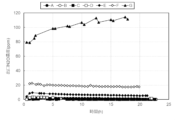
- FIG. 3 is a diagram showing the change in NH 3 concentration at the outlet of a reactor at 550°C.
- FIG. 2 is a diagram showing the change in NOx concentration at the outlet of a reactor at 550°C. It is a figure showing the transition of N 2 O concentration at the reactor outlet at 550°C.
- FIG. 3 is a diagram comparing the NH 3 concentration at the reactor outlet at 550°C.
- FIG. 3 is a diagram comparing the NOx concentration at the reactor outlet at 550°C.
- FIG. 2 is a diagram comparing the N 2 O concentration at the reactor outlet at 550°C.
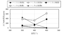
- FIG. 3 is a diagram showing the temperature dependence of NOX decomposition rate (removal rate).
- FIG. 2 is a diagram showing the temperature dependence of N 2 O concentration at the reactor outlet. It is a figure comparing NH3 decomposition rate.
- FIG. 3 is a diagram comparing denitrification rates.
- FIG. 3 is a diagram comparing the N 2 O concentration at the reactor outlet.
- FIG. 2 is a diagram showing an example of an apparatus for detoxifying high-temperature NH 3 -containing gas.
- FIG. 2 is a diagram showing an example of a device for detoxifying low-temperature NH 3 -containing gas.
- FIG. 2 is a diagram showing an example of an apparatus for detoxifying high-temperature NH 3 -containing gas.
- FIG. 2 is a diagram showing an example of an apparatus for detoxifying high-temperature NH 3 -containing gas.
- FIG. 2 is a diagram showing an example of an apparatus for detoxifying high-temperature NH 3 -containing gas.
- the catalyst of the present invention is a catalyst for promoting the decomposition reaction of ammonia.
- the catalyst of the present invention includes a mixture of a first catalyst powder and a second catalyst powder, or a mixture of a first catalyst powder, a second catalyst powder, and a third catalyst powder.
- the first catalyst powder contains a carrier and a noble metal.
- the carrier is a carrier containing at least one selected from the group consisting of ceria, silica, alumina, titania, zirconia, and zeolite.
- a carrier containing silica and/or titania is preferably used.
- the carrier is porous.
- the specific surface area of the carrier is not particularly limited, and is preferably, for example, 10 to 1,000 m 2 /g, more preferably 100 to 500 m 2 /g.
- the carrier include: ceria powder, silica powder, alumina powder, titania powder, zirconia powder, or zeolite powder; two or more selected from the group consisting of ceria powder, silica powder, alumina powder, titania powder, zirconia powder, and zeolite powder.
- a mixture of powders of two or more selected from the group consisting of ceria, silica, alumina, titania, zirconia and zeolite for example, silica titania, alumina titania, ceria titania, silica alumina, silica zirconia, alumina zirconia, etc.
- Powder at least one powder selected from the group consisting of ceria powder, silica powder, alumina powder, titania powder, zirconia powder, and zeolite powder, and the above powder selected from the group consisting of cerium, silicon, aluminum, titanium, and zirconium; Examples include powders doped, supported, or composited with at least one element different from the elements constituting the powder and/or other mundane metal elements such as molybdenum, tungsten, and vanadium. Doped, supported or composited powders tend to be more resistant to hydrothermal aging.
- the noble metal is at least one selected from the group consisting of gold, silver, platinum, ruthenium, rhodium, palladium, osmium, iridium, and rhenium.
- platinum and/or iridium are particularly preferably used.
- a noble metal is supported on a carrier.
- the ratio of the noble metal to the carrier in the first catalyst powder is preferably 0.01 to 10% by mass, more preferably 0.02 to 5% by mass, and even more preferably 0.05 to 2% by mass.
- a metal element other than the noble metal may be supported on the carrier.
- other metal elements include rare earth elements such as cerium (Ce), and mundane metal elements such as molybdenum, tungsten, and vanadium.
- the ratio of the rare earth element to the carrier in the first catalyst powder is not particularly limited as long as it does not impede the effects of the present invention.
- the ratio of the mass of the rare earth element to the mass of the noble metal in the first catalyst powder is preferably 1 or more and less than 10, more preferably 3 or more and 7 or less, and even more preferably 4 or more and 6 or less.
- the first catalyst powder formed by supporting a metal element other than a noble metal on a carrier tends to have high resistance to hydrothermal aging.
- Preparation of the first catalyst powder includes, for example, supporting the noble metal on a carrier, and then crushing or crushing it as necessary to powder it. Supporting can be carried out, for example, by immersing the carrier in a solution, suspension, or emulsion containing the noble metal. Supporting of metal elements other than noble metals can also be carried out in the same manner. After soaking, kneading, evaporation to dryness, drying, calcination, etc. can be performed. The temperature during drying may be any temperature that can remove the liquid, and is, for example, 100 to 150°C. The temperature during firing may be lower than the heat resistance temperature of the carrier, for example, 350 to 550°C. The firing time is, for example, 1 to 5 hours.
- the first catalyst powder is preferably porous.
- the pore size distribution of the first catalyst powder is not particularly limited.
- the first catalyst powder is not particularly limited by the particle size distribution, as long as it forms a fine powder. Particle size distribution can be adjusted by grinding/disintegration, classification, etc.
- the second catalyst powder contains zeolite and metal ions that can be ion-exchanged with it.
- Zeolites include, for example, amiciite, analcime, barrerite, bellbergite, bikitaite, boggsite, brewsterite, and strontium.
- Brewsterite-Sr heavy earth Brewsterite-Ba, chabazite, chabazite-Ca, chabazite-Na, chabazite-Na K), chiavennite, clinoptilolite, potash clinoptilolite-K, clinoptilolite-Na, clinoptilolite-Ca, cowlesite ), dachiardite, dachiardite-Ca, dachiardite-Na, edingtonite, epistilbite, erionite, erionite -Na), erionite-K, erionite-Ca, faujasite, faujasite-Na, faujasite-Ca, magnesium faujasite-Mg,
- Natural zeolites A type (LTA type) zeolite, X type (FAU type) zeolite, LSX type (FAU type) zeolite, Beta type (BEA type) zeolite, ZSM-5 type (MFI type) zeolite, Ferrierite type (FER type) zeolite, mordenite type (MOR type) zeolite, L type (LTL type) zeolite, Y type (FAU type) zeolite, MCM-22 type (MWW type) zeolite, offretite/erionite type (O/E type) Zeolite, AEI type zeolite, AEL type zeolite, AFT type zeolite, AFX type zeolite, CHA type zeolite, EAB type zeolite, ERI type zeolite, KFI type zeolite, LEV type zeolite, LTN type zeolite, MSO type zeolite, RHO type zeolite
- the ratio of SiO 2 to Al 2 O 3 (SiO 2 /Al 2 O 3 ratio) in the zeolite is preferably 5 to 100, more preferably 7 to 50, and still more preferably 9 to 30.
- the higher the proportion of SiO 2 the higher the durability of the catalyst tends to be.
- the higher the proportion of Al 2 O 3 the more the amount of metal ions that can be exchanged increases, so the SiO 2 /Al 2 O 3 ratio has an optimal value.
- the zeolite is porous.
- the pore diameter of the zeolite is not particularly limited, and is preferably, for example, 0.01 to 10 nm, more preferably 0.2 to 2 nm.
- Synthetic zeolite is produced by, for example, mixing a silica source, an alumina source, an alkali source, a solvent, an organic structure-directing agent (OSDA), a surfactant, etc. to obtain a starting reaction mixture, which is then heated in an autoclave. It can be obtained through a hydrothermal reaction at high temperature and pressure.
- the synthetic zeolite obtained by this method contains organic components derived from OSDA. However, it appears that the organic content can be removed by subsequent firing.
- Certain synthetic zeolites can be obtained by hydrothermal reaction without the use of OSDA. Furthermore, certain synthetic zeolites can be obtained without the use of OSDA using mechanochemical processing and steam synthesis methods.
- Synthetic zeolite obtained without using OSDA (hereinafter sometimes referred to as OSDA-free zeolite) does not contain organic components derived from OSDA.
- OSDA-free zeolite can be preferably used.
- the SiO 2 /Al 2 O 3 molar ratio in the OSDA free zeolite is preferably 1 or more, more preferably 5 or more, and still more preferably 8 or more.
- the upper limit of the SiO 2 /Al 2 O 3 molar ratio in the OSDA free zeolite is, for example, preferably 50, more preferably 45, and even more preferably 40.
- the ion-exchangeable metal ion is preferably at least one ion selected from the group consisting of Fe ions, Ce ions, Co ions, and Cu ions, and more preferably Fe ions.
- the second catalyst powder is obtained by exchanging (ion exchange) the cations of the elements constituting the zeolite with Fe, Ce, Co, or Cu cations.
- the second catalyst powder may include zeolite to which at least one selected from the group consisting of Fe, Ce, Co, and Cu is attached (supported).
- the ratio of ion-exchangeable metal ions to zeolite in the second catalyst powder is preferably 0.1 to 10% by mass, more preferably 0.7 to 7% by mass.
- the proportion of Fe ions to zeolite is preferably 0.1 to 10% by weight, more preferably 0.7 to 7% by weight.
- Ion exchange can be performed by immersing the zeolite in a liquid containing ion-exchangeable metal ions, and then filtering/drying/calcining as necessary. It is preferable to adjust the pH of the liquid containing ion-exchangeable metal ions in which the zeolite is immersed.
- the pH of the liquid containing ion-exchangeable metal ions is, for example, 1 to 8, preferably 3.5 to 7.5, more preferably 5.5 to 7.0.
- basic compounds such as sodium hydroxide, potassium hydroxide, rubidium hydroxide, cesium hydroxide, sodium carbonate, potassium carbonate, etc., or acidic compounds such as hydrochloric acid, nitric acid, etc. can be used.
- the temperature during drying may be any temperature that can remove the liquid, and is, for example, 100 to 150°C.
- the temperature during firing may be lower than the heat-resistant temperature of zeolite, for example, 350 to 800°C.
- the firing time can be appropriately set depending on the temperature during firing, and is, for example, 1 to 10 hours. After ion exchange, it can be pulverized by crushing or crushing, if necessary.
- the second catalyst powder is preferably porous.
- the pore size distribution of the second catalyst powder is not particularly limited.
- the second catalyst powder is not particularly limited by the particle size distribution, as long as it forms a fine powder. Particle size distribution can be adjusted by grinding/disintegration, classification, etc.
- the second catalyst powder has acid sites derived from OH groups and the like.
- the properties of acid sites can generally be observed by a method known as the pyridine-TPD method.
- a flame ionization detector FID
- Pyridine is adsorbed at the acid site. Pyridine can be adsorbed to acid sites on the outer surface of the pores and acid sites on the inner surface of the pores of the catalyst. It is generally understood that the higher the temperature at which adsorbed pyridine is desorbed, the stronger the acid strength of the acid site.
- the pyridine that is desorbed at high temperatures comes from acid sites that are affected by diffusion, that is, acid sites located on the inner surface of the pores (Nakano et al. Acid Property Measurement” Toyo Soda Research Report Vol. 29 No. 1 (1985), pp3-11).
- the effective molecular diameter of pyridine is said to be 5.8 ⁇ (see Anderson et al. J. Catal., 58, 114 (1979)).
- the total amount of acid sites can be determined based on the saturated adsorption amount of pyridine.
- pyridine adsorption can be carried out at room temperature to 150°C, preferably at 150°C.
- the ratio of the total amount of pyridine desorbed within the range of 150° C. or more and less than 450° C. to the total amount of pyridine desorbed within the range of 450° C. or more and 800° C. or less is preferably 0. .9 or more, more preferably 0.98 or more, still more preferably 1 or more, even more preferably 1.1 or more.
- the upper limit of the ratio of the total amount of pyridine desorbed within the range of 150° C. or more and less than 450° C. to the total amount of pyridine desorbed within the range of 450° C. or more and 800° C. or less is not particularly limited as long as it can be manufactured.
- the total amount of pyridine desorbed within the range of 150°C or more and less than 450°C is preferably 100 ⁇ mol or more, more preferably 200 ⁇ mol or more, and even more preferably 250 ⁇ mol or more per 1 g of catalyst. , more preferably 300 ⁇ mol or more.
- the upper limit of the total amount of pyridine that is eliminated within the range of 150° C. or more and less than 450° C. is not particularly limited as long as it can be produced.
- the total amount of pyridine desorbed within the range of 450°C to 800°C is preferably 1000 ⁇ mol or less, more preferably 800 ⁇ mol or less, and even more preferably 500 ⁇ mol or less, per 1 g of catalyst. It is.
- the lower limit of the total amount of pyridine that is eliminated within the range of 450° C. or higher and 800° C. or lower is not particularly limited as long as it can be produced.
- the value of the L peak (the amount of pyridine eliminated at the top of the maximum peak in the range of 150°C or more and less than 450°C) is different from the value of the H peak (the amount of pyridine eliminated at the top of the maximum peak in the range of 450°C or more and less than 800°C). (the amount of pyridine eliminated at the top of the maximum peak within the range). That is, the ratio of the L peak value to the H peak value is preferably more than 1, more preferably 1.12 or more, even more preferably 1.2 or more, even more preferably 1.4 or more, and most preferably 1. It is 6 or more.
- the upper limit of the ratio of the L peak value to the H peak value is not particularly limited as long as it can be manufactured.
- the second catalyst powder has a lower limit of the temperature at which the H peak appears (the temperature at the top of the maximum peak in the range of 450°C or more and 800°C or less) in the TPD spectrum, preferably 490°C, more preferably 510°C, More preferably, it is 530°C, and the upper limit is 650°C, more preferably 620°C, still more preferably 600°C, even more preferably 580°C.
- the second catalyst powder is preferably one that has a large amount of saturated adsorption of pyridine.
- the saturated adsorption amount of pyridine in the second catalyst powder is preferably 100 ⁇ mol or more, more preferably 200 ⁇ mol or more, still more preferably 500 ⁇ mol or more, even more preferably 700 ⁇ mol or more, per 1 g of catalyst.
- the upper limit of the saturated adsorption amount of pyridine in the second catalyst powder is not particularly limited as long as it can be produced, and is, for example, preferably 2000 ⁇ mol, more preferably 1500 ⁇ mol, per 1 g of catalyst.
- the saturated adsorption amount of pyridine can be measured at 150°C.
- the second catalyst powder preferably has a large crystallite size.
- the crystallite size in the second catalyst powder is preferably 5 nm or more, more preferably 10 nm or more, even more preferably 20 nm or more, even more preferably 30 nm or more.
- the upper limit of the crystallite size of the second catalyst powder is not particularly limited as long as it can be manufactured, and is, for example, preferably 100 nm, more preferably 80 nm.
- the crystallite size can be measured by an X-ray diffraction method (see, for example, JIS H 7805 or JIS R 7651).
- the second catalyst powder preferably has a high NO 2 decomposition rate and a high NO decomposition rate even after being exposed to a gas at 530° C. containing 20% H 2 O and 20 ppm SO 2 for 70 hours. Even after the second catalyst powder was exposed to a gas at 530°C containing 20% H 2 O and 20 ppm SO 2 for 70 hours, the NO 2 decomposition rate was 60% or more and the NO decomposition rate was 90% at 450°C. The above is preferable.
- the third catalyst powder comprises an oxide of titanium, an oxide of tungsten and/or molybdenum, and an oxide of cerium and/or vanadium, preferably an oxide of titanium, an oxide of tungsten, and an oxide of cerium. It contains an oxide.
- the ratio of Ce element and/or V element to Ti element is preferably 1 to 20% by weight, more preferably 3 to 15% by weight as a weight percentage of (CeO 2 +V 2 O 5 )/TiO 2 .
- the ratio of the Mo element and/or the W element to the Ti element is preferably 1 to 50% by weight, more preferably 10 to 40% by weight as a weight percentage of (MoO 3 +WO 3 )/TiO 2 .
- titanium oxide powder or a titanium oxide precursor can be used as a raw material for the titanium oxide.
- the titanium oxide precursor include titanium oxide slurry, titanium oxide sol; titanium sulfate, titanium tetrachloride, titanate, and titanium alkoxide.
- a material that forms anatase-type titanium oxide is preferably used as the raw material for the titanium oxide.
- vanadium compounds such as vanadium pentoxide, ammonium metavanadate, vanadyl sulfate, etc. can be used.
- tungsten oxide As a raw material for the tungsten oxide, ammonium paratungstate, ammonium metatungstate, tungsten trioxide, tungsten chloride, etc. can be used. Ammonium molybdate, molybdenum trioxide, etc. can be used as a raw material for molybdenum oxide.
- cerium oxide ceric nitrate, ceric nitrate, cerium carbonate, ceric sulfate, ceric sulfate, ceric acetate, etc. can be used.
- the third catalyst powder contains P oxide, S oxide, Al oxide (e.g. alumina), Si oxide (e.g. glass fiber), Zr oxide ( For example, zirconia), gypsum (for example, dihydrate gypsum, etc.), zeolite, etc. may be included. These can be used in the preparation of catalysts in the form of powder, sol, slurry, fiber, etc.
- the third catalyst powder can be prepared by, for example, adding a solvent (e.g., water) to each oxide raw material and, if necessary, a co-catalyst or additive, kneading the mixture, evaporating the resulting kneaded product to dryness, This includes drying, firing, and then, if necessary, crushing or crushing and powdering.
- a solvent e.g., water
- the temperature during drying may be any temperature that can remove the liquid, and is, for example, 100 to 150°C.
- the temperature during firing may be lower than the heat-resistant temperature of the oxide, for example, 350 to 550°C.
- the firing time is, for example, 1 to 5 hours.
- the third catalyst powder is preferably porous.
- the pore size distribution of the third catalyst powder is not particularly limited.
- the third catalyst powder is not particularly limited by the particle size distribution, as long as it forms a fine powder. Particle size distribution can be adjusted by grinding/disintegration, classification, etc.
- the catalyst of the present invention can be obtained by mixing a first catalyst powder and a second catalyst powder, or by mixing a first catalyst powder, a second catalyst powder, and a third catalyst powder.
- the mixing may be dry mixing or wet mixing. After mixing, drying or baking, crushing/crushing, granulation, and classification can be performed as necessary.
- the temperature during drying may be any temperature that can remove the liquid, and is, for example, 100 to 150°C.
- the temperature during firing may be lower than the heat-resistant temperature of the oxide, and is, for example, preferably 350 to 650°C, more preferably 450 to 600°C, and even more preferably 480 to 570°C.
- the firing time can be appropriately set depending on the temperature during firing, and is, for example, 1 to 5 hours.
- the catalyst of the present invention is not particularly limited by particle size distribution. Particle size distribution can be adjusted by grinding/disintegration, granulation, classification, etc.
- the mixing ratio of the first catalyst powder and the second catalyst powder or the mixing ratio of the first catalyst powder, the second catalyst powder, and the third catalyst powder are, for example, the NH 3 concentration, NO
- the X concentration and the N 2 O concentration can each be set within predetermined ranges.
- the amount of the first catalyst powder contained in the catalyst of the present invention is preferably 0.01 to 10% by weight, more preferably 0.1 to 5% by weight, and even more preferably 0.5 to 3% by weight.
- the amount of noble metal contained in the catalyst of the present invention is preferably 0.05 to 1000 ppm, more preferably 0.1 to 500 ppm, and still more preferably 5 to 200 ppm.
- the amount of the second catalyst powder per 1 part by mass of the first catalyst powder is preferably 1 to 100 parts by mass, more preferably 10 to 70 parts by mass, and even more preferably 20 to 55 parts by mass.
- the third catalyst powder can be mixed when heat resistance is required.
- the third catalyst powder is preferably used in an amount of 0 to 70 parts by weight, more preferably 0 to 50 parts by weight, and even more preferably 0 to 30 parts by weight per 1 part by weight of the first catalyst powder. As the proportion of the third catalyst powder increases, the NH 3 outlet concentration can be lowered in the reaction at high temperatures such as 500° C. or higher.
- the catalyst of the present invention may be made into a catalyst by adhering (supporting) the mixture to a support, or may be made by molding the mixture.
- the support include a honeycomb support; a corrugated support; and a plate-like support (lath board) such as expanded metal and perforated metal (punched metal).
- the amount of the catalyst attached to the support can be determined as appropriate, taking into account improvement in catalyst filling rate and the like.
- the mixture is made of honeycomb, corrugate, cone, truncated cone, ellipsoid, spindle, RASCHIG RING, DIXSON, saddle, etc. in order to improve the catalyst loading rate and suppress the increase in head loss. It can be molded into shapes such as Mc MAHON.
- the temperature during drying may be any temperature that can remove the liquid, and is, for example, 100 to 150°C.
- the temperature during firing may be lower than the heat-resistant temperature of the oxide, and is, for example, preferably 350 to 650°C, more preferably 450 to 600°C, and even more preferably 480 to 570°C.
- the firing time can be appropriately set depending on the temperature during firing, and is, for example, 1 to 5 hours.
- the method of the present invention is a method for rendering a gas to be treated harmless.
- the gas to be treated means the gas flowing into the catalyst layer (where the catalyst of the present invention is present) or the gas passing through the catalyst layer.
- the gas to be treated includes not only the gas flowing into or passing through the former catalyst layer, but also the gas flowing into the latter catalyst layer or passing through the latter catalyst layer. It also implies gases that are
- the gas to be treated is a gas containing NH 3 and O 2 .
- the NH 3 -containing gas can be used as it is as the gas to be treated; if not, the NH 3 -containing gas and the O 2 -containing gas are mixed.
- the gas obtained by this can be used as the gas to be processed.
- the NH 3 -containing gas include exhaust gas generated by combustion of ammonia fuel, exhaust gas released during purging of ammonia-related equipment, or exhaust gas released during treatment of ammonia-containing wastewater.
- NH3 - containing gas such as ammonia fuel ships, ammonia transport ships, ammonia fuel storage bases, ammonia tanks for denitrification equipment in power plants, ammonia cooling and freezing equipment, and food and drinking water production.
- Gas discharged from fields that treat ammonia-containing wastewater such as wastewater, chemical factory wastewater, plating wastewater, semiconductor component manufacturing wastewater, and domestic wastewater can be used.
- NH 3 When NH 3 is dissolved in a liquid, or when NH 3 is adsorbed on a solid, it can be vaporized using a stripping tower, a vaporizer, or the like.
- the atmosphere can be used as the O 2 -containing gas.
- the mass ratio of O 2 to NH 3 and the temperature of the gas to be treated are determined such that, for example, the NH 3 concentration , NO can be set to .
- Temperature adjustment can be performed by a known method, for example, using a temperature adjustment device such as a heater, a heat exchanger, or a cooler.
- the gas flowing out from the catalyst layer may be used as the heat transfer medium used to adjust the temperature of the gas to be treated.
- the exhaust gas produced by combustion of ammonia fuel contains NOx and/or N2O .
- the gas to be treated may further contain NOx and/or N2O .
- the method of the present invention involves a chemical reaction in which NH3 contained in the gas to be treated is converted into nitrogen and water, and NOX and N2O contained in the gas to be treated are converted into nitrogen and water in the presence of the catalyst of the present invention. It involves carrying out a chemical reaction. NO X and N 2 O may be originally contained in the gas flowing into the catalyst layer, or may be generated while passing through the catalyst layer.
- the chemical reaction is carried out in a continuous flow reactor.
- a catalyst layer inside the reactor.
- gas adjusted to a predetermined temperature is allowed to flow in from the reactor inlet
- a chemical reaction is carried out in a catalyst layer within the reactor
- the gas is allowed to flow out from the reactor outlet.
- the catalyst of the present invention can be installed in the reactor in the form of a fixed bed, fluidized bed, moving bed, simulated moving bed, etc., preferably in the form of a fixed bed or a simulated moving bed.
- the temperature of the gas at the inlet of the reactor is, for example, preferably 300 to 600°C, more preferably 350 to 550°C.
- the method of the present invention includes adding at least one reaction aid selected from the group consisting of ammonia and urea to the gas to be treated.
- urea decomposes into carbon dioxide and ammonia by an endothermic reaction.
- Addition of the reaction aid is preferably carried out when the amount of NO X and N 2 O contained in the gas to be treated is large.
- the method of the present invention further includes cooling the gas to be treated.
- Gas discharged from combustion devices such as furnaces and internal combustion engines is often at a high temperature.
- the inflow of the high temperature gas to be treated increases the temperature of the catalyst layer.
- An excessive temperature rise in the catalyst layer increases the risk of catalyst deterioration.
- If the temperature of the gas to be treated is too high, it is preferable to cool the gas to be treated to prevent deterioration of the catalyst.
- the gas to be treated can be cooled by adding low-temperature gas such as the atmosphere to the gas to be treated, by exchanging heat between the gas to be treated and a refrigerant, or the like.
- the method of the present invention may further include adjusting the amount of reaction aid added to the treated gas based on the temperature of the treated gas and the amount of NOx and N2O contained in the treated gas. preferable.
- the method of the present invention further includes adjusting the degree of cooling of the gas to be treated based on the temperature of the treated gas.
- the temperature of the treated gas is a substitute value for the temperature of the catalyst layer.
- the temperature of the treated gas is preferably measured near the outlet of the catalyst layer and near the outlet of the reactor. If the temperature of the catalyst layer can be directly measured, that temperature may be used.
- treated gas means gas that has flowed out from the catalyst layer (where the catalyst of the present invention is present).
- the treated gas includes not only the gas that has flowed out from the front catalyst layer but also the gas that has flowed out from the rear catalyst layer.
- the gas to be treated to which the reaction auxiliary agent is added or cooled is placed before the treated gas whose temperature etc. are measured.
- it is a gas to be treated.
- the amount of addition of the reaction aid and the degree of cooling of the gas to be treated can be adjusted by considering the following points, for example.
- the direct decomposition reaction of ammonia is an exothermic reaction. If more ammonia is used in the direct decomposition reaction, the temperature of the catalyst bed will increase, and the temperature of the treated gas will increase. That is, addition of reaction aids may increase the temperature of the treated gas. Furthermore, the inflow of the high-temperature gas to be treated increases the temperature of the catalyst layer. As the temperature of the catalyst layer increases, the rates of the direct decomposition reaction of ammonia and the decomposition reaction of N 2 O tend to increase. However, the higher the temperature of the catalyst layer, the greater the risk of deterioration of the catalyst.
- the direct decomposition reaction of ammonia, the decomposition reaction of NOx , and the decomposition reaction of N2O reduce ammonia in the gas to be treated.
- ammonia is reduced, the decomposition reaction of NO X and the decomposition reaction of N 2 O become difficult to proceed, and the amount of NO X or N 2 O in the treated gas may increase.
- the temperature of the treated gas in each stage is, for example, preferably 400 to 600°C, more preferably 450 to 550°C.
- the concentration of NO X in the treated gas at the final stage is, for example, preferably 500 ppm or less, more preferably 200 ppm or less.
- the concentration of N 2 O in the final stage treated gas is, for example, preferably 100 ppm or less, more preferably 10 ppm or less.
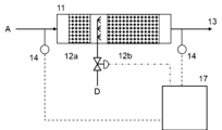
- the apparatus shown in FIG. 14 for making a gas to be treated harmless includes a reactor 11 and a catalyst layer 12.
- the apparatus shown in FIG. 14 can be suitably used to treat high temperature NH 3 -containing gas such as NH 3 fuel combustion exhaust gas.
- the apparatus shown in FIG. 15 for making a gas to be treated harmless includes a temperature adjustment mechanism, a reactor 11, a catalyst layer 12, and a control device 17.
- the temperature adjustment mechanism in the apparatus shown in FIG. 15 is configured to be able to raise the temperature of the gas to be processed to a predetermined temperature.
- a heat exchanger 9 is configured to perform heat exchange between the gas to be treated and the treated gas, and a heat exchanger 9 is configured to perform heat exchange between the gas to be treated and an external heat source.
- a heated heater 10h is provided.
- the apparatus shown in FIG. 15 can be suitably used for processing low-temperature NH 3 -containing gas such as purge gas for NH 3 -related equipment.
- a gas to be treated can be obtained by mixing NH 3 -containing gas A and O 2 -containing gas B in a mixer 5.
- the respective supply amounts of NH 3 -containing gas A and O 2 -containing gas B can be adjusted by the opening degree of each control valve.
- the amount of treated gas supplied to the heat exchanger 9 can be adjusted by the opening degree of the control valve installed in the heat exchanger bypass pipe 3, and thereby the amount of heat exchanged in the heat exchanger 9 can be adjusted. If the temperature of the gas to be treated can be controlled, there is no need to provide the heat exchanger 9 and/or the heater 10h.
- the catalyst layer 12 is made of the catalyst or catalyst body of the present invention, and is fixed within the reactor 11.
- the amount of inflow of the gas to be treated into the catalyst layer can also be adjusted by the opening degree of the control valve installed in the catalyst layer inflow pipe 2.
- the amount of the gas to be treated flowing in through the catalyst layer inlet pipe 2 is preferably kept substantially constant in order to stably perform the chemical reaction in the catalyst layer 12.
- the measurement mechanism measures physical property values necessary for monitoring the operating state of the device.
- a plurality of measuring devices 14 measure the gas temperature in the mixer; the gas temperature on the inlet side of the catalyst layer, the NH 3 concentration, the O 2 concentration, the NO X concentration, the N 2 O concentration, etc.; It is configured to be able to measure gas temperature, NH 3 concentration, O 2 concentration, NO X concentration, N 2 O concentration, etc. on the outlet side. Based on the measured values by the measurement mechanism, the amount of NH3 - containing gas A supplied , the amount of O2- containing gas B supplied, the amount of gas to be treated flowing into the catalyst layer, the temperature of the gas to be treated flowing into the catalyst layer, etc.
- control device 17 It is configured so that it can be controlled.
- the goal of the control in the control device 17 is, for example, to avoid high temperature conditions such as hot spots in the catalyst layer and to reduce the amount of N 2 O, NO X and/or NH 3 contained in the exhaust gas 13 .
- the apparatus shown in FIG. 16 for making a gas to be treated harmless includes a reactor 11, a catalyst layer 12, and a control device 17.
- the apparatus shown in FIG. 16 can be suitably used to treat high temperature NH 3 -containing gas such as NH 3 fuel combustion exhaust gas.
- the amount of reaction aid C supplied can be adjusted by the opening degree of the control valve.
- the measurement mechanism measures physical property values necessary for monitoring the operating state of the device.
- a plurality of measuring instruments 14 measure the gas temperature of the mixer; the gas temperature at the inlet side of the catalyst layer, the NH 3 concentration, the O 2 concentration, the NO X concentration, the N 2 O concentration, etc.; It is configured to be able to measure gas temperature, NH 3 concentration, O 2 concentration, NO X concentration, N 2 O concentration, etc. on the outlet side.
- the structure is such that the supply amount of the reaction aid C, etc. can be controlled based on the measured value by the measurement mechanism.
- the goal of the control in the control device 17 is, for example, to avoid high temperature conditions such as hot spots in the catalyst layer and to reduce the amount of N 2 O, NO X and/or NH 3 contained in the exhaust gas 13 .
- the configuration is the same as that of the device shown in FIG.
- the apparatus shown in FIG. 17 for making a gas to be treated harmless includes a temperature adjustment mechanism, a reactor 11, a catalyst layer 12, and a control device 17.
- the temperature adjustment mechanism in the apparatus shown in FIG. 17 is configured to be able to lower the temperature of the gas to be processed to a predetermined temperature.
- the apparatus shown in FIG. 17 is provided with a cooling air supply device for lowering the temperature of the gas to be processed.
- the apparatus shown in FIG. 17 can be suitably used to treat high temperature NH 3 -containing gas such as exhaust gas from a combustion device. Supplying air having a temperature lower than that of the gas to be processed has the effect of lowering the temperature of the gas to be processed. Even if a cooler configured to exchange heat with an external cold source is provided, the same effect as the supply of cooling air can be obtained.
- the configuration is the same as that of the device shown in FIG.
- the apparatus shown in FIG. 18 for making a gas to be treated harmless includes a temperature adjustment mechanism, a reactor 11, catalyst layers 12a and 12b, and a control device 17.
- the temperature adjustment mechanism in the apparatus shown in FIG. 18 is configured to be able to lower the temperature of the gas flowing out from the catalyst layer 12a to a predetermined temperature before flowing into the catalyst layer 12b.
- the apparatus shown in FIG. 18 is provided with a cooler configured to supply cooling air to lower the temperature of the gas flowing out from the catalyst layer 12a.
- the apparatus shown in FIG. 18 can be suitably used to treat high temperature NH 3 -containing gas such as exhaust gas from a combustion device. Even if a cooler configured to exchange heat with an external cold source is provided, the same effect as the supply of cooling air can be obtained.
- the configuration is the same as that of the device shown in FIG.
- Example 1 Honeycomb catalyst body A (Preparation of first catalyst powder (1)) 100 g of amorphous silica powder was added to an aqueous solution of chloroplatinic acid hexahydrate (H 2 PtCl 6.6H 2 O), stirred, and then evaporated to dryness on a sand bath. The dried product was calcined in air at 500° C. for 2 hours. The obtained calcined product was pulverized to obtain a first catalyst powder (1) in which 0.05% by mass of platinum was supported on amorphous silica powder.
- chloroplatinic acid hexahydrate H 2 PtCl 6.6H 2 O
- the dried cake was placed in a furnace, the temperature was raised at 100°C/h, and the cake was baked at 500°C for 5 hours.
- the calcined product was pulverized to obtain a second catalyst powder (1) in which Fe ions were ion-exchanged with zeolite.
- Example 2 Honeycomb catalyst body B] 2 parts by mass of first catalyst powder (1), 78 parts by mass of second catalyst powder (1) and 20 parts by mass of third catalyst powder, 2 parts by mass of first catalyst powder (1) and 88 parts by mass of second catalyst powder (1)
- a honeycomb catalyst body B was obtained in the same manner as in Example 1 except that the third catalyst powder was changed to 10 parts by mass.
- the NH 3 concentration , NO The results are shown in Figures 1-6.
- Example 3 Honeycomb catalyst body C] 2 parts by mass of first catalyst powder (1), 78 parts by mass of second catalyst powder (1) and 20 parts by mass of third catalyst powder, 2 parts by mass of first catalyst powder (1) and 98 parts by mass of second catalyst powder (1)
- a honeycomb catalyst body C was obtained in the same manner as in Example 1 except that the amount was changed.
- the NH 3 concentration , NO The results are shown in Figures 1-6.
- Example 4 Honeycomb catalyst body D] 2 parts by mass of first catalyst powder (1), 78 parts by mass of second catalyst powder (1), 20 parts by mass of third catalyst powder, 2 parts by mass of first catalyst powder (1) and 70 parts by mass of second catalyst powder (1)
- a honeycomb catalyst body D was obtained in the same manner as in Example 1 except that the third catalyst powder was changed to 28 parts by mass.
- the NH 3 concentration , NO The results are shown in Figures 1-6.
- Example 5 Honeycomb catalyst body E] 2 parts by mass of first catalyst powder (1), 78 parts by mass of second catalyst powder (1), 20 parts by mass of third catalyst powder, 2 parts by mass of first catalyst powder (1) and 50 parts by mass of second catalyst powder (1)
- a honeycomb catalyst body E was obtained in the same manner as in Example 1 except that the third catalyst powder was changed to 48 parts by mass.
- the NH 3 concentration , NO The results are shown in Figures 1-6.
- Example 6 Honeycomb catalyst body F] 2 parts by mass of first catalyst powder (1), 78 parts by mass of second catalyst powder (1), 20 parts by mass of third catalyst powder, 2 parts by mass of first catalyst powder (1) and 30 parts by mass of second catalyst powder (1)
- a honeycomb catalyst body F was obtained in the same manner as in Example 1 except that the third catalyst powder was changed to 68 parts by mass.
- the NH 3 concentration , NO The results are shown in Figures 1-6.
- Example 7 Honeycomb catalyst body G
- 2 parts by mass of first catalyst powder (1), 78 parts by mass of second catalyst powder (1) and 20 parts by mass of third catalyst powder were changed to 2 parts by mass of first catalyst powder (1) and 98 parts by mass of third catalyst powder.
- Honeycomb catalyst body G was obtained in the same manner as in Example 1 except for the following.
- the NH 3 concentration , NO The results are shown in Figures 1-6.
- the honeycomb catalyst body using the catalyst of the present invention can decompose NH3 with high efficiency (approximately 97% or more) even at high temperatures of 500°C or higher, and in particular, the honeycomb catalyst bodies A, B, C and D can decompose NH 3 and remove NO X and N 2 O with high efficiency.
- Example 8 Honeycomb catalyst body C
- Manufacture of catalyst 2 parts by mass of the first catalyst powder (1) and 98 parts by mass of the second catalyst powder (1) were added to pure water to obtain a slurry.
- This slurry was applied to a honeycomb substrate at a coverage of 140 g/m 2 . This was dried at 120°C for 2 hours.
- the honeycomb catalyst body C was obtained by firing at 500° C. for 2 hours.
- the amount of platinum contained in the catalyst of honeycomb catalyst body C was 10 ppm.
- Example 9 Honeycomb catalyst body H
- Example 8 except that 2 parts by mass of the first catalyst powder (1) and 98 parts by mass of the second catalyst powder (1) were changed to 4 parts by mass of the first catalyst powder (1) and 96 parts by mass of the second catalyst powder (1).
- Honeycomb catalyst body H was obtained in the same manner.
- the amount of platinum contained in the catalyst of honeycomb catalyst body H was 20 ppm.
- the NH 3 concentration , NO The NH3 decomposition rate and NOX decomposition rate (removal rate) were calculated. The results are shown in Figures 7-13.
- Example 10 Honeycomb catalyst body I (Preparation of NOX reduction catalyst powder) Mix 715 g of anatase-type titanium oxide powder with a surface area of 300 m 2 /g or more, 385 g of anatase-type titanium oxide powder with a specific surface area of 90 m 2 /g or less, 194 g of ammonium metatungstate, 80 g of ammonium metavanadate, 103 g of oxalic acid, and 560 g of water to make a paste. I made it. The resulting paste was granulated. The granules were dried at 120°C for 4 hours and then calcined at 500°C for 2 hours. The obtained calcined product was pulverized to obtain NO X reduction catalyst powder.
- Example 8 Same as Example 8 except that 2 parts by mass of first catalyst powder (1) and 98 parts by mass of second catalyst powder (1) were changed to 1 part by mass of first catalyst powder (1) and 99 parts by mass of NOx reduction catalyst powder.
- a honeycomb catalyst body I was obtained by the method. The amount of platinum contained in the catalyst of honeycomb catalyst body I was 5 ppm. The NH 3 concentration , NO The NH3 decomposition rate and NOX decomposition rate (removal rate) were calculated. The results are shown in Figures 7-13.
- Example 11 Honeycomb catalyst body J
- a honeycomb catalyst body J was obtained by the method.
- the amount of platinum contained in the catalyst of honeycomb catalyst body J was 20 ppm.
- the NH 3 concentration , NO The NH3 decomposition rate and NOX decomposition rate (removal rate) were calculated. The results are shown in Figures 7-13.
- Example 12 Honeycomb catalyst body K
- the NH 3 concentration , NO The NH3 decomposition rate and NOX decomposition rate (removal rate) were calculated. The results are shown in Figures 7-13.
- Example 13 Honeycomb catalyst body L
- the dried cake was placed in a furnace, the temperature was raised at 100°C/h, and the cake was baked at 500°C for 5 hours.
- the calcined product was pulverized to obtain N 2 O decomposition catalyst powder in which Cu ions were ion-exchanged with zeolite.
- Example 8 Same as Example 8 except that 2 parts by mass of the first catalyst powder (1) and 98 parts by mass of the second catalyst powder (1) were changed to 2 parts by mass of the first catalyst powder (1) and 98 parts by mass of the N 2 O decomposition catalyst powder.
- a honeycomb catalyst body M was obtained in the same manner. The NH 3 concentration , NO (Denitrification rate)) was calculated. The results for honeycomb catalyst body M were similar to those for honeycomb catalyst body K. The N 2 O concentration at the reactor outlet was low immediately after the start of the reaction, but gradually increased due to deterioration believed to be caused by SO 2 and finally reached a level similar to that of honeycomb catalyst body K.
- Honeycomb catalyst bodies C and H using the catalyst of the present invention have almost no deterioration due to SO 2 and suppress the increase in NO X and N 2 O contained in exhaust gas even in situations where the NH 3 concentration increases At the same time, NH 3 , NO X and N 2 O can be simultaneously decomposed into H 2 O and N 2 to render them harmless.
- Example 15 Honeycomb catalyst body N
- First catalyst powder (2) Add 100 g of amorphous silica powder to an aqueous solution of cerium nitrate hexahydrate (Ce(NO 3 ) 3.6H 2 O) and chloroplatinic acid hexahydrate (H 2 PtCl 6.6H 2 O) and stir. and then evaporated to dryness on a sand bath. The dried product was calcined in air at 500° C. for 2 hours. The obtained calcined product was pulverized to obtain a first catalyst powder (2) in which 0.25% by mass of cerium and 0.05% by mass of platinum were supported on amorphous silica powder.
- the honeycomb catalyst body N was fitted and fixed into a tubular reactor.
- the NH 3 concentration, NO X concentration and N 2 O concentration at the reactor outlet were measured. The results are shown in Table 5.
- the honeycomb catalyst body N was fitted and fixed into a tubular reactor.
- the temperature was set at 415°C, 467°C or 500°C.
- the NH 3 concentration, NO X concentration and N 2 O concentration at the reactor outlet were measured. The results are shown in Table 5.
- Example 16 Honeycomb catalyst body O (Preparation of first catalyst powder (3)) Add 100 g of amorphous silica powder to an aqueous solution of cerium nitrate hexahydrate (Ce(NO 3 ) 3.6H 2 O) and chloroplatinic acid hexahydrate (H 2 PtCl 6.6H 2 O) and stir. and then evaporated to dryness on a sand bath. The dried product was calcined in air at 500° C. for 2 hours. The obtained calcined product was pulverized to obtain a first catalyst powder (3) in which 0.5% by mass of cerium and 0.05% by mass of platinum were supported on amorphous silica powder.
- Ce(NO 3 ) 3.6H 2 O cerium nitrate hexahydrate
- chloroplatinic acid hexahydrate H 2 PtCl 6.6H 2 O
- Example 17 Honeycomb catalyst body P
- First catalyst powder (4) Add 100 g of amorphous silica powder to an aqueous solution of cerium nitrate hexahydrate (Ce(NO 3 ) 3.6H 2 O) and chloroplatinic acid hexahydrate (H 2 PtCl 6.6H 2 O) and stir. and then evaporated to dryness on a sand bath. The dried product was calcined in air at 500° C. for 2 hours. The obtained calcined product was pulverized to obtain a first catalyst powder (4) in which 3% by mass of cerium and 0.05% by mass of platinum were supported on amorphous silica powder.
- Example 18 Honeycomb catalyst body A
- the NH 3 concentration, NO X concentration, and N 2 O concentration at the reactor outlet were measured in the same manner as in Example 15. The results are shown in Table 5.
- honeycomb catalyst bodies N and O have a higher NH 3 decomposition rate than honeycomb catalyst body A in evaluations (3) and (4) under conditions of ammonia concentration of 20000 ppm and NO concentration of 3000 ppm. Since the honeycomb catalyst P had a low NH 3 decomposition rate in evaluation (3), evaluation (4) was not performed. Therefore, the addition of cerium is expected to improve durability, and there is an optimum value for the amount of cerium added.
- Example 19 Honeycomb catalyst body Q (Preparation of first catalyst powder (5)) Add 100 g of amorphous silica powder to an aqueous solution of cerium nitrate hexahydrate (Ce(NO 3 ) 3.6H 2 O) and chloroplatinic acid hexahydrate (H 2 PtCl 6.6H 2 O) and stir. and then evaporated to dryness on a sand bath. The dried product was calcined in air at 500° C. for 2 hours. The obtained calcined product was pulverized to obtain a first catalyst powder (5) in which 1.25% by mass of cerium and 0.25% by mass of platinum were supported on amorphous silica powder.
- the honeycomb catalyst body Q was fitted and fixed into a tubular reactor.
- the NH 3 concentration, NO X concentration and N 2 O concentration at the reactor outlet were measured. The results are shown in Table 7.
- Example 20 Honeycomb catalyst body R
- First catalyst powder (6) Add 100 g of amorphous silica powder to an aqueous solution of cerium nitrate hexahydrate (Ce(NO 3 ) 3.6H 2 O) and chloroplatinic acid hexahydrate (H 2 PtCl 6.6H 2 O) and stir. and then evaporated to dryness on a sand bath. The dried product was calcined in air at 500° C. for 2 hours. The obtained calcined product was pulverized to obtain a first catalyst powder (6) in which 2.5% by mass of cerium and 0.5% by mass of platinum were supported on amorphous silica powder.
- Example 21 Honeycomb catalyst body S
- the amount of platinum contained in the catalyst of the honeycomb catalyst body S was 10 ppm.
- the NH 3 concentration, NO X concentration and N 2 O concentration at the reactor outlet were measured in the same manner as in Example 19. The results are shown in Table 7.
- Example 22 Honeycomb catalyst body T
- the amount of platinum contained in the catalyst of the honeycomb catalyst body T was 50 ppm.
- the NH 3 concentration, NO X concentration and N 2 O concentration at the reactor outlet were measured in the same manner as in Example 19. The results are shown in Table 7.
- Example 23 Honeycomb catalyst body U
- the amount of platinum contained in the catalyst of honeycomb catalyst body U was 100 ppm.
- the NH 3 concentration, NO X concentration and N 2 O concentration at the reactor outlet were measured in the same manner as in Example 19. The results are shown in Table 7.
- Example 24 Honeycomb catalyst body N
- the NH 3 concentration, NO X concentration, and N 2 O concentration at the reactor outlet were measured in the same manner as in Example 19. The results are shown in Table 7.
- Example 25 Honeycomb catalyst body V
- amorphous silica powder was changed to silica titania powder (composite oxide powder (main component: titanium dioxide) consisting of titanium dioxide and silicon dioxide, manufactured by Tronox, GX-550).
- composite oxide powder main component: titanium dioxide
- a honeycomb catalyst body V was obtained.
- the amount of platinum contained in the catalyst of honeycomb catalyst body V was 100 ppm.
- the NH 3 concentration, NO X concentration and N 2 O concentration at the reactor outlet were measured in the same manner as in Example 19. The results are shown in Table 7.
- Example 26 Honeycomb catalyst body W] 110 g of cerium (III) nitrate hexahydrate (Ce(NO 3 ) 3.6H 2 O), 385 g of ammonium metatungstate, and 55 g of oxalic acid were dissolved in 700 g of water. This aqueous solution was poured into a mixed powder of 715 g of anatase titanium oxide having a specific surface area of 300 m 2 /g or more and 385 g of anatase titanium oxide having a specific surface area of 90 m 2 /g or less, and kneaded for over 1 hour. The obtained kneaded product was granulated. The granules were dried at 120°C for 4 hours. The dried product was calcined in air at 500° C. for 2 hours. The obtained fired product was pulverized to obtain a titania-containing carrier (powder containing titania, tungsten oxide, and cerium oxide).
- a honeycomb catalyst body W was obtained in the same manner as in Example 20, except that the amorphous silica powder was replaced with a titania-containing carrier (powder containing titania, an oxide of tungsten, and an oxide of cerium).
- the amount of platinum contained in the catalyst of the honeycomb catalyst body W was 100 ppm.
- the NH 3 concentration, NO X concentration and N 2 O concentration at the reactor outlet were measured in the same manner as in Example 19. The results are shown in Table 7.
- Example 27 Honeycomb catalyst body X
- 100 g of silica titania powder was added to an aqueous solution of cerium nitrate hexahydrate (Ce(NO 3 ) 3.6H 2 O) and chloroplatinic acid hexahydrate (H 2 PtCl 6.6H 2 O), and then stirred. Evaporate to dryness on a sand bath. The dried product was calcined in air at 500° C. for 2 hours. The obtained calcined product was pulverized to obtain a first catalyst powder (7) in which 5.0% by mass of cerium and 1.0% by mass of platinum were supported on silica titania powder.
- Example 28 Honeycomb catalyst body Y
- 0.1N sodium hydroxide solution was added to 2000 ml of an aqueous solution containing 9.1 g of iron(II) sulfate heptahydrate ( FeSO4.7H2O ) to bring the pH to about 6 , and then heated to a temperature of 80. It was set to °C.
- the slurry was dehydrated using a suction funnel equipped with filter paper (No. 5C).
- Example 29 Honeycomb catalyst body Z (Preparation of second catalyst powder (3)) Iron ( III ) sulfate nonahydrate (Fe The mixture was poured into 2000 ml of an aqueous solution containing 26.6 g of ( NO 3 ) 3.9H 2 O), and then stirred for 2 hours while maintaining the temperature at 80° C. to obtain a slurry. The slurry was dehydrated using a suction funnel equipped with filter paper (No. 5C). Pure water was poured onto the cake on the filter paper to wash it. The washed cake was dried at 110° C. for 12 hours. The dried cake was placed in a furnace, the temperature was increased at 100°C/h, and the cake was baked at 600°C for 5 hours. The calcined product was pulverized to obtain a second catalyst powder (3) in which Fe ions were ion-exchanged with zeolite.
- Example 30 Honeycomb catalyst body AA] (Preparation of first catalyst powder (8)) Add 100 g of silica titania powder to an aqueous solution containing cerium nitrate hexahydrate (Ce(NO 3 ) 3.6H 2 O), chloroplatinic acid hexahydrate (H 2 PtCl 6.6H 2 O), and iridium nitrate. and then evaporated to dryness on a sand bath. The dried product was calcined in air at 500° C. for 2 hours. The obtained calcined product was pulverized to obtain a first catalyst powder (8) in which 2.5% by mass of cerium, 0.5% by mass of platinum, and 0.25% by mass of iridium were supported on silica titania powder. .
- honeycomb catalyst bodies N, Q, and R honeycomb catalyst bodies S, T, and U, or honeycomb catalyst bodies V and In evaluation (5) and evaluation (6) under the condition of 5000 ppm
- honeycomb catalyst bodies S, T, and U using a titania-containing support or honeycomb catalyst bodies V using a silica-titania-containing support were evaluated as ( 5) and evaluation (6), the NH 3 decomposition rate is slightly lower or almost the same, the denitrification rate is high, and the outlet N 2 O concentration is low.
- honeycomb catalyst bodies V and W are almost equivalent to honeycomb catalyst body U in evaluation (5) and evaluation (6).
- Honeycomb catalyst body Y obtained by adjusting the pH during ion exchange to approximately 6 and honeycomb catalyst body Z which was calcined at 600°C using OSDA free zeolite were evaluated at 350°C in evaluation (6) after hydrothermal aging.
- the NOx removal rate is higher than the 350°C NOx removal rate in evaluation (5) before hydrothermal aging.
- the honeycomb catalyst body AA containing iridium has a higher denitrification rate than the honeycomb catalyst V.
- the catalyst of the present invention can promote with high efficiency the reaction of decomposing NH 3 , NO X and N 2 O in exhaust gas containing NH 3 , NO It is possible to suppress the emission of NO X and N 2 O that are by-produced in the oxidation reaction, and it is not deteriorated by SO 2 that may be contained in combustion exhaust gas, and has excellent high-temperature resistance.
Landscapes
- Chemical & Material Sciences (AREA)
- Engineering & Computer Science (AREA)
- Chemical Kinetics & Catalysis (AREA)
- Organic Chemistry (AREA)
- Materials Engineering (AREA)
- Crystallography & Structural Chemistry (AREA)
- Environmental & Geological Engineering (AREA)
- Health & Medical Sciences (AREA)
- Oil, Petroleum & Natural Gas (AREA)
- General Chemical & Material Sciences (AREA)
- Analytical Chemistry (AREA)
- Biomedical Technology (AREA)
- Combustion & Propulsion (AREA)
- Exhaust Gas Treatment By Means Of Catalyst (AREA)
- Catalysts (AREA)
Abstract
シリカ、チタニアなどからなる群から選ばれる少なくとも1つの担体と該担体に担持された貴金属とを含んでなる第一触媒粉末と、Feイオンなどからなる群から選ばれる少なくとも1つのイオンをゼオライトにイオン交換して得られるものを含んでなる第二触媒粉末との混合物を含む、アンモニアの分解反応を促進するための触媒、ならびに該触媒の存在下で、被処理ガスに含まれるNH3を窒素および水にする化学反応と、被処理ガスに含まれるNOXおよびN2Oを窒素および水にする化学反応とを行うことを含む、被処理ガスを無害化するための方法。
Description
本発明は、アンモニアの分解反応を促進するための触媒および被処理ガスの無害化をするための方法に関する。より詳細に、アンモニア(NH3)を分解する化学反応を高効率で促進でき、且つNH3の酸化反応にて副生するなどしたNOXおよび/もしくはN2Oを分解する化学反応も高効率で促進することができ、燃焼排ガスなどに含まれていることがあるSO2による劣化がほとんどなく、且つ高温耐性に優れる、アンモニアの分解反応を促進するため触媒、ならびに被処理ガスに含まれるNH3を高効率で分解し且つNH3の酸化反応によって副生するなどした被処理ガスに含まれるNOXおよび/もしくはN2Oを高効率で分解することができる、被処理ガスの無害化をするための方法に関する。
二酸化炭素は温室効果ガスと言われている。そこで、燃焼時に二酸化炭素を排出しないアンモニア燃料が検討されている。アンモニア燃料を燃やすと、NH3、NOXおよびN2Oを含む排ガスが発生する。この排ガスは環境に悪影響を与えることがある。
また、アンモニア燃料船、アンモニア輸送船、アンモニア燃料貯蔵基地、発電所内脱硝装置用アンモニアタンク、アンモニア冷却・冷凍装置などの、アンモニアを貯留・利用する分野においては、例えば、槽や管などを窒素などでパージした際にアンモニアが大量放出される。食品・飲料水製造排水、化学工場排水、メッキ排水、半導体部品製造排水、生活排水などの、アンモニア含有排水の処理においては、例えば、放散塔などにおいてアンモニアが大量放出される。アンモニアは、粘膜刺激、呼吸刺激、結膜浮腫、腐蝕などを引き起こす、悪臭物質である。
また、アンモニア燃料船、アンモニア輸送船、アンモニア燃料貯蔵基地、発電所内脱硝装置用アンモニアタンク、アンモニア冷却・冷凍装置などの、アンモニアを貯留・利用する分野においては、例えば、槽や管などを窒素などでパージした際にアンモニアが大量放出される。食品・飲料水製造排水、化学工場排水、メッキ排水、半導体部品製造排水、生活排水などの、アンモニア含有排水の処理においては、例えば、放散塔などにおいてアンモニアが大量放出される。アンモニアは、粘膜刺激、呼吸刺激、結膜浮腫、腐蝕などを引き起こす、悪臭物質である。
NH3などを含むガスを無害化するために種々の触媒または方法が提案されている。
例えば、特許文献1は、貴金属と無機酸化物とリンと第1のプロトン型ゼオライトまたはCu、Co若しくはFeイオンとイオン交換された第1のイオン交換型ゼオライトとを有する下層、および前記下層上に設けられ、第2のプロトン型ゼオライトまたはCu、Co若しくはFeイオンとイオン交換された第2のイオン交換型ゼオライトとを有する上層を含む、水分を含むアンモニア排ガスを処理するための、アンモニア分解触媒を開示している。特許文献1が実施例で具体的に開示するアンモニア分解触媒は、白金担持チタニアとCuイオン交換ベータ型ゼオライトとを混ぜ合わせてなる物を支持体に塗布し、それを乾燥焼成して下層を得、それにリン酸水溶液を塗布し、次いでシリカゾルとCuイオン交換ベータ型ゼオライトとを混ぜ合わせてなる物を塗布して上層を得てなるものである。
特許文献2は、鉄を担持したゼオライトを第1成分、白金またはパラジウムの貴金属塩類またはゼオライト、アルミナ、シリカなどの多孔体に予め担持された前記貴金属組成物を第2成分とした触媒である、一酸化炭素分解活性とアンモニア分解活性と亜酸化窒素分解活性と一酸化窒素分解活性を合わせ持つ触媒を開示している。特許文献2が実施例で具体的に開示する第1成分には、モルデナイトもしくはペンタシル型ゼオライトが用いられている。
特許文献3は、a)分散側及び透過側を有する多孔質フィルター本体を提供する工程;b)窒素酸化物の選択接触還元において活性な第一の触媒組成物の粒子、一酸化炭素及び炭化水素及びアンモニアの酸化において活性な第二の触媒組成物の粒子及び該第二の触媒組成物と組み合わせて、アンモニアの窒素への選択酸化において活性な第三の触媒粒子組成物を一緒に含有する触媒ウォッシュコートを提供する工程であって、該第一の触媒組成物の粒子が、該微粒子フィルターの平均細孔径よりも小さい最頻粒度を有し、そして、第二及び第三の触媒組成物が、する該微粒子フィルターの平均細孔径よりも大きい最頻粒度有する、該工程;c)該ウォッシュコートを該透過側のアウトレット端中へ導入することにより、該フィルター本体を該触媒ウォッシュコートで被覆する工程;及びd)該被覆されたフィルター本体を乾燥及び熱処理して、触媒化微粒子フィルターを得る工程、を含む、媒化微粒子フィルターの製造方法を開示している。
特許文献4および5は、チタン(Ti)の酸化物と、タングステン(W)、バナジウム(V)およびモリブデン(Mo)から選ばれた1種以上の元素の酸化物と、白金(Pt)、イリジウム(Ir)、ロジウム(Rh)およびパラジウム(Pd)から選ばれた1種以上の貴金属を担持したシリカ、ゼオライトおよび/またはアルミナとを含有する触媒を開示している。
特許文献6は、水性媒体に可溶性チタン化合物、可溶性タングステン化合物及び可溶性セリウム化合物を含む水性液を沈殿して得られる沈殿物を焼成して得られる触媒成分を含有することを特徴とする窒素酸化物除去用触媒を開示している。
特許文献7は、β型ゼオライトに鉄を担持したことを特徴とする排ガス中の亜酸化窒素のアンモニアによる還元除去用触媒を開示している。
特許文献8は、基材と、第1触媒コート層と、第2触媒コート層と、を有し、前記第1触媒コート層が、無機酸化物粒子と、前記無機酸化物粒子上に担持されている触媒貴金属と、を含み、前記第2触媒コート層が、NOX選択還元触媒と、プロトンゼオライトと、を含む、アンモニア酸化触媒装置を開示している。特許文献8が実施例において具体的に開示するアンモニア酸化触媒装置は、第1触媒コート層が白金担持アルミナからなり、第2触媒コート層がフェロバナジウムとBEA型ゼオライトとからなる。
特許文献9は、ディーゼル酸化触媒(DOC)と、触媒化煤フィルタ(CSF)と、第1の還元剤インジェクタと、AEIゼオライトベースの選択的触媒還元(SCR)触媒と、前記AEIゼオライトベースのSCR触媒の下流にある第1のアンモニア酸化触媒(AMOX)とを含む希薄燃焼エンジン用の排気処理システムであって、前記AEIゼオライトが、アルミナに対するシリカのモル比を10~19、好ましくは14~18で有する、排気処理システムを開示している。
本発明の課題は、アンモニア(NH3)を分解する化学反応を高効率で促進でき、且つNH3の酸化反応によって副生するなどしたNOXおよび/もしくはN2Oを分解する化学反応も高効率で促進することができ、燃焼排ガスなどに含まれていることがあるSO2による劣化がほとんどなく、且つ高温耐性に優れる、アンモニアの分解反応を促進するための触媒、ならびに被処理ガスに含まれるNH3を高効率で分解し且つNH3の酸化反応によって副生するなどした被処理ガスに含まれるNOXおよび/もしくはN2Oを高効率で分解することができる、被処理ガスの無害化をするための方法を提供することにある。
〔1〕 セリア、シリカ、アルミナ、チタニア、ジルコニアおよびゼオライトからなる群から選ばれる少なくとも一つを含有する担体と該担体に担持された貴金属とを含んでなる第一触媒粉末と、
Feイオン、Ceイオン、CoイオンおよびCuイオンからなる群から選ばれる少なくとも1つのイオンをゼオライトにイオン交換して得られるものを含んでなる第二触媒粉末と
の混合物を含む、アンモニアの分解反応を促進するための触媒。
Feイオン、Ceイオン、CoイオンおよびCuイオンからなる群から選ばれる少なくとも1つのイオンをゼオライトにイオン交換して得られるものを含んでなる第二触媒粉末と
の混合物を含む、アンモニアの分解反応を促進するための触媒。
〔2〕 第一触媒粉末がシリカおよび/またはチタニアを含有する担体と該担体に担持された白金および/またはイリジウムとを含んでなるものであり、
第二触媒粉末がFeイオンをBEA型ゼオライトにイオン交換して得られるものを含んでなるものである、
〔1〕に記載の触媒。
第二触媒粉末がFeイオンをBEA型ゼオライトにイオン交換して得られるものを含んでなるものである、
〔1〕に記載の触媒。
〔3〕 セリア、シリカ、アルミナ、チタニア、ジルコニアおよびゼオライトからなる群から選ばれる少なくとも一つを含有する担体と該担体に担持された貴金属とを含んでなる第一触媒粉末と、
Feイオン、Ceイオン、CoイオンおよびCuイオンからなる群から選ばれる少なくとも1つのイオンをゼオライトにイオン交換して得られるものを含んでなる第二触媒粉末と、
チタンの酸化物、タングステンおよび/またはモリブデンの酸化物、ならびにセリウムおよび/またはバナジウムの酸化物を含んでなる第三触媒粉末と
の混合物を含む、アンモニアの分解反応を促進するための触媒。
〔4〕 第一触媒粉末がシリカおよび/またはチタニアを含有する担体と該担体に担持された白金および/またはイリジウムとを含んでなるものであり、
第二触媒粉末がFeイオンをBEA型ゼオライトにイオン交換して得られるものを含んでなるものであり、
第三触媒粉末がチタンの酸化物、タングステンの酸化物、およびセリウムの酸化物を含んでなるものである、
〔3〕に記載の触媒。
〔5〕 含まれる貴金属の量が、0.05~200ppmである、〔1〕~〔4〕のいずれかひとつに記載の触媒。
〔6〕 第一触媒粉末1質量部に対して、第二触媒粉末が1~100質量部である、〔1〕~〔5〕のいずれかひとつに記載の触媒。
〔6〕 第一触媒粉末1質量部に対して、第二触媒粉末が1~100質量部である、〔1〕~〔5〕のいずれかひとつに記載の触媒。
〔7〕 支持体と、該支持体に担持された〔1〕~〔6〕のいずれかひとつに記載の触媒とを、有する、アンモニアの分解反応を促進するための触媒体。
〔8〕 〔1〕~〔6〕のいずれかひとつに記載の触媒を含む成形体からなる、アンモニアの分解反応を促進するための触媒体。
〔8〕 〔1〕~〔6〕のいずれかひとつに記載の触媒を含む成形体からなる、アンモニアの分解反応を促進するための触媒体。
〔9〕 〔1〕~〔6〕のいずれかひとつに記載の触媒若しくは〔7〕~〔8〕のいずれかひとつに記載の触媒体の存在下で、被処理ガスに含まれるNH3を窒素および水にする化学反応と、被処理ガスに含まれるNOXおよびN2Oを窒素および水にする化学反応とを行うことを含む、被処理ガスを無害化するための方法。
〔10〕 被処理ガスに、アンモニアおよび尿素からなる群から選ばれる少なくとも一つの反応助剤を添加することをさらに含む、〔9〕に記載の方法。
〔11〕 被処理ガスに添加する反応助剤の量を、処理済みガスの温度ならびに処理済みガスに含まれるNOXおよびN2Oの量に基づいて調節することをさらに含む、〔10〕に記載の方法。
〔11〕 被処理ガスに添加する反応助剤の量を、処理済みガスの温度ならびに処理済みガスに含まれるNOXおよびN2Oの量に基づいて調節することをさらに含む、〔10〕に記載の方法。
〔12〕 被処理ガスを冷却することをさらに含む、〔9〕~〔11〕のいずれかひとつに記載の方法。
〔13〕 被処理ガスを冷却する度合いを、処理済みガスの温度に基づいて調節することをさらに含む、〔12〕に記載の方法。
〔14〕 被処理ガスの冷却を、大気を被処理ガスに添加することで行う、〔12〕または〔13〕に記載の方法。
〔13〕 被処理ガスを冷却する度合いを、処理済みガスの温度に基づいて調節することをさらに含む、〔12〕に記載の方法。
〔14〕 被処理ガスの冷却を、大気を被処理ガスに添加することで行う、〔12〕または〔13〕に記載の方法。
本発明の触媒は、アンモニア(NH3)を分解する化学反応を高効率で促進でき、且つNH3の酸化反応によって副生するなどしたNOXおよび/もしくはN2Oの分解反応も高効率で促進することができ、燃焼排ガスなどに含まれていることがあるSO2による劣化がほとんどなく、且つ高温耐性に優れる。本発明の触媒は、NH3などを含む排ガスを無害化するための化学反応に、好適である。
本発明の方法は、被処理ガスに含まれるNH3を高効率で分解し且つNH3の酸化反応によって副生するなどした被処理ガスに含まれるNOXおよび/もしくはN2Oを高効率で分解することができる。本発明の方法は、NH3などを含む排ガスを無害化するために、好適である。
本発明の方法は、被処理ガスに含まれるNH3を高効率で分解し且つNH3の酸化反応によって副生するなどした被処理ガスに含まれるNOXおよび/もしくはN2Oを高効率で分解することができる。本発明の方法は、NH3などを含む排ガスを無害化するために、好適である。
NH3を窒素と水に変化させることができる化学反応(アンモニアの直接分解反応)は式(4)で表わされるものである。
4NH3 + 3O2 → 2N2 + 6H2O (4)
この化学反応は発熱を伴う。触媒層にアンモニアと酸素とを多量に供給すると、化学反応が進みすぎ、触媒層にホットスポットが発生して、触媒の熱劣化を引き起こすことがある。
本発明の触媒は、アンモニアの直接分解反応を促進させる。特に〔3〕に記載の本発明の触媒は、500℃以上の高温度においても熱劣化せずに、アンモニアの直接分解反応を促進させる。
4NH3 + 3O2 → 2N2 + 6H2O (4)
この化学反応は発熱を伴う。触媒層にアンモニアと酸素とを多量に供給すると、化学反応が進みすぎ、触媒層にホットスポットが発生して、触媒の熱劣化を引き起こすことがある。
本発明の触媒は、アンモニアの直接分解反応を促進させる。特に〔3〕に記載の本発明の触媒は、500℃以上の高温度においても熱劣化せずに、アンモニアの直接分解反応を促進させる。
NOXを窒素と水に変化させることができる化学反応(NOXの分解反応)は式(6)、式(7)および式(8)で表わされるものである。
4NO + 4NH3 + O2 → 4N2 + 6H2O (6)
6NO2 + 8NH3 → 7N2 + 12H2O (7)
NO + NO2 + 2NH3 → 2N2 + 3H2O (8)
N2Oを窒素と水に変化させることができる化学反応(N2Oの分解反応)は式(9)で表わされるものである。
3N2O + 2NH3 → 4N2 + 3H2O (9)
本発明の触媒は、NOXの分解反応およびN2Oの分解反応も促進させる。
4NO + 4NH3 + O2 → 4N2 + 6H2O (6)
6NO2 + 8NH3 → 7N2 + 12H2O (7)
NO + NO2 + 2NH3 → 2N2 + 3H2O (8)
N2Oを窒素と水に変化させることができる化学反応(N2Oの分解反応)は式(9)で表わされるものである。
3N2O + 2NH3 → 4N2 + 3H2O (9)
本発明の触媒は、NOXの分解反応およびN2Oの分解反応も促進させる。
式(4)で表される化学反応と並行して、式(1)、式(2)および式(3)で表わされる化学反応(副反応)が進行することがある。
4NH3 + 5O2 → 4NO + 6H2O (1)
4NH3 + 7O2 → 4NO2 + 6H2O (2)
2NH3 + 2O2 → N2O + 3H2O (3)
これら副反応で生成するNOXおよびN2Oは環境等に影響を与える有害物質である。上述したとおり、本発明の触媒は、NOXの分解反応およびN2Oの分解反応も促進させるので、結果的に、本発明の触媒は、NH3を中間体(NOXおよびN2O)経由で窒素と水に変化させることができる化学反応(アンモニアの間接分解反応)を促進させることになる。
4NH3 + 5O2 → 4NO + 6H2O (1)
4NH3 + 7O2 → 4NO2 + 6H2O (2)
2NH3 + 2O2 → N2O + 3H2O (3)
これら副反応で生成するNOXおよびN2Oは環境等に影響を与える有害物質である。上述したとおり、本発明の触媒は、NOXの分解反応およびN2Oの分解反応も促進させるので、結果的に、本発明の触媒は、NH3を中間体(NOXおよびN2O)経由で窒素と水に変化させることができる化学反応(アンモニアの間接分解反応)を促進させることになる。
本発明の触媒は、アンモニアの分解反応を促進するための触媒である。本発明の触媒は、第一触媒粉末と第二触媒粉末との混合物または第一触媒粉末と第二触媒粉末と第三触媒粉末との混合物を含む。
第一触媒粉末は、担体と貴金属とを含んでなるものである。
担体は、セリア、シリカ、アルミナ、チタニア、ジルコニアおよびゼオライトからなる群から選ばれる少なくとも一つを含有する担体である。担体としては、シリカおよび/またはチタニアを含有する担体が、好ましく用いられる。担体は、多孔質のものであることが好ましい。担体の比表面積は特に限定されず、例えば、10~1,000m2/gが好ましく、100~500m2/gがより好ましい。担体の具体例としては、 セリア粉末、シリカ粉末、アルミナ粉末、チタニア粉末、ジルコニア粉末若しくはゼオライト粉末; セリア粉末、シリカ粉末、アルミナ粉末、チタニア粉末、ジルコニア粉末およびゼオライト粉末からなる群から選ばれる2以上の粉末の混合物; セリア、シリカ、アルミナ、チタニア、ジルコニアおよびゼオライトからなる群から選ばれる2以上の複合物(例えば、シリカチタニア、アルミナチタニア、セリアチタニア、シリカアルミナ、シリカジルコニア、アルミナジルコニアなど)の粉末; セリア粉末、シリカ粉末、アルミナ粉末、チタニア粉末、ジルコニア粉末およびゼオライト粉末からなる群から選ばれる少なくとも一つの粉末に、セリウム、ケイ素、アルミニウム、チタニウム、およびジルコニウムからなる群から選ばれ且つ前記粉末を構成する元素と異なる少なくとも一つの元素および/またはモリブデン、タングステン、バナジウムなどの他の碑金属元素が、ドーピング、担持若しくは複合化された粉末;などを挙げることができる。ドーピング、担持若しくは複合化された粉末は、水熱エージングに対する耐性が高い傾向がある。
貴金属は、金、銀、白金、ルテニウム、ロジウム、パラジウム、オスミウム、イリジウム、およびレニウムからなる群から選ばれる少なくとも一つである。貴金属としては、白金および/またはイリジウムが、特に好ましく用いられる。
第一触媒粉末は、貴金属が担体に担持されている。第一触媒粉末における、担体に対する貴金属の割合は、好ましくは0.01~10質量%、より好ましくは0.02~5質量%、さらに好ましくは0.05~2質量%である。
第一触媒粉末は、貴金属以外の他の金属元素が担体に担持されていてもよい。他の金属元素としては、セリウム(Ce)などの希土類元素、モリブデン、タングステン、バナジウムなどの碑金属元素を挙げることができる。第一触媒粉末における、担体に対する希土類元素の割合は、本発明の効果を阻害しないかぎり特に限定されない。例えば、第一触媒粉末における、貴金属の質量に対する希土類元素の質量の割合は、好ましくは1以上10未満、より好ましくは3以上7以下、さらに好ましくは4以上6以下である。貴金属以外の他の金属元素を担体に担持させてなる第一触媒粉末は、水熱エージングに対する耐性が高い傾向がある。
第一触媒粉末の調製は、例えば、貴金属を担体に担持し、次いで必要に応じて粉砕若しくは解砕し、粉末化することを含む。担持は、例えば、貴金属を含む溶液、懸濁液若しくは乳化液に担体を浸漬することによって行うことができる。貴金属以外の他の金属元素の担持もこれと同様に行うことができる。浸漬の後、混練、蒸発乾固、乾燥、焼成などを行うことができる。乾燥時の温度は、液体を除去することができる温度であればよく、例えば100~150℃である。焼成時の温度は、担体の持つ耐熱温度未満であればよく、例えば、350~550℃である。焼成時間は、例えば、1~5時間である。
第一触媒粉末は多孔質のものであることが好ましい。第一触媒粉末の細孔径分布は特に限定されない。第一触媒粉末は、細かい粉状を成すものであれば、粒子径分布によって、特に制限されない。粒子径分布は、粉砕/解砕、分級などによって調節することができる。
第二触媒粉末は、ゼオライトとそれにイオン交換可能な金属イオンとを含んでなるものである。
ゼオライトとしては、例えば、アミチ沸石(amicite)、方沸石(analcime)、バレル沸石(barrerite)、ベルベルヒ沸石(bellbergite)、ビキタ沸石(bikitaite)、ボッグス沸石(boggsite)、ブリュースター沸石(brewsterite)、ストロンチウムブリュースター沸石(brewsterite-Sr)、重土ブリュースター沸石(brewsterite-Ba)、菱沸石(chabazite)、灰菱沸石(chabazite-Ca)、ソーダ菱沸石(chabazite-Na)、カリ菱沸石(chabazite-K)、キアヴェンナ石(chiavennite)、斜プチロル沸石 (clinoptilolite)、カリ斜プチロル沸石(clinoptilolite-K)、ソーダ斜プチロル沸石(clinoptilolite-Na)、灰斜プチロル沸石(clinoptilolite-Ca)、コウルス沸石(cowlesite)、ダキアルディ沸石(dachiardite)、灰ダキアルディ沸石(dachiardite-Ca)、ソーダダキアルディ沸石 (dachiardite-Na)、エディントン沸石(edingtonite)、剥沸石 (epistilbite)、エリオン沸石(erionite)、ソーダエリオン沸石(erionite-Na)、カリエリオン沸石(erionite-K)、灰エリオン沸石(erionite-Ca)、フォージャス沸石(faujasite)、曹達フォージャス沸石(faujasite-Na)、灰フォージャス沸石(faujasite-Ca)、苦土フォージャス沸石(faujasite-Mg)、フェリエ沸石(ferrierite)、苦土フェリエ沸石(ferrierite-Mg)、カリフェリエ沸石(ferrierite-K)、ソーダフェリエ沸石(ferrierite-Na)、ガロン沸石(garronite)、ゴールト石(gaultite)、ギスモンド沸石(gismondine)、グメリン沸石(gmelinite)、ソーダグメリン沸石 (gmelinite-Na)、灰グメリン沸石(gmelinite-Ca)、カリグメリン沸石(gmelinite-K)、ゴビンス沸石(gobbinsite)、ゴナルド沸石(gonnardite)、グーズクリーク沸石(goosecreekite)、ゴタルディ沸石(gottardiite)、重土十字沸石(harmotome)、輝沸石(heulandite)、灰輝沸石(heulandite-Ca)、ストロンチウム輝沸石(heulandite-Sr)、ソーダ輝沸石(heulandite-Na)、カリ輝沸石(heulandite-K)、シャンファ石(hsianghualite)、カリボルサイト(kalborsite)、濁沸石(laumontite)、レビ沸石(levyne)、灰レビ沸石(levyne-Ca)、ソーダレビ沸石(levyne-Na)、ロヴダル石(lovdarite)、マリコパ石(maricopaite)、マッシィ沸石(mazzite)、メルリーノ沸石(merlinoite)、中沸石(mesolite)、モンテソンマ沸石(montesommaite)、モルデン沸石(mordenite)、ムティーナ沸石(mutinaite)、ソーダ沸石(natrolite)、オフレ沸石(offretite)、パハサパ石(pahasapaite)、パルテ沸石(partheite)、ポーリン沸石(paulingite)、曹達ポーリング沸石(paulingite-Na)、カリポーリング沸石(paulingite-K)、カルシウムポーリング沸石(paulingite-Ca)、パーリアル沸石(perlialite)、十字沸石(phillipsite)、ソーダ十字沸石(phillipsite-Na)、カリ十字沸石(phillipsite-K)、灰十字沸石(phillipsite-Ca)、ポルクス石(pollucite)、ロッジァン石(roggianite)、スコレス沸石(scolecite)、ステラ沸石(stellerite)、束沸石(stilbite)、灰束沸石(stilbite-Ca)、ソーダ束沸石(stilbite-Na)、テラノヴァ沸石(terranovaite)、トムソン沸石(thomsonite)、ツァーニック沸石(tschernichite)、ツョルトナー沸石(tschortnerite)、ワイラケ沸石(wairakite)、ヴァイネベーネ石(weinebeneite)、ウィルヘンダーソン沸石(willhendersonite)、湯河原沸石(yugawaralite)などの天然ゼオライト; A型(LTA型)ゼオライト、X型(FAU型)ゼオライト、LSX型(FAU型)ゼオライト、ベータ型(BEA型)ゼオライト、ZSM-5型(MFI型)ゼオライト、フェリエライト型(FER型)ゼオライト、モルデナイト型(MOR型)ゼオライト、L型(LTL型)ゼオライト、Y型(FAU型)ゼオライト、MCM-22型(MWW型)ゼオライト、オフレタイト/エリオナイト型(O/E型)ゼオライト、AEI型ゼオライト、AEL型ゼオライト、AFT型ゼオライト、AFX型ゼオライト、CHA型ゼオライト、EAB型ゼオライト、ERI型ゼオライト、KFI型ゼオライト、LEV型ゼオライト、LTN型ゼオライト、MSO型ゼオライト、RHO型ゼオライト、SAS型ゼオライト、SAT型ゼオライト、SAV型ゼオライト、SFW型ゼオライト、TON型ゼオライト、TSC型ゼオライトなどの合成ゼオライトを挙げることができる。これらのうち、BEA型ゼオライトが好ましい。ゼオライトにおけるAl2O3に対するSiO2の割合(SiO2/Al2O3比)は、好ましくは5~100、より好ましくは7~50、さらに好ましくは9~30である。SiO2の割合が多いほど、触媒の耐久性が高くなる傾向があるが、Al2O3の割合が多いほど、イオン交換可能な金属イオン量が増加するため、SiO2/Al2O3比には最適値がある。ゼオライトは多孔質のものであることが好ましい。ゼオライトの細孔径は特に限定されず、例えば、0.01~10nmが好ましく、0.2~2nmがより好ましい。
合成ゼオライトは、例えば、シリカ源、アルミナ源、アルカリ源、溶媒、有機構造規定剤(organic structure-directing agent;OSDA)、界面活性剤などを混合して出発反応混合物を得、これをオートクレーブ内で高温・高圧下で水熱反応させて得ることができる。この方法で得られる合成ゼオライトは、OSDAに由来する有機分を含む。ただ、その後の焼成によって有機分の除去ができるようである。
ある種の合成ゼオライトは、OSDAを使用せずに、水熱反応させて得ることができる。さらに、ある種の合成ゼオライトは、OSDAを使用せずに、メカノケミカル処理および蒸気合成法を駆使して得ることができる。OSDAを使用せずに得られる合成ゼオライト(以下、OSDAフリーゼオライトということがある。)は、OSDAに由来する有機分を含まない。本発明においては、OSDAフリーゼオライトを好ましく用いることができる。OSDAフリーゼオライトにおけるSiO2/Al2O3モル比は、好ましくは1以上、より好ましくは5以上、さらに好ましくは8以上である。OSDAフリーゼオライトにおけるSiO2/Al2O3モル比の上限は、例えば、好ましくは50、より好ましくは45、さらに好ましくは40である。
イオン交換可能な金属イオンとしては、Feイオン、Ceイオン、CoイオンおよびCuイオンからなる群から選ばれる少なくとも1つのイオンが好ましく、Feイオンがより好ましい。
第二触媒粉末は、ゼオライトを構成していた元素の陽イオンがFe、Ce、CoまたはCuの陽イオンに交換(イオン交換)されたものである。なお、第二触媒粉末は、ゼオライトにFe、Ce、CoおよびCuからなる群から選ばれる少なくとも1つが付着(担持)したのものを含んでいてもよい。第二触媒粉末における、ゼオライトに対するイオン交換可能な金属イオンの割合は、好ましくは0.1~10質量%、より好ましくは0.7~7質量%である。ゼオライトに対するFeイオンの割合は、好ましくは0.1~10重量%、より好ましくは0.7~7重量%である。
イオン交換は、イオン交換可能な金属イオンを含む液にゼオライトを浸漬し、次いで必要に応じて、濾過/乾燥/焼成することによって、行うことができる。
ゼオライトが浸漬されるイオン交換可能な金属イオンを含む液のpHは、調節することが好ましい。イオン交換可能な金属イオンを含む液のpHは、例えば、1~8、好ましくは3.5~7.5、より好ましくは5.5~7.0である。pHの調節のために、水酸化ナトリウム、水酸化カリウム、水酸化ルビジウム、水酸化セシウム、炭酸ナトリウム、炭酸カリウムなどの塩基性化合物、または塩酸、硝酸などの酸性化合物を用いることができる。
乾燥時の温度は、液体を除去することができる温度であればよく、例えば100~150℃である。焼成時の温度は、ゼオライトの持つ耐熱温度未満であればよく、例えば、350~800℃である。焼成時間は、焼成時の温度に応じて適宜設定することができ、例えば、1~10時間である。イオン交換の後、必要に応じて粉砕若しくは解砕によって、粉末化することができる。
第二触媒粉末は多孔質のものであることが好ましい。第二触媒粉末の細孔径分布は特に限定されない。第二触媒粉末は、細かい粉状を成すものであれば、粒子径分布によって、特に制限されない。粒子径分布は、粉砕/解砕、分級などによって調節することができる。
第二触媒粉末は、OH基などに由来する酸点を有する。酸点の性質は、一般に、ピリジン-TPD法として知られる方法で、観測することができる。ピリジン-TPD法においては、例えば、検出器として水素炎イオン化検出器(FID)を用いることができる。酸点にピリジンが吸着する。ピリジンは、触媒の細孔外表面の酸点と細孔内表面の酸点とに吸着し得る。吸着したピリジンの脱離する温度が高いほど、酸点の酸強度が強いと一般に理解されている。なお、高温度において脱離するピリジンは、拡散の影響を受ける酸点すなわち細孔内表面に在る酸点からのものであるとも言われている(中野ら「昇温脱離法によるゼオライトの酸性質測定」東洋曹達研究報告第29巻第1号(1985)、pp3-11)。ピリジンの有効分子直径は5.8Åと言われている(Anderson et al. J. Catal., 58, 114 (1979)参照)。そして、ピリジンの飽和吸着量によって酸点の総量を把握できる。ピリジンを吸着させ、次いで一定速度(20℃/分)で昇温させたときに各温度で脱離するピリジンの量の分布(この分布をTPDスペクトルと言うことがある。)によって酸点の酸強度分布を把握できる。なお、本発明においては、ピリジンの吸着を室温~150℃で、好ましくは150℃で行うことができる。
第二触媒粉末は、TPDスペクトルにおいて、450℃以上800℃以下の範囲内で脱離するピリジンの総量に対する150℃以上450℃未満の範囲内で脱離するピリジンの総量の比が、好ましくは0.9以上、より好ましくは0.98以上、さらに好ましくは1以上、よりさらに好ましくは1.1以上である。450℃以上800℃以下の範囲内で脱離するピリジンの総量に対する150℃以上450℃未満の範囲内で脱離するピリジンの総量の比の上限は、製造でき得る限りで、特に制限されない。
第二触媒粉末は、TPDスペクトルにおいて、150℃以上450℃未満の範囲内で脱離するピリジンの総量が、触媒1gに対して、好ましくは100μmol以上、より好ましくは200μmol以上、さらに好ましくは250μmol以上、よりさらに好ましくは300μmol以上である。150℃以上450℃未満の範囲内で脱離するピリジンの総量の上限は、製造でき得る限りで、特に制限されない。
第二触媒粉末は、TPDスペクトルにおいて、450℃以上800℃以下の範囲内で脱離するピリジンの総量が、触媒1gに対して、好ましくは1000μmol以下、より好ましくは800μmol以下、さらに好ましくは500μmol以下である。450℃以上800℃以下の範囲内で脱離するピリジンの総量の下限は、製造でき得る限りで、特に制限されない。
第二触媒粉末は、TPDスペクトルにおいて、Lピークの値(150℃以上450℃未満の範囲内に在る最大ピークトップにおけるピリジン脱離量)が、Hピークの値(450℃以上800℃以下の範囲内に在る最大ピークトップにおけるピリジン脱離量)よりも大きい。すなわち、Hピークの値に対するLピークの値の比は、好ましくは1超過、より好ましくは1.12以上、さらに好ましくは1.2以上、よりさらに好ましくは1.4以上、最も好ましくは1.6以上である。Hピークの値に対するLピークの値の比の上限は、製造でき得る限りで、特に制限されない。
第二触媒粉末は、TPDスペクトルにおいて、Hピークが出現する温度(450℃以上800℃以下の範囲内に在る最大ピークトップにおける温度)の下限が、好ましくは490℃、より好ましくは510℃、さらに好ましくは530℃であり、上限が650℃、より好ましくは620℃、さらに好ましくは600℃、よりさらに好ましくは580℃である。
第二触媒粉末は、ピリジンの飽和吸着量の多いものが好ましい。第二触媒粉末におけるピリジンの飽和吸着量は、触媒1gに対して、好ましくは100μmol以上、より好ましくは200μmol以上、さらに好ましくは500μmol以上、よりさらに好ましくは700μmol以上である。第二触媒粉末におけるピリジンの飽和吸着量の上限は、製造でき得る限りで、特に制限されず、例えば、触媒1gに対して、好ましくは2000μmol、より好ましくは1500μmolである。ピリジンの飽和吸着量は150℃において測定することができる。
第二触媒粉末は、結晶子サイズの大きいものが好ましい。第二触媒粉末における結晶子サイズは、好ましくは5nm以上、より好ましくは10nm以上、さらに好ましくは20nm以上、よりさらに好ましくは30nm以上である。第二触媒粉末の結晶子サイズの上限は、製造でき得る限りで、特に制限されず、例えば、好ましくは100nm、より好ましくは80nmである。結晶子サイズはX線回折法で測定することができる(例えばJIS H 7805またはJIS R 7651参照)。
第二触媒粉末は、H2O20%およびSO220ppmを含有する530℃のガスに70時間曝した後も、NO2分解率およびNO分解率が高いものであることが好ましい。第二触媒粉末は、H2O20%およびSO220ppmを含有する530℃のガスに70時間曝した後も、450℃の条件において、NO2分解率が60%以上およびNO分解率が90%以上であるものが好ましい。
第三触媒粉末は、チタンの酸化物、タングステンおよび/またはモリブデンの酸化物、ならびにセリウムおよび/またはバナジウムの酸化物を含んでなるもの、好ましくはチタンの酸化物、タングステンの酸化物、およびセリウムの酸化物を含んでなるものである。
Ti元素に対するCe元素および/またはV元素の割合は、(CeO2+V2O5)/TiO2の重量百分率として、好ましくは1~20重量%、より好ましくは3~15重量%である。
Ti元素に対するMo元素および/またはW元素の割合は、(MoO3+WO3)/TiO2の重量百分率として、好ましくは1~50重量%、より好ましくは10~40重量%である。
Ti元素に対するMo元素および/またはW元素の割合は、(MoO3+WO3)/TiO2の重量百分率として、好ましくは1~50重量%、より好ましくは10~40重量%である。
第三触媒粉末の調製において、チタンの酸化物の原料として、酸化チタン粉末または酸化チタン前駆物質を用いることができる。酸化チタン前駆物質としては、酸化チタンスラリ、酸化チタンゾル;硫酸チタン、四塩化チタン、チタン酸塩、チタンアルコキシドなどを挙げることができる。本発明においては、チタンの酸化物の原料として、アナターゼ型酸化チタンを形成するものが好ましく用いられる。バナジウムの酸化物の原料として、五酸化バナジウム、メタバナジン酸アンモニウム、硫酸バナジル等のバナジウム化合物を用いることができる。タングステンの酸化物の原料として、パラタングステン酸アンモニウム、メタタングステン酸アンモニウム、三酸化タングステン、塩化タングステン等を用いることができる。モリブデンの酸化物の原料として、モリブデン酸アンモニウム、三酸化モリブデンなどを用いることができる。セリウムの酸化物の原料として、硝酸第1セリウム、硝酸第2セリウム、炭酸セリウム、硫酸第1セリウム、硫酸第2セリウム、酢酸第1セリウム等を用いることができる。
第三触媒粉末には、助触媒または添加物として、Pの酸化物、Sの酸化物、Alの酸化物(例えば、アルミナ)、Siの酸化物(例えば、ガラス繊維)、Zrの酸化物(例えば、ジルコニア)、石膏(例えば、二水石膏など)、ゼオライトなどが含まれていてもよい。これらは、粉末、ゾル、スラリ、繊維などの形態で、触媒調製時に用いることができる。
第三触媒粉末の調製は、例えば、各酸化物の原料および必要に応じて助触媒または添加物に溶媒(例えば、水)を添加し、混練し、得られた混練物を、蒸発乾固、乾燥、焼成し、その後、必要に応じて粉砕若しくは解砕し、粉末化することを含む。乾燥時の温度は、液体を除去することができる温度であればよく、例えば100~150℃である。焼成時の温度は、酸化物の持つ耐熱温度未満であればよく、例えば、350~550℃である。焼成時間は、例えば、1~5時間である。
第三触媒粉末は多孔質のものであることが好ましい。第三触媒粉末の細孔径分布は特に限定されない。第三触媒粉末は、細かい粉状を成すものであれば、粒子径分布によって、特に制限されない。粒子径分布は、粉砕/解砕、分級などによって調節することができる。
本発明の触媒は、第一触媒粉末と第二触媒粉末とを混合することによって、または第一触媒粉末と第二触媒粉末と第三触媒粉末とを混合することによって、得ることができる。混合は、乾式混合であっても、湿式混合であってもよい。混合した後、必要に応じて、乾燥または焼成、粉砕/解砕、造粒、分級を行うことができる。乾燥時の温度は、液体を除去することができる温度であればよく、例えば100~150℃である。焼成時の温度は、酸化物の持つ耐熱温度未満であればよく、例えば、好ましくは350~650℃、より好ましくは450~600℃、さらに好ましくは480~570℃である。焼成時間は、焼成時の温度に応じて適宜設定することができ、例えば、1~5時間である。本発明の触媒は、粒子径分布によって、特に制限されない。粒子径分布は、粉砕/解砕、造粒、分級などによって調節することができる。
第一触媒粉末と第二触媒粉末の混合比または第一触媒粉末と第二触媒粉末と第三触媒粉末の混合比は、例えば、触媒層若しくは反応器から流出するガスにおける、NH3濃度、NOX濃度およびN2O濃度がそれぞれ所定の範囲内になるように、設定することができる。
本発明の触媒に含まれる第一触媒粉末の量は、好ましくは0.01~10質量%、より好ましくは0.1~5質量%、さらに好ましくは0.5~3質量%である。
本発明の触媒に含まれる貴金属の量は、好ましくは0.05~1000ppm、より好ましくは0.1~500ppm、さらに好ましくは5~200ppmである。
第一触媒粉末1質量部に対して、第二触媒粉末は、好ましくは1~100質量部、より好ましくは10~70質量部、さらに好ましくは20~55質量部である。
本発明の触媒に含まれる貴金属の量は、好ましくは0.05~1000ppm、より好ましくは0.1~500ppm、さらに好ましくは5~200ppmである。
第一触媒粉末1質量部に対して、第二触媒粉末は、好ましくは1~100質量部、より好ましくは10~70質量部、さらに好ましくは20~55質量部である。
第三触媒粉末は、耐熱性が要求される場合などにおいて、混合させることができる。第一触媒粉末1質量部に対して、第三触媒粉末は、好ましくは0~70質量部、より好ましくは0~50質量部、さらに好ましくは0~30質量部である。第三触媒粉末の割合が増えるほどに、500℃以上などの高温下での反応においてNH3出口濃度を低くすることできる。
本発明の触媒は、前記の混合物を支持体に付着(担持)させて触媒体としてもよいし、前記混合物を成形して触媒体としてもよい。支持体としては、ハニカム支持体; コルゲート支持体; エキスバンドメタル、パーフォレーテッドメタル(パンチングメタル)などの板状支持体(ラス板)などを挙げることができる。支持体への触媒の付着量は、触媒充填率の向上などを考慮し、適宜、設定することができる。
混合物は、触媒充填率の向上、頭損失上昇の抑制などを考慮して、ハニカム、コルゲート、円錐体、円錐台体、楕円体、紡錘体、ラシヒリング(RASCHIG RING)、ディクソン(DIXSON)、サドル、マクマホン(Mc MAHON)などの形状に成形することができる。
支持体への担持若しくは成形した後、必要に応じて、乾燥または焼成を行うことができる。乾燥時の温度は、液体を除去することができる温度であればよく、例えば100~150℃である。焼成時の温度は、酸化物の持つ耐熱温度未満であればよく、例えば、好ましくは350~650℃、より好ましくは450~600℃、さらに好ましくは480~570℃である。焼成時間は、焼成時の温度に応じて適宜設定することができ、例えば、1~5時間である。
本発明の方法は、被処理ガスを無害化するための方法である。ここで、被処理ガスは、触媒層(本発明の触媒の存在する場所)に流入するガス若しくは触媒層を通過しているガスを意味する。被処理ガスは、触媒層が直列多段になっているとき、前段触媒層に流入するガス若しくは前段触媒層を通過しているガスだけでなく、後段触媒層に流入するガス若しくは後段触媒層を通過しているガスをも含意する。
被処理ガスは、NH3とO2とを含有するガスである。例えば、NH3含有気体のO2濃度が高い場合には、NH3含有気体をそのまま被処理ガスとして用いることができ、そうでない場合には、NH3含有気体とO2含有気体とを混合することにより得られるガスを被処理ガスとして用いることができる。
NH3含有気体としては、例えば、アンモニア燃料の燃焼によって生じる排ガス、アンモニア関連設備のパージで放出される排ガス若しくはアンモニア含有排水の処理において放出される排ガスなどを挙げることができる。NH3含有気体して、例えば、アンモニア燃料船、アンモニア輸送船、アンモニア燃料貯蔵基地、発電所内脱硝装置用アンモニアタンク、アンモニア冷却・冷凍装置などのアンモニアを貯留・利用する分野、食品・飲料水製造排水、化学工場排水、メッキ排水、半導体部品製造排水、生活排水などのアンモニア含有排水を処理する分野から、排出される気体を用いることができる。NH3が液体に溶解している場合、NH3が固体に吸着している場合などには、放散塔、気化器などによって、気化させたものを用いることができる。
O2含有気体としては、例えば、大気を用いることができる。NH3に対するO2の質量比、被処理ガスの温度は、例えば、触媒層若しくは反応器から流出するガスにおける、NH3濃度、NOX濃度およびN2O濃度がそれぞれ所定の範囲内になるように、設定することができる。温度調節は、公知の方法で行うことができ、例えば、加熱器、熱交換器、冷却器などの温度調節装置を用いて行うことができる。被処理ガスの温度調節に用いる伝熱媒体として、触媒層から流出するガスを用いてもよい。アンモニア燃料の燃焼によって生じる排ガスはNOXまたは/およびN2Oを含んでいる。被処理ガスはNOXまたは/およびN2Oをさらに含んでいてもよい。
本発明の方法は、本発明の触媒の存在下で、被処理ガスに含まれるNH3を窒素および水にする化学反応と、被処理ガスに含まれるNOXおよびN2Oを窒素および水にする化学反応とを行うことを含む。NOXおよびN2Oは、触媒層に流入するガスに元々から含まれていたものであってもよいし、触媒層を通過中に生成したものであってもよい。
化学反応は連続流通式の反応器で行うことが好ましい。反応器内に触媒層が在る。連続流通式は、所定温度に調節されたガスを、反応器入口から流入させ、反応器内の触媒層で化学反応を行わせ、反応器出口からガスを流出させるものである。
本発明の触媒は、反応器内に、固定床、流動床、移動床、疑似移動床などの形態で、好ましくは固定床若しくは疑似移動床の形態で、設置することができる。
反応器内を流れるガスの空間速度[1/hr](= 体積流量(m3/hr) / 触媒体積(m3))は、例えば、触媒層若しくは反応器から流出するガスにおける、NH3濃度、NOX濃度およびN2O濃度がそれぞれ所定の範囲内になるように、設定することができる。反応器入口におけるガスの温度は、例えば、好ましくは300~600℃、より好ましくは350~550℃である。
本発明の触媒は、反応器内に、固定床、流動床、移動床、疑似移動床などの形態で、好ましくは固定床若しくは疑似移動床の形態で、設置することができる。
反応器内を流れるガスの空間速度[1/hr](= 体積流量(m3/hr) / 触媒体積(m3))は、例えば、触媒層若しくは反応器から流出するガスにおける、NH3濃度、NOX濃度およびN2O濃度がそれぞれ所定の範囲内になるように、設定することができる。反応器入口におけるガスの温度は、例えば、好ましくは300~600℃、より好ましくは350~550℃である。
本発明の方法は、被処理ガスに、アンモニアおよび尿素からなる群から選ばれる少なくとも一つの反応助剤を添加することを含むことが好ましい。なお、尿素は吸熱反応によって二酸化炭素とアンモニアに分解する。反応助剤の添加は、被処理ガスに含まれるNOXおよびN2Oの量が多い場合などに好ましく行われる。
本発明の方法は、被処理ガスを冷却することをさらに含むことが好ましい。火炉、内燃機関などの燃焼装置から排出されるガスは、高温であることが多い。高温の被処理ガスの流入は、触媒層の温度を上昇させる。触媒層の過度な温度上昇は、触媒劣化の恐れを高くする。被処理ガスの温度が高すぎる場合には触媒劣化を防ぐために被処理ガスを冷やすことが好ましい。被処理ガスの冷却は、被処理ガスへの大気などの低温ガスの添加、被処理ガスと冷媒との熱交換などによって行うことができる。
本発明の方法は、被処理ガスに添加する反応助剤の量を、処理済みガスの温度ならびに処理済みガスに含まれるNOXおよびN2Oの量に基づいて調節することをさらに含むことが好ましい。また、本発明の方法は、被処理ガスを冷却する度合いを、処理済みガスの温度に基づいて調節することをさらに含むことが好ましい。なお、処理済みガスの温度は、触媒層の温度の代替値である。処理済みガスの温度は、触媒層の出口付近、反応器の出口付近にて測定することが好ましい。触媒層の温度を直接に測定できる場合にはその温度を用いてもよい。ここで、処理済みガスは、触媒層(本発明の触媒の存在する場所)から流出したガスを意味する。処理済みガスは、触媒層が直列多段になっているとき、前段触媒層から流出したガスだけでなく、後段触媒層から流出したガスも含意する。ただし、反応助剤の量の調節または冷却する度合いの調節をする場合には、反応助剤が添加される若しくは冷却される被処理ガスは、温度などを測定した処理済みガスよりも前段にある被処理ガスであることが好ましい。
反応助剤の添加量の調節および被処理ガスを冷却する度合いの調節は、例えば、次のような点を考慮して行うことができる。
アンモニアの直接分解反応は発熱反応である。直接分解反応に使われるアンモニアが増えると、触媒層の温度が高くなり、処理済みガスの温度が高くなる。すなわち、反応助剤の添加は処理済みガスの温度を上昇させることがある。また、高温の被処理ガスの流入は、触媒層の温度を上昇させる。触媒層の温度が高くなるほど、アンモニアの直接分解反応およびN2Oの分解反応の速度が高くなる傾向がある。ただ、触媒層の温度が高くなるほど、触媒の劣化を招く恐れが高くなる。アンモニアの直接分解反応、NOXの分解反応およびN2Oの分解反応は、被処理ガス中のアンモニアを減らす。アンモニアが減ると、NOXの分解反応およびN2Oの分解反応が進みにくくなり、処理済みガス中のNOXまたはN2Oの量が増えることがある。
アンモニアの直接分解反応は発熱反応である。直接分解反応に使われるアンモニアが増えると、触媒層の温度が高くなり、処理済みガスの温度が高くなる。すなわち、反応助剤の添加は処理済みガスの温度を上昇させることがある。また、高温の被処理ガスの流入は、触媒層の温度を上昇させる。触媒層の温度が高くなるほど、アンモニアの直接分解反応およびN2Oの分解反応の速度が高くなる傾向がある。ただ、触媒層の温度が高くなるほど、触媒の劣化を招く恐れが高くなる。アンモニアの直接分解反応、NOXの分解反応およびN2Oの分解反応は、被処理ガス中のアンモニアを減らす。アンモニアが減ると、NOXの分解反応およびN2Oの分解反応が進みにくくなり、処理済みガス中のNOXまたはN2Oの量が増えることがある。
各段の処理済みガスの温度は、例えば、好ましくは400~600℃、より好ましくは、450~550℃である。最終段の処理済みガスにおけるNOXの濃度は、例えば、好ましくは500ppm以下、より好ましくは200ppm以下である。最終段の処理済みガスにおけるN2Oの濃度は、例えば、好ましくは100ppm以下、より好ましくは10ppm以下である。
図14に示す、被処理ガスを無害化するための装置は、反応器11、触媒層12を含む。
図14に示す装置は、NH3燃料燃焼排ガスのような高い温度のNH3含有ガスの処理に好適に用いることができる。
図14に示す装置は、NH3燃料燃焼排ガスのような高い温度のNH3含有ガスの処理に好適に用いることができる。
図15に示す、被処理ガスを無害化するための装置は、温度調節機構、反応器11、触媒層12、および制御装置17を含む。
図15に示す装置における温度調節機構は、被処理ガスを所定の温度に上げることができるように構成されている。図15に示す装置においては被処理ガスと処理済みガスとの間で熱交換ができるように構成された熱交換器9と被処理ガスと外部温熱源との間で熱交換ができるように構成された加熱器10hとを設けている。なお、図15に示す装置はNH3関連設備のパージガスのような低い温度のNH3含有ガスの処理に好適に用いることができる。NH3含有ガスAとO2含有ガスBとを混合器5にて混ぜ合わせて被処理ガスを得ることができるように構成されている。NH3含有ガスAおよびO2含有ガスBの各供給量は、各制御弁の開度によって調整できる。熱交換器9への処理済みガスの供給量は、熱交換器バイパス管3に設置した制御弁の開度によって調整でき、それによって、熱交換器9において交換する熱量を調節できる。被処理ガスの温度調節ができている場合には、熱交換器9および/または加熱器10hを設ける必要がない。
触媒層12は、本発明の触媒若しくは触媒体からなり、反応器11内に固定されている。触媒層への被処理ガスの流入量は、触媒層流入管2に設置した制御弁の開度によっても調整できる。触媒層流入管2を経て流入する被処理ガスの量は、触媒層12における化学反応を安定的に行うために、実質的に一定となるようにすることが好ましい。
計測機構は、装置の作動状態を監視するために必要な物性値を計測する。図15に示す装置では、複数の計測器14によって、混合器のガス温度; 触媒層の入口側のガス温度、NH3濃度、O2濃度、NOX濃度、N2O濃度など; 触媒層の出口側のガス温度、NH3濃度、O2濃度、NOX濃度、N2O濃度などを、計測することができるように構成されている。
計測機構による測定値に基いて、NH3含有ガスAの供給量、O2含有ガスBの供給量、触媒層に流入させる被処理ガスの量、触媒層に流入させる被処理ガスの温度などを制御することができるように構成されている。制御装置17における制御の目標は、例えば、触媒層においてホットスポットなどの高温状態が生じず且つ排気13に含まれるN2O、NOXおよび/またはNH3を少なくすることである。
計測機構による測定値に基いて、NH3含有ガスAの供給量、O2含有ガスBの供給量、触媒層に流入させる被処理ガスの量、触媒層に流入させる被処理ガスの温度などを制御することができるように構成されている。制御装置17における制御の目標は、例えば、触媒層においてホットスポットなどの高温状態が生じず且つ排気13に含まれるN2O、NOXおよび/またはNH3を少なくすることである。
図16に示す、被処理ガスを無害化するための装置は、反応器11、触媒層12、および制御装置17を含む。
図16に示す装置は、NH3燃料燃焼排ガスのような高い温度のNH3含有ガスの処理に好適に用いることができる。反応助剤Cの各供給量は、制御弁の開度によって調整できる。計測機構は、装置の作動状態を監視するために必要な物性値を計測する。図16に示す装置では、複数の計測器14によって、混合器のガス温度; 触媒層の入口側のガス温度、NH3濃度、O2濃度、NOX濃度、N2O濃度など; 触媒層の出口側のガス温度、NH3濃度、O2濃度、NOX濃度、N2O濃度などを、計測することができるように構成されている。
計測機構による測定値に基いて、反応助剤Cの供給量などを制御することができるように構成されている。制御装置17における制御の目標は、例えば、触媒層においてホットスポットなどの高温状態が生じず且つ排気13に含まれるN2O、NOXおよび/またはNH3を少なくすることである。それ以外は図14に示す装置と同じ構成となっている。
図17に示す、被処理ガスを無害化するための装置は、温度調節機構、反応器11、触媒層12、および制御装置17を含む。
図17に示す装置における温度調節機構は、被処理ガスを所定の温度に下げることができるように構成されている。図17に示す装置においては被処理ガスの温度を下げるための冷却空気供給装置を設けている。なお、図17に示す装置は燃焼装置の排ガスのような高い温度のNH3含有ガスの処理に好適に用いることができる。被処理ガスよりも低い温度の大気の供給は被処理ガスの温度を下げる効果を奏する。外部冷熱源との間で熱交換ができるように構成された冷却器を設けても、冷却空気の供給と同様の効果が得られる。それ以外は図14に示す装置と同じ構成となっている。
図17に示す装置における温度調節機構は、被処理ガスを所定の温度に下げることができるように構成されている。図17に示す装置においては被処理ガスの温度を下げるための冷却空気供給装置を設けている。なお、図17に示す装置は燃焼装置の排ガスのような高い温度のNH3含有ガスの処理に好適に用いることができる。被処理ガスよりも低い温度の大気の供給は被処理ガスの温度を下げる効果を奏する。外部冷熱源との間で熱交換ができるように構成された冷却器を設けても、冷却空気の供給と同様の効果が得られる。それ以外は図14に示す装置と同じ構成となっている。
図18に示す、被処理ガスを無害化するための装置は、温度調節機構、反応器11、触媒層12a,12b、および制御装置17を含む。
図18に示す装置における温度調節機構は、触媒層12aから流出したガスを触媒層12bに流入する前に所定の温度に下げることができるように構成されている。図18に示す装置においては触媒層12aから流出したガスに温度を下げるための冷却空気を供給できるように構成された冷却器を設けている。なお、図18に示す装置は燃焼装置の排ガスのような高い温度のNH3含有ガスの処理に好適に用いることができる。外部冷熱源との間で熱交換ができるように構成された冷却器を設けても、冷却空気の供給と同様の効果が得られる。それ以外は図14に示す装置と同じ構成となっている。
図18に示す装置における温度調節機構は、触媒層12aから流出したガスを触媒層12bに流入する前に所定の温度に下げることができるように構成されている。図18に示す装置においては触媒層12aから流出したガスに温度を下げるための冷却空気を供給できるように構成された冷却器を設けている。なお、図18に示す装置は燃焼装置の排ガスのような高い温度のNH3含有ガスの処理に好適に用いることができる。外部冷熱源との間で熱交換ができるように構成された冷却器を設けても、冷却空気の供給と同様の効果が得られる。それ以外は図14に示す装置と同じ構成となっている。
次に、本発明の効果を示すための例を記載する。ただし、本発明の範囲は、これら例によって、限定されるものではない。
〔例1:ハニカム触媒体A〕
(第一触媒粉末(1)の調製)
塩化白金酸六水和物(H2PtCl6・6H2O)水溶液に、非晶質シリカ粉末100gを加えてかき混ぜ、次いで砂浴上で蒸発乾固した。乾固生成物を、空気中、500℃で2時間焼成した。得られた焼成物を粉砕して、非晶質シリカ粉末に白金0.05質量%が担持されて成る、第一触媒粉末(1)を得た。
(第一触媒粉末(1)の調製)
塩化白金酸六水和物(H2PtCl6・6H2O)水溶液に、非晶質シリカ粉末100gを加えてかき混ぜ、次いで砂浴上で蒸発乾固した。乾固生成物を、空気中、500℃で2時間焼成した。得られた焼成物を粉砕して、非晶質シリカ粉末に白金0.05質量%が担持されて成る、第一触媒粉末(1)を得た。
(第二触媒粉末(1)の調製)
BEA型ゼオライト粉末(SiO2/Al2O3比=25)60gを80℃に加温した硫酸鉄(II)七水和物(FeSO4・7H2O)9.1gを含む水溶液2000mlに投入し、次いで温度80℃に保持した状態で2時間攪拌し、スラリを得た。濾紙(No.5C)を取り付けた吸引漏斗にて前記スラリに脱水処理を施した。濾紙上のケーキに純水を注ぎ、洗浄した。洗浄済みケーキを110℃で12時間乾燥させた。乾燥ケーキを炉に入れ100℃/hで温度を上昇させ、500℃で5時間焼成した。焼成物を粉砕して、ゼオライトにFeイオンがイオン交換されて成る第二触媒粉末(1)を得た。
BEA型ゼオライト粉末(SiO2/Al2O3比=25)60gを80℃に加温した硫酸鉄(II)七水和物(FeSO4・7H2O)9.1gを含む水溶液2000mlに投入し、次いで温度80℃に保持した状態で2時間攪拌し、スラリを得た。濾紙(No.5C)を取り付けた吸引漏斗にて前記スラリに脱水処理を施した。濾紙上のケーキに純水を注ぎ、洗浄した。洗浄済みケーキを110℃で12時間乾燥させた。乾燥ケーキを炉に入れ100℃/hで温度を上昇させ、500℃で5時間焼成した。焼成物を粉砕して、ゼオライトにFeイオンがイオン交換されて成る第二触媒粉末(1)を得た。
(第三触媒粉末の調製)
水700gに硝酸セリウム(III)6水和物(Ce(NO3)3・6H2O)110g、メタタングステン酸アンモニウム385g、およびシュウ酸55gを溶解させた。この水溶液を300m2/g以上のアナターゼ型酸化チタン715gと比表面積90m2/g以下のアナターゼ型酸化チタン385gとの混合粉末に注ぎ入れ、1時間以上混練した。得られた混練物を造粒した。造粒物を120℃で4時間乾燥させた。乾燥生成物を、空気中、500℃で2時間焼成した。得られた焼成物を粉砕して、チタンの酸化物、タングステンの酸化物およびセリウムの酸化物を含んで成る第三触媒粉末を得た。
水700gに硝酸セリウム(III)6水和物(Ce(NO3)3・6H2O)110g、メタタングステン酸アンモニウム385g、およびシュウ酸55gを溶解させた。この水溶液を300m2/g以上のアナターゼ型酸化チタン715gと比表面積90m2/g以下のアナターゼ型酸化チタン385gとの混合粉末に注ぎ入れ、1時間以上混練した。得られた混練物を造粒した。造粒物を120℃で4時間乾燥させた。乾燥生成物を、空気中、500℃で2時間焼成した。得られた焼成物を粉砕して、チタンの酸化物、タングステンの酸化物およびセリウムの酸化物を含んで成る第三触媒粉末を得た。
(触媒体の製造)
第一触媒粉末(1)2質量部と第二触媒粉末(1)78質量部と第三触媒粉末20質量部を純水に添加しスラリを得た。このスラリを被覆量140g/m2にてハニカム基材(これは、管型反応器の管壁内面にハニカム触媒体の外面が接する程度の外径を有する。)に塗布した。これを120℃で2時間乾燥させた。次いで500℃で2時間焼成して、ハニカム触媒体Aを得た。ハニカム触媒体Aの触媒中に含まれる白金の量は10ppmであった。
第一触媒粉末(1)2質量部と第二触媒粉末(1)78質量部と第三触媒粉末20質量部を純水に添加しスラリを得た。このスラリを被覆量140g/m2にてハニカム基材(これは、管型反応器の管壁内面にハニカム触媒体の外面が接する程度の外径を有する。)に塗布した。これを120℃で2時間乾燥させた。次いで500℃で2時間焼成して、ハニカム触媒体Aを得た。ハニカム触媒体Aの触媒中に含まれる白金の量は10ppmであった。
(触媒の評価(1))
管型反応器の中にハニカム触媒体Aを嵌め入れ固定した。表1に示す成分を含む模擬ガスAを管型反応器にAV=13Nm/hr(AV=ガス量/ハニカム触媒体の幾何学表面積)で流し、管型反応器の温度を550℃に設定した。反応器出口における、NH3濃度、NOX濃度およびN2O濃度を測定した。結果を図1~6に示す。
管型反応器の中にハニカム触媒体Aを嵌め入れ固定した。表1に示す成分を含む模擬ガスAを管型反応器にAV=13Nm/hr(AV=ガス量/ハニカム触媒体の幾何学表面積)で流し、管型反応器の温度を550℃に設定した。反応器出口における、NH3濃度、NOX濃度およびN2O濃度を測定した。結果を図1~6に示す。

〔例2:ハニカム触媒体B〕
第一触媒粉末(1)2質量部と第二触媒粉末(1)78質量部と第三触媒粉末20質量部を第一触媒粉末(1)2質量部と第二触媒粉末(1)88質量部と第三触媒粉末10質量部に変えた以外は例1と同じ方法でハニカム触媒体Bを得た。ハニカム触媒体Aをハニカム触媒体Bに変えた以外は例1と同じ方法で、反応器出口における、NH3濃度、NOX濃度およびN2O濃度を測定した。結果を図1~6に示す。
第一触媒粉末(1)2質量部と第二触媒粉末(1)78質量部と第三触媒粉末20質量部を第一触媒粉末(1)2質量部と第二触媒粉末(1)88質量部と第三触媒粉末10質量部に変えた以外は例1と同じ方法でハニカム触媒体Bを得た。ハニカム触媒体Aをハニカム触媒体Bに変えた以外は例1と同じ方法で、反応器出口における、NH3濃度、NOX濃度およびN2O濃度を測定した。結果を図1~6に示す。
〔例3:ハニカム触媒体C〕
第一触媒粉末(1)2質量部と第二触媒粉末(1)78質量部と第三触媒粉末20質量部を第一触媒粉末(1)2質量部と第二触媒粉末(1)98質量部に変えた以外は例1と同じ方法でハニカム触媒体Cを得た。ハニカム触媒体Aをハニカム触媒体Cに変えた以外は例1と同じ方法で、反応器出口における、NH3濃度、NOX濃度およびN2O濃度を測定した。結果を図1~6に示す。
第一触媒粉末(1)2質量部と第二触媒粉末(1)78質量部と第三触媒粉末20質量部を第一触媒粉末(1)2質量部と第二触媒粉末(1)98質量部に変えた以外は例1と同じ方法でハニカム触媒体Cを得た。ハニカム触媒体Aをハニカム触媒体Cに変えた以外は例1と同じ方法で、反応器出口における、NH3濃度、NOX濃度およびN2O濃度を測定した。結果を図1~6に示す。
〔例4:ハニカム触媒体D〕
第一触媒粉末(1)2質量部と第二触媒粉末(1)78質量部と第三触媒粉末20質量部を第一触媒粉末(1)2質量部と第二触媒粉末(1)70質量部と第三触媒粉末28質量部に変えた以外は例1と同じ方法でハニカム触媒体Dを得た。ハニカム触媒体Aをハニカム触媒体Dに変えた以外は例1と同じ方法で、反応器出口における、NH3濃度、NOX濃度およびN2O濃度を測定した。結果を図1~6に示す。
第一触媒粉末(1)2質量部と第二触媒粉末(1)78質量部と第三触媒粉末20質量部を第一触媒粉末(1)2質量部と第二触媒粉末(1)70質量部と第三触媒粉末28質量部に変えた以外は例1と同じ方法でハニカム触媒体Dを得た。ハニカム触媒体Aをハニカム触媒体Dに変えた以外は例1と同じ方法で、反応器出口における、NH3濃度、NOX濃度およびN2O濃度を測定した。結果を図1~6に示す。
〔例5:ハニカム触媒体E〕
第一触媒粉末(1)2質量部と第二触媒粉末(1)78質量部と第三触媒粉末20質量部を第一触媒粉末(1)2質量部と第二触媒粉末(1)50質量部と第三触媒粉末48質量部に変えた以外は例1と同じ方法でハニカム触媒体Eを得た。ハニカム触媒体Aをハニカム触媒体Eに変えた以外は例1と同じ方法で、反応器出口における、NH3濃度、NOX濃度およびN2O濃度を測定した。結果を図1~6に示す。
第一触媒粉末(1)2質量部と第二触媒粉末(1)78質量部と第三触媒粉末20質量部を第一触媒粉末(1)2質量部と第二触媒粉末(1)50質量部と第三触媒粉末48質量部に変えた以外は例1と同じ方法でハニカム触媒体Eを得た。ハニカム触媒体Aをハニカム触媒体Eに変えた以外は例1と同じ方法で、反応器出口における、NH3濃度、NOX濃度およびN2O濃度を測定した。結果を図1~6に示す。
〔例6:ハニカム触媒体F〕
第一触媒粉末(1)2質量部と第二触媒粉末(1)78質量部と第三触媒粉末20質量部を第一触媒粉末(1)2質量部と第二触媒粉末(1)30質量部と第三触媒粉末68質量部に変えた以外は例1と同じ方法でハニカム触媒体Fを得た。ハニカム触媒体Aをハニカム触媒体Fに変えた以外は例1と同じ方法で、反応器出口における、NH3濃度、NOX濃度およびN2O濃度を測定した。結果を図1~6に示す。
第一触媒粉末(1)2質量部と第二触媒粉末(1)78質量部と第三触媒粉末20質量部を第一触媒粉末(1)2質量部と第二触媒粉末(1)30質量部と第三触媒粉末68質量部に変えた以外は例1と同じ方法でハニカム触媒体Fを得た。ハニカム触媒体Aをハニカム触媒体Fに変えた以外は例1と同じ方法で、反応器出口における、NH3濃度、NOX濃度およびN2O濃度を測定した。結果を図1~6に示す。
〔例7:ハニカム触媒体G〕
第一触媒粉末(1)2質量部と第二触媒粉末(1)78質量部と第三触媒粉末20質量部を第一触媒粉末(1)2質量部と第三触媒粉末98質量部に変えた以外は例1と同じ方法でハニカム触媒体Gを得た。ハニカム触媒体Aをハニカム触媒体Gに変えた以外は例1と同じ方法で、反応器出口における、NH3濃度、NOX濃度およびN2O濃度を測定した。結果を図1~6に示す。
第一触媒粉末(1)2質量部と第二触媒粉末(1)78質量部と第三触媒粉末20質量部を第一触媒粉末(1)2質量部と第三触媒粉末98質量部に変えた以外は例1と同じ方法でハニカム触媒体Gを得た。ハニカム触媒体Aをハニカム触媒体Gに変えた以外は例1と同じ方法で、反応器出口における、NH3濃度、NOX濃度およびN2O濃度を測定した。結果を図1~6に示す。
以上のとおり、本発明の触媒を用いたハニカム触媒体は、500℃以上の高温度においても、NH3を高効率(約97%以上)で分解でき、特にハニカム触媒体A,B,CおよびDは、NH3の分解ならびにNOXおよびN2Oの除去を高効率にて行うことができる。
〔例8:ハニカム触媒体C〕
(触媒体の製造)
第一触媒粉末(1)2質量部と第二触媒粉末(1)98質量部を純水に添加しスラリを得た。このスラリを被覆量140g/m2にてハニカム基材に塗布した。これを120℃で2時間乾燥させた。次いで500℃で2時間焼成して、ハニカム触媒体Cを得た。ハニカム触媒体Cの触媒中に含まれる白金の量は10ppmであった。
(触媒体の製造)
第一触媒粉末(1)2質量部と第二触媒粉末(1)98質量部を純水に添加しスラリを得た。このスラリを被覆量140g/m2にてハニカム基材に塗布した。これを120℃で2時間乾燥させた。次いで500℃で2時間焼成して、ハニカム触媒体Cを得た。ハニカム触媒体Cの触媒中に含まれる白金の量は10ppmであった。
(触媒の評価(2))
管型反応器の中にハニカム触媒体Cを固定した。表2に示す成分を含む模擬ガスBを管型反応器にAV=13Nm/hr(AV=ガス量/ハニカム触媒体の幾何学表面積)で流し、管型反応器の温度を350℃。400℃または450℃に設定した。各設定温度において、反応器出口における、NH3濃度、NOX濃度およびN2O濃度を測定した。NH3分解率、NOX分解率(脱硝率)を算出した。結果を図7~13に示す。
管型反応器の中にハニカム触媒体Cを固定した。表2に示す成分を含む模擬ガスBを管型反応器にAV=13Nm/hr(AV=ガス量/ハニカム触媒体の幾何学表面積)で流し、管型反応器の温度を350℃。400℃または450℃に設定した。各設定温度において、反応器出口における、NH3濃度、NOX濃度およびN2O濃度を測定した。NH3分解率、NOX分解率(脱硝率)を算出した。結果を図7~13に示す。

〔例9:ハニカム触媒体H〕
第一触媒粉末(1)2質量部と第二触媒粉末(1)98質量部を第一触媒粉末(1)4質量部と第二触媒粉末(1)96質量部に変えた以外は例8と同じ方法でハニカム触媒体Hを得た。ハニカム触媒体Hの触媒中に含まれる白金の量は20ppmであった。ハニカム触媒体Cをハニカム触媒体Hに変えた以外は例8と同じ方法で、反応器出口における、NH3濃度、NOX濃度およびN2O濃度を測定した。NH3分解率、NOX分解率(脱硝率)を算出した。結果を図7~13に示す。
第一触媒粉末(1)2質量部と第二触媒粉末(1)98質量部を第一触媒粉末(1)4質量部と第二触媒粉末(1)96質量部に変えた以外は例8と同じ方法でハニカム触媒体Hを得た。ハニカム触媒体Hの触媒中に含まれる白金の量は20ppmであった。ハニカム触媒体Cをハニカム触媒体Hに変えた以外は例8と同じ方法で、反応器出口における、NH3濃度、NOX濃度およびN2O濃度を測定した。NH3分解率、NOX分解率(脱硝率)を算出した。結果を図7~13に示す。
〔例10:ハニカム触媒体I〕
(NOX還元触媒粉末の調製)
300m2/g以上のアナターゼ型酸化チタン粉末715g、比表面積90m2/g以下のアナターゼ型酸化チタン粉末385g、メタタングステン酸アンモニウム194g、メタバナジン酸アンモニウム80g、シュウ酸103gおよび水560gを混合してペーストにした。得られたペーストを造粒した。造粒物を120℃で4時間乾燥させ、次いで500℃で2時間焼成した。得られた焼成物を粉砕して、NOX還元触媒粉末を得た。
(NOX還元触媒粉末の調製)
300m2/g以上のアナターゼ型酸化チタン粉末715g、比表面積90m2/g以下のアナターゼ型酸化チタン粉末385g、メタタングステン酸アンモニウム194g、メタバナジン酸アンモニウム80g、シュウ酸103gおよび水560gを混合してペーストにした。得られたペーストを造粒した。造粒物を120℃で4時間乾燥させ、次いで500℃で2時間焼成した。得られた焼成物を粉砕して、NOX還元触媒粉末を得た。
第一触媒粉末(1)2質量部と第二触媒粉末(1)98質量部を第一触媒粉末(1)1質量部とNOX還元触媒粉末99質量部に変えた以外は例8と同じ方法でハニカム触媒体Iを得た。ハニカム触媒体Iの触媒中に含まれる白金の量は5ppmであった。ハニカム触媒体Cをハニカム触媒体Iに変えた以外は例8と同じ方法で、反応器出口における、NH3濃度、NOX濃度およびN2O濃度を測定した。NH3分解率、NOX分解率(脱硝率)を算出した。結果を図7~13に示す。
〔例11:ハニカム触媒体J〕
第一触媒粉末(1)2質量部と第二触媒粉末(1)98質量部を第一触媒粉末(1)4質量部とNOX還元触媒粉末96質量部に変えた以外は例8と同じ方法でハニカム触媒体Jを得た。ハニカム触媒体Jの触媒中に含まれる白金の量は20ppmであった。ハニカム触媒体Cをハニカム触媒体Jに変えた以外は例8と同じ方法で、反応器出口における、NH3濃度、NOX濃度およびN2O濃度を測定した。NH3分解率、NOX分解率(脱硝率)を算出した。結果を図7~13に示す。
第一触媒粉末(1)2質量部と第二触媒粉末(1)98質量部を第一触媒粉末(1)4質量部とNOX還元触媒粉末96質量部に変えた以外は例8と同じ方法でハニカム触媒体Jを得た。ハニカム触媒体Jの触媒中に含まれる白金の量は20ppmであった。ハニカム触媒体Cをハニカム触媒体Jに変えた以外は例8と同じ方法で、反応器出口における、NH3濃度、NOX濃度およびN2O濃度を測定した。NH3分解率、NOX分解率(脱硝率)を算出した。結果を図7~13に示す。
〔例12:ハニカム触媒体K〕
BEA型ゼオライト粉末をMOR(モルデナイト)型ゼオライト粉末(SiO2/Al2O3比=25)に変えた以外は例8と同じ方法でハニカム触媒体Kを得た。ハニカム触媒体Cをハニカム触媒体Kに変えた以外は例8と同じ方法で、反応器出口における、NH3濃度、NOX濃度およびN2O濃度を測定した。NH3分解率、NOX分解率(脱硝率)を算出した。結果を図7~13に示す。
BEA型ゼオライト粉末をMOR(モルデナイト)型ゼオライト粉末(SiO2/Al2O3比=25)に変えた以外は例8と同じ方法でハニカム触媒体Kを得た。ハニカム触媒体Cをハニカム触媒体Kに変えた以外は例8と同じ方法で、反応器出口における、NH3濃度、NOX濃度およびN2O濃度を測定した。NH3分解率、NOX分解率(脱硝率)を算出した。結果を図7~13に示す。
〔例13:ハニカム触媒体L〕
BEA型ゼオライト粉末をMFI(ペンタシル)型ゼオライト粉末(SiO2/Al2O3比=30)に変えた以外は例8と同じ方法でハニカム触媒体Lを得た。ハニカム触媒体Cをハニカム触媒体Lに変えた以外は例8と同じ方法で、反応器出口における、NH3濃度、NOX濃度およびN2O濃度を測定し、NH3分解率、NOX分解率(脱硝率)を算出した。ハニカム触媒体Lの結果は、ハニカム触媒体Kと同様の結果であった。
BEA型ゼオライト粉末をMFI(ペンタシル)型ゼオライト粉末(SiO2/Al2O3比=30)に変えた以外は例8と同じ方法でハニカム触媒体Lを得た。ハニカム触媒体Cをハニカム触媒体Lに変えた以外は例8と同じ方法で、反応器出口における、NH3濃度、NOX濃度およびN2O濃度を測定し、NH3分解率、NOX分解率(脱硝率)を算出した。ハニカム触媒体Lの結果は、ハニカム触媒体Kと同様の結果であった。
〔例14:ハニカム触媒体M〕
(N2O分解触媒粉末の調製)
BEA型ゼオライト粉末(SiO2/Al2O3比=25)60gを80℃に加温した硫酸銅(II)五水和物(CuSO4・5H2O)7.3gを含む水溶液2000mlに投入し、次いで温度80℃に保持した状態で2時間攪拌し、スラリを得た。濾紙(No.5C)を取り付けた吸引漏斗にて前記スラリに脱水処理を施した。濾紙上のケーキに純水を注ぎ、洗浄した。洗浄済みケーキを110℃で12時間乾燥させた。乾燥ケーキを炉に入れ100℃/hで温度を上昇させ、500℃で5時間焼成した。焼成物を粉砕して、ゼオライトにCuイオンがイオン交換されて成るN2O分解触媒粉末を得た。
(N2O分解触媒粉末の調製)
BEA型ゼオライト粉末(SiO2/Al2O3比=25)60gを80℃に加温した硫酸銅(II)五水和物(CuSO4・5H2O)7.3gを含む水溶液2000mlに投入し、次いで温度80℃に保持した状態で2時間攪拌し、スラリを得た。濾紙(No.5C)を取り付けた吸引漏斗にて前記スラリに脱水処理を施した。濾紙上のケーキに純水を注ぎ、洗浄した。洗浄済みケーキを110℃で12時間乾燥させた。乾燥ケーキを炉に入れ100℃/hで温度を上昇させ、500℃で5時間焼成した。焼成物を粉砕して、ゼオライトにCuイオンがイオン交換されて成るN2O分解触媒粉末を得た。
第一触媒粉末(1)2質量部と第二触媒粉末(1)98質量部を第一触媒粉末(1)2質量部とN2O分解触媒粉末98質量部に変えた以外は例8と同じ方法でハニカム触媒体Mを得た。ハニカム触媒体Cをハニカム触媒体Mに変えた以外は例8と同じ方法で、反応器出口における、NH3濃度、NOX濃度およびN2O濃度を測定し、NH3分解率、NOX分解率(脱硝率))を算出した。ハニカム触媒体Mの結果は、ハニカム触媒体Kと同様の結果であった。反応器出口におけるN2O濃度は、反応開始直後において低かったが、SO2に起因するものと思われる劣化によって、次第に高くなり、最終的にはハニカム触媒体Kと同様のレベルになった。
本発明の触媒を用いたハニカム触媒体C,Hは、SO2による劣化がほとんどなく、NH3濃度が高くなるような状況であっても排気に含まれるNOXおよびN2Oの増加を抑制しつつ、NH3、NOXおよびN2Oを同時にH2OとN2に分解して無害化することができる。
〔例15:ハニカム触媒体N〕
(第一触媒粉末(2)の調製)
硝酸セリウム六水和物(Ce(NO3)3・6H2O)および塩化白金酸六水和物(H2PtCl6・6H2O)の水溶液に、非晶質シリカ粉末100gを加えてかき混ぜ、次いで砂浴上で蒸発乾固した。乾固生成物を、空気中、500℃で2時間焼成した。得られた焼成物を粉砕して、非晶質シリカ粉末にセリウム0.25質量%および白金0.05質量%が担持されて成る、第一触媒粉末(2)を得た。
(第一触媒粉末(2)の調製)
硝酸セリウム六水和物(Ce(NO3)3・6H2O)および塩化白金酸六水和物(H2PtCl6・6H2O)の水溶液に、非晶質シリカ粉末100gを加えてかき混ぜ、次いで砂浴上で蒸発乾固した。乾固生成物を、空気中、500℃で2時間焼成した。得られた焼成物を粉砕して、非晶質シリカ粉末にセリウム0.25質量%および白金0.05質量%が担持されて成る、第一触媒粉末(2)を得た。
第一触媒粉末(2)2質量部と第二触媒粉末(1)98質量部を純水に添加しスラリを得た。このスラリを被覆量140g/m2にてハニカム基材(これは、管型反応器の管壁内面にハニカム触媒体の外面が接する程度の外径を有する。)に塗布した。これを120℃で2時間乾燥させた。次いで500℃で2時間焼成して、ハニカム触媒体Nを得た。ハニカム触媒体Nの触媒中に含まれる白金の量は10ppmであった。
(触媒の評価(3))
管型反応器の中にハニカム触媒体Nを嵌め入れ固定した。表3に示す成分を含む模擬ガスCを管型反応器にAV=13Nm/hr(AV=ガス量/ハニカム触媒体の幾何学表面積)で流し、管型反応器の温度を359℃、415℃、467℃または500℃に設定した。反応器出口における、NH3濃度、NOX濃度およびN2O濃度を測定した。結果を表5に示す。
管型反応器の中にハニカム触媒体Nを嵌め入れ固定した。表3に示す成分を含む模擬ガスCを管型反応器にAV=13Nm/hr(AV=ガス量/ハニカム触媒体の幾何学表面積)で流し、管型反応器の温度を359℃、415℃、467℃または500℃に設定した。反応器出口における、NH3濃度、NOX濃度およびN2O濃度を測定した。結果を表5に示す。

(触媒の評価(4))
管型反応器の中にハニカム触媒体Nを嵌め入れ固定した。表4に示す成分を含む模擬ガスDを管型反応器にAV=13Nm/hr(AV=ガス量/ハニカム触媒体の幾何学表面積)で流し、管型反応器の温度を530℃に設定し、50時間放置(水熱エージング)した。その後、表3に示す成分を含む模擬ガスCを管型反応器にAV=13Nm/hr(AV=ガス量/ハニカム触媒体の幾何学表面積)で流し、管型反応器の温度を359℃、415℃、467℃または500℃に設定した。反応器出口における、NH3濃度、NOX濃度およびN2O濃度を測定した。結果を表5に示す。
管型反応器の中にハニカム触媒体Nを嵌め入れ固定した。表4に示す成分を含む模擬ガスDを管型反応器にAV=13Nm/hr(AV=ガス量/ハニカム触媒体の幾何学表面積)で流し、管型反応器の温度を530℃に設定し、50時間放置(水熱エージング)した。その後、表3に示す成分を含む模擬ガスCを管型反応器にAV=13Nm/hr(AV=ガス量/ハニカム触媒体の幾何学表面積)で流し、管型反応器の温度を359℃、415℃、467℃または500℃に設定した。反応器出口における、NH3濃度、NOX濃度およびN2O濃度を測定した。結果を表5に示す。

〔例16:ハニカム触媒体O〕
(第一触媒粉末(3)の調製)
硝酸セリウム六水和物(Ce(NO3)3・6H2O)および塩化白金酸六水和物(H2PtCl6・6H2O)の水溶液に、非晶質シリカ粉末100gを加えてかき混ぜ、次いで砂浴上で蒸発乾固した。乾固生成物を、空気中、500℃で2時間焼成した。得られた焼成物を粉砕して、非晶質シリカ粉末にセリウム0.5質量%および白金0.05質量%が担持されて成る、第一触媒粉末(3)を得た。
(第一触媒粉末(3)の調製)
硝酸セリウム六水和物(Ce(NO3)3・6H2O)および塩化白金酸六水和物(H2PtCl6・6H2O)の水溶液に、非晶質シリカ粉末100gを加えてかき混ぜ、次いで砂浴上で蒸発乾固した。乾固生成物を、空気中、500℃で2時間焼成した。得られた焼成物を粉砕して、非晶質シリカ粉末にセリウム0.5質量%および白金0.05質量%が担持されて成る、第一触媒粉末(3)を得た。
第一触媒粉末(3)2質量部と第二触媒粉末(1)98質量部を純水に添加しスラリを得た。このスラリを被覆量140g/m2にてハニカム基材(これは、管型反応器の管壁内面にハニカム触媒体の外面が接する程度の外径を有する。)に塗布した。これを120℃で2時間乾燥させた。次いで500℃で2時間焼成して、ハニカム触媒体Oを得た。ハニカム触媒体Oの触媒中に含まれる白金の量は10ppmであった。例15と同じ方法で、反応器出口における、NH3濃度、NOX濃度およびN2O濃度を測定した。結果を表5に示す。
〔例17:ハニカム触媒体P〕
(第一触媒粉末(4)の調製)
硝酸セリウム六水和物(Ce(NO3)3・6H2O)および塩化白金酸六水和物(H2PtCl6・6H2O)の水溶液に、非晶質シリカ粉末100gを加えてかき混ぜ、次いで砂浴上で蒸発乾固した。乾固生成物を、空気中、500℃で2時間焼成した。得られた焼成物を粉砕して、非晶質シリカ粉末にセリウム3質量%および白金0.05質量%が担持されて成る、第一触媒粉末(4)を得た。
(第一触媒粉末(4)の調製)
硝酸セリウム六水和物(Ce(NO3)3・6H2O)および塩化白金酸六水和物(H2PtCl6・6H2O)の水溶液に、非晶質シリカ粉末100gを加えてかき混ぜ、次いで砂浴上で蒸発乾固した。乾固生成物を、空気中、500℃で2時間焼成した。得られた焼成物を粉砕して、非晶質シリカ粉末にセリウム3質量%および白金0.05質量%が担持されて成る、第一触媒粉末(4)を得た。
第一触媒粉末(4)2質量部と第二触媒粉末(1)98質量部を純水に添加しスラリを得た。このスラリを被覆量140g/m2にてハニカム基材(これは、管型反応器の管壁内面にハニカム触媒体の外面が接する程度の外径を有する。)に塗布した。これを120℃で2時間乾燥させた。次いで500℃で2時間焼成して、ハニカム触媒体Pを得た。ハニカム触媒体Pの触媒中に含まれる白金の量は10ppmであった。例15と同じ方法で、反応器出口における、NH3濃度、NOX濃度およびN2O濃度を測定した。結果を表5に示す。
〔例18:ハニカム触媒体A〕
ハニカム触媒体Aについて、例15と同じ方法で、反応器出口における、NH3濃度、NOX濃度およびN2O濃度を測定した。結果を表5に示す。
ハニカム触媒体Aについて、例15と同じ方法で、反応器出口における、NH3濃度、NOX濃度およびN2O濃度を測定した。結果を表5に示す。

表5に示すとおり、ハニカム触媒体NおよびOは、ハニカム触媒体Aに比べて、アンモニア濃度20000ppm、NO濃度3000ppmの条件である評価(3)および(4)において、NH3分解率が高い。ハニカム触媒体Pは、評価(3)におけるNH3分解率が低かったので、評価(4)を行わなかった。よって、セリウムの添加により、耐久性の改善が見込まれ、セリウムの添加量には最適値がある。
〔例19:ハニカム触媒体Q〕
(第一触媒粉末(5)の調製)
硝酸セリウム六水和物(Ce(NO3)3・6H2O)および塩化白金酸六水和物(H2PtCl6・6H2O)の水溶液に、非晶質シリカ粉末100gを加えてかき混ぜ、次いで砂浴上で蒸発乾固した。乾固生成物を、空気中、500℃で2時間焼成した。得られた焼成物を粉砕して、非晶質シリカ粉末にセリウム1.25質量%および白金0.25質量%が担持されて成る、第一触媒粉末(5)を得た。
(第一触媒粉末(5)の調製)
硝酸セリウム六水和物(Ce(NO3)3・6H2O)および塩化白金酸六水和物(H2PtCl6・6H2O)の水溶液に、非晶質シリカ粉末100gを加えてかき混ぜ、次いで砂浴上で蒸発乾固した。乾固生成物を、空気中、500℃で2時間焼成した。得られた焼成物を粉砕して、非晶質シリカ粉末にセリウム1.25質量%および白金0.25質量%が担持されて成る、第一触媒粉末(5)を得た。
第一触媒粉末(5)2質量部と第二触媒粉末(1)98質量部を純水に添加しスラリを得た。このスラリを被覆量140g/m2にてハニカム基材(これは、管型反応器の管壁内面にハニカム触媒体の外面が接する程度の外径を有する。)に塗布した。これを120℃で2時間乾燥させた。次いで500℃で2時間焼成して、ハニカム触媒体Qを得た。ハニカム触媒体Qの触媒中に含まれる白金の量は50ppmであった。
(触媒の評価(5))
管型反応器の中にハニカム触媒体Qを嵌め入れ固定した。表6に示す成分を含む模擬ガスEを管型反応器にAV=13Nm/hr(AV=ガス量/ハニカム触媒体の幾何学表面積)で流し、管型反応器の温度を350℃、400℃、450℃または500℃に設定した。反応器出口における、NH3濃度、NOX濃度およびN2O濃度を測定した。結果を表7に示す。
管型反応器の中にハニカム触媒体Qを嵌め入れ固定した。表6に示す成分を含む模擬ガスEを管型反応器にAV=13Nm/hr(AV=ガス量/ハニカム触媒体の幾何学表面積)で流し、管型反応器の温度を350℃、400℃、450℃または500℃に設定した。反応器出口における、NH3濃度、NOX濃度およびN2O濃度を測定した。結果を表7に示す。

(触媒の評価(6))
管型反応器の中にハニカム触媒体Nを嵌め入れ固定した。表4に示す成分を含む模擬ガスDを管型反応器にAV=13Nm/hr(AV=ガス量/ハニカム触媒体の幾何学表面積)で流し、管型反応器の温度を530℃に設定し、70時間放置(水熱エージング)した。その後、表6に示す成分を含む模擬ガスEを管型反応器にAV=13Nm/hr(AV=ガス量/ハニカム触媒体の幾何学表面積)で流し、管型反応器の温度を350℃、400℃、450℃または500℃に設定した。反応器出口における、NH3濃度、NOX濃度およびN2O濃度を測定した。結果を表7に示す。
管型反応器の中にハニカム触媒体Nを嵌め入れ固定した。表4に示す成分を含む模擬ガスDを管型反応器にAV=13Nm/hr(AV=ガス量/ハニカム触媒体の幾何学表面積)で流し、管型反応器の温度を530℃に設定し、70時間放置(水熱エージング)した。その後、表6に示す成分を含む模擬ガスEを管型反応器にAV=13Nm/hr(AV=ガス量/ハニカム触媒体の幾何学表面積)で流し、管型反応器の温度を350℃、400℃、450℃または500℃に設定した。反応器出口における、NH3濃度、NOX濃度およびN2O濃度を測定した。結果を表7に示す。
〔例20:ハニカム触媒体R〕
(第一触媒粉末(6)の調製)
硝酸セリウム六水和物(Ce(NO3)3・6H2O)および塩化白金酸六水和物(H2PtCl6・6H2O)の水溶液に、非晶質シリカ粉末100gを加えてかき混ぜ、次いで砂浴上で蒸発乾固した。乾固生成物を、空気中、500℃で2時間焼成した。得られた焼成物を粉砕して、非晶質シリカ粉末にセリウム2.5質量%および白金0.5質量%が担持されて成る、第一触媒粉末(6)を得た。
(第一触媒粉末(6)の調製)
硝酸セリウム六水和物(Ce(NO3)3・6H2O)および塩化白金酸六水和物(H2PtCl6・6H2O)の水溶液に、非晶質シリカ粉末100gを加えてかき混ぜ、次いで砂浴上で蒸発乾固した。乾固生成物を、空気中、500℃で2時間焼成した。得られた焼成物を粉砕して、非晶質シリカ粉末にセリウム2.5質量%および白金0.5質量%が担持されて成る、第一触媒粉末(6)を得た。
第一触媒粉末(6)2質量部と第二触媒粉末(1)98質量部を純水に添加しスラリを得た。このスラリを被覆量140g/m2にてハニカム基材(これは、管型反応器の管壁内面にハニカム触媒体の外面が接する程度の外径を有する。)に塗布した。これを120℃で2時間乾燥させた。次いで500℃で2時間焼成して、ハニカム触媒体Rを得た。ハニカム触媒体Rの触媒中に含まれる白金の量は100ppmであった。例19と同じ方法で、反応器出口における、NH3濃度、NOX濃度およびN2O濃度を測定した。結果を表7に示す。
〔例21:ハニカム触媒体S〕
非晶質シリカ粉末をチタニア粉末(アナタース結晶型、比表面積=65.8m2/g、50%粒子径=0.024μm、TiO2=97.3%、SO4=2,43%、Na2O=0.003%)に変えた以外は例15と同じ方法でハニカム触媒体Sを得た。ハニカム触媒体Sの触媒中に含まれる白金の量は10ppmであった。例19と同じ方法で、反応器出口における、NH3濃度、NOX濃度およびN2O濃度を測定した。結果を表7に示す。
非晶質シリカ粉末をチタニア粉末(アナタース結晶型、比表面積=65.8m2/g、50%粒子径=0.024μm、TiO2=97.3%、SO4=2,43%、Na2O=0.003%)に変えた以外は例15と同じ方法でハニカム触媒体Sを得た。ハニカム触媒体Sの触媒中に含まれる白金の量は10ppmであった。例19と同じ方法で、反応器出口における、NH3濃度、NOX濃度およびN2O濃度を測定した。結果を表7に示す。
〔例22:ハニカム触媒体T〕
非晶質シリカ粉末をチタニア粉末(アナタース結晶型、比表面積=65.8m2/g、50%粒子径=0.024μm、TiO2=97.3%、SO4=2.43%、Na2O=0.003%)に変えた以外は例19と同じ方法でハニカム触媒体Tを得た。ハニカム触媒体Tの触媒中に含まれる白金の量は50ppmであった。例19と同じ方法で、反応器出口における、NH3濃度、NOX濃度およびN2O濃度を測定した。結果を表7に示す。
非晶質シリカ粉末をチタニア粉末(アナタース結晶型、比表面積=65.8m2/g、50%粒子径=0.024μm、TiO2=97.3%、SO4=2.43%、Na2O=0.003%)に変えた以外は例19と同じ方法でハニカム触媒体Tを得た。ハニカム触媒体Tの触媒中に含まれる白金の量は50ppmであった。例19と同じ方法で、反応器出口における、NH3濃度、NOX濃度およびN2O濃度を測定した。結果を表7に示す。
〔例23:ハニカム触媒体U〕
非晶質シリカ粉末をチタニア粉末(アナタース結晶型、比表面積=65.8m2/g、50%粒子径=0.024μm、TiO2=97.3%、SO4=2,43%、Na2O=0.003%)に変えた以外は例20と同じ方法でハニカム触媒体Uを得た。ハニカム触媒体Uの触媒中に含まれる白金の量は100ppmであった。例19と同じ方法で、反応器出口における、NH3濃度、NOX濃度およびN2O濃度を測定した。結果を表7に示す。
非晶質シリカ粉末をチタニア粉末(アナタース結晶型、比表面積=65.8m2/g、50%粒子径=0.024μm、TiO2=97.3%、SO4=2,43%、Na2O=0.003%)に変えた以外は例20と同じ方法でハニカム触媒体Uを得た。ハニカム触媒体Uの触媒中に含まれる白金の量は100ppmであった。例19と同じ方法で、反応器出口における、NH3濃度、NOX濃度およびN2O濃度を測定した。結果を表7に示す。
〔例24:ハニカム触媒体N〕
ハニカム触媒体Nについて、例19と同じ方法で、反応器出口における、NH3濃度、NOX濃度およびN2O濃度を測定した。結果を表7に示す。
ハニカム触媒体Nについて、例19と同じ方法で、反応器出口における、NH3濃度、NOX濃度およびN2O濃度を測定した。結果を表7に示す。
〔例25:ハニカム触媒体V〕
非晶質シリカ粉末をシリカチタニア粉末(二酸化チタンと二酸化珪素とからなる複合酸化物の粉末(主成分:二酸化チタン)、Tronox社製、GX-550)に変えた以外は例20と同じ方法でハニカム触媒体Vを得た。ハニカム触媒体Vの触媒中に含まれる白金の量は100ppmであった。例19と同じ方法で、反応器出口における、NH3濃度、NOX濃度およびN2O濃度を測定した。結果を表7に示す。
非晶質シリカ粉末をシリカチタニア粉末(二酸化チタンと二酸化珪素とからなる複合酸化物の粉末(主成分:二酸化チタン)、Tronox社製、GX-550)に変えた以外は例20と同じ方法でハニカム触媒体Vを得た。ハニカム触媒体Vの触媒中に含まれる白金の量は100ppmであった。例19と同じ方法で、反応器出口における、NH3濃度、NOX濃度およびN2O濃度を測定した。結果を表7に示す。
〔例26:ハニカム触媒体W〕
水700gに硝酸セリウム(III)6水和物(Ce(NO3)3・6H2O)110g、メタタングステン酸アンモニウム385g、およびシュウ酸55gを溶解させた。この水溶液を比表面積300m2/g以上のアナターゼ型酸化チタン715gと比表面積90m2/g以下のアナターゼ型酸化チタン385gとの混合粉末に注ぎ入れ、1時間以上混練した。得られた混練物を造粒した。造粒物を120℃で4時間乾燥させた。乾燥生成物を、空気中、500℃で2時間焼成した。得られた焼成物を粉砕して、チタニア含有担体(チタニア、タングステンの酸化物およびセリウムの酸化物を含んで成る粉末)を得た。
水700gに硝酸セリウム(III)6水和物(Ce(NO3)3・6H2O)110g、メタタングステン酸アンモニウム385g、およびシュウ酸55gを溶解させた。この水溶液を比表面積300m2/g以上のアナターゼ型酸化チタン715gと比表面積90m2/g以下のアナターゼ型酸化チタン385gとの混合粉末に注ぎ入れ、1時間以上混練した。得られた混練物を造粒した。造粒物を120℃で4時間乾燥させた。乾燥生成物を、空気中、500℃で2時間焼成した。得られた焼成物を粉砕して、チタニア含有担体(チタニア、タングステンの酸化物およびセリウムの酸化物を含んで成る粉末)を得た。
非晶質シリカ粉末をチタニア含有担体(チタニア、タングステンの酸化物およびセリウムの酸化物を含んで成る粉末)に変えた以外は例20と同じ方法でハニカム触媒体Wを得た。ハニカム触媒体Wの触媒中に含まれる白金の量は100ppmであった。例19と同じ方法で、反応器出口における、NH3濃度、NOX濃度およびN2O濃度を測定した。結果を表7に示す。
〔例27:ハニカム触媒体X〕
(第一触媒粉末(7)の調製)
硝酸セリウム六水和物(Ce(NO3)3・6H2O)および塩化白金酸六水和物(H2PtCl6・6H2O)の水溶液に、シリカチタニア粉末100gを加えてかき混ぜ、次いで砂浴上で蒸発乾固した。乾固生成物を、空気中、500℃で2時間焼成した。得られた焼成物を粉砕して、シリカチタニア粉末にセリウム5.0質量%および白金1.0質量%が担持されて成る、第一触媒粉末(7)を得た。
(第一触媒粉末(7)の調製)
硝酸セリウム六水和物(Ce(NO3)3・6H2O)および塩化白金酸六水和物(H2PtCl6・6H2O)の水溶液に、シリカチタニア粉末100gを加えてかき混ぜ、次いで砂浴上で蒸発乾固した。乾固生成物を、空気中、500℃で2時間焼成した。得られた焼成物を粉砕して、シリカチタニア粉末にセリウム5.0質量%および白金1.0質量%が担持されて成る、第一触媒粉末(7)を得た。
第一触媒粉末(7)2質量部と第二触媒粉末(1)98質量部を純水に添加しスラリを得た。このスラリを被覆量140g/m2にてハニカム基材(これは、管型反応器の管壁内面にハニカム触媒体の外面が接する程度の外径を有する。)に塗布した。これを120℃で2時間乾燥させた。次いで550℃で2時間焼成して、ハニカム触媒体Xを得た。ハニカム触媒体Xの触媒中に含まれる白金の量は200ppmであった。例19と同じ方法で、反応器出口における、NH3濃度、NOX濃度およびN2O濃度を測定した。結果を表7に示す。
〔例28:ハニカム触媒体Y〕
(第二触媒粉末(2)の調製)
硫酸鉄(II)七水和物(FeSO4・7H2O)9.1gを含む水溶液2000mlに0.1N水酸化ナトリウム溶液を添加してpHを約6に、次いで加温して温度を80℃にした。これにBEA型ゼオライト粉末(SiO2/Al2O3比=25)60gを投入し、温度80℃に保持した状態で2時間攪拌し、スラリを得た。濾紙(No.5C)を取り付けた吸引漏斗にて前記スラリに脱水処理を施した。濾紙上のケーキに純水を注ぎ、洗浄した。洗浄済みケーキを110℃で12時間乾燥させた。乾燥ケーキを炉に入れ100℃/hで温度を上昇させ、500℃で5時間焼成した。焼成物を粉砕して、ゼオライトにFeイオンがイオン交換されて成る第二触媒粉末(2)を得た。
第一触媒粉末(7)2質量部と第二触媒粉末(2)98質量部を純水に添加しスラリを得た。このスラリを被覆量140g/m2にてハニカム基材(これは、管型反応器の管壁内面にハニカム触媒体の外面が接する程度の外径を有する。)に塗布した。これを120℃で2時間乾燥させた。次いで500℃で2時間焼成して、ハニカム触媒体Yを得た。ハニカム触媒体Yの触媒中に含まれる白金の量は200ppmであった。例19と同じ方法で、反応器出口における、NH3濃度、NOX濃度およびN2O濃度を測定した。結果を表7に示す。
〔例29:ハニカム触媒体Z〕
(第二触媒粉末(3)の調製)
有機構造規定剤(OSDA)を使用せずに合成されたBEA型ゼオライト粉末(SiO2/Al2O3比=12)60gを80℃に加温した硫酸鉄(III)九水和物(Fe(NO3)3・9H2O)26.6gを含む水溶液2000mlに投入し、次いで温度80℃に保持した状態で2時間攪拌し、スラリを得た。濾紙(No.5C)を取り付けた吸引漏斗にて前記スラリに脱水処理を施した。濾紙上のケーキに純水を注ぎ、洗浄した。洗浄済みケーキを110℃で12時間乾燥させた。乾燥ケーキを炉に入れ100℃/hで温度を上昇させ、600℃で5時間焼成した。焼成物を粉砕して、ゼオライトにFeイオンがイオン交換されて成る第二触媒粉末(3)を得た。
第一触媒粉末(7)2質量部と第二触媒粉末(3)98質量部を純水に添加しスラリを得た。このスラリを被覆量140g/m2にてハニカム基材(これは、管型反応器の管壁内面にハニカム触媒体の外面が接する程度の外径を有する。)に塗布した。これを120℃で2時間乾燥させた。次いで500℃で2時間焼成して、ハニカム触媒体Zを得た。ハニカム触媒体Zの触媒中に含まれる白金の量は200ppmであった。例19と同じ方法で、反応器出口における、NH3濃度、NOX濃度およびN2O濃度を測定した。結果を表7に示す。
〔例30:ハニカム触媒体AA〕
(第一触媒粉末(8)の調製)
硝酸セリウム六水和物(Ce(NO3)3・6H2O)、塩化白金酸六水和物(H2PtCl6・6H2O)および硝酸イリジウムを含む水溶液に、シリカチタニア粉末100gを加えてかき混ぜ、次いで砂浴上で蒸発乾固した。乾固生成物を、空気中、500℃で2時間焼成した。得られた焼成物を粉砕して、シリカチタニア粉末にセリウム2.5質量%、白金0.5質量%およびイリジウム0.25質量%が担持されて成る、第一触媒粉末(8)を得た。
(第一触媒粉末(8)の調製)
硝酸セリウム六水和物(Ce(NO3)3・6H2O)、塩化白金酸六水和物(H2PtCl6・6H2O)および硝酸イリジウムを含む水溶液に、シリカチタニア粉末100gを加えてかき混ぜ、次いで砂浴上で蒸発乾固した。乾固生成物を、空気中、500℃で2時間焼成した。得られた焼成物を粉砕して、シリカチタニア粉末にセリウム2.5質量%、白金0.5質量%およびイリジウム0.25質量%が担持されて成る、第一触媒粉末(8)を得た。
第一触媒粉末(8)2質量部と第二触媒粉末(1)98質量部を純水に添加しスラリを得た。このスラリを被覆量140g/m2にてハニカム基材(これは、管型反応器の管壁内面にハニカム触媒体の外面が接する程度の外径を有する。)に塗布した。これを120℃で2時間乾燥させた。次いで500℃で2時間焼成して、ハニカム触媒体AAを得た。ハニカム触媒体AAの触媒中に含まれる白金の量は100ppmであった。例19と同じ方法で、反応器出口における、NH3濃度、NOX濃度およびN2O濃度を測定した。結果を表7に示す。

表7に示すとおり、ハニカム触媒体N、QおよびR、ハニカム触媒体S、TおよびUまたはハニカム触媒体VおよびXを比較すると、白金およびセリウムの担持量が増えるほど、アンモニア濃度8000ppm、NO濃度5000ppmの条件である評価(5)および評価(6)において、NH3分解率が向上し、脱硝率が若干低下し、出口N2O濃度が若干増加し、NH3分解率への水熱エージングの影響が低下する。また、チタニア含有担体を用いたハニカム触媒体S、TおよびUまたはシリカチタニア含有担体を用いたハニカム触媒体Vは、シリカ含有担体を用いたハニカム触媒体N、QおよびRに比べて、評価(5)および評価(6)において、NH3分解率が若干低いかほぼ同じ、脱硝率が高く、出口N2O濃度が低い。また、表7に示すとおり、ハニカム触媒体VおよびWは、評価(5)および評価(6)において、ハニカム触媒体Uとほぼ同等である。
イオン交換の際のpHを約6に調節して得たハニカム触媒体YおよびOSDAフリーゼオライトを用いて600℃焼成を行ったハニカム触媒体Zは、水熱エージング後の評価(6)における350℃脱硝率が水熱エージング前の評価(5)における350℃脱硝率に比べて高い。イリジウムを含有するハニカム触媒体AAは脱硝率がハニカム触媒Vに比べて高い。
以上の結果が示すとおり、本発明の触媒は、NH3、NOXおよびN2Oを含む排ガス中のNH3、NOXおよびN2Oを分解する反応を高効率で促進でき、NH3の酸化反応にて副生するNOXおよびN2Oの排出を抑制することができ、燃焼排ガスに含まれていることがあるSO2によっても劣化することなく、且つ高温耐性にも優れる。
A:NH3含有ガス
B:O2含有ガス
C:反応助剤(アンモニア若しくは尿素)
D:冷却空気
2:ガス流入管
3:熱交換器バイパス管
5:混合器
9:熱交換器
10h:加熱器
10c,10c2:冷却器
11,11a,11b:反応器
12,12a,12b:触媒層
13:処理済みガス
14:計測器(温度計/濃度計)
17:制御装置
B:O2含有ガス
C:反応助剤(アンモニア若しくは尿素)
D:冷却空気
2:ガス流入管
3:熱交換器バイパス管
5:混合器
9:熱交換器
10h:加熱器
10c,10c2:冷却器
11,11a,11b:反応器
12,12a,12b:触媒層
13:処理済みガス
14:計測器(温度計/濃度計)
17:制御装置
Claims (10)
- セリア、シリカ、アルミナ、チタニア、ジルコニアおよびゼオライトからなる群から選ばれる少なくとも一つを含有する担体と該担体に担持された貴金属とを含んでなる第一触媒粉末と、
Feイオン、Ceイオン、CoイオンおよびCuイオンからなる群から選ばれる少なくとも1つのイオンをゼオライトにイオン交換して得られるものを含んでなる第二触媒粉末と
の混合物を含む、アンモニアの分解反応を促進するための触媒。 - 第一触媒粉末がシリカおよび/またはチタニアを含有する担体と該担体に担持された白金および/またはイリジウムとを含んでなるものであり、
第二触媒粉末がFeイオンをBEA型ゼオライトにイオン交換して得られるものを含んでなるものである、
請求項1に記載の触媒。 - セリア、シリカ、アルミナ、チタニア、ジルコニアおよびゼオライトからなる群から選ばれる少なくとも一つを含有する担体と該担体に担持された貴金属とを含んでなる第一触媒粉末と、
Feイオン、Ceイオン、CoイオンおよびCuイオンからなる群から選ばれる少なくとも1つのイオンをゼオライトにイオン交換して得られるものを含んでなる第二触媒粉末と、
チタンの酸化物、タングステンおよび/またはモリブデンの酸化物、ならびにセリウムおよび/またはバナジウムの酸化物を含んでなる第三触媒粉末と
の混合物を含む、アンモニアの分解反応を促進するための触媒。 - 第一触媒粉末がシリカおよび/またはチタニアを含有する担体と該担体に担持された白金および/またはイリジウムとを含んでなるものであり、
第二触媒粉末がFeイオンをBEA型ゼオライトにイオン交換して得られるものを含んでなるものであり、
第三触媒粉末がチタンの酸化物、タングステンの酸化物、およびセリウムの酸化物を含んでなるものである、
請求項3に記載の触媒。 - 請求項1に記載の触媒の存在下で、
被処理ガスに含まれるNH3を窒素および水にする化学反応と、
被処理ガスに含まれるNOXおよびN2Oを窒素および水にする化学反応と
を行うことを含む、
被処理ガスを無害化するための方法。 - 請求項3に記載の触媒の存在下で、
被処理ガスに含まれるNH3を窒素および水にする化学反応と、
被処理ガスに含まれるNOXおよびN2Oを窒素および水にする化学反応と
を行うことを含む、
被処理ガスを無害化するための方法。 - 被処理ガスに、アンモニアおよび尿素からなる群から選ばれる少なくとも一つの反応助剤を添加することをさらに含む、請求項5または6に記載の方法。
- 被処理ガスに添加する反応助剤の量を、処理済みガスの温度ならびに処理済みガスに含まれるNOXおよびN2Oの量に基づいて調節することをさらに含む、請求項7に記載の方法。
- 被処理ガスを冷却することをさらに含む、請求項5または6に記載の方法。
- 被処理ガスを冷却する度合いを、処理済みガスの温度に基づいて調節することをさらに含む、請求項9に記載の方法。
Applications Claiming Priority (2)
| Application Number | Priority Date | Filing Date | Title |
|---|---|---|---|
| JP2022136258 | 2022-08-29 | ||
| JP2022-136258 | 2022-08-29 |
Publications (1)
| Publication Number | Publication Date |
|---|---|
| WO2024048467A1 true WO2024048467A1 (ja) | 2024-03-07 |
Family
ID=90099855
Family Applications (1)
| Application Number | Title | Priority Date | Filing Date |
|---|---|---|---|
| PCT/JP2023/030794 WO2024048467A1 (ja) | 2022-08-29 | 2023-08-25 | アンモニア分解触媒および排ガス処理方法 |
Country Status (1)
| Country | Link |
|---|---|
| WO (1) | WO2024048467A1 (ja) |
Citations (5)
| Publication number | Priority date | Publication date | Assignee | Title |
|---|---|---|---|---|
| JPH07328437A (ja) * | 1994-06-08 | 1995-12-19 | Mitsubishi Heavy Ind Ltd | アンモニア分解触媒 |
| JPH08290062A (ja) * | 1995-04-20 | 1996-11-05 | Babcock Hitachi Kk | 排ガス浄化触媒とその製造方法および排ガス浄化方法 |
| WO2012132678A1 (ja) * | 2011-03-31 | 2012-10-04 | エヌ・イー ケムキャット株式会社 | アンモニア酸化触媒、およびそれを用いた排気ガス浄化装置並びに排気ガス浄化方法 |
| WO2020138327A1 (ja) * | 2018-12-27 | 2020-07-02 | 日揮ユニバーサル株式会社 | アンモニア分解用触媒及び排ガスの処理方法 |
| JP2020182898A (ja) * | 2019-05-07 | 2020-11-12 | 株式会社キャタラー | アンモニア酸化触媒装置 |
-
2023
- 2023-08-25 WO PCT/JP2023/030794 patent/WO2024048467A1/ja unknown
Patent Citations (5)
| Publication number | Priority date | Publication date | Assignee | Title |
|---|---|---|---|---|
| JPH07328437A (ja) * | 1994-06-08 | 1995-12-19 | Mitsubishi Heavy Ind Ltd | アンモニア分解触媒 |
| JPH08290062A (ja) * | 1995-04-20 | 1996-11-05 | Babcock Hitachi Kk | 排ガス浄化触媒とその製造方法および排ガス浄化方法 |
| WO2012132678A1 (ja) * | 2011-03-31 | 2012-10-04 | エヌ・イー ケムキャット株式会社 | アンモニア酸化触媒、およびそれを用いた排気ガス浄化装置並びに排気ガス浄化方法 |
| WO2020138327A1 (ja) * | 2018-12-27 | 2020-07-02 | 日揮ユニバーサル株式会社 | アンモニア分解用触媒及び排ガスの処理方法 |
| JP2020182898A (ja) * | 2019-05-07 | 2020-11-12 | 株式会社キャタラー | アンモニア酸化触媒装置 |
Similar Documents
| Publication | Publication Date | Title |
|---|---|---|
| JP7108007B2 (ja) | 排気ガスを処理するための触媒 | |
| JP6347913B2 (ja) | Cha構造を備えた銅含有分子篩を調整する方法、触媒、システム及び方法 | |
| JP5788900B2 (ja) | 菱沸石分子篩のNa+形における直接銅交換、及び触媒、及びシステム、及び方法。 | |
| JP5261189B2 (ja) | Nox選択的触媒還元効率の改善されたゼオライト触媒 | |
| EP3388392B1 (en) | Copper-containing zeolites having a low alkali metal content, method of making thereof, and their use as scr catalysts | |
| CN111960434B (zh) | 一种cha型菱沸石分子筛及其合成方法与应用 | |
| JP5750701B2 (ja) | NOxの選択的還元用の銅含有レビ沸石モレキュラーシーブ | |
| US20160096169A1 (en) | Molecular Sieve Catalyst For Treating Exhaust Gas | |
| EP3189893A1 (en) | Novel microporous crystalline material comprising a molecular sieve or zeolite having an 8-ring pore opening structure and methods of making and using same | |
| KR101990156B1 (ko) | 세륨 산화물 및 니오븀 산화물을 포함하는 조성물을 촉매로 사용하는, 질소 산화물(NOx)-함유 가스를 처리하는 방법 | |
| WO2015099024A1 (ja) | アンモニア分解触媒 | |
| CN111871451B (zh) | 一种新型结构模板剂合成的cha分子筛及其scr催化剂与应用 | |
| JPS6348584B2 (ja) | ||
| US20180093258A1 (en) | Novel synthesis of metal promoted zeolite catalyst | |
| CN111871455A (zh) | 一种cha型铝硅分子筛及scr催化剂的制备方法与应用 | |
| CN111960433A (zh) | 用含双环状基团季铵鎓模板剂合成的cha型分子筛及催化剂制备与应用 | |
| CN111871450A (zh) | 一种cha结构分子筛及其尾气脱硝催化剂的制备方法与应用 | |
| CN111871452A (zh) | 一种用于柴油车尾气净化cha型分子筛、催化剂及制备方法与应用 | |
| CN111871454A (zh) | 一种氮氧化物净化cha沸石分子筛及其催化剂制备方法与应用 | |
| JP2023026798A (ja) | アンモニアエンジンの排ガス処理システム及びアンモニアエンジンの排ガス処理方法 | |
| JP2020515385A (ja) | 排ガスを処理するための触媒、排気システム及び方法 | |
| JP6171255B2 (ja) | NOx選択還元触媒、その製造方法、及び、それを用いたNOx浄化方法 | |
| CN111871453A (zh) | 一种cha结构分子筛及合成方法与氮氧化物选择还原催化剂及应用 | |
| WO2024048467A1 (ja) | アンモニア分解触媒および排ガス処理方法 | |
| TW202426123A (zh) | 氨分解觸媒及廢氣處理方法 |
Legal Events
| Date | Code | Title | Description |
|---|---|---|---|
| 121 | Ep: the epo has been informed by wipo that ep was designated in this application |
Ref document number: 23860229 Country of ref document: EP Kind code of ref document: A1 |