WO2024048372A1 - 排ガス浄化用メタル基材の製造装置 - Google Patents
排ガス浄化用メタル基材の製造装置 Download PDFInfo
- Publication number
- WO2024048372A1 WO2024048372A1 PCT/JP2023/030192 JP2023030192W WO2024048372A1 WO 2024048372 A1 WO2024048372 A1 WO 2024048372A1 JP 2023030192 W JP2023030192 W JP 2023030192W WO 2024048372 A1 WO2024048372 A1 WO 2024048372A1
- Authority
- WO
- WIPO (PCT)
- Prior art keywords
- flat plate
- winding shaft
- pair
- winding
- piece
- Prior art date
- Legal status (The legal status is an assumption and is not a legal conclusion. Google has not performed a legal analysis and makes no representation as to the accuracy of the status listed.)
- Ceased
Links
Images







Classifications
-
- B—PERFORMING OPERATIONS; TRANSPORTING
- B01—PHYSICAL OR CHEMICAL PROCESSES OR APPARATUS IN GENERAL
- B01D—SEPARATION
- B01D53/00—Separation of gases or vapours; Recovering vapours of volatile solvents from gases; Chemical or biological purification of waste gases, e.g. engine exhaust gases, smoke, fumes, flue gases, aerosols
- B01D53/34—Chemical or biological purification of waste gases
- B01D53/92—Chemical or biological purification of waste gases of engine exhaust gases
- B01D53/94—Chemical or biological purification of waste gases of engine exhaust gases by catalytic processes
-
- B—PERFORMING OPERATIONS; TRANSPORTING
- B01—PHYSICAL OR CHEMICAL PROCESSES OR APPARATUS IN GENERAL
- B01J—CHEMICAL OR PHYSICAL PROCESSES, e.g. CATALYSIS OR COLLOID CHEMISTRY; THEIR RELEVANT APPARATUS
- B01J35/00—Catalysts, in general, characterised by their form or physical properties
- B01J35/50—Catalysts, in general, characterised by their form or physical properties characterised by their shape or configuration
- B01J35/56—Foraminous structures having flow-through passages or channels, e.g. grids or three-dimensional [3D] monoliths
- B01J35/57—Honeycombs
-
- B—PERFORMING OPERATIONS; TRANSPORTING
- B21—MECHANICAL METAL-WORKING WITHOUT ESSENTIALLY REMOVING MATERIAL; PUNCHING METAL
- B21D—WORKING OR PROCESSING OF SHEET METAL OR METAL TUBES, RODS OR PROFILES WITHOUT ESSENTIALLY REMOVING MATERIAL; PUNCHING METAL
- B21D47/00—Making rigid structural elements or units, e.g. honeycomb structures
-
- B—PERFORMING OPERATIONS; TRANSPORTING
- B21—MECHANICAL METAL-WORKING WITHOUT ESSENTIALLY REMOVING MATERIAL; PUNCHING METAL
- B21D—WORKING OR PROCESSING OF SHEET METAL OR METAL TUBES, RODS OR PROFILES WITHOUT ESSENTIALLY REMOVING MATERIAL; PUNCHING METAL
- B21D53/00—Making other particular articles
-
- B—PERFORMING OPERATIONS; TRANSPORTING
- B65—CONVEYING; PACKING; STORING; HANDLING THIN OR FILAMENTARY MATERIAL
- B65H—HANDLING THIN OR FILAMENTARY MATERIAL, e.g. SHEETS, WEBS, CABLES
- B65H23/00—Registering, tensioning, smoothing or guiding webs
- B65H23/04—Registering, tensioning, smoothing or guiding webs longitudinally
- B65H23/18—Registering, tensioning, smoothing or guiding webs longitudinally by controlling or regulating the web-advancing mechanism, e.g. mechanism acting on the running web
- B65H23/195—Registering, tensioning, smoothing or guiding webs longitudinally by controlling or regulating the web-advancing mechanism, e.g. mechanism acting on the running web in winding mechanisms or in connection with winding operations
Definitions
- the present invention relates to an apparatus for manufacturing a metal base material for exhaust gas purification.
- Japanese Patent Application Laid-Open No. 6-198198 discloses an apparatus for manufacturing an exhaust gas purifying metal base material for winding a honeycomb-shaped metal base material (honeycomb body) with a corrugated plate arranged on a flat plate. has been done.
- a corrugated sheet placed on a flat plate, the flat plate is placed from the widthwise end of the flat plate into a slit along the length of one winding shaft (shaft), and then the winding shaft is rotated around that shaft.
- a substantially cylindrical metal base material wound body
- the inner diameter of the center of the metal base material may depend on the outer diameter of the winding shaft (core metal). It has been found that the inner diameter of the center of the metal base material has an appropriate effect on the exhaust gas purification performance. For example, when comparing metal base materials with a predetermined outer diameter, the smaller the inner diameter of the center of the metal base material, the smaller the contact area between the metal catalyst supported on the metal base material and the exhaust gas. It is assumed that it can be manufactured in large quantities and has good exhaust gas purification performance.
- An object of the present invention is to provide an apparatus for manufacturing a metal base material for exhaust gas purification, which can make the inner diameter of the center part of the metal base material as small as possible.
- An apparatus for manufacturing a metal base material for exhaust gas purification which is formed by winding a flat plate and a corrugated plate provided on the flat plate, according to one aspect of the present invention, has first and second winding shafts, a rotating It has a mechanism and a movement mechanism.
- the first winding shaft is supported in a cantilever manner and has a first pair of opposing pieces that define a first slit on the free end side.
- the second winding shaft is supported in a cantilever manner and has a second pair of opposing pieces that define a second slit on the free end side.
- the rotation mechanism arranges the rotating shafts of the first winding shaft and the second winding shaft coaxially, the free ends of the first winding shaft and the second winding shaft are opposed to each other, and the rotating mechanism has at least a flat plate and a second winding shaft. Or the corrugated plate is arranged to be able to be inserted into the first slit and the second slit, and the first winding shaft and the second winding shaft are rotated in the same direction in synchronization.
- the moving mechanism causes the free ends of the first winding shaft and the second winding shaft to approach or separate from each other while arranging the rotating shafts of the first winding shaft and the second winding shaft coaxially.
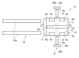
- FIG. 2 is a schematic top view showing a manufacturing device for a rolled body and a first conveyance device according to the first embodiment.
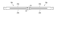
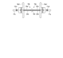
- FIG. 3 is a schematic view of a pair of winding shafts with their free ends separated from each other in the manufacturing device shown by solid lines in FIG. 2 and a flange that holds the pair of winding shafts.
- FIG. 3B is a schematic diagram showing a pair of winding shafts and flanges of the manufacturing device as seen from the direction indicated by reference numeral 3B in FIG. 3A.
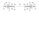
- FIG. 4 is a schematic diagram showing a state in which the free ends and flanges of a pair of winding shafts of the manufacturing apparatus shown in FIG. 3A are brought close to each other.
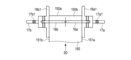
- FIG. 3C is a schematic diagram showing a pair of winding shafts and flanges of the manufacturing device as seen from the direction indicated by reference numeral 3D in FIG. 3C.
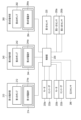
- FIG. 1 is a schematic block diagram of a manufacturing apparatus for a rolled body according to a first embodiment. Schematic diagrams showing the manufacturing process of the wound body according to the first embodiment.
- FIG. 1 is a schematic block diagram of a manufacturing apparatus for a rolled body according to a first embodiment. Schematic diagrams showing the manufacturing process of the wound body according to the first embodiment.
- FIG. 1 is a schematic block diagram of a manufacturing apparatus for
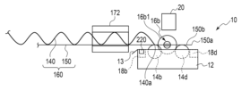
- FIG. 6 is a schematic diagram showing the manufacturing process of the wound body following FIG. 5 .
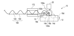
- FIG. 7 is a schematic diagram showing the manufacturing process of the wound body following FIG. 6 .
- FIG. 8 is a schematic diagram showing the manufacturing process of the wound body following FIG. 7 .
- FIG. 9 is a schematic diagram showing the manufacturing process of the wound body following FIG. 8 .
- 1 is a schematic flowchart showing a manufacturing process of a wound body according to a first embodiment.
- FIG. 7 is a schematic diagram of a moving mechanism of a winding device according to a modification.
- FIG. 12B is a schematic diagram of the moving mechanism seen from the direction indicated by arrow 12B in FIG. 12A.
- FIG. 7 is a schematic diagram showing a state in which the free ends of a core metal (a pair of winding shafts) are brought close to each other in an apparatus for manufacturing an exhaust gas purifying catalytic converter according to a second embodiment.
- FIG. 3 is a schematic view of a pair of winding shafts with their free ends separated from each other in the manufacturing device shown by solid lines in FIG. 2 and a flange that holds the pair of winding shafts.
- 13B is a schematic diagram showing a pair of winding shafts and flanges of the manufacturing device as seen from the direction indicated by reference numeral 13B in FIG. 13A.
- FIG. 13A is a schematic diagram showing a state in which the free ends of a pair of winding shafts and flanges of the manufacturing apparatus shown in FIG. 13A are brought close to each other.
- 13C is a schematic diagram showing a pair of winding shafts and flanges of the manufacturing device as seen from the direction indicated by reference numeral 13D in FIG. 13C.
- FIG. FIG. 7 is a schematic diagram showing a state in which a flat plate having a through hole is sandwiched between a slit of a core metal of an apparatus for manufacturing an exhaust gas purifying catalytic converter according to a second embodiment.
- the band-shaped flat plate 150 and the corrugated plate 140 arranged overlapping the flat plate 150 are rolled around an axis (core metal 16) orthogonal to the conveying direction of the flat plate 150 and the corrugated plate 140.
- An apparatus 10 for manufacturing a wound body (metal base material) 120 to be wound will be explained using FIGS. 1 to 11.
- a wound body 120 according to the present embodiment shown in FIG. 1 is used as a component housed in a cylindrical outer cylinder 110 of a catalytic converter 100 for purifying exhaust gas.
- FIG. 1 shows an outline of the manufacturing process of an exhaust gas purifying catalytic converter 100.
- a flat plate 130 for forming the corrugated plate 140 is prepared.
- the flat plate 130 for forming the corrugated plate 140 is preferably formed into a metal foil shape by rolling.
- a metal band-shaped flat plate 130 is sent between the pair of rollers 131 and 132, and the unevenness formed on the outer periphery of the pair of rollers 131 and 132 is transferred to form a metal band-shaped corrugated plate 140. That is, corrugation is performed to form a band-shaped metal flat plate 130 into a corrugated shape, thereby forming a band-shaped corrugated metal plate 140.
- the corrugated plate 140 is corrugated along the conveyance direction.
- a band-shaped flat plate 150 made of metal is stacked on the lower side of the corrugated sheet 140 to form an assembly 160. That is, the corrugated plate 140 is provided on the flat plate 150.
- the flat plate 150 is preferably formed into a metal foil shape by rolling.
- the control unit 200 of the manufacturing device 10 controls the first transport device 170 to transport the assembly body 160 toward the manufacturing device 10 of the rolled body 120.
- the feed chucks 171 and 172 (see FIGS. 1 and 5 to 7), which move the assembly body 160 along, for example, the rail 170a (see FIG. 2) of the first conveyance device 170 on the upstream side,
- the apparatus 10 for manufacturing the rolled body 120 forms the rolled body 120 by winding the flat plate 150 of the assembly body 160 and the metal corrugated plate 140 together in an overlapping state.
- the flat plate 150 is placed on the outside and the corrugated plate 140 is placed on the inside.
- a cylindrical outer tube 110 is arranged around the outer periphery of the wound body 120, and the shape of the wound body 120 is maintained by the outer tube 110.
- the wound body 120 is formed, for example, as a honeycomb body having a large number of through holes through which exhaust gas passes in the axial direction.
- a catalytic metal for purifying exhaust gas is supported on the surface of the honeycomb body that is in contact with a large number of through holes.
- the exhaust gas purifying catalytic converter 100 is disposed in front of or within the muffler in order to decompose, purify, and discharge harmful substances contained in the gas exhausted from the engine.
- Both the flat plate 150 and the corrugated plate 140 of the assembly body 160 are formed of, for example, a magnetic metal material.
- the flat plate 150 and the corrugated plate 140 may be formed as a ferromagnetic metal material, an example in which they are formed as a soft magnetic metal material will be described here.
- the flat plate 150 and the corrugated plate 140 are made of a material that has a low heat capacity and is excellent in heat resistance, pressure resistance, and the like.
- the flat plate 150 and the corrugated plate 140 are preferably made of stainless steel or heat-resistant steel, for example.
- martensitic stainless steel which is a soft magnetic material
- ferritic stainless steel which is a soft magnetic material
- austenitic stainless steel may be used as a soft magnetic material for the flat plate 150 and the corrugated plate 140 depending on the processing state.
- the corrugated plate 140 and the flat plate 150 of the assembly 160 have the same or substantially the same width.
- the width of the corrugated plate 140 and the flat plate 150 is, for example, about 60 mm.
- the thickness of the corrugated plate 140 and the flat plate 150 is, for example, about 50 ⁇ m.
- the tip 150a of the flat plate 150 of the assembly body 160 protrudes in the conveying direction with respect to the tip 140a of the corrugated plate 140.
- the amount of protrusion of the tip 150a of the flat plate 150 with respect to the tip 140a of the corrugated plate 140 of the assembly body 160 varies depending on the outer diameter (size) of the wound body 120 to be formed, and can be set as appropriate.
- the amount of protrusion of the tip 150a of the flat plate 150 with respect to the tip 140a of the corrugated plate 140 of the assembly body 160 is larger than the distance between the winding shafts 16a, 16b and the second magnets 18c, 18d.
- the region of the flat plate 150 between the tip 140a of the corrugated plate 140 of the assembly body 160 and the tip 150a of the flat plate 150 is referred to as a tip portion 150b.
- the amount of protrusion of the tip 150a of the flat plate 150 with respect to the tip 140a of the corrugated plate 140 of the assembly body 160 is preferably about 5 cm or more, for example.
- the base end (not shown) of the corrugated plate 140 of the assembly body 160 may be located at a position on the downstream side of the base end (not shown) of the flat plate 150 along the conveyance direction, or may be located at a position on the upstream side. It's okay.
- the base end of the corrugated plate 140 and the base end of the flat plate 150 of the assembly body 160 are located close to each other in the circumferential direction of the wound body 120.
- one end of the corrugated plate 140 in the width direction is designated by a reference numeral 141a, and the other end is designated by a reference numeral 141b.
- one end of the flat plate 150 in the width direction is designated by a reference numeral 151a, and the other end is designated by a reference numeral 151b.
- through holes 150c may be formed in the flat plate 150 at appropriate intervals. That is, as long as the flat plate 150 is transported to the manufacturing apparatus 10 as a flat plate, the degree of solidity, that is, the density may be different at appropriate positions. Furthermore, through holes may be formed in the corrugated plate 140 at appropriate intervals. When a through hole is formed in the corrugated sheet 140, it is preferable that the through hole is formed at the time of the flat plate 130 for the corrugated sheet 140, and then formed as the corrugated sheet 140. The sizes of the through holes in the flat plate 150 and the corrugated plate 140 may be the same or different.
- the presence of the through holes in the flat plate 150 and the corrugated plate 140 allows the exhaust gas to flow through the exhaust gas purification catalytic converter 100 and come into contact with the catalyst metal more, promoting purification of the exhaust gas. can do.
- the first conveyance device 170 conveys the assembly body 160 along a predetermined conveyance direction while holding the side surfaces of the assembly body 160 with the above-mentioned feed chucks 171 and 172. It is preferable that the conveyance path of the first conveyance device 170 is straight.
- FIG. 2 shows a schematic top view of the manufacturing device 10 of the rolled body 120 and the first conveyance device 170.
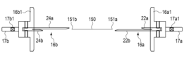
- FIG. 3 is a schematic diagram showing the free ends of the core bar 16 (take-up shafts 16a, 16b), which will be described later, facing each other and close to each other.
- FIG. 3A shows a schematic diagram of the winding shafts 16a, 16b with their free ends separated from each other of the manufacturing apparatus 10 shown by solid lines in FIG. 2, and the flanges 16a1, 16b1 that hold the winding shafts 16a, 16b.
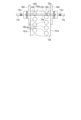
- FIG. 3B is a schematic diagram showing the winding shafts 16a, 16b and flanges 16a1, 16b1 of the manufacturing apparatus 10 as seen from the direction indicated by the reference numeral 3B in FIG. 3A.
- FIG. 3C the free ends of the manufacturing apparatus 10 shown by broken lines in FIG.
- FIG. 3D shows a schematic diagram of the winding shafts 16a, 16b and flanges 16a1, 16b1 of the manufacturing apparatus 10 as seen from the direction indicated by the symbol 3D in FIG. 3
- FIG. 4 shows a schematic block diagram of the manufacturing device 10 for the rolled body 120, the first conveyance device 170, and the second conveyance device 180.
- FIGS. 5 to 10 a series of manufacturing steps of the wound body 120 using the manufacturing apparatus 10 will be described. Note that FIGS. 5 to 10 are shown as views seen in the direction along the ⁇ - ⁇ line in FIG. 2.
- FIG. 11 is a flowchart illustrating a series of manufacturing steps for the rolled body 120 using the manufacturing apparatus 10.
- the manufacturing device 10 for the rolled body 120 according to the present embodiment is used together with the above-described first conveying device 170 (see FIG. 2) that conveys the assembly 160 toward the manufacturing device 10 for the rolled body 120. Moreover, the manufacturing device 10 for the wound body 120 according to the present embodiment is used together with a downstream second conveying device 180 (see FIGS. 9 and 10), which will be described later, and conveys the created wound body 120 in a predetermined direction. used.
- the manufacturing apparatus 10 of the wound body 120 includes a base 12, a support body 14 (rollers 14a to 14d) supported by the base 12, and a core metal 16 that grips a flat plate 150 of an assembly body 160 and rotates around its axis. (take-up shafts (straight shafts) 16a, 16b), and tension members 18 (magnets 18a- 18d) and an adjusting member 20 that adjusts the outer diameter of the wound body 120.
- the base 12 is formed into a block shape, for example.
- the base 12 is formed into a substantially rectangular parallelepiped shape.
- the base 12 is formed to be movable up and down by controlling an air cylinder 214 by a first operating section 210 shown in FIG.
- the first actuator 210 includes a first pump (compressed air supply source) 212 and a first solenoid valve 214a of the air cylinder 214.
- the first pump 212 supplies compressed air to an air cylinder 214 provided on the base 12.
- the first solenoid valve 214a switches the operating direction of the rod of the air cylinder 214 under the control of the control unit 200.
- the control section 200 controls the first electromagnetic valve 214a, so that the position of the rod of the air cylinder 214 provided on the base 12 is adjusted, and the height of the base 12 is adjusted.
- the base 12 has a guide portion 13 for the assembly body 160 at the upstream end.
- the guide portion 13 guides the assembly body 160 toward the upper surface of the base 12 so that the assembly body 160 is placed on first rollers 14a and 14b (support bodies) described later.
- the base 12 detects that the tip end 150b of the flat plate 150 of the assembly body 160 is placed on the base 12, and also detects that the rear end of the assembly body 160 (the base end of the flat plate 150 or the base of the corrugated plate 140) is placed on the base 12.
- a first sensor 220 is provided that detects the upstream end along the conveyance direction among the ends.
- the first sensor 220 is provided, for example, on the first transport device 170 side of the base 12.
- a photointerrupter light-shielding sensor
- a photoreflector that detects reflection of LED light or laser light may be used.
- the first sensor 220 is a photointerrupter, for example, a light source that emits an LED light or a laser beam is placed above the base 12, and the first sensor 220 has light blocked by at least one of the flat plate 150 and the corrugated plate 140. It is possible to output whether or not the When the first sensor 220 is a photoreflector, the first sensor 220 determines whether the light emitted from the LED light source or the laser light source is reflected by at least one of the flat plate 150 and the corrugated plate 140 and is received by the light receiving element. It is possible to output.
- a photointerrupter for example, a light source that emits an LED light or a laser beam is placed above the base 12, and the first sensor 220 has light blocked by at least one of the flat plate 150 and the corrugated plate 140. It is possible to output whether or not the When the first sensor 220 is a photoreflector, the first sensor 220 determines whether the light emitted from the LED light source or the laser light source is reflected by at least one
- a support body 14 is supported on the base 12.
- the support body 14 includes a pair of first rollers 14a, 14b on the upstream side and a pair of second rollers 14c, 14d on the downstream side, along the conveyance direction of the assembly body 160.
- the rotation axes of the pair of first rollers 14a, 14b and the pair of second rollers 14c, 14d are parallel to each other and perpendicular to the conveying direction of the first conveying device 170.
- a portion above the rotation axis protrudes with respect to the upper surface of the base 12.
- the base 12 is formed with openings for protruding a pair of first rollers 14a, 14b and a pair of second rollers 14c, 14d. Parts of 14c and 14d respectively protrude upwardly from the upper surface of the base 12 through the openings.
- first rollers 14a and 14b are spaced apart in a direction that is preferably perpendicular to, or intersects with, the conveyance direction of the assembly body 160.
- the pair of second rollers 14c, 14d are preferably spaced apart in a direction that intersects, such as perpendicularly, to the transport direction of the assembly 160.
- the width between the pair of first rollers 14a and 14b and between the pair of second rollers 14c and 14d is smaller than the width of the flat plate 150 of the assembly body 160. Therefore, the assembly body 160 conveyed by the first conveyance device 170 is placed on the pair of first rollers 14a, 14b, and also placed on the pair of second rollers 14c, 14d.
- first rollers 14a, 14b and the second rollers 14c, 14d are used for positioning the tip 150b of the flat plate 150 in relation to the core metal 16.
- the support body 14, that is, the rollers 14a to 14d are supported by the base 12 in this embodiment, and therefore move up and down together with the base 12.
- first rollers 14a, 14b and the pair of second rollers 14c, 14d may be formed to be actively rotated by, for example, a motor (not shown), and the assembly 160 may be configured to rotate passively by contact with the flat plate 150.
- the core metal 16 has a pair of winding shafts 16a and 16b facing each other so that their axial directions match.
- the axial direction of the winding shafts 16a, 16b is parallel to the pair of first rollers 14a, 14b and the pair of second rollers 14c, 14d. That is, the rotation axes of the pair of take-up shafts 16a and 16b are perpendicular to the transport direction of the first transport device 170.
- the fixed end sides of the pair of winding shafts 16a and 16b are supported by flanges 16a1 and 16b1, respectively.
- the flange 16a1 is provided with a shaft 17a having a rotation axis coaxial with the rotation axis of the first winding shaft 16a.
- the flange 16b1 is provided with a shaft 17b having a rotation axis coaxial with the rotation axis of the second winding shaft 16b.
- the shaft 17a is supported by the casing of the manufacturing apparatus 10 via a bearing 17a1 provided on the shaft 17a, and similarly, the shaft 17b is supported by the casing of the manufacturing apparatus 10 via a bearing 17b1 provided on the shaft 17b. Ru.
- These shafts 17a, 17b are moved in the same direction by, for example, controlling motors (for example, servo motors) 230a, 230b shown in FIG. Adjusted to rotate at the same speed and the same rotation angle. Note that when the shaft 17a rotates, the flange 16a1 and the first winding shaft 16a rotate in the same direction, at the same speed, and at the same rotation angle as the shaft 17a. Further, when the shaft 17b rotates, the flange 16b1 and the second winding shaft 16b rotate in the same direction, at the same speed, and at the same rotation angle as the shaft 17b.
- controlling motors for example, servo motors
- the rotation angles of the rotation shafts of the motors 230a and 230b, or the positions (rotation angles), speeds, and rotational forces of the pair of take-up shafts 16a and 16b via gears are acquired by encoders 232a and 232b.
- stepping motors can also be used instead of servo motors. If stepping motors are used as the motors 230a, 230b, the encoders 232a, 232b may be unnecessary. Alternatively, one of the motors 230a, 230b may be used to rotate the two winding shafts 16a, 16b in the same direction, at the same speed, and at the same rotation angle via a gear.
- the motors 230a and 230b cooperate with the control unit 200 to rotate the first winding shaft 16a and the second winding shaft 16b with the rotation shaft of the first winding shaft 16a and the second winding shaft 16b arranged coaxially.
- a rotation mechanism (200, 230a, 230b) is configured to synchronize and rotate the winding shaft 16a and the second winding shaft 16b in the same direction.
- the free ends of the pair of take-up shafts 16a, 16b are retracted from above the base 12 and can be moved to separate positions, as shown by solid lines in FIG. 2 or as shown in FIGS. 3A and 3B. . Further, the free ends of the pair of winding shafts 16a and 16b are movable to adjacent positions above the base 12, as shown by broken lines in FIG. 2 or as shown in FIGS. 3C and 3D. . The free ends of the pair of winding shafts 16a and 16b may not only be close to each other above the base 12, but also may be in contact with each other.
- the pair of take-up shafts 16a, 16b are moved in the axial direction by, for example, controlling an air cylinder 244 or the like.
- the second actuator (moving mechanism) 240 includes a second pump (compressed air supply source) 242 and a second solenoid valve 244a of the air cylinder 244.
- the second pump 242 supplies compressed air to air cylinders 244 provided on the pair of winding shafts 16a and 16b, respectively.
- the second electromagnetic valve 244a switches the operating direction of the rod of the air cylinder 244 under the control of the control unit 200.
- the air cylinder 244 having the second pump 242 and the second solenoid valve 244a cooperates with the control unit 200 to control the rotation axis of the first winding shaft 16a and the second winding shaft 16b.
- a moving mechanism is configured to move the free end of the first winding shaft 16a and the free end of the second winding shaft 16b in directions toward and away from each other while coaxially disposing the rotating shafts of the winding shaft 16a and the second winding shaft 16b.
- the air cylinder 244 By controlling the second pump (compressed air supply source) 242 of the second operating unit 240 that operates the pair of winding shafts 16a, 16b shown in FIG. 4 and the second solenoid valve 244a of the air cylinder 244, the air cylinder 244 are respectively driven, and the pair of winding shafts 16a, 16b are preferably moved in the axial direction in conjunction with each other. Note that the pair of winding shafts 16a and 16b are movable between the solid line position in FIG. 2 (see FIGS. 3A and 3B) and the broken line position (see FIGS. 3C and 3D). A disk-shaped flange 16a1 is provided on the winding shaft 16a. A disk-shaped flange 16b1 is provided on the winding shaft 16b.
- the maximum proximity position of the winding shafts 16a, 16b is defined by the flanges 16a1, 16b1 coming close to the side surface of the base 12 at a predetermined distance or coming into contact with the side surface of the base 12.
- the distance between the flanges 16a1 and 16b1 is formed to substantially match the width of the flat plate 150, or to be slightly larger than the width of the flat plate 150, so that meandering of the flat plate 150 is suppressed.
- the outer diameters of the flanges 16a1 and 16b1 are smaller than the outer diameter of the wound body 120 of the exhaust gas purifying catalytic converter 100 to be manufactured.
- the outer peripheral surfaces of the flanges 16a1 and 16b1 are prevented from interfering with, for example, the adjustment member 20. Note that, since the flanges 16a1 and 16b1 rotate together with the pair of winding shafts 16a and 16b, it is preferable that they do not actually come into contact with the side surfaces of the base 12.
- the pair of winding shafts 16a and 16b are preferably formed to have the same length and the same shape.
- the pair of winding shafts 16a and 16b are preferably formed as metal rods having a diameter of, for example, about 5 mm by processing a steel material having high rigidity and high toughness such as SUS440C or SKD11.
- the pair of winding shafts 16a, 16b are formed to have a first pair of opposing pieces 22a, 22b and a second pair of opposing pieces 24a, 24b as described below, and then are hardened, for example. It is preferable to use it after processing.
- One of the pair of winding shafts 16a, 16b (hereinafter referred to as the first winding shaft 16a) is supported by a flange 16a1 in a cantilever manner, and has first winding shafts facing each other defining a first slit 22 on the free end side. It has a pair of opposing pieces 22a and 22b. Among the first pair of opposing pieces 22a and 22b, one is designated as the 1-1 piece 22a, and the other is designated as the 1-2 piece 22b.
- the first winding shaft 16a has a free end divided into two parts, a 1-1 piece 22a and a 1-2 piece 22b.
- the 1-1 piece 22a and the 1-2 piece 22b be formed symmetrically with respect to the rotation axis of the first winding shaft 16a.
- the 1-1 piece 22a and the 1-2 piece 22b are spaced apart from each other by at least the thickness of the flat plate 150, and the position including the free end of the first winding shaft 16a is in the 1-1 piece.
- the first slit 22 is formed to penetrate in a direction intersecting (orthogonal to) the direction of separation between the first and second pieces 22a and 22b.
- At least the flat plate 150 is arranged in the first slit 22 defined between the 1-1 piece 22a and the 1-2 piece 22b.
- the axial length of the first slit 22 along the first winding shaft 16a is equal to or slightly larger than half the width of the flat plate 150. That is, the distance between the branching part of the 1-1 piece 22a and the 1-2 piece 22b and the free end of the 1-1 piece 22a and the 1-2 piece 22b is determined by the distance of the flat plate 150. It is formed to be equal to or slightly larger than half the width. Therefore, it is preferable that the length of the first slit 22 along the axial direction of the first winding shaft 16a is, for example, approximately half the width of the flat plate 150.
- the distance between the 1-1 piece 22a and the 1-2 piece 22b, that is, the size of the first slit 22, be the same from the branch part to the vicinity of the free end. be.
- the size of the first slit 22 is preferably increased toward the free end in order to guide the flat plate 150 to be received in the first slit 22 near the free end.
- the other of the pair of winding shafts 16a and 16b (hereinafter referred to as the second winding shaft 16b) is cantilevered by the flange 16b1, and faces each other to define a second slit 24 on the free end side. It has a second pair of opposing pieces 24a and 24b. Of the second pair of opposing pieces 24a, 24b, one is designated as the 2-1 piece 24a, and the other is designated as the 2-2 piece 24b.
- the second winding shaft 16b has a free end divided into two parts, a 2-1 piece 24a and a 2-2 piece 24b.
- the 2-1 piece 24a and the 2-2 piece 24b be formed symmetrically with respect to the rotation axis of the second winding shaft 16b.
- the 2-1 piece 24a and the 2-2 piece 24b are spaced apart from each other by at least the thickness of the flat plate 150, and the position including the free end of the second winding shaft 16b is in the 2-1 piece. It is formed as a second slit 24 that penetrates in a direction intersecting (orthogonal to) the direction of separation between the 24a and the 2-2 piece 24b. At least the flat plate 150 is arranged in the second slit 24 defined between the 2-1 piece 24a and the 2-2 piece 24b.
- the axial length of the second slit 24 along the second winding shaft 16b is formed to be equal to or slightly larger than half the width of the flat plate 150. That is, the distance between the branching part of the 2-1 piece 24a and the 2-2 piece 24b and the free end of the 2-1 piece 24a and the 2-2 piece 24b is determined by the distance of the flat plate 150. It is formed to be equal to or slightly larger than half the width. Therefore, it is preferable that the length of the second slit 24 along the axial direction of the second winding shaft 16b be approximately half the width of the flat plate 150, for example.
- the distance between the 2-1 piece 24a and the 2-2 piece 24b, that is, the size of the second slit 24, be the same from the branch part to the vicinity of the free end. be.
- the size of the second slit 24 is preferably larger toward the free end in order to guide the flat plate 150 to be received in the second slit 24 near the free end.
- the pair of winding shafts 16a and 16b have free ends of the 1-1 piece 22a and the 2-1 piece 24a facing each other in the horizontal direction, and the 1-1 piece 22a and the 2-1 piece 24a.
- the extension direction of the 2-1 piece 24a is adjusted so that it remains coaxially arranged.
- the pair of winding shafts 16a, 16b have free ends of the first-second piece 22b and the second-second piece 24b facing each other in the horizontal direction, and the first-second piece 22b and the second-second piece 24b.
- the extension direction of the 2-2 piece 24b is adjusted so that it remains coaxially arranged.
- the orientation of the first slit 22 and the orientation of the second slit 24 are aligned regardless of the rotational positions of the pair of winding shafts 16a, 16b. Therefore, the tip 150b of the flat plate 150 is inserted through the first slit 22 between the first pair of opposing pieces 22a, 22b and the second slit 24 between the second pair of opposing pieces 24a, 24b. .
- the pair of winding shafts 16a and 16b are moved from the position shown in FIG. 3B to a position where they grip the flat plate 150, and as shown in FIG. 3D, the 1-1st piece 22a and the 2-1st piece 24a are moved. is arranged on the upper side, and the 1-2nd piece 22b and the 2-2nd piece 24b are arranged on the lower side. At this time, the first slit 22 and the second slit 24 are connected to the upper 1-1 piece 22a and the 2-1 piece 24a, and the lower 1-2 piece 22b and the 2-2 piece. It is located horizontally between the piece 24b.
- the manufacturing apparatus 10 does not know whether the first slit 22 and the second slit 24 are located horizontally, and whether the tip 150b of the flat plate 150 is inserted into the first slit 22 and the second slit 24. It is preferable to have sensors 250a and 250b for detecting whether or not the user has performed the operation.
- the sensor 250a is provided, for example, on the flange 16a1
- the sensor 250b is provided, for example, on the flange 16b1.
- an optical sensor, an image sensor, or the like is used. If the sensors 250a, 250b are optical sensors, one is a laser oscillator and the other is a photodetector. If the sensors 250a and 250b are image sensors, the control unit 200 processes the images acquired by the image sensors and outputs whether the flat plate 150 is inserted into the first slit 22 and the second slit 24. It is possible.
- the core metal 16 that is, the pair of winding shafts 16a, 16b, the flanges 16a1, 16b1, the shafts 17a, 17b, and the bearings 17a1, 17b1 are separated from the base 12 and the support body 14, and the adjustment member 20, and preferably does not move up and down.
- the base 12 is provided with tension members 18 that pull the assembly 160 toward the support 14 on the upstream and downstream sides of the pair of take-up shafts 16a and 16b along the conveyance direction.
- the tension member 18 uses permanent magnets 18a, 18b, 18c, and 18d such as neodymium magnets.
- a pair of first magnets 18a, 18b are provided in the base 12 on the upstream side of the pair of winding shafts 16a, 16b.
- a pair of second magnets 18c and 18d are provided in the base 12 on the downstream side of the pair of winding shafts 16a and 16b.
- the pair of first magnets 18a, 18b are provided adjacent to the upstream side of the pair of first rollers 14a, 14b.
- the tensioning position of the flat plate 150 or the assembly body 160 in the tensioning member 18 is further upstream of the upstream support 14 (first rollers 14a, 14b) among the supports 14. Further, the pair of second magnets 18c and 18d are provided downstream and adjacent to the pair of second rollers 14c and 14d. Therefore, the tensioning position of the flat plate 150 in the tensioning member 18 is further downstream of the downstream support 14 (second rollers 14c, 14d) among the supports 14.
- a pair of first magnets 18a, 18b are provided as the tension member 18 at a corner of the base 12 on the upstream side with respect to the pair of winding shafts 16a, 16b. It is also suitable that one first magnet is provided at the center of the width direction of the first conveyance device 170 along the horizontal direction orthogonal to the conveyance direction. It is also preferable that three or more magnets be provided in the base 12 on the upstream side with respect to the pair of winding shafts 16a and 16b.
- a pair of second magnets 18c and 18d are provided as the tension member 18 at the corners of the base 12 on the downstream side with respect to the pair of winding shafts 16a and 16b.
- one second magnet is provided at the center in the width direction.
- three or more magnets be provided in the base 12 on the downstream side with respect to the pair of winding shafts 16a and 16b.
- An adjustment member 20 for adjusting the outer diameter of the wound body 120 is provided above the base 12 so as to be movable up and down above the winding shafts 16a and 16b.
- the adjusting member 20 cooperates with the support body 14 provided on the base 12 to adjust the outer diameter of the wound body 120.
- the adjusting member 20 is adjusted to move at the same speed in a direction opposite to the base 12 with respect to the winding shafts 16a and 16b.
- the third operating section 260 includes a third pump (compressed air supply source) 262 and a third solenoid valve 264a of the air cylinder 264.
- the third electromagnetic valve 264a switches the operating direction of the rod of the air cylinder 264 provided in the adjustment member 20 under the control of the control unit 200.
- the adjustment member 20 is adjusted by driving the air cylinder 264 under the control of the third pump (compressed air supply source) 262 of the third operating unit 260 and the third solenoid valve 264a of the air cylinder 264 shown in FIG.
- the member 20 moves up and down.
- the third pump 262 and the third electromagnetic valve 264a By controlling the third pump 262 and the third electromagnetic valve 264a by the control unit 200, the position of the rod of the air cylinder 264 provided in the adjustment member 20 is adjusted, and the height of the adjustment member 20 is adjusted.
- the adjustment member 20 is provided with a pressure sensor 266.
- the pressure sensor 266 can detect the contact pressure with the wound body 120.
- the control unit 200 can adjust the height of the adjustment member 20, that is, the outer diameter of the wound body 120, based on the detection data of the pressure sensor 266.
- the second conveying device 180 on the downstream side is formed to sandwich and hold the wound body 120 from the upper side and the lower side, respectively, and convey it to the downstream side, for example.
- the control unit 200 includes a first operating unit 210, a first sensor 220, motors 230a, 230b, encoders 232a, 232b, a second operating unit 240, and a 2-1st sensor 250a.
- the 2-2nd sensor 250b, the third operating section 260, and the pressure sensor 266 are connected by wire or wirelessly, and are controlled by the control section 200.
- the control unit 200 is connected to the first transport device 170 and the second transport device 180 by wire or wirelessly, and the first transport device 170 and the second transport device 180 are controlled by the control unit 200.
- the control unit 200 is connected to the first transport device 170 and the second transport device 180 by wire or wirelessly, and the first transport device 170 and the second transport device 180 are controlled by the control unit 200.
- the control unit 200 is composed of, for example, a computer, and includes a processor (processing circuit) and a storage medium.
- the processor includes any one of a CPU (Central Processing Unit), an ASIC (Application Specific Integrated Circuit), a microcomputer, an FPGA (Field Programmable Gate Array), a DSP (Digital Signal Processor), and the like.
- main storage such as memory
- the storage medium may include non-temporary auxiliary storage. Storage media include HDD (Hard Disk Drive), SSD (Solid State Drive), magnetic disk, optical disk (CD-ROM, CD-R, DVD, etc.), magneto-optical disk (MO etc.), semiconductor memory, etc. Examples include non-volatile memory that can be written and read at any time.
- control unit 200 only one processor and storage medium may be provided, or a plurality of processors and a plurality of storage media may be provided.
- a processor performs processing by executing a program or the like stored in a storage medium or the like.
- the program executed by the processor of the control unit 200 may be stored in a computer (server) connected to the control unit 200 via a network such as the Internet, or a server in a cloud environment. In this case, the processor downloads the program via the network.
- the manufacturing apparatus 10 operates based on instructions from the control section 200.
- the manufacturing apparatus 10 for the wound body 120 including the above-mentioned air cylinders 214, 244, 264, various motors, etc., is controlled by the control unit 200.
- the pair of winding shafts 16a and 16b are retracted from the upper surface of the base 12 to the sides perpendicular to the conveying direction, as shown by solid lines in FIG. be.
- the free ends of the pair of winding shafts 16a and 16b are retracted to a position away from the upper surface of the base 12.
- the first slit 22 and the second slit 24 of the pair of winding shafts 16a and 16b are oriented in the horizontal direction.
- the vertical center position of the first slit 22 and the second slit 24 of the pair of winding shafts 16a, 16b and the height of the upper surface of the support body 14 (rollers 14a to 14d) substantially match. .
- the assembly body 160 is placed on the base 12 along a predetermined transport direction by transport by the first transport device 170 under the control of the control unit 200 (see FIGS. 5 and 6).
- the flat plate 150 and the corrugated plate 140 of the assembly body 160 are conveyed by the feed chucks 171 and 172 with a predetermined length protruding from the feed chucks 171 and 172.
- the feed chucks 171 and 172 stop at predetermined positions, and the first sensor 220 detects that the tip end 150b of the flat plate 150 is placed on the base 12 (step S1).
- the control unit 200 proceeds to the next step (S2). Note that if the first sensor 220 cannot detect that the tip end 150b of the flat plate 150 of the assembly body 160 is placed on the base 12 (S1-No), the control unit 200 moves the tip end 150b of the flat plate 150 to the The detection operation with the sensor 220 of No. 1 is repeated.
- the amount of protrusion of the tip 150a of the flat plate 150 with respect to the tip 140a of the corrugated plate 140 of the assembly body 160 is greater than the distance between the winding shafts 16a, 16b and the second magnets 18c, 18d. big.
- the tip 150a of the flat plate 150 exceeds the position of the first magnets 18a, 18b and is above the second magnets 18c, 18d, the tip 140a of the corrugated plate 140 is connected to the pair of winding shafts 16a, 16b. The position has not yet been reached.
- the edge of the tip 150b of the flat plate 150 faces the branch of the first slit 22 and the branch of the second slit 24 of the pair of winding shafts 16a, 16b, respectively.
- the assembly body 160 is separated upward from the base 12 by the support body 14 (rollers 14a to 14d). Furthermore, even if the tip 150a of the flat plate 150 of the assembly body 160 is bent upward, for example, the flat plate 150 of the assembly body 160 is attached to the support body 14 by the tension member 18 (magnets 18a to 18d). Being pulled. The flat plate 150 may or may not be in contact with the base 12 by the tension member 18 . At this time, the tip portion 150b of the flat plate 150 is stretched between the first rollers 14a, 14b on the upstream side and the first rollers 14a, 14b on the downstream side.
- Step S2 controls the second pump 242 and the second solenoid valve 244a of the second operating unit 240, and moves the pair of winding shafts 16a, 16b from the solid line position to the broken line position in FIG. (Step S2). That is, the free ends of the pair of winding shafts 16a, 16b are close to or in contact with each other.
- the first slit 22 and second slit 24 of the pair of winding shafts 16a, 16b are oriented in the horizontal direction. Therefore, the tip portion 150b of the flat plate 150 of the assembly body 160 is inserted into the first slit 22 and the second slit 24 of the pair of winding shafts 16a, 16b. Therefore, the movement of the tip end 150b of the flat plate 150 in the vertical direction from the end of the flat plate 150 in the width direction to the center (near the middle) in the width direction is restricted by the pair of winding shafts 16a and 16b.
- a sensor 250a disposed in the housing of the manufacturing apparatus 10 determines whether the tip end 150b of the flat plate 150 is inserted into the first slit 22 and second slit 24 of the pair of winding shafts 16a, 16b. , 250b (step S3).
- the control unit 200 determines that the tip end 150b of the flat plate 150 is not inserted into the first slit 22 and the second slit 24 based on the signals from the sensors 250a and 250b (S3-No)
- the control unit 200 performs control.
- the unit 200 controls the second pump (compressed air supply source) 242 and second electromagnetic valve 244a of the second operating unit 240, and moves the pair of winding shafts 16a, 16b from the broken line position to the solid line position in FIG.
- control unit 200 determines multiple times based on the signals from the sensors 250a and 250b that the tip end 150b of the flat plate 150 is not inserted into the first slit 22 and the second slit 24 (S3-No) , outputs an error, terminates processing, and returns to the initial position.
- control unit 200 determines that the tip end 150b of the flat plate 150 has been inserted into the first slit 22 and the second slit 24 of the pair of winding shafts 16a and 16b based on the signals from the sensors 250a and 250b. (S3-Yes), the control unit 200 controls the third pump 262 and the third solenoid valve 264a of the third operating unit 260, and The outer diameter adjustment member 20 of the body 120 is lowered to the vicinity of the pair of winding shafts 16a and 16b (step S4).
- control unit 200 controls the motors 230a and 230b to rotate the pair of winding shafts 16a and 16b simultaneously in the same direction and at the same speed via gears, for example, to rotate the tip portion 150b including the tip 150a of the flat plate 150. , and separate them against the magnetic force of the magnets 18c and 18d. Therefore, the two pairs of opposing pieces 22a, 22b, 24a, 24b of the pair of winding shafts 16a, 16b support the flat plate 150 placed on the support body 14 so as to sandwich it therebetween. Then, the tip 140a of the corrugated plate 140 is sandwiched between the tip 150b of the flat plate 150.
- the pair of winding shafts 16a and 16b are rotated from the position shown in FIG. 6 to the position shown in FIG. 7. Therefore, the direction of rotation of the pair of winding shafts 16a, 16b is the direction in which the tip 150a of the flat plate 150 is separated from the magnets 18c, 18d.
- the magnetic force of the upstream magnets 18a and 18b is acting on the flat plate 150 and the corrugated plate 140. Therefore, on the base 12 on the upstream side of the pair of winding shafts 16a, 16b, the assembly body 160 is pulled (pressed) against the first rollers 14a, 14b by the magnetic force of the upstream magnets 18a, 18b. Power is at work.
- the pair of winding shafts 16a and 16b are further rotated to wind the assembly body 160, thereby creating the wound body 120 (step S5).
- the assembly 160 is wound on the base 12 on the upstream side of the pair of winding shafts 16a, 16b, the assembly 160 continues to be pulled toward the base 12 by the magnetic force of the magnets 18a, 18b.
- the feed chuck 171, 172 may be moved in a predetermined conveyance direction, and the flat plate 150 and the corrugated plate 140 may be pushed onto the pair of winding shafts 16a and 16b. By doing so, it is possible to suppress the initial wrapping failure of the tip 140a of the corrugated plate 140 at the tip 150b of the flat plate 150.
- the magnetic force of the magnets 18a and 18b also acts on the corrugated plate 140 on the flat plate 150. Therefore, by drawing the corrugated sheet 140 with magnets 18a, 18b on the upstream side of the pair of winding shafts 16a, 16b, warping of the corrugated sheet 140 is suppressed.
- the flat plate 150 and corrugated plate 140 of the assembly body 160 are suppressed from swinging, for example, vertically in the vicinity of the rollers 14a, 14b. Therefore, the behavior of the assembly body 160 when the assembly body 160 is rolled up as the wound body 120 on the upstream side of the base 12 can be stabilized.
- the free ends of the pair of winding shafts 16a and 16b are close to or in contact with each other. Therefore, the tip portion 150b of the flat plate 150 is held over substantially the entire width direction.
- the pair of winding shafts 16a and 16b continuously hold the flat plate 150 from the pair of ends 151a and 151b in the width direction to near the middle. Therefore, when the flat plate 150 and the corrugated plate 140 placed on the flat plate 150 are wound, the flat plate 150 can be wound while suppressing twisting.
- a pair of winding shafts 16a and 16b of the same size one end and the other end of the winding body 120 can be more closely spaced than when winding the winding body 120 using one winding shaft. dimensional stability can be ensured.
- the inner diameter of the center of one end of the wound body 120 and the inner diameter of the center of the other end can be kept substantially constant. Further, the free ends of the pair of winding shafts 16a and 16b hold the tip portion 150b of the flat plate 150 up to the vicinity of the center in the width direction. Therefore, by using the pair of winding shafts 16a and 16b, in addition to the inner diameter of the center between one end and the other end of the wound body 120, the inner diameter of the center of the area between the one end and the other end can be increased. It can be kept approximately constant.
- the flat plate 150 is wound using two winding shafts 16a and 16b with their free ends close to each other. Therefore, the total length of each of the two winding shafts 16a and 16b can be made shorter than when using one winding shaft. Therefore, when using the two winding shafts 16a and 16b according to this embodiment, the amount of deflection of the free end can be reduced compared to when winding the flat plate 150 using one winding shaft. Therefore, when using the two winding shafts 16a, 16b according to this embodiment, the outer diameters of the two winding shafts 16a, 16b can be made smaller than when using one winding shaft.
- the inner diameter of the center of the wound body 120 can be made as small as possible compared to the case where one winding shaft is used. Therefore, the wound body 120 manufactured by the manufacturing apparatus 10 according to the present embodiment can have a large contact area between the metal catalyst supported on the wound body 120 and the exhaust gas, and can improve the exhaust gas purification performance. can.
- the control unit 200 controls the first pump 212 and the first electromagnetic valve 214a of the first operating unit 210, and the second operating unit. 240, the second pump 242 and the second solenoid valve 244a are controlled, and the base 12 and the adjustment member 20 are adjusted to the rotation angle of the pair of take-up shafts 16a, 16b. evacuate to a distance from At this time, the base 12 is retracted downward relative to the pair of winding shafts 16a, 16b, and the adjustment member 20 is retracted upward relative to the pair of winding shafts 16a, 16b. Therefore, the support body 14 (rollers 14a to 14d) and the adjusting member 20 that protrude above the base 12 adjust the outer diameter of the wound body 120.
- the opposing surfaces of the pair of flanges 16a1 and 16b1 are formed, for example, as flat surfaces, and are spaced apart from each other by a distance greater than the width of the wound body 120 when the wound body 120 is wound.
- the mutually opposing surfaces of the pair of flanges 16a1 and 16b1 are arranged in parallel so that the ends of the flat plate 150 and the ends of the corrugated sheet 140 can be aligned.
- the widthwise end 141a of the corrugated sheet 140 is along the side of the flange 16a1 that faces the flange 16b1, and the widthwise end 141b of the corrugated sheet 140 is along the side of the flange 16b1 that faces the flange 16b1. Among them, it is along the side facing the flange 16a1.
- the distance between the pair of flanges 16a1 and 16b1, which are spaced apart from each other by a distance greater than the width of the wound body 120 is set to a distance that is approximately the same as the width of the wound body 120. controlled.
- the distance between the width direction ends 151a, 141a and the opposing surface of the flange 16a1 is set to 0.5 mm
- the separation distance between the width direction ends 151b, 141b and the opposing surface of the flange 16b1 is set to 0.5 mm. It is set. Therefore, the rolled body 120 is formed while the overlapping position of the corrugated sheet 140 and the flat plate 150 is corrected when the corrugated sheet 140 and the flat plate 150 are wound up.
- One end surface of the wound body 120 is formed such that the end 151a of the flat plate 150 and the end 141a of the corrugated sheet 140 are aligned, and the other end surface of the wound body 120 is formed such that the end 151a of the flat plate 150 and the end 141a of the corrugated sheet 140 are aligned.
- the portion 151b and the end portion 141b of the corrugated plate 140 are formed in alignment. Note that the distance between the widthwise ends 151a, 141a and the opposing surface of the flange 16a1 and the distance between the widthwise ends 151b, 141b and the opposing surface of the flange 16b1 are determined by the distance between the holes formed in the corrugated plate 140.
- the thickness is adjusted to about 0 mm to 1.0 mm depending on the presence or absence of holes formed in the flat plate 150 or the thickness of the foil material.
- the thickness of the flat plate 150 or the corrugated plate 140 is 30 ⁇ m to 50 ⁇ m
- the flat plate 150 or the corrugated sheet 140 is conveyed onto the base 12
- the corner between the tip 150a and the end 151a or 151b of the flat plate 150 and the corner between the tip 140a and the end 141a or 141b of the corrugated plate 140 contact the flange 16a1 and the flange 16b1, and the flat plate 150 Problems such as not being able to be inserted into the first slit 22 and second slit 24 of the winding shafts 16a and 16b, and being unable to wind up the tip 140a of the corrugated sheet 140 with the tip 150b of the flat plate 150 may occur.
- the foil material is thin, until the pair of winding shafts 16a and 16b are rotated and the tip 140a of the corrugated sheet 140 is sandwiched between the tip 150b of the flat plate 150, the widthwise ends of the flat plate 150 and the corrugated sheet 140 are It is preferable that the facing surfaces of the portions 151a and 141a and the flange 16a1 and the facing surfaces of the width direction ends 151b and 141b of the flat plate 150 and the corrugated sheet 140 and the flange 16b1 are spaced apart from each other.
- the flat plate 150 and the corrugated sheet 140 are inserted.
- the foil flat plate 150 or the corrugated sheet 140
- the foil are formed so that the end portion 151a of the flat plate 150 and the end portion 141a of the corrugated sheet 140 are aligned, and the end portion 151b of the flat plate 150 and the end portion of the corrugated sheet 140 are aligned.
- 141b can be formed in a uniform state.
- the control unit 200 determines whether or not the winding body 120 has been wound (step S6). If the control unit 200 determines that the winding body 120 has not finished winding (S6-No), the control unit 200 continues winding the winding body 120.
- the control unit 200 determines that the winding of the wound body 120 has been completed.
- the control unit 200 controls the winding body 120 when, for example, the amount of rotation (rotation angle) of the motors 230a, 230b of the pair of winding shafts 16a, 16b obtained by the encoders 232a, 232b exceeds a predetermined amount. It is determined that the winding has been completed.
- the control unit 200 determines that the winding body 120 has finished winding (S6-Yes)
- the control unit 200 controls the motors 230a and 230b to stop the rotation of the pair of winding shafts 16a and 16b.
- the control section 200 controls the first operating section 210 to stop the base 12 from lowering, and controls the third operating section 260 to stop the adjusting member 20 from rising. Therefore, the shape of the wound body 120 is maintained at the top and bottom by the support body 14 (rollers 14a to 14d) and the adjustment member 20, and the outer diameter of the wound body 120 is adjusted against the elastic force of the wound body 120. maintained.
- the adjustment member 20 is The pressure sensor 266 detects a reaction force based on the elastic deformation of the wound body 120. If the value detected by the pressure sensor 266 is within a predetermined pressure range, the control unit 200 can ignore the influence of the load on the pair of take-up shafts 16a, 16b. If the value detected by the pressure sensor 266 is out of the predetermined pressure range, the control unit 200 operates the third actuating unit 260 to move the adjustment member 20 upward, for example, so that the value detected by the pressure sensor 266 is Adjust so that the detected value falls within a predetermined range. Therefore, unintentional loading of a predetermined load or more on the pair of winding shafts 16a, 16b is suppressed.
- control unit 200 controls the second conveyance device 180 disposed on the downstream side in the conveyance direction with respect to the manufacturing apparatus 10, and transfers the rolled body 120 to the gripping members 181, 182 of the second conveyance device 180. (step S7).
- a groove 12a is formed on the upper surface of the base 12 with an appropriate length from the base end toward the distal end. Therefore, as shown in FIG. 9, the gripping member 182 is prevented from interfering with the base 12.
- the control unit 200 controls the motors 230a, 230b to slightly return the rotation angle of the pair of take-up shafts 16a, 16b, so that the outer circumferential surface of the pair of take-up shafts 16a, 16b (the 1-1 piece 22a , the outer peripheral surfaces of the 1-2nd piece 22b, the 2-1st piece 24a, and the 2-2nd piece 24b).
- the wound body 120 is supported by the adjustment member 20 and held between the gripping members 181 and 182 of the second conveyance device 180, so that the outer diameter is maintained. Therefore, the amount of change in the surface area of the inner diameter at the center of the wound body 120 is negligible.
- control unit 200 controls the second operating unit 240 to retract the pair of take-up shafts 16a, 16b from the broken line position shown in FIG. 2 to the solid line position (step S8). Subsequently, the control unit 200 controls the third operating unit 260 to retract the adjustment member 20 upward (step S9). At this time, the control section 200 controls the first operating section 210 to retract the base 12 and the support body 14 downward as necessary.
- the operation of reversing the rotation of the pair of winding shafts 16a, 16b and relaxing the winding force of the winding body 120 on the pair of winding shafts 16a, 16b is, for example, reversing the rotation of the pair of winding shafts 16a, 16b. After that, the reverse rotation and the normal rotation may be repeated several times, such as by causing the rotation to occur again in the normal direction.
- control unit 200 transports the rolled body 120 held between the gripping members 181 and 182 of the second transport device 180 to the downstream side (step S10), and also transports the base 12 and the support body 14 as shown in FIG. 5, for example. Raise it so that it matches the position.
- the manufacturing apparatus 10 does not use one winding shaft, but uses two winding shafts 16a and 16b with their free ends facing each other while aligning their rotational axes.
- the manufacturing apparatus 10 according to the present embodiment has each of the winding shafts 16a and 16b shorter than the case where one winding shaft is used to exhibit appropriate rigidity, and compared to the case where one winding shaft is used. Therefore, the outer diameter of each winding shaft 16a, 16b can be reduced. Therefore, according to the present embodiment, it is possible to provide an apparatus 10 for manufacturing a metal base material for exhaust gas purification in which the inner diameter of the central portion of the wound body 120 can be made as small as possible. Therefore, when manufacturing the wound body 120, the manufacturing apparatus 10 is provided which can make the inner diameter of the central portion of the wound body 120 smaller, thereby improving the exhaust gas purification performance.
- the assembly body 160 when manufacturing the wound body 120 using the assembly body 160 using the manufacturing apparatus 10, the assembly body 160 can be placed in a predetermined position by the tension member 18, and the flat plate 150 of the assembly body 160 can be stably wound.
- the flat plate 150 when moving the pair of winding shafts 16a and 16b from the retracted position shown by the solid line in FIG. 2 to the gripping position shown by the broken line, the flat plate 150 can be placed in a stable position. Therefore, the flat plate 150 can be gripped more reliably by the pair of winding shafts 16a and 16b. Therefore, failure in manufacturing the wound body 120 due to a gripping error between the pair of winding shafts 16a and 16b can be suppressed.
- the first magnets 18a and 18b continue to pull the flat plate 150 and the corrugated plate 140 toward the upstream end of the base 12. .
- the vertical vibration of the assembly body 160 that is, the flat plate 150 and the corrugated plate 140, can be suppressed, and the wound body 120 can be wound stably.
- first magnets 18a and 18b of the tension member 18 are provided on the base 12 .
- the first magnets 18a and 18b may be placed upstream of the base 12.
- the tension member 18 has been described as a permanent magnet such as a neodymium magnet.
- An electromagnet controlled by the control unit 200 may be used instead of a permanent magnet.
- the tension member 18 may be a suction part that has a negative pressure inside, such as a suction pad connected to a vacuum suction device.
- the suction section can pull the flat plate 150 to the base 12, the first rollers 14a, 14b, and the second rollers 14c, 14d.
- the vacuum suction device at this time may be controlled by the control unit 200, and a solenoid valve (not shown) connected to the vacuum suction device may be controlled by the control unit 200.
- the suction force of the suction unit is applied to the flat plate 150, but normally does not apply to the corrugated plate 140.
- the flat plate 150 can be stably transported toward the manufacturing apparatus 10 for the rolled body 120, and therefore the corrugated sheet 140 on the flat plate 150 can be stably transported on the flat plate 150. It can be transported in a number of ways. Therefore, even when a suction part is used as the tension member 18, the wound body 120 can be stably manufactured.
- the flat plate 150 and the corrugated plate 140 of the assembly body 160 may be made of an appropriate material such as martensitic stainless steel, ferritic stainless steel, or austenitic stainless steel, regardless of whether it is a soft magnetic material or not. can be used. Further, as described above, the flat plate 150 has a through hole (opening) as appropriate. Therefore, depending on the location, suction force may act not only on the flat plate 150 but also on the corrugated plate 140.
- the magnets 18a and 18b are arranged upstream of the winding shafts 16a and 16b, and the suction part instead of the magnet is arranged upstream of the winding shafts 16a and 16b. Good too.
- rollers 14a to 14d are used as the support body 14 .
- a spherical body may be used instead of the rollers 14a to 14d.
- the base 12 is not necessarily necessary as long as the support body 14 and the tension member 18 can maintain the above-mentioned relative positions.
- an example has been described in which an assembly body 160 in which a metal flat plate 150 is stacked on the lower side of a corrugated metal corrugated plate 140 is conveyed toward the manufacturing apparatus 10 for the wound body 120.
- An assembly body 160 in which a metal flat plate 150 is stacked on top of a corrugated metal corrugated sheet 140 may be transported toward the manufacturing apparatus 10 for the rolled body 120 to form the rolled body 120.
- the rotation direction of the pair of winding shafts 16a and 16b is opposite to that of the assembly 160 in which the corrugated sheet 140 is stacked on the flat plate 150 described above.
- the force of the tension member 18 acts on the upper flat plate 150 in addition to the lower corrugated plate 140. Therefore, when manufacturing the wound body 120 by rotating the pair of winding shafts 16a and 16b using the assembly body 160 in which the corrugated plate 140 is arranged on the lower side and the flat plate 150 is arranged on the upper side, the first The magnets 18a and 18b continue to pull the lower corrugated plate 140 and the upper flat plate 150 toward the upstream end of the base 12. For this reason, the vertical vibration of the assembly body 160, that is, the flat plate 150 and the corrugated plate 140, can be suppressed, and the wound body 120 can be wound stably.
- the rolled body 120 is formed using the manufacturing apparatus 10 for the rolled body 120 according to the present embodiment.
- the adjustment member 20 is provided with a pressure sensor 266, and the third operating section 260 is operated based on the output value of the pressure sensor 266 to suppress the load on the pair of winding shafts 16a and 16b.
- a strain gauge is attached to the pair of take-up shafts 16a, 16b to measure the strain in real time, and based on the measured value, the third operating section 260 is operated to apply pressure to the pair of take-up shafts 16a, 16b.
- the load may be suppressed. That is, there may be various means for suppressing the load on the pair of winding shafts 16a, 16b during manufacturing of the wound body 120.
- the tip of the corrugated plate 140 may be inserted through the first slit 22 and the second slit 24.
- the tip of the corrugated plate 140 may be inserted through the first slit 22 and the second slit 24. That is, the tip of the corrugated plate 140 may protrude further in the conveyance direction than the tip 150a of the flat plate 150.
- At least the flat plate 150 and/or the corrugated plate 140 are arranged in the first slit 22 and the second slit 24 such that they can be inserted into the first slit 22 and the second slit 24 .
- the tip of the corrugated plate 140 may be formed as a flat surface like the tip 150b of the flat plate 150, or may be formed as a corrugated portion.
- the pair of winding shafts 16a and 16b are controlled by the control unit 200 controlling the second actuating unit (moving mechanism) 240 having the second pump 242 and the air cylinder 244 as the moving mechanism.
- the manufacturing apparatus 10 has a pair of racks 272a, 272b, a pinion gear 274 meshed between the pair of racks 272a, 272b, and a motor 276 as a moving mechanism. It's okay.
- These pair of racks 272a, 272b, pinion gear 274, and motor 276 are provided at positions where they do not interfere with, for example, the vertical movement of the base 12 and the vertical movement of the adjustment member 20.
- These pair of racks 272a, 272b, pinion gear 274, and motor 276 are preferably provided below the base 12.
- the motor 276 may have a structure in which the pinion gear 274 is rotated by a desired angle using a stepping motor or the like.
- the flange 16a1 is rotatably supported around the first winding shaft 16a by a support member 278a provided on one of the racks 272a of the pair of racks 272a and 272b.
- the flange 16b1 may be rotatably supported around the second winding shaft 16b by a support member 278b provided on the other rack 272b.
- the extending direction of the pair of racks 272a and 272b is parallel to the width direction of the flat plate 150 and the corrugated plate 140.
- the control unit 200 rotates the motor 276, the pair of racks 272a and 272b move in conjunction with the rotation of the pinion gear 274, and the support members 278a and 278b and the flanges 16a1 and 16b1 move closer to each other or farther apart. That is, the free ends of the winding shafts 16a and 16b are brought close to each other or separated from each other.
- the moving mechanism may be formed in this way.
- FIGS. 13 to 13D An apparatus 10 for manufacturing a wound body (metal base material) 120 according to a second embodiment will be described using FIGS. 13 to 13D.
- This embodiment is a modification of the first embodiment, and the same members or members having the same functions as those described in the first embodiment are denoted by the same reference numerals, and detailed description thereof will be omitted.
- FIG. 13 shows a schematic diagram in which the free ends of the core bar 16 (take-up shafts 16a, 16b) are brought close to each other.
- FIG. 13A shows a schematic diagram of the winding shafts 16a, 16b with their free ends separated from each other of the manufacturing apparatus 10 shown by solid lines in FIG. 2, and the flanges 16a1, 16b1 that hold the winding shafts 16a, 16b.
- FIG. 13B is a schematic diagram showing the winding shafts 16a, 16b and flanges 16a1, 16b1 of the manufacturing apparatus 10 as seen from the direction indicated by the reference numeral 13B in FIG. 13A.
- FIG. 13C shows a schematic diagram of the manufacturing apparatus 10 shown in FIG.
- FIG. 13A shows a schematic diagram of the winding shafts 16a, 16b and flanges 16a1, 16b1 of the manufacturing apparatus 10 as seen from the direction indicated by the reference numeral 13D in FIG. 13C.
- the pair of winding shafts 16a, 16b are formed in the same shape.
- the pair of winding shafts 16a and 16b are preferably formed as metal rods having a diameter of about 4 mm, for example, by processing a steel material such as SUS440C or SKD11. Note that the pair of winding shafts 16a and 16b are preferably used after forming the first slit 22 and the second slit 24 and then, for example, being hardened.
- the 1-1 piece 22a and the 1-2 piece 22b of the first winding shaft 16a described in the first embodiment are formed asymmetrically.
- the 1-1 piece 22a will be referred to as the first short piece 22a
- the 1-2 piece 22b will be referred to as the first long piece 22b, which is longer than the first short piece 22a.
- the length from the branch part to the free end of the first short piece 22a is shorter than half the width of the flat plate 150, and the length from the branch part to the free end of the first long piece 22b is shorter than the width of the flat plate 150. Formed longer than half.
- the space between the first short piece 22a and the first long piece 22b is formed as a first slit 22 that is spaced apart by at least the thickness of the flat plate 150. Therefore, the axial length of the first slit 22 along the first winding shaft 16a is defined as the length from the branching part of the first short piece 22a to the free end. Further, the distance between the first short piece 22a and the first long piece 22b, that is, the size of the first slit 22, must be the same from the branch part to the vicinity of the free end of the first short piece 22a. is suitable.
- the size of the first slit 22 is preferably increased toward the free end in order to guide the flat plate 150 to be received in the first slit 22 near the free end of the first short piece 22a. It is.
- the free end of the first long piece 22b is closer to the free end of the first long piece 22b than the free end of the first short piece 22a, and guides the flat plate 150 to be received in the first slit 22. Therefore, it is preferable that the size increases toward the free end side of the first long piece 22b.
- At least the flat plate 150 is arranged in the first slit 22 defined between the first short piece 22a and the first long piece 22b.
- the 2-1 piece 24a and the 2-2 piece 24b of the second winding shaft 16b described in the first embodiment are formed asymmetrically.
- the 2-1 piece 24a will be referred to as the second long piece 24a
- the 2-2 piece 24b will be referred to as the second short piece 24b shorter than the second long piece 24a.
- the length from the branch to the free end of the second long piece 24a is longer than half the width of the flat plate 150, and the length from the branch to the free end of the second short piece 24b is longer than the width of the flat plate 150. Formed shorter than half.
- the second long piece 24a and the second short piece 24b are spaced apart from each other by at least the thickness of the flat plate 150, and are formed as a second slit 24. Therefore, the axial length of the second slit 24 along the second winding shaft 16b is defined as the length from the branching part of the second short piece 24b to the free end.
- the distance between the second long piece 24a and the second short piece 24b that is, the size of the second slit 24, must be the same from the branch part to the vicinity of the free end of the second short piece 24b. is suitable.
- the size of the second slit 24 is preferably increased toward the free end in order to guide the flat plate 150 to be received in the second slit 24 near the free end of the second short piece 24b. It is. Further, the free end of the second long piece 24a is closer to the free end of the second long piece 24a than the free end of the second short piece 24b, and guides the flat plate 150 to be received in the second slit 24. Therefore, it is preferable that the size increases toward the free end side of the second long piece 24a.
- At least the flat plate 150 is arranged in the second slit 24 defined between the second long piece 24a and the second short piece 24b.
- the pair of winding shafts 16a and 16b have free ends of the first short piece 22a and the second long piece 24a facing each other in the horizontal direction, and the first short piece 22a and the second long piece 24a facing each other in the horizontal direction. Adjustments are made so that the extending direction of the cylindrical member 24a is maintained coaxially. Further, in the pair of winding shafts 16a, 16b, the free ends of the first long piece 22b and the second short piece 24b are horizontally opposed to each other, and the first long piece 22b and the second short piece 24b are opposite to each other in the horizontal direction. Adjustments are made so that the extending direction of 24b remains coaxially arranged. Therefore, the orientation of the first slit 22 and the orientation of the second slit 24 are aligned. Therefore, the flat plate 150 is inserted through the first slit 22 between the first pair of opposing pieces 22a, 22b and the second slit 24 between the second pair of opposing pieces 24a, 24b.
- the first short piece 22a and the second long piece 24a are on the upper side
- the first long piece 22b and the second short piece 24b are on the lower side.
- the length from the branch to the free end of the first short piece 22a of the first winding shaft 16a is relatively short, less than half the width of the flat plate 150, so the rigidity is relatively high. Therefore, even if the outer diameter of the first winding shaft 16a according to the present embodiment is thinner than the outer diameter of the first winding shaft 16a described in the first embodiment, the first short piece 22a can be freely moved. It is understood that the deflection at the end is smaller than the deflection at the free end of the first short piece 22a described in the first embodiment. Further, the first short piece 22a cooperates with the first long piece 22b facing the first short piece 22a to hold one end 151a side of the flat plate 150 along the width direction.
- the length of the second short piece 24b of the second winding shaft 16b from the branch to the free end is relatively short, less than half the width of the flat plate 150, and therefore has relatively high rigidity. Therefore, even if the outer diameter of the second winding shaft 16b according to the present embodiment is thinner than the outer diameter of the second winding shaft 16b explained in the first embodiment, the second short piece 24b can be freely moved. It is understood that the deflection at the end is smaller than the deflection at the free end of the second short piece 24b described in the first embodiment. Further, the second short piece 24b cooperates with the second long piece 24a facing the second short piece 24b to hold the other end 151b side of the flat plate 150 along the width direction.
- the ends 151a and 151b in the width direction of the flat plate 150 are connected to the first long piece 22b and the second winding shaft of the first winding shaft 16a, respectively, which are longer than half the width of the flat plate 150. It is held by the second long piece 24a of the shaft 16b.
- the free end of the first winding shaft 16a and the free end of the second winding shaft 16b are brought close to each other or in contact with each other, the free end of the first short piece 22a and the free end of the second long piece 24a are free.
- the end is shifted from the center of the flat plate 150 in the width direction toward the first width direction end portion 151a.
- the free end of the first long piece 22b and the free end of the second short piece 24b are located at a second width opposite to the first widthwise end 151a side from the widthwise center of the flat plate 150. It is shifted toward the direction end portion 151b.
- the protrusion length along the axial direction of the first winding shaft 16a of the first long piece 22b with respect to the first short piece 22a is the protrusion length of the second winding shaft 16b of the second long piece 24a with respect to the second short piece 24b. It is the same distance as the protrusion length along the axial direction.
- the tip end 150b of the flat plate 150 is held by the first winding shaft 16a and the second winding shaft 16b over almost the entire width direction.
- the pair of winding shafts 16a and 16b continuously hold the flat plate 150 from the pair of ends 151a and 151b in the width direction to near the middle. Therefore, when the manufacturing apparatus 10 rotates the pair of winding shafts 16a and 16b in the same direction at the same speed and winds the flat plate 150 and the corrugated sheet 140 placed on the flat plate 150, the flat plate 150 mm can be wound while suppressing twisting.
- one end and the other end of the winding body 120 can be more closely spaced than when winding the winding body 120 using one winding shaft.
- dimensional stability can be ensured. That is, by using a pair of winding shafts 16a and 16b of the same size, the inner diameter of the center of one end of the wound body 120 and the inner diameter of the center of the other end can be kept substantially constant. Further, the pair of winding shafts 16a and 16b hold the tip portion 150b of the flat plate 150 near the center in the width direction by the first long piece 22b and the second long piece 24a.
- the inner diameter of the center of the area between the one end and the other end can be increased. It can be kept approximately constant.
- the flat plate 150 is wound using two winding shafts 16a and 16b with their free ends horizontally close to each other. Therefore, the total length of each of the two winding shafts 16a and 16b can be made shorter than when using one winding shaft. Therefore, when using the two winding shafts 16a and 16b according to this embodiment, the amount of deflection of the free end can be reduced compared to when the flat plate 150 is wound using one winding shaft. Therefore, when using the two winding shafts 16a, 16b according to this embodiment, the outer diameters of the two winding shafts 16a, 16b can be made smaller than when using one winding shaft.
- the winding body 120 is manufactured using a single winding shaft.
- the inner diameter of the center portion of 120 can be made as small as possible. Therefore, the wound body 120 manufactured by the manufacturing apparatus 10 according to the present embodiment can have a large contact area between the metal catalyst supported on the wound body 120 and the exhaust gas, and can improve the exhaust gas purification performance. can.
- FIG. 14 is a schematic diagram showing a state in which a flat plate 150 having a through hole 150c is sandwiched between the slits 22 and 24 of the core bar 16 of the apparatus 10 for manufacturing an exhaust gas purifying catalytic converter according to the present embodiment. That is, through holes 150c of appropriate sizes are formed in the flat plate 150 at appropriate intervals. Although further through holes may be formed in the corrugated plate 140 similarly to the through holes 150c, illustration thereof is omitted.
- the through hole 150c of the flat plate 150 may be located directly above the opposing position. Even in this case, the tip portion 150b of the flat plate 150 is held by the first winding shaft 16a and the second winding shaft 16b over substantially the entire widthwise direction.
- the pair of winding shafts 16a and 16b continuously hold the flat plate 150 from the pair of ends 151a and 151b in the width direction to near the middle.
- the manufacturing apparatus 10 rotates the pair of winding shafts 16a and 16b in the same direction at the same speed and winds the flat plate 150 and the corrugated sheet 140 placed on the flat plate 150, the flat plate 150 mm can be wound while suppressing twisting.
- one end and the other end of the winding body 120 can be more closely spaced than when winding the winding body 120 using one winding shaft.
- dimensional stability can be ensured. That is, by using a pair of winding shafts 16a and 16b of the same size, the inner diameter of the center of one end of the wound body 120 and the inner diameter of the center of the other end can be kept substantially constant. Further, the pair of winding shafts 16a and 16b hold the tip portion 150b of the flat plate 150 near the center in the width direction by the first long piece 22b and the second long piece 24a.
- the inner diameter of the center of the wound body 120 can be increased. It can be kept approximately constant. Furthermore, as described above, when manufacturing the wound body 120 using the two winding shafts 16a and 16b according to this embodiment, compared to the case where the winding body 120 is manufactured using one winding shaft. Thus, the inner diameter of the center of the wound body 120 can be made as small as possible.
- the rolled body 120 manufactured by the manufacturing apparatus 10 according to the present embodiment has the through hole 150c in the flat plate 150, the amount of metal supported on the rolled body 120 is higher than in the case where the flat plate 150 does not have the through hole 150c.
- the contact area between the catalyst and exhaust gas can be increased, and the exhaust gas purification performance can be improved.
- the mating portion of the core metal 16 (the position where the first short piece 22a and the first piece 22b are close to each other or in contact with each other and face each other, And, the positions where the second long piece 24a and the second short piece 24b are close to each other or in contact with each other and face each other) are set at two positions shifted from the center in the width direction of the flat plate 150. Therefore, when the flat plate 150 is wound up by the core metal 16, the tensile force that may be exerted on the flat plate 150 from the mating portion of the core metal 16 can be dispersed and reduced, and the flat plate 150 can be prevented from twisting.
- the central part of the flat plate 150 Since there is no through hole 150c, the central part of the flat plate 150 has relatively higher strength than the area of the flat plate 150 where the through hole 150c is present, and the reaction force on the core bar 16 when the wound body 120 is wound is reduced. is assumed to be higher than the region where the through hole 150c is formed.
- the mating portion of the core metal 16 does not overlap the widthwise central portion of the flat plate 150 where the through hole 150c is not provided. That is, the position of the mating portion of the core metal 16 is shifted with respect to the center portion of the flat plate 150 where the core metal 16 is assumed to receive the largest load when the flat plate 150 is wound up. Therefore, when the flat plate 150 is wound up by the core metal 16, the amount of deformation of the core metal 16, especially the first long piece 22b and the second long piece 24a, is reduced, and the flat plate 150 is prevented from twisting. can do.
- the length of the first long piece 22b protruding from the first short piece 22a and the length of the second long piece 24a protruding from the second short piece 24b are set as appropriate.
- the length of the first long piece 22b that protrudes from the first short piece 22a and the length of the second long piece 24a that protrudes from the second short piece 24b may be the same. , may not be the same.
- Such a length may vary depending on, for example, the position of the through hole 150c provided in the flat plate 150.
- the present invention is not limited to the above-described embodiments, and can be variously modified at the implementation stage without departing from the gist thereof.
- each embodiment may be implemented in combination as appropriate, and in that case, the combined effect can be obtained.
- the embodiments described above include various inventions, and various inventions can be extracted by combinations selected from the plurality of constituent features disclosed. For example, if a problem can be solved and an effect can be obtained even if some constituent features are deleted from all the constituent features shown in the embodiment, the configuration from which these constituent features are deleted can be extracted as an invention.
Landscapes
- Engineering & Computer Science (AREA)
- Chemical & Material Sciences (AREA)
- Chemical Kinetics & Catalysis (AREA)
- Mechanical Engineering (AREA)
- Combustion & Propulsion (AREA)
- Organic Chemistry (AREA)
- Materials Engineering (AREA)
- Health & Medical Sciences (AREA)
- Biomedical Technology (AREA)
- Environmental & Geological Engineering (AREA)
- Analytical Chemistry (AREA)
- General Chemical & Material Sciences (AREA)
- Oil, Petroleum & Natural Gas (AREA)
- Catalysts (AREA)
- Controlling Rewinding, Feeding, Winding, Or Abnormalities Of Webs (AREA)
Abstract
Description
第1実施形態に係る、帯状の平板150と平板150に重ねて配置される波板140とを平板150及び波板140の搬送方向に直交する軸(芯金16)の軸回りにロール状に巻回する巻回体(メタル基材)120の製造装置10について、図1から図11を用いて説明する。
アセンブリ体160の平板150及び波板140は、ともに、例えば磁性体の金属材として形成される。平板150及び波板140は、強磁性体の金属材として形成されてもよいが、ここでは、軟磁性体の金属材として形成される例について説明する。平板150及び波板140は、熱容量が低く、耐熱性、耐圧性等に優れている素材が用いられる。平板150及び波板140は、一例としてステンレス鋼材、耐熱鋼が用いられることが好適である。本実施形態では、軟磁性体のマルテンサイト系ステンレス、軟磁性体のフェライト系ステンレスが用いられることが好適である。なお、オーステナイト系ステンレスであっても、加工状態により、軟磁性体として平板150及び波板140に用いることができ得る。
なお、アセンブリ体160の波板140の先端140aに対する平板150の先端150aの突出量は、一例として、5cm程度以上であることが好適である。アセンブリ体160の波板140の基端(図示せず)は、平板150の基端(図示せず)よりも搬送方向に沿って下流側の位置にあってもよく、上流側の位置にあってもよい。巻回体120として形成されたときに、アセンブリ体160の波板140の基端と平板150の基端とが巻回体120の周方向に近接した位置にあることが好適である。
なお、フランジ16a1,16b1は、一対の巻取軸16a,16bとともに回転するため、実際にはベース12の側面には当接しないことが好適である。
第3の作動部260は、第3のポンプ(圧縮空気供給源)262及びエアシリンダー264の第3の電磁弁264aを有する。第3の電磁弁264aは、制御部200の制御により、調整部材20に設けられるエアシリンダー264のロッドの動作方向が切り替えられる。調整部材20は、図4に示す第3の動作部260の第3のポンプ(圧縮空気供給源)262及びエアシリンダー264の第3の電磁弁264aの制御により、エアシリンダー264が駆動され、調整部材20が上下に移動する。制御部200が第3のポンプ262及び第3の電磁弁264aを制御することで、調整部材20に設けられるエアシリンダー264のロッドの位置が調整され、調整部材20の高さが調整される。
吸引部の吸引力は平板150に及ぶが、通常は波板140には及ばない。しかしながら、平板150に吸引力を安定的に及ぼすことにより、平板150を安定的に巻回体120の製造装置10に向けて搬送でき、したがって、平板150上の波板140を平板150上で安定的に搬送することができる。したがって、引張部材18として吸引部を用いる場合であっても、安定的に巻回体120を製造することができる。この場合、アセンブリ体160の平板150及び波板140には、軟磁性体であるか否かに無関係に、マルテンサイト系ステンレス、フェライト系ステンレスの他、オーステナイト系ステンレス等のステンレスなど、適宜の素材を用いることができる。
また、上述したように、平板150は、適宜に貫通孔(開口)を有する。このため、場所によっては、平板150だけでなく、波板140にも、吸引力が作用し得る。
このため、下側に波板140を配置し上側に平板150を配置したアセンブリ体160を用いて、一対の巻取軸16a,16bを回転させ、巻回体120を製造するとき、第1の磁石18a,18bで下側の波板140及び上側の平板150をベース12の上流側端部に向かって引っ張り続ける。このため、アセンブリ体160すなわち平板150及び波板140が、上下に振れる大きさを抑制でき、巻回体120の巻回を安定して行うことができる。
上述した第1実施形態では、移動機構として、第2のポンプ242及びエアシリンダー244を有する第2の作動部(移動機構)240を制御部200で制御することにより一対の巻取軸16a,16bを相対的に近接又は離隔させる例について説明した。図12A及び図12Bに示すように、製造装置10は、移動機構として、一対のラック272a,272bと、一対のラック272a,272b間に噛み合わせられるピニオンギヤ274と、モータ276とを有するものであってもよい。これら一対のラック272a,272b、ピニオンギヤ274、及び、モータ276は、例えばベース12の上下の移動、調整部材20の上下の移動に干渉しない位置に設けられる。これら一対のラック272a,272b、ピニオンギヤ274、及び、モータ276は、ベース12の下側に設けられることが好適である。モータ276は、ピニオンギヤ274をステッピングモータ等により所望の角度回転させる構造としてもよい。
移動機構は、このように形成されてもよい。
第2実施形態に係る巻回体(メタル基材)120の製造装置10について、図13から図13Dを用いて説明する。本実施形態は第1実施形態の変形例であって、第1実施形態で説明した部材と同一の部材又は同一の機能を有する部材には同一の符号を付し、詳しい説明を省略する。
Claims (3)
- 平板と、前記平板上に設けられる波板とが巻回されて形成される排ガス浄化用メタル基材の製造装置であって、
片持ち支持され、自由端側に第1のスリットを規定する互いに対向する第1の一対の対向片を有する第1の巻取軸と、
片持ち支持され、自由端側に第2のスリットを規定する互いに対向する第2の一対の対向片を有する第2の巻取軸と、
前記第1の巻取軸の回転軸と前記第2の巻取軸の回転軸を同軸上に配置し、当該第1の巻取軸の自由端と当該第2の巻取軸の自由端とを対向させ、少なくとも前記平板及び/又は前記波板を、前記第1のスリットと前記第2のスリットとに挿通可能に配置し、前記第1の巻取軸及び前記第2の巻取軸を同期させて同一方向に回転させる回転機構と、
前記第1の巻取軸の回転軸及び前記第2の巻取軸の回転軸を同軸上に配置しながら前記第1の巻取軸の前記自由端と前記第2の巻取軸の前記自由端とを近接又は離隔させる方向に移動させる移動機構と
を有する、排ガス浄化用メタル基材の製造装置。 - 前記第1の巻取軸の前記第1の一対の対向片は、前記第1の巻取軸の固定端側から前記第2の巻取軸の前記自由端に向かって延びる第1の短片と、前記第1の巻取軸の前記固定端側から前記第2の巻取軸の前記自由端に向かって延び、前記第1の短片よりも長い第1の長片とを有し、
前記第2の巻取軸の前記第2の一対の対向片は、前記第2の巻取軸の固定端側から前記第1の巻取軸の前記自由端に向かって延びる第2の長片と、前記第2の巻取軸の前記固定端側から前記第1の巻取軸の前記自由端側に向かって延び、前記第2の長片よりも短い第2の短片とを有し、
前記第1の短片と前記第2の長片とは前記第1の巻取軸の回転軸及び前記第2の巻取軸の回転軸に沿って対向し、
前記第1の長片と前記第2の短片とは前記第1の巻取軸の回転軸及び前記第2の巻取軸の回転軸に沿って対向して配置される、
請求項1に記載の製造装置。 - 前記第1の短片に対する前記第1の長片の前記第1の巻取軸の軸方向に沿う突出長は、前記第2の短片に対する前記第2の長片の前記第2の巻取軸の軸方向に沿う突出長と等距離である、請求項2に記載の製造装置。
Priority Applications (2)
| Application Number | Priority Date | Filing Date | Title |
|---|---|---|---|
| CN202380062171.4A CN119816368A (zh) | 2022-09-02 | 2023-08-22 | 废气净化用金属基材的制造装置 |
| JP2023574723A JP7439346B1 (ja) | 2022-09-02 | 2023-08-22 | 排ガス浄化用メタル基材の製造装置 |
Applications Claiming Priority (2)
| Application Number | Priority Date | Filing Date | Title |
|---|---|---|---|
| JP2022139986 | 2022-09-02 | ||
| JP2022-139986 | 2022-09-02 |
Publications (1)
| Publication Number | Publication Date |
|---|---|
| WO2024048372A1 true WO2024048372A1 (ja) | 2024-03-07 |
Family
ID=90099674
Family Applications (2)
| Application Number | Title | Priority Date | Filing Date |
|---|---|---|---|
| PCT/JP2023/030193 Ceased WO2024048373A1 (ja) | 2022-09-02 | 2023-08-22 | 巻回体の製造装置、及び、巻回体の製造方法 |
| PCT/JP2023/030192 Ceased WO2024048372A1 (ja) | 2022-09-02 | 2023-08-22 | 排ガス浄化用メタル基材の製造装置 |
Family Applications Before (1)
| Application Number | Title | Priority Date | Filing Date |
|---|---|---|---|
| PCT/JP2023/030193 Ceased WO2024048373A1 (ja) | 2022-09-02 | 2023-08-22 | 巻回体の製造装置、及び、巻回体の製造方法 |
Country Status (3)
| Country | Link |
|---|---|
| JP (1) | JP7447367B1 (ja) |
| CN (1) | CN119789920A (ja) |
| WO (2) | WO2024048373A1 (ja) |
Families Citing this family (1)
| Publication number | Priority date | Publication date | Assignee | Title |
|---|---|---|---|---|
| JP7764567B1 (ja) * | 2024-10-10 | 2025-11-05 | 株式会社キャタラー | 巻回装置、及び、巻回システム |
Citations (3)
| Publication number | Priority date | Publication date | Assignee | Title |
|---|---|---|---|---|
| JPH01163437U (ja) * | 1988-04-26 | 1989-11-14 | ||
| JPH07265978A (ja) * | 1994-03-25 | 1995-10-17 | Toyota Motor Corp | メタル担体用ハニカム体の巻回装置 |
| JPH08103665A (ja) * | 1994-10-06 | 1996-04-23 | Nippondenso Co Ltd | 触媒コンバータの製造方法 |
Family Cites Families (3)
| Publication number | Priority date | Publication date | Assignee | Title |
|---|---|---|---|---|
| JPH06328261A (ja) * | 1993-05-19 | 1994-11-29 | Mitsubishi Heavy Ind Ltd | サンドイッチパネル製造方法 |
| JPH10337481A (ja) * | 1997-06-05 | 1998-12-22 | Nippon Steel Corp | 触媒コンバータ用メタル担体およびその製造方法 |
| JP2008062160A (ja) * | 2006-09-06 | 2008-03-21 | Calsonic Kansei Corp | メタル担体およびメタル担体の製造方法 |
-
2023
- 2023-08-22 WO PCT/JP2023/030193 patent/WO2024048373A1/ja not_active Ceased
- 2023-08-22 WO PCT/JP2023/030192 patent/WO2024048372A1/ja not_active Ceased
- 2023-08-22 CN CN202380062168.2A patent/CN119789920A/zh active Pending
- 2023-08-22 JP JP2023574722A patent/JP7447367B1/ja active Active
Patent Citations (3)
| Publication number | Priority date | Publication date | Assignee | Title |
|---|---|---|---|---|
| JPH01163437U (ja) * | 1988-04-26 | 1989-11-14 | ||
| JPH07265978A (ja) * | 1994-03-25 | 1995-10-17 | Toyota Motor Corp | メタル担体用ハニカム体の巻回装置 |
| JPH08103665A (ja) * | 1994-10-06 | 1996-04-23 | Nippondenso Co Ltd | 触媒コンバータの製造方法 |
Also Published As
| Publication number | Publication date |
|---|---|
| JP7447367B1 (ja) | 2024-03-11 |
| CN119789920A (zh) | 2025-04-08 |
| JPWO2024048373A1 (ja) | 2024-03-07 |
| WO2024048373A1 (ja) | 2024-03-07 |
Similar Documents
| Publication | Publication Date | Title |
|---|---|---|
| CN102056827B (zh) | 薄条传送装置和薄条传送控制方法 | |
| JP5485388B2 (ja) | 紙葉類収納操出装置、紙葉類処理装置、及び紙葉類収納方法 | |
| CN103101788B (zh) | 薄膜的断续输送装置以及薄膜的断续输送方法 | |
| CN102024559B (zh) | 角线的绕线装置以及扁立线圈的绕线方法 | |
| CN102853046B (zh) | 凸轮机构、长条物输送方法以及线圈的绕线方法及装置 | |
| WO2024048372A1 (ja) | 排ガス浄化用メタル基材の製造装置 | |
| JP2013520379A5 (ja) | ||
| JP7439346B1 (ja) | 排ガス浄化用メタル基材の製造装置 | |
| JP7023761B2 (ja) | 搬送システムおよびダンサユニット | |
| JP2015532628A (ja) | ガラス板誘導装置及びガラス板を誘導する方法 | |
| JP2011020151A (ja) | ワーク支持装置 | |
| JP2008028049A (ja) | 平角線折り曲げ装置、平角線折り曲げ機および平角線折り曲げ方法 | |
| JP3808545B2 (ja) | 要素の整合方法及びこの方法を使用したロールの移送装置 | |
| JP2014144842A (ja) | 端部位置検出装置及び搬送装置 | |
| TW201731753A (zh) | 帶狀體搬送裝置 | |
| JP2003341893A (ja) | 帯状体巻取装置 | |
| WO2023067904A1 (ja) | 搬送装置および蛇行補正方法 | |
| KR20130013203A (ko) | 웨브의 복수지점의 두께를 측정하는 고정롤이 구비된 두께측정장치 및 그 제어방법 | |
| JP2019102531A (ja) | 基板搬送装置および基板加工装置 | |
| JP7764567B1 (ja) | 巻回装置、及び、巻回システム | |
| JP2005280941A (ja) | 線材巻取り装置 | |
| JP7303348B1 (ja) | 金属ストリップのセンタリング装置 | |
| JP7245555B1 (ja) | 巻取装置及び搬送物の巻替方法 | |
| CN120307377B (zh) | 薄纸的裁切设备和裁切方法 | |
| JP2001163494A (ja) | ウェブの巻き取り装置及び巻き取り方法 |
Legal Events
| Date | Code | Title | Description |
|---|---|---|---|
| ENP | Entry into the national phase |
Ref document number: 2023574723 Country of ref document: JP Kind code of ref document: A |
|
| 121 | Ep: the epo has been informed by wipo that ep was designated in this application |
Ref document number: 23860135 Country of ref document: EP Kind code of ref document: A1 |
|
| WWE | Wipo information: entry into national phase |
Ref document number: 2501001200 Country of ref document: TH |
|
| WWE | Wipo information: entry into national phase |
Ref document number: 202380062171.4 Country of ref document: CN |
|
| WWE | Wipo information: entry into national phase |
Ref document number: 202517017594 Country of ref document: IN |
|
| WWP | Wipo information: published in national office |
Ref document number: 202517017594 Country of ref document: IN |
|
| NENP | Non-entry into the national phase |
Ref country code: DE |
|
| WWP | Wipo information: published in national office |
Ref document number: 202380062171.4 Country of ref document: CN |
|
| 122 | Ep: pct application non-entry in european phase |
Ref document number: 23860135 Country of ref document: EP Kind code of ref document: A1 |