WO2024042646A1 - 断線検査装置及び断線検査方法 - Google Patents
断線検査装置及び断線検査方法 Download PDFInfo
- Publication number
- WO2024042646A1 WO2024042646A1 PCT/JP2022/031906 JP2022031906W WO2024042646A1 WO 2024042646 A1 WO2024042646 A1 WO 2024042646A1 JP 2022031906 W JP2022031906 W JP 2022031906W WO 2024042646 A1 WO2024042646 A1 WO 2024042646A1
- Authority
- WO
- WIPO (PCT)
- Prior art keywords
- connector
- internal
- disconnection
- door
- wiring
- Prior art date
- Legal status (The legal status is an assumption and is not a legal conclusion. Google has not performed a legal analysis and makes no representation as to the accuracy of the status listed.)
- Ceased
Links
Images



Classifications
-
- G—PHYSICS
- G01—MEASURING; TESTING
- G01R—MEASURING ELECTRIC VARIABLES; MEASURING MAGNETIC VARIABLES
- G01R31/00—Arrangements for testing electric properties; Arrangements for locating electric faults; Arrangements for electrical testing characterised by what is being tested not provided for elsewhere
- G01R31/50—Testing of electric apparatus, lines, cables or components for short-circuits, continuity, leakage current or incorrect line connections
- G01R31/54—Testing for continuity
Definitions
- the present disclosure relates to a wire breakage testing device and a wire breakage testing method.
- Patent Document 1 describes a system equipped with an electric lock. In the system described in Patent Document 1, if the electric lock is not unlocked even after an unlock command is output from the card reader, a malfunction of the electric lock is detected.
- a circuit meter is used when inspecting for disconnections. Conventionally, in order to check for disconnections, maintenance personnel directly connected the terminals of a circuit meter to a connector provided in the system. Therefore, the connector provided in the system may be damaged by the terminal of the circuit meter.
- An object of the present disclosure is to provide a breakage testing device and a breakage testing method that can prevent damage to a connector provided in a security system equipped with an electric lock when testing for wire breakage.
- a disconnection inspection device includes an electric lock provided on a door, a first internal wiring extending from the electric lock, a first internal connector provided on the first internal wiring, and a first internal connector connected to the first internal connector.
- This disconnection testing device includes a first connector that is detachable from the second internal connector, a test terminal to which a test terminal of a circuit meter is connected, and a first wiring that connects the first connector and the test terminal. When the first connector is connected to the second internal connector and the test terminal is connected to the test terminal, the test terminal and the second internal wiring are electrically connected.
- a disconnection inspection method includes an electric lock provided on a door, a first internal wiring extending from the electric lock, a first internal connector provided on the first internal wiring, and a first internal connector connected to the first internal connector.
- this is a method of inspecting for disconnection using a disconnection inspection device in which a first connector and a testing terminal are connected by a first wire.
- This disconnection inspection method includes a first step of removing the electric lock from the door and taking out the first internal connector and the second internal connector connected to the first internal connector to the outside of the door; a second step of removing the first internal connector from the internal connector; a third step of connecting the first connector to the second internal connector after the second step; and a fourth step of connecting the test terminal of the circuit meter to the test terminal. and a fifth step of inspecting for disconnection by opening and closing the door after the third and fourth steps.
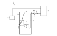
- FIG. 1 is a diagram showing an example of a security system.
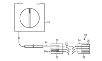
- 1 is a diagram illustrating an example of a disconnection inspection device in Embodiment 1.
- FIG. 1 is a diagram illustrating an example of a disconnection inspection device in Embodiment 1.
- FIG. 3 is a flowchart showing a disconnection inspection method in Embodiment 1.
- FIG. 3 is a diagram for explaining a disconnection inspection method.
- FIG. 3 is a diagram for explaining a disconnection inspection method.
- FIG. 3 is a diagram for explaining a disconnection inspection method. It is a figure showing other examples of a disconnection inspection device.
- FIG. 1 is a diagram showing an example of a security system 1. As shown in FIG. First, the security system 1 will be explained with reference to FIG. The security system 1 includes a door 2, an electric lock 3, a control device 4, and a reader 5.
- the door 2 is installed in a location where it is necessary to control traffic.
- the electric lock 3 is provided inside the door 2.
- An internal connector 7 is provided on the internal wiring 6 extending from the electric lock 3.
- An internal connector 8 is connected to the internal connector 7 .
- Internal connector 8 is provided at one end of internal wiring 9.
- the internal wiring 9 is arranged so as to extend from the inside of the door 2 to the inside of the wall adjacent to the door 2.
- One end side of the internal wiring 6 , internal connector 7 , internal connector 8 , and internal wiring 9 is arranged inside the door 2 .
- An internal connector 10 is provided at the other end of the internal wiring 9. That is, the internal wiring 9 connects the internal connector 8 and the internal connector 10.
- An internal connector 11 is connected to the internal connector 10 .
- Internal connector 11 is provided at one end of internal wiring 12 .
- Internal wiring 12 is connected to control device 4 .
- the reading device 5 reads identification information from the storage medium.
- the reading device 5 is a card reader.
- the storage medium is a tag built into a card such as an employee identification card.
- a user of the system holds his or her employee ID card over a card reader.
- the card reader reads identification information from the tag built into the employee card.
- the identification information read by the card reader is transmitted to the control device 4.
- the control device 4 controls the electric lock 3 and the reading device 5.
- the control device 4 is connected to the electric lock 3 via at least internal wiring 6 and internal wiring 9. Other internal connectors and other internal wiring may be present between the electric lock 3 and the control device 4.
- the control device 4 locks the door 2 with the electric lock 3 if the reading device 5 does not read the identification information.
- the control device 4 controls the electric lock 3 to unlock the door 2.
- the internal wiring 9 is bent every time the door 2 is opened or closed. Therefore, the internal wiring 9 is easily disconnected. If a disconnection occurs in the internal wiring 9, the electric lock 3 will not operate normally. When such a problem occurs, maintenance personnel go to the site and perform work to resolve the problem. In this work, first, a disconnection test is performed. Below, a description will be given of the disconnection inspection device 20 used by maintenance personnel to inspect for disconnections.
- the disconnection inspection device 20 includes a connector 21, an inspection terminal 22, and wiring 23.
- the connector 21 can be attached to and detached from the internal connector 8.
- connector 21 is the same type of connector as internal connector 7. That is, the connector 21 has the same shape as the internal connector 7.
- the connector 21 has a main body 24 and nine pins 25.
- the pin 25 is arranged inside the main body 24.
- the connector 21 includes pins 25, nine holes into which the pins 25 are inserted are formed in the internal connector 8 to which the connector 21 is connected.
- the inspection terminal 22 is a terminal to which the inspection terminal 14 of the circuit meter 13 is connected when inspecting for disconnection.
- the test terminal 22 is the same type of connector as the internal connector 8. That is, the testing terminal 22 has the same shape as the internal connector 8.
- the testing terminal 22 has a main body 26 in which nine holes 26a are formed.
- the test terminal 14 of the circuit meter 13 is a probe. When testing for disconnection, the test terminal 14 is inserted into the hole 26a.
- the wiring 23 connects the connector 21 and the test terminal 22.
- 2 and 3 show an example in which the wiring 23 has a line extending from the connector 21 and a line extending from the test terminal 22, and these lines are connected by crimping.
- FIG. 4 is a flowchart showing the disconnection inspection method in the first embodiment.
- 5 to 7 are diagrams for explaining the disconnection inspection method.
- the maintenance worker removes the electric lock 3 provided inside the door 2 from the door 2 (S101). Specifically, as shown in FIG. 5, a cover 15 is provided on the end surface 2a of the door 2. A maintenance person removes the cover 15 from the main body portion of the door 2. As a result, an opening 2b communicating with the space where the electric lock 3 is placed appears on the end surface 2a of the door 2. The maintenance worker removes the electric lock 3 by operating from the opening 2b, and then pulls the removed electric lock 3 out of the door 2 through the opening 2b.
- FIG. 6 shows a state in which the electric lock 3 is pulled out of the door 2.
- the internal wiring 6 extends from the electric lock 3. Further, an internal connector 8 is connected to an internal connector 7 provided on the internal wiring 6. Therefore, by pulling out the electric lock 3 out of the door 2 through the opening 2b, the internal connector 7 and the internal connector 8 are also pulled out out of the door 2 through the opening 2b, as shown in FIG. 6 (S102).
- FIG. 6 the state in which the internal connector 7 and the internal connector 8 are pulled out of the door 2 is shown by a solid line, and the state before being pulled out is shown by a broken line.
- the maintenance person attaches the disconnection inspection device 20 to the internal connector 8 from which the internal connector 7 has been removed. Specifically, the maintenance worker connects the connector 21 of the disconnection inspection device 20 to the internal connector 8 (S104). Next, the maintenance person connects the test terminal 14 of the circuit meter 13 to the test terminal 22 (S105). If the test terminal 14 is a probe, the maintenance person connects the test terminal 14 to the test terminal 22 by inserting the test terminal 14 into the hole 26a.
- FIG. 7 shows a state in which the test terminal 14 is electrically connected to the internal wiring 9. As shown in FIG. The maintenance personnel inspects for disconnection by opening and closing the door 2 in the state shown in FIG. 7 (S106).
- the occurrence of wire breakage may occur only when the door 2 makes a specific movement or when the door 2 is placed in a specific position. Therefore, in S106, the maintenance personnel determines whether there is a disconnection while moving the door 2. For example, a maintenance worker checks the resistance value displayed on the circuit meter 13 while moving the door 2 to confirm continuity between the test terminal 22 and the control device 4. While the circuit meter 13 detects continuity, the circuit meter 13 may emit a buzzer.
- the connector 21 when a disconnection test is performed, the connector 21 is connected to the internal connector 8 and the test terminal 14 is connected to the test terminal 22.
- the inspection terminal 14 When inspecting for disconnection, the inspection terminal 14 is not directly connected to the internal connector 8. Therefore, an accident in which a hole formed in the internal connector 8 is widened by the inspection terminal 14 during inspection does not occur.
- damage to the connector provided in the system 1 when inspecting for disconnection in the security system 1 provided with the electric lock 3, damage to the connector provided in the system 1 can be prevented.
- the circuit meter 13 may include a first fixing member for detachably fixing the main body portion to the door 2.
- the first fixing member is, for example, a magnet.
- the inspection terminal 22 of the disconnection inspection device 20 may further include a second fixing member for detachably fixing the main body 26 to the door 2.
- the second fixing member is, for example, a magnet.
- the maintenance personnel fixes the circuit meter 13 to the door 2 before inspecting for disconnection in S106. Then, the door 2 is moved with the circuit meter 13 fixed to the door 2, and the presence or absence of a disconnection is checked. The step of fixing the circuit meter 13 to the door 2 may be performed before S103. Moreover, when the test terminal 22 is equipped with the second fixing member, the maintenance staff may fix the test terminal 22 to the door 2 when fixing the circuit meter 13 to the door 2 .
- the testing terminal 22 may further include a holding member for holding the circuit meter 13.
- the holding member is a member for holding the circuit meter 13 on the main body 26 fixed to the door 2 by the second fixing member. If the test terminal 22 is equipped with the second fixing member and the holding member, even if the circuit meter 13 cannot be directly fixed to the door 2, maintenance personnel can fix the test terminal 22 to the door 2 and then , the circuit meter 13 can be held by the holding member.
- test terminal 22 is further provided with a holding mechanism for holding the test terminal 14 in a connected state. Also good.
- FIG. 8 is a diagram showing another example of the disconnection inspection device 20.
- the shape of the internal connector 8 provided in the security system 1 varies depending on the manufacturer.
- the disconnection inspection device 20 shown in FIG. 2 has one connector 21. Therefore, the disconnection inspection device 20 shown in FIG. 2 can only be connected to the internal connector 8 made by a specific manufacturer.
- FIG. 8 shows a disconnection inspection device 20 that is compatible with internal connectors 8 from a plurality of manufacturers.
- the disconnection inspection device 20 shown in FIG. 8 includes connectors 21A to 21C, an inspection terminal 22, and wirings 23A to 23C.
- the connector 21A is, for example, the same connector as the connector 21 shown in FIGS. 2 and 3.
- Connector 21A is attachable to and detachable from internal connector 8 manufactured by a particular manufacturer.
- the connector 21A is connected to the test terminal 22 by a wiring 23A. That is, the connector 21A and the test terminal 22 are connected by the wiring 23A.
- the connector 21B has a shape different from that of the connector 21A.
- the connector 21B can be attached to and detached from an internal connector 8 manufactured by another manufacturer.
- Connector 21B is connected to inspection terminal 22 by wiring 23B. That is, the connector 21B and the test terminal 22 are connected by the wiring 23B.
- the connector 21C has a shape different from that of the connector 21A and the shape of the connector 21B.
- the connector 21C can be attached to and detached from an internal connector 8 made by another manufacturer.
- the connector 21C is connected to the test terminal 22 by a wiring 23C. That is, the connector 21C and the test terminal 22 are connected by the wiring 23C.
- FIG. 8 shows an example in which each of the connectors 21A to 21C has nine pins numbered 1 to 9 (the pins are not shown).
- the inspection terminal 22 includes a magnet 27 as a second fixing member.
- nine holes 26a numbered 1 to 9 are formed in the main body 26.
- the wiring 23A extending from the No. 1 hole 26a is connected to the No. 1 pin provided on the connector 21A.
- the wiring 23B extending from the No. 1 hole 26a is connected to the No. 1 pin provided on the connector 21B.
- the wiring 23C extending from the No. 1 hole 26a is connected to the No. 1 pin provided on the connector 21C.
- the wiring 23B extending from the No. 9 hole 26a is connected to the No. 9 pin provided on the connector 21B.
- the wiring 23C extending from the No. 9 hole 26a is connected to the No. 9 pin provided on the connector 21C.
- the disconnection inspection device 20 shown in FIG. 8 can be applied to internal connectors 8 from multiple manufacturers.
- a circuit meter 13 equipped with a probe-type test terminal 14 is used to test for disconnection. That is, in the example shown in this embodiment, a hole 26a for inserting the test terminal 14 is formed in the main body 26 of the test terminal 22. As another example, a circuit meter 13 equipped with a clip-type test terminal 14 may be used to test for disconnection.
- the testing terminal 22 may be provided with a protrusion or a pin that can be held between the testing terminals 14.
- the inspection terminal 22 may include a protrusion, a pin, or the like.
- the disconnection inspection device is used when inspecting for disconnection in a security system equipped with an electric lock.
Landscapes
- Physics & Mathematics (AREA)
- General Physics & Mathematics (AREA)
- Testing Of Short-Circuits, Discontinuities, Leakage, Or Incorrect Line Connections (AREA)
- Alarm Systems (AREA)
Priority Applications (3)
| Application Number | Priority Date | Filing Date | Title |
|---|---|---|---|
| CN202280099451.8A CN119744356A (zh) | 2022-08-24 | 2022-08-24 | 断线检查装置和断线检查方法 |
| PCT/JP2022/031906 WO2024042646A1 (ja) | 2022-08-24 | 2022-08-24 | 断線検査装置及び断線検査方法 |
| JP2024542505A JP7831613B2 (ja) | 2022-08-24 | 2022-08-24 | 断線検査方法 |
Applications Claiming Priority (1)
| Application Number | Priority Date | Filing Date | Title |
|---|---|---|---|
| PCT/JP2022/031906 WO2024042646A1 (ja) | 2022-08-24 | 2022-08-24 | 断線検査装置及び断線検査方法 |
Publications (1)
| Publication Number | Publication Date |
|---|---|
| WO2024042646A1 true WO2024042646A1 (ja) | 2024-02-29 |
Family
ID=90012788
Family Applications (1)
| Application Number | Title | Priority Date | Filing Date |
|---|---|---|---|
| PCT/JP2022/031906 Ceased WO2024042646A1 (ja) | 2022-08-24 | 2022-08-24 | 断線検査装置及び断線検査方法 |
Country Status (3)
| Country | Link |
|---|---|
| JP (1) | JP7831613B2 (https=) |
| CN (1) | CN119744356A (https=) |
| WO (1) | WO2024042646A1 (https=) |
Citations (9)
| Publication number | Priority date | Publication date | Assignee | Title |
|---|---|---|---|---|
| JPH0247582U (https=) * | 1988-09-27 | 1990-03-30 | ||
| JPH0289166U (https=) * | 1988-08-26 | 1990-07-16 | ||
| JPH05141134A (ja) * | 1991-11-20 | 1993-06-08 | Sanwa Shutter Corp | 電気錠の異常チエツク装置 |
| JPH11217963A (ja) * | 1998-02-03 | 1999-08-10 | Mitsubishi Electric Building Techno Service Co Ltd | 電気錠動作チェッカー |
| US7112969B1 (en) * | 2006-02-17 | 2006-09-26 | Thomas Geoffrey L | Electrical interconnect interface and wire harness test and test development system and method |
| JP2010096742A (ja) * | 2008-09-16 | 2010-04-30 | Sumitomo Wiring Syst Ltd | 車両に搭載された電装システムのチェック装置 |
| JP2012107403A (ja) * | 2010-11-16 | 2012-06-07 | Seiwa Security System Co Ltd | 擬似電気錠 |
| JP3224921U (ja) * | 2019-11-18 | 2020-01-30 | 株式会社関電工 | テストリードアタッチメント |
| JP2020197424A (ja) * | 2019-05-31 | 2020-12-10 | 三菱電機ビルテクノサービス株式会社 | 接続アダプタ |
Family Cites Families (1)
| Publication number | Priority date | Publication date | Assignee | Title |
|---|---|---|---|---|
| JP7715058B2 (ja) | 2022-03-01 | 2025-07-30 | 三菱電機ビルソリューションズ株式会社 | 試験装置 |
-
2022
- 2022-08-24 JP JP2024542505A patent/JP7831613B2/ja active Active
- 2022-08-24 CN CN202280099451.8A patent/CN119744356A/zh active Pending
- 2022-08-24 WO PCT/JP2022/031906 patent/WO2024042646A1/ja not_active Ceased
Patent Citations (9)
| Publication number | Priority date | Publication date | Assignee | Title |
|---|---|---|---|---|
| JPH0289166U (https=) * | 1988-08-26 | 1990-07-16 | ||
| JPH0247582U (https=) * | 1988-09-27 | 1990-03-30 | ||
| JPH05141134A (ja) * | 1991-11-20 | 1993-06-08 | Sanwa Shutter Corp | 電気錠の異常チエツク装置 |
| JPH11217963A (ja) * | 1998-02-03 | 1999-08-10 | Mitsubishi Electric Building Techno Service Co Ltd | 電気錠動作チェッカー |
| US7112969B1 (en) * | 2006-02-17 | 2006-09-26 | Thomas Geoffrey L | Electrical interconnect interface and wire harness test and test development system and method |
| JP2010096742A (ja) * | 2008-09-16 | 2010-04-30 | Sumitomo Wiring Syst Ltd | 車両に搭載された電装システムのチェック装置 |
| JP2012107403A (ja) * | 2010-11-16 | 2012-06-07 | Seiwa Security System Co Ltd | 擬似電気錠 |
| JP2020197424A (ja) * | 2019-05-31 | 2020-12-10 | 三菱電機ビルテクノサービス株式会社 | 接続アダプタ |
| JP3224921U (ja) * | 2019-11-18 | 2020-01-30 | 株式会社関電工 | テストリードアタッチメント |
Also Published As
| Publication number | Publication date |
|---|---|
| JPWO2024042646A1 (https=) | 2024-02-29 |
| JP7831613B2 (ja) | 2026-03-17 |
| CN119744356A (zh) | 2025-04-01 |
Similar Documents
| Publication | Publication Date | Title |
|---|---|---|
| JP2608741B2 (ja) | 自動車に設置された複数の型式の電子制御システムの異常または故障を診断する装置 | |
| JPH08306750A (ja) | 半導体試験装置 | |
| KR102059633B1 (ko) | 특수 차량용 와이어링 하네스의 불량 검사 장치 및 방법 | |
| JP6317917B2 (ja) | 導通検査ユニット | |
| WO2024042646A1 (ja) | 断線検査装置及び断線検査方法 | |
| US8164474B2 (en) | Intelligent patching infastructure management system | |
| US7090531B2 (en) | Plug-connection verification for detecting a properly made electrical plug connection | |
| CN1126197C (zh) | 保证盲自动对接电气连接的完整性的装置和方法 | |
| KR20050109600A (ko) | 시험 장치 | |
| JPH10150082A (ja) | 半導体試験装置 | |
| JP7715058B2 (ja) | 試験装置 | |
| Ke | Backplane interconnect test in a boundary-scan environment | |
| JP7816549B2 (ja) | セキュリティシステムの点検器具 | |
| KR0143536B1 (ko) | 전력선 반송 보호 계전 시스템에서의 고장 진단방법 및 장치 | |
| CN109283920B (zh) | 一种dcs系统连接故障的测试装置和一种测试方法 | |
| JP4999630B2 (ja) | 車載用の故障診断装置 | |
| KR102919271B1 (ko) | 케이블 결선 상태 자동 점검 장치 및 방법 | |
| CN101385652B (zh) | 医疗设备以及医疗设备的检查方法 | |
| JPH05297051A (ja) | コネクタ接続信号線状態確認装置 | |
| JPH10227822A (ja) | 活線状態での芯線対照照査器 | |
| CN203387020U (zh) | Bmw与mini专用12芯跨接适配器导线组件 | |
| JPH1054861A (ja) | ワイヤーハーネスの導通検査方法 | |
| JPS63117608A (ja) | 配電盤の管理方法および配電盤管理用鍵 | |
| SU943609A1 (ru) | Устройство дл испытани кабелей | |
| CN118518327A (zh) | 自行车锁自动化测试系统 |
Legal Events
| Date | Code | Title | Description |
|---|---|---|---|
| 121 | Ep: the epo has been informed by wipo that ep was designated in this application |
Ref document number: 22956474 Country of ref document: EP Kind code of ref document: A1 |
|
| WWE | Wipo information: entry into national phase |
Ref document number: 2024542505 Country of ref document: JP |
|
| WWE | Wipo information: entry into national phase |
Ref document number: 202280099451.8 Country of ref document: CN |
|
| NENP | Non-entry into the national phase |
Ref country code: DE |
|
| WWP | Wipo information: published in national office |
Ref document number: 202280099451.8 Country of ref document: CN |
|
| 122 | Ep: pct application non-entry in european phase |
Ref document number: 22956474 Country of ref document: EP Kind code of ref document: A1 |