WO2024034636A1 - 光ファイバの曲げ損失測定方法 - Google Patents
光ファイバの曲げ損失測定方法 Download PDFInfo
- Publication number
- WO2024034636A1 WO2024034636A1 PCT/JP2023/029089 JP2023029089W WO2024034636A1 WO 2024034636 A1 WO2024034636 A1 WO 2024034636A1 JP 2023029089 W JP2023029089 W JP 2023029089W WO 2024034636 A1 WO2024034636 A1 WO 2024034636A1
- Authority
- WO
- WIPO (PCT)
- Prior art keywords
- optical fiber
- bending loss
- turns
- loss value
- transmission wavelength
- Prior art date
- Legal status (The legal status is an assumption and is not a legal conclusion. Google has not performed a legal analysis and makes no representation as to the accuracy of the status listed.)
- Ceased
Links
Images



Classifications
-
- G—PHYSICS
- G01—MEASURING; TESTING
- G01M—TESTING STATIC OR DYNAMIC BALANCE OF MACHINES OR STRUCTURES; TESTING OF STRUCTURES OR APPARATUS, NOT OTHERWISE PROVIDED FOR
- G01M11/00—Testing of optical apparatus; Testing structures by optical methods not otherwise provided for
-
- G—PHYSICS
- G01—MEASURING; TESTING
- G01M—TESTING STATIC OR DYNAMIC BALANCE OF MACHINES OR STRUCTURES; TESTING OF STRUCTURES OR APPARATUS, NOT OTHERWISE PROVIDED FOR
- G01M11/00—Testing of optical apparatus; Testing structures by optical methods not otherwise provided for
- G01M11/30—Testing of optical devices, constituted by fibre optics or optical waveguides
- G01M11/33—Testing of optical devices, constituted by fibre optics or optical waveguides with a light emitter being disposed at one fibre or waveguide end-face, and a light receiver at the other end-face
- G01M11/335—Testing of optical devices, constituted by fibre optics or optical waveguides with a light emitter being disposed at one fibre or waveguide end-face, and a light receiver at the other end-face using two or more input wavelengths
-
- G—PHYSICS
- G01—MEASURING; TESTING
- G01M—TESTING STATIC OR DYNAMIC BALANCE OF MACHINES OR STRUCTURES; TESTING OF STRUCTURES OR APPARATUS, NOT OTHERWISE PROVIDED FOR
- G01M11/00—Testing of optical apparatus; Testing structures by optical methods not otherwise provided for
- G01M11/08—Testing mechanical properties
- G01M11/088—Testing mechanical properties of optical fibres; Mechanical features associated with the optical testing of optical fibres
Definitions
- the present disclosure relates to a method for measuring bending loss of an optical fiber.
- Patent Document 1 discloses a method for measuring bending loss of an optical fiber.
- the bending loss of an optical fiber is measured by taking the difference between the transmitted light power when the optical fiber is not bent and the transmitted light power when the optical fiber is bent.
- the optical fiber bending loss measurement method of the present disclosure includes: A method for measuring bending loss of a resin-coated optical fiber, the method comprising: A reference winding number at which the wavelength dependence of the bending loss value of the optical fiber in a region below a predetermined transmission wavelength has an exponential shape with respect to the transmission wavelength when the optical fiber is wound around a mandrel having a predetermined diameter.
- the first step is to decide the Injecting light of a predetermined power at the predetermined transmission wavelength into the first end of the optical fiber with the mandrel wound at the reference number of turns, and measuring the power of the light emitted from the second end of the optical fiber.
- a second step of Light having the predetermined power and the predetermined transmission wavelength is incident on the first end of the optical fiber while being wound around the mandrel with a number of turns greater than the reference number of turns, and is emitted from the second end of the optical fiber.
- FIG. 1 is a diagram showing the flow of a method for measuring bending loss of an optical fiber according to this embodiment.
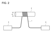
- FIG. 2 is a diagram for explaining a method of measuring the transmission loss value of an optical fiber.
- FIG. 3 is a graph showing the wavelength dependence of the transmission loss value of an optical fiber.
- FIG. 4 is a graph showing the wavelength dependence of the bending loss value of an optical fiber.
- the purpose of the present disclosure is to more accurately measure the bending loss of an optical fiber.
- the optical fiber bending loss measurement method of the present disclosure includes: (1) A method for measuring bending loss of a resin-coated optical fiber, comprising: A reference winding number at which the wavelength dependence of the bending loss value of the optical fiber in a region below a predetermined transmission wavelength has an exponential shape with respect to the transmission wavelength when the optical fiber is wound around a mandrel having a predetermined diameter.
- the first step is to decide the Injecting light of a predetermined power at the predetermined transmission wavelength into the first end of the optical fiber with the mandrel wound at the reference number of turns, and measuring the power of the light emitted from the second end of the optical fiber.
- a second step of Light having the predetermined power and the predetermined transmission wavelength is incident on the first end of the optical fiber while being wound around the mandrel with a number of turns greater than the reference number of turns, and is emitted from the second end of the optical fiber.
- the bending loss of the optical fiber is calculated based on the power of two transmitted lights that are not affected by the whispering gallery mode light. Thereby, the bending loss value of the optical fiber can be determined more accurately.
- the optical fiber is wound around a mandrel having the predetermined diameter, and the wavelength dependence of the bending loss value of the optical fiber in a region below the predetermined transmission wavelength is determined with respect to the transmission wavelength.
- the number of turns of the optical fiber having an exponential function shape may be determined by using the optical fiber, and the determined number of turns of the optical fiber may be used as the reference number of turns in the first step.
- the reference number of turns is set using the optical fiber to be measured, it is possible to obtain a bending loss value that is not affected by whispering gallery mode light.
- the bending loss value per turn of the optical fiber determined from the bending loss value determined in the fourth step is the bending loss of the standard optical fiber at the predetermined transmission wavelength. If the bending loss value is smaller than the bending loss value per turn of the standard optical fiber calculated from the value, the optical fiber may be used as the standard optical fiber.
- the reference number of turns is calculated again based on the optical fiber that is stronger in bending, so it is possible to obtain a bending loss value that is not affected by whispering gallery mode light.
- FIG. 1 is a diagram showing the flow of a method for measuring bending loss of an optical fiber 1 according to the present embodiment.
- FIG. 2 is a diagram for explaining a method of measuring the power of light that is input from one end (first end) of the optical fiber 1 and output from the other end (second end).
- the optical fiber 1 to be measured has a core and a cladding made of glass, and the periphery of the cladding is covered with a coating layer made of resin.
- the reference number of turns T1 of the optical fiber 1 to be wound around the mandrel 2 is determined (STEP 1).
- the reference number of turns T1 is the number of turns used as a reference for determining the bending loss value of the optical fiber 1.
- the reference number of turns T1 is set to a number of turns at which the wavelength dependence of the bending loss value of the optical fiber 1 in a region below a predetermined transmission wavelength is not affected by whispering gallery mode light.
- the predetermined transmission wavelength is, for example, 1550 nm or 1625 nm.
- the reference winding number T1 is such that when the optical fiber 1 is wound around the mandrel 2, the wavelength dependence of the bending loss value of the optical fiber 1 in a region below a predetermined transmission wavelength is an index with respect to the transmission wavelength.
- the number of turns is set to give the function shape.
- the expression "not affected by whispering gallery mode light” is not limited to a state where the influence of whispering gallery mode light is not affected at all, but also a state where the influence of whispering gallery mode light is small enough to be ignored. include.
- the standard number of turns T1 may be calculated each time the bending loss value of the optical fiber 1 is determined.
- light of a predetermined power is inputted from the light source 3 into one end of the optical fiber 1, and is emitted from the other end of the optical fiber 1.
- the power of the transmitted light (hereinafter referred to as transmitted light power P0) is measured by the power meter 4. This measurement is performed using light of each wavelength ( ⁇ ) below a predetermined transmission wavelength, and the transmitted light power (P0( ⁇ )) for each wavelength ( ⁇ ) is obtained.
- the optical power P1 is measured by a power meter 4. This measurement is performed using light of each wavelength ( ⁇ ) below a predetermined transmission wavelength, and the transmitted light power (P1( ⁇ )) for each wavelength ( ⁇ ) is obtained.
- the optical fiber 1 is Find the wavelength dependence of the bending loss value. If the wavelength dependence of the determined bending loss value has an exponential shape with respect to the transmission wavelength, the number of turns of the optical fiber 1 on the mandrel 2 at this time is set as the reference number of turns T1.
- transmitted light power P10 The power (hereinafter referred to as transmitted light power P10) is measured by the power meter 4 (STEP 2).
- the mandrel 2 is wound with the number of turns T2
- light of a predetermined transmission wavelength and a predetermined power is inputted from the light source 3 into one end of the optical fiber 1, and the power of the light emitted from the other end of the optical fiber 1 is determined.
- transmitted light power P11 is measured by the power meter 4 (STEP 3).
- the number of turns T2 is set to be greater than the reference number of turns T1.
- the bending loss value of the optical fiber 1 at a predetermined transmission wavelength when the optical fiber 1 is bent at a predetermined diameter D is calculated.
- the bending loss of the optical fiber 1 is caused by a portion of the core mode light leaking into the cladding at the bent portion of the optical fiber 1.
- a part of the light leaking into the cladding (whispering gallery mode light) is Fresnel-reflected at the interface between the cladding layer and the air and recombined with the core mode light, and during this recombination, the core mode light and whispering Interference with gallery mode light occurs.
- This interference produces oscillating components at constant optical frequency intervals in the transmission spectrum of the bent optical fiber, making it difficult to accurately measure bending loss.
- the bending diameter of the optical fiber 1 becomes smaller, the generation of whispering gallery mode light becomes more pronounced. Therefore, when the bending diameter of the optical fiber 1 is small, it is difficult to accurately measure the bending loss.
- whispering gallery mode light has the property of becoming less likely to occur by increasing the number of times the optical fiber 1 is wound around the mandrel 2. Therefore, in the optical fiber bending loss measuring method of the present embodiment, the transmitted light power P10 at a predetermined transmission wavelength of the optical fiber 1 wound with the reference number of turns T1 in which the generation of whispering gallery mode light is small is used as a reference. Then, based on the transmitted light power P10 and the transmitted light power P11 at a predetermined transmission wavelength of the optical fiber 1 wound with the number of turns T2 larger than the reference number of turns T1, the optical fiber 1 is bent at a predetermined transmission wavelength. Calculating loss value.
- the bending loss value at a predetermined transmission wavelength of the optical fiber 1 is calculated based on two transmitted light powers P10 and P11 that are not affected by the whispering gallery mode light. Thereby, the bending loss of the optical fiber 1 can be measured more accurately.
- the standard number of turns T1 is calculated each time the bending loss value of the optical fiber 1 is calculated.
- the standard number of turns T1 may not be calculated every time the bending loss value of the optical fiber 1 is calculated, but may be set in advance.
- the reference number of turns T1 may be determined using a standard optical fiber separately from the optical fiber to be measured. Specifically, a standard optical fiber is wound around a mandrel 2 having a predetermined diameter D, and the bending loss value of the standard optical fiber in a region below a predetermined transmission wavelength is determined. Note that the mandrel 2 may be a mandrel used to determine the bending loss value of the optical fiber 1, or may be a different mandrel having a predetermined diameter D. Then, the number of turns at which the wavelength dependence of the determined bending loss value of the standard optical fiber has an exponential function shape with respect to the transmission wavelength is set as the reference number of turns T1. Note that the term "standard optical fiber" means an optical fiber that serves as a reference for setting the reference number of turns T1. For example, as the standard optical fiber, the same type of optical fiber as the optical fiber to be measured is used.
- the standard number of turns used in past bending loss measurements may be used as the standard number of turns T1.
- the optical fiber used when calculating the standard number of turns in the past bending loss measurement becomes the standard optical fiber used to set the reference number of turns T1.
- the bending loss value per number of turns of the optical fiber obtained from the bending loss value obtained in STEP 4 is determined from the bending loss value of the standard optical fiber at the predetermined transmission wavelength. If the bending loss value is smaller than the determined bending loss value per 1 turn of the standard optical fiber, the reference number of turns T1 may be reset based on 1 optical fiber. That is, the optical fiber 1 is used as a standard optical fiber, and the number of turns at which the bending loss value of the transmission loss value of the optical fiber 1 in a region below a predetermined transmission wavelength has an exponential shape with respect to the transmission wavelength is determined. The number of turns may be used as the reference number of turns T1. As a result, the reference number of turns T1 is recalculated based on the optical fiber 1 that is stronger in bending, so it is possible to obtain a bending loss value that is not affected by whispering gallery mode light.
- the standard optical fiber when calculating the bending loss value per turn of the standard optical fiber obtained from the bending loss value of the standard optical fiber at a predetermined transmission wavelength, the standard optical fiber is wound around the mandrel 2 with the standard number of turns T1.
- the wavelength dependence of the bending loss value on the number of turns of the optical fiber 1 was evaluated. Specifically, using a mandrel 2 with a diameter of 30 mm, the number of turns T of the optical fiber 1 wound around the mandrel 2 is changed, the wavelength of the light incident on the light source 3 is changed, and the optical fiber of each number of turns is changed. The bending loss value of 1 was measured. The number of turns T was changed every two turns between 2 turns (2T) and 20 turns (20T). The results are shown in FIG.
- FIG. 4 shows the wavelength dependence of the bending loss value of the optical fiber 1 calculated based on the bending loss value of the optical fiber 1 calculated in FIG. Specifically, the bending loss value of the optical fiber 1 was calculated based on the difference between two bending loss values having different numbers of turns by two turns.
- the bending loss value calculated from the difference between the bending loss value when the number of turns T is 4 turns (4T) and the bending loss value when the number of turns T is 2 turns (2T) ( It was found that the wavelength dependence of the exponential function shape was not maintained for the value indicated by the index of 4T-2T. This is considered to be because the number of turns T is small and the bending loss value is influenced by whispering gallery mode light.
- the bending loss value calculated from the difference between the bending loss value when the number of turns T is 20 turns (20T) and the bending loss value when the number of turns T is 18 turns (18T) (based on the index 20T-18T in the figure) It was found that the wavelength dependence of the exponential function shape was maintained for the values shown. This is considered to be because the number of turns T is large and the bending loss value is not affected by whispering gallery mode light.
- the bending loss value of the optical fiber 1 is calculated based on two bending loss values obtained for the optical fibers 1 whose number of turns differs by two turns.
- the bending loss value of the optical fiber 1 may be calculated from two bending loss values obtained for the optical fibers 1 whose number of turns differs by one turn or by three or more turns.
- Optical fiber 2 Mandrel 3: Light source 4: Power meter P0: Power of incident light P1: Power of emitted light
Landscapes
- Physics & Mathematics (AREA)
- Chemical & Material Sciences (AREA)
- Analytical Chemistry (AREA)
- General Physics & Mathematics (AREA)
- Optics & Photonics (AREA)
- Testing Of Optical Devices Or Fibers (AREA)
- Investigating Strength Of Materials By Application Of Mechanical Stress (AREA)
Abstract
Description
樹脂被覆された光ファイバの曲げ損失を測定する方法であって、
所定の直径を有するマンドレルに前記光ファイバを巻いた時の、所定の伝送波長以下の領域における前記光ファイバの曲げ損失値の波長依存性が、伝送波長に対して指数関数形状となる基準巻き数を決める第一工程と、
前記マンドレルに前記基準巻き数で巻いた状態で前記光ファイバの第一端に前記所定の伝送波長で所定パワーの光を入射させ、前記光ファイバの第二端から出射される光のパワーを測定する第二工程と、
前記マンドレルに前記基準巻き数より多い巻き数で巻いた状態で前記光ファイバの前記第一端に前記所定の伝送波長で前記所定パワーの光を入射させ、前記光ファイバの前記第二端から出射される光のパワーを測定する第三工程と、
前記第二工程で測定した光のパワーと前記第三工程で測定した光のパワーとに基づいて、前記所定の直径で前記光ファイバを曲げたときの前記光ファイバの前記所定の伝送波長における曲げ損失値を求める第四工程と、を備えている。
光ファイバの曲げ部分においてコアからクラッドに漏れた光(ウィスパリングギャラリーモード光)の一部が被覆層と空気との界面でフレネル反射されてコアモード光と再結合すると、コアモード光とウィスパリングギャラリーモード光との干渉が生じ、光ファイバの曲げ損失を正確に測定することが困難となる。
本開示によれば、光ファイバの曲げ損失をより正確に測定できる。
最初に本開示の実施形態の内容を列記して説明する。
本開示の光ファイバの曲げ損失測定方法は、
(1)樹脂被覆された光ファイバの曲げ損失を測定する方法であって、
所定の直径を有するマンドレルに前記光ファイバを巻いた時の、所定の伝送波長以下の領域における前記光ファイバの曲げ損失値の波長依存性が、伝送波長に対して指数関数形状となる基準巻き数を決める第一工程と、
前記マンドレルに前記基準巻き数で巻いた状態で前記光ファイバの第一端に前記所定の伝送波長で所定パワーの光を入射させ、前記光ファイバの第二端から出射される光のパワーを測定する第二工程と、
前記マンドレルに前記基準巻き数より多い巻き数で巻いた状態で前記光ファイバの前記第一端に前記所定の伝送波長で前記所定パワーの光を入射させ、前記光ファイバの前記第二端から出射される光のパワーを測定する第三工程と、
前記第二工程で測定した光のパワーと前記第三工程で測定した光のパワーとに基づいて、前記所定の直径で前記光ファイバを曲げたときの前記光ファイバの前記所定の伝送波長における曲げ損失値を求める第四工程と、を備えている。
本開示の実施形態に係る光ファイバの曲げ損失測定方法の具体例を、以下に図面を参照しつつ説明する。なお、本発明はこれらの例示に限定されるものではなく、請求の範囲によって示され、請求の範囲と均等の意味および範囲内でのすべての変更が含まれることが意図される。
以下、実施例を示して本開示を更に具体的に説明する。本開示は以下の実施例によって何ら限定されるものではない。
2:マンドレル
3:光源
4:パワーメータ
P0:入射された光のパワー
P1:出射された光のパワー
Claims (4)
- 樹脂被覆された光ファイバの曲げ損失を測定する方法であって、
所定の直径を有するマンドレルに前記光ファイバを巻いた時の、所定の伝送波長以下の領域における前記光ファイバの曲げ損失値の波長依存性が、伝送波長に対して指数関数形状となる基準巻き数を決める第一工程と、
前記マンドレルに前記基準巻き数で巻いた状態で前記光ファイバの第一端に前記所定の伝送波長で所定パワーの光を入射させ、前記光ファイバの第二端から出射される光のパワーを測定する第二工程と、
前記マンドレルに前記基準巻き数より多い巻き数で巻いた状態で前記光ファイバの前記第一端に前記所定の伝送波長で前記所定パワーの光を入射させ、前記光ファイバの前記第二端から出射される光のパワーを測定する第三工程と、
前記第二工程で測定した光のパワーと前記第三工程で測定した光のパワーとに基づいて、前記所定の直径で前記光ファイバを曲げたときの前記光ファイバの前記所定の伝送波長における曲げ損失値を求める第四工程と、を備えている、光ファイバの曲げ損失測定方法。 - 前記所定の直径を有するマンドレルに前記光ファイバを巻き付け、前記所定の伝送波長以下の領域における前記光ファイバの曲げ損失値の波長依存性が、伝送波長に対して指数関数形状となる巻き数を求め、求めた前記光ファイバの巻き数を、前記第一工程の前記基準巻き数として用いる、請求項1に記載の光ファイバの曲げ損失測定方法。
- 標準光ファイバを用意して前記所定の直径を有するマンドレルに前記標準光ファイバを巻き付け、前記所定の伝送波長以下の領域における前記標準光ファイバの曲げ損失値の波長依存性が、伝送波長に対して指数関数形状となる巻き数を求め、求めた前記標準光ファイバの巻き数を、前記第一工程の前記基準巻き数として用いる、請求項1に記載の光ファイバの曲げ損失測定方法。
- 前記第四工程で求めた曲げ損失値から求めた前記光ファイバの巻き数1あたりの曲げ損失値が、前記所定の伝送波長における前記標準光ファイバの曲げ損失値から求めた前記標準光ファイバの巻き数1あたりの曲げ損失値より小さい場合は、前記光ファイバを前記標準光ファイバとする、請求項3に記載の光ファイバの曲げ損失測定方法。
Priority Applications (4)
| Application Number | Priority Date | Filing Date | Title |
|---|---|---|---|
| CN202380055666.4A CN119585596A (zh) | 2022-08-12 | 2023-08-09 | 光纤的弯曲损耗测定方法 |
| GB2500181.9A GB2634698A (en) | 2022-08-12 | 2023-08-09 | Optical fiber bending loss measuring method |
| US18/836,511 US20250164347A1 (en) | 2022-08-12 | 2023-08-09 | Optical fiber bending loss measuring method |
| JP2024540507A JPWO2024034636A1 (ja) | 2022-08-12 | 2023-08-09 |
Applications Claiming Priority (2)
| Application Number | Priority Date | Filing Date | Title |
|---|---|---|---|
| JP2022128675 | 2022-08-12 | ||
| JP2022-128675 | 2022-08-12 |
Publications (1)
| Publication Number | Publication Date |
|---|---|
| WO2024034636A1 true WO2024034636A1 (ja) | 2024-02-15 |
Family
ID=89851649
Family Applications (1)
| Application Number | Title | Priority Date | Filing Date |
|---|---|---|---|
| PCT/JP2023/029089 Ceased WO2024034636A1 (ja) | 2022-08-12 | 2023-08-09 | 光ファイバの曲げ損失測定方法 |
Country Status (5)
| Country | Link |
|---|---|
| US (1) | US20250164347A1 (ja) |
| JP (1) | JPWO2024034636A1 (ja) |
| CN (1) | CN119585596A (ja) |
| GB (1) | GB2634698A (ja) |
| WO (1) | WO2024034636A1 (ja) |
Citations (6)
| Publication number | Priority date | Publication date | Assignee | Title |
|---|---|---|---|---|
| JPH06288865A (ja) * | 1993-04-02 | 1994-10-18 | Showa Electric Wire & Cable Co Ltd | 光ファイバ損失測定器 |
| JP2005181664A (ja) * | 2003-12-19 | 2005-07-07 | Furukawa Electric Co Ltd:The | 光ファイバ及びこの光ファイバを用いたリボンスロット型光ファイバケーブル |
| JP2007057328A (ja) * | 2005-08-23 | 2007-03-08 | Sumitomo Electric Ind Ltd | 光ファイバの判定方法、光ファイバの損失波長特性評価方法及び光ファイバの出荷方法 |
| JP2012194004A (ja) * | 2011-03-15 | 2012-10-11 | Sumitomo Electric Ind Ltd | 光ファイバ特性測定方法 |
| US20140205250A1 (en) * | 2006-12-13 | 2014-07-24 | Coming Cable Systems Llc | Fiber optic cables and assemblies and the performance thereof |
| WO2021251473A1 (ja) * | 2020-06-12 | 2021-12-16 | 住友電気工業株式会社 | 曲げ損失測定用の曲げ付与装置、曲げ試験装置 |
Family Cites Families (3)
| Publication number | Priority date | Publication date | Assignee | Title |
|---|---|---|---|---|
| JPH0422054Y2 (ja) * | 1985-11-22 | 1992-05-20 | ||
| EP1657575A4 (en) * | 2003-04-11 | 2008-03-19 | Fujikura Ltd | OPTICAL FIBER |
| JP4219798B2 (ja) * | 2003-12-18 | 2009-02-04 | 大日本スクリーン製造株式会社 | 基板処理装置 |
-
2023
- 2023-08-09 GB GB2500181.9A patent/GB2634698A/en active Pending
- 2023-08-09 CN CN202380055666.4A patent/CN119585596A/zh active Pending
- 2023-08-09 JP JP2024540507A patent/JPWO2024034636A1/ja active Pending
- 2023-08-09 WO PCT/JP2023/029089 patent/WO2024034636A1/ja not_active Ceased
- 2023-08-09 US US18/836,511 patent/US20250164347A1/en active Pending
Patent Citations (6)
| Publication number | Priority date | Publication date | Assignee | Title |
|---|---|---|---|---|
| JPH06288865A (ja) * | 1993-04-02 | 1994-10-18 | Showa Electric Wire & Cable Co Ltd | 光ファイバ損失測定器 |
| JP2005181664A (ja) * | 2003-12-19 | 2005-07-07 | Furukawa Electric Co Ltd:The | 光ファイバ及びこの光ファイバを用いたリボンスロット型光ファイバケーブル |
| JP2007057328A (ja) * | 2005-08-23 | 2007-03-08 | Sumitomo Electric Ind Ltd | 光ファイバの判定方法、光ファイバの損失波長特性評価方法及び光ファイバの出荷方法 |
| US20140205250A1 (en) * | 2006-12-13 | 2014-07-24 | Coming Cable Systems Llc | Fiber optic cables and assemblies and the performance thereof |
| JP2012194004A (ja) * | 2011-03-15 | 2012-10-11 | Sumitomo Electric Ind Ltd | 光ファイバ特性測定方法 |
| WO2021251473A1 (ja) * | 2020-06-12 | 2021-12-16 | 住友電気工業株式会社 | 曲げ損失測定用の曲げ付与装置、曲げ試験装置 |
Also Published As
| Publication number | Publication date |
|---|---|
| JPWO2024034636A1 (ja) | 2024-02-15 |
| US20250164347A1 (en) | 2025-05-22 |
| CN119585596A (zh) | 2025-03-07 |
| GB202500181D0 (en) | 2025-02-19 |
| GB2634698A (en) | 2025-04-16 |
Similar Documents
| Publication | Publication Date | Title |
|---|---|---|
| CN101625437B (zh) | 多模光纤 | |
| KR101597613B1 (ko) | 자가보상형 멀티모드 섬유 | |
| JP2012098722A (ja) | 曲げ損失の影響を受けないマルチモード光ファイバ | |
| JP3964442B2 (ja) | マルチモード光ファイバ伝送路におけるモード分散の補償方法 | |
| CN106605135B (zh) | 评价多模光纤的emb的方法和选择高emb多模光纤的方法 | |
| US20100247093A1 (en) | Cutoff wavelength measuring method and optical communication system | |
| US20120236295A1 (en) | Method of measuring bending performance of optical fiber | |
| JP6363703B2 (ja) | 漏洩モードの影響を抑えた曲げに強い多モード光ファイバ | |
| WO2024034636A1 (ja) | 光ファイバの曲げ損失測定方法 | |
| US8508724B2 (en) | Method of measuring cutoff wavelength | |
| US8896822B2 (en) | Method of measuring cut-off wavelength of optical fiber | |
| JP5365338B2 (ja) | カットオフ波長測定方法および光通信システム | |
| JP2008209603A (ja) | 光ファイバ | |
| US7035514B2 (en) | Glass base material, optical fiber, method for manufacturing thereof, and method for determining cause of defect thereof | |
| US6739154B2 (en) | Method for manufacturing optical gratings | |
| JP7006964B2 (ja) | 光ファイバ式計測装置及び光ファイバ式計測方法 | |
| JP5137640B2 (ja) | 光ファイバの光学特性測定方法 | |
| JPH03144337A (ja) | 光ファイバの特性測定方法 | |
| US9753216B2 (en) | Multimode optical fiber and optical cable including the same | |
| JP6402482B2 (ja) | 光ファイバのカットオフ波長測定方法 | |
| JP5350841B2 (ja) | 光ファイバコード評価方法及び装置 | |
| JP2003167137A (ja) | スラント型短周期光ファイバグレーティング及びその製造方法 | |
| CN111366180A (zh) | 一种基于光纤传感器的外界参数测量方法 | |
| JP2010032272A (ja) | 活線検出装置 | |
| JPS63214638A (ja) | 光フアイバコア径測定方法 |
Legal Events
| Date | Code | Title | Description |
|---|---|---|---|
| 121 | Ep: the epo has been informed by wipo that ep was designated in this application |
Ref document number: 23852598 Country of ref document: EP Kind code of ref document: A1 |
|
| ENP | Entry into the national phase |
Ref document number: 2024540507 Country of ref document: JP Kind code of ref document: A |
|
| WWE | Wipo information: entry into national phase |
Ref document number: 18836511 Country of ref document: US |
|
| ENP | Entry into the national phase |
Ref document number: 202500181 Country of ref document: GB Kind code of ref document: A Free format text: PCT FILING DATE = 20230809 |
|
| WWE | Wipo information: entry into national phase |
Ref document number: 2500181.9 Country of ref document: GB |
|
| WWE | Wipo information: entry into national phase |
Ref document number: 202380055666.4 Country of ref document: CN |
|
| WWP | Wipo information: published in national office |
Ref document number: 202380055666.4 Country of ref document: CN |
|
| NENP | Non-entry into the national phase |
Ref country code: DE |
|
| WWP | Wipo information: published in national office |
Ref document number: 2500181.9 Country of ref document: GB |
|
| WWP | Wipo information: published in national office |
Ref document number: 18836511 Country of ref document: US |
|
| 122 | Ep: pct application non-entry in european phase |
Ref document number: 23852598 Country of ref document: EP Kind code of ref document: A1 |