WO2024029587A1 - 車両用シート - Google Patents
車両用シート Download PDFInfo
- Publication number
- WO2024029587A1 WO2024029587A1 PCT/JP2023/028373 JP2023028373W WO2024029587A1 WO 2024029587 A1 WO2024029587 A1 WO 2024029587A1 JP 2023028373 W JP2023028373 W JP 2023028373W WO 2024029587 A1 WO2024029587 A1 WO 2024029587A1
- Authority
- WO
- WIPO (PCT)
- Prior art keywords
- engagement member
- guide member
- hanging
- seat
- clip
- Prior art date
- Legal status (The legal status is an assumption and is not a legal conclusion. Google has not performed a legal analysis and makes no representation as to the accuracy of the status listed.)
- Ceased
Links
Images




Classifications
-
- B—PERFORMING OPERATIONS; TRANSPORTING
- B60—VEHICLES IN GENERAL
- B60R—VEHICLES, VEHICLE FITTINGS, OR VEHICLE PARTS, NOT OTHERWISE PROVIDED FOR
- B60R21/00—Arrangements or fittings on vehicles for protecting or preventing injuries to occupants or pedestrians in case of accidents or other traffic risks
- B60R21/02—Occupant safety arrangements or fittings, e.g. crash pads
- B60R21/16—Inflatable occupant restraints or confinements designed to inflate upon impact or impending impact, e.g. air bags
- B60R21/20—Arrangements for storing inflatable members in their non-use or deflated condition; Arrangement or mounting of air bag modules or components
- B60R21/207—Arrangements for storing inflatable members in their non-use or deflated condition; Arrangement or mounting of air bag modules or components in vehicle seats
-
- B—PERFORMING OPERATIONS; TRANSPORTING
- B60—VEHICLES IN GENERAL
- B60N—SEATS SPECIALLY ADAPTED FOR VEHICLES; VEHICLE PASSENGER ACCOMMODATION NOT OTHERWISE PROVIDED FOR
- B60N2/00—Seats specially adapted for vehicles; Arrangement or mounting of seats in vehicles
- B60N2/58—Seat coverings
-
- A—HUMAN NECESSITIES
- A47—FURNITURE; DOMESTIC ARTICLES OR APPLIANCES; COFFEE MILLS; SPICE MILLS; SUCTION CLEANERS IN GENERAL
- A47C—CHAIRS; SOFAS; BEDS
- A47C31/00—Details or accessories for chairs, beds, or the like, not provided for in other groups of this subclass, e.g. upholstery fasteners, mattress protectors, stretching devices for mattress nets
- A47C31/02—Upholstery attaching means
-
- B—PERFORMING OPERATIONS; TRANSPORTING
- B60—VEHICLES IN GENERAL
- B60N—SEATS SPECIALLY ADAPTED FOR VEHICLES; VEHICLE PASSENGER ACCOMMODATION NOT OTHERWISE PROVIDED FOR
- B60N2/00—Seats specially adapted for vehicles; Arrangement or mounting of seats in vehicles
- B60N2/24—Seats specially adapted for vehicles; Arrangement or mounting of seats in vehicles for particular purposes or particular vehicles
- B60N2/42—Seats specially adapted for vehicles; Arrangement or mounting of seats in vehicles for particular purposes or particular vehicles the seat constructed to protect the occupant from the effect of abnormal g-forces, e.g. crash or safety seats
-
- B—PERFORMING OPERATIONS; TRANSPORTING
- B60—VEHICLES IN GENERAL
- B60N—SEATS SPECIALLY ADAPTED FOR VEHICLES; VEHICLE PASSENGER ACCOMMODATION NOT OTHERWISE PROVIDED FOR
- B60N2/00—Seats specially adapted for vehicles; Arrangement or mounting of seats in vehicles
- B60N2/58—Seat coverings
- B60N2/5816—Seat coverings attachments thereof
- B60N2/5825—Seat coverings attachments thereof by hooks, staples, clips, snap fasteners or the like
-
- B—PERFORMING OPERATIONS; TRANSPORTING
- B60—VEHICLES IN GENERAL
- B60R—VEHICLES, VEHICLE FITTINGS, OR VEHICLE PARTS, NOT OTHERWISE PROVIDED FOR
- B60R21/00—Arrangements or fittings on vehicles for protecting or preventing injuries to occupants or pedestrians in case of accidents or other traffic risks
- B60R21/02—Occupant safety arrangements or fittings, e.g. crash pads
- B60R21/16—Inflatable occupant restraints or confinements designed to inflate upon impact or impending impact, e.g. air bags
- B60R21/20—Arrangements for storing inflatable members in their non-use or deflated condition; Arrangement or mounting of air bag modules or components
- B60R21/215—Arrangements for storing inflatable members in their non-use or deflated condition; Arrangement or mounting of air bag modules or components characterised by the covers for the inflatable member
- B60R21/2165—Arrangements for storing inflatable members in their non-use or deflated condition; Arrangement or mounting of air bag modules or components characterised by the covers for the inflatable member characterised by a tear line for defining a deployment opening
-
- B—PERFORMING OPERATIONS; TRANSPORTING
- B68—SADDLERY; UPHOLSTERY
- B68G—METHODS, EQUIPMENT, OR MACHINES FOR USE IN UPHOLSTERING; UPHOLSTERY NOT OTHERWISE PROVIDED FOR
- B68G7/00—Making upholstery
- B68G7/05—Covering or enveloping cores of pads
- B68G7/052—Covering or enveloping cores of pads with webs secured to the core, e.g. by stitching
-
- B—PERFORMING OPERATIONS; TRANSPORTING
- B60—VEHICLES IN GENERAL
- B60N—SEATS SPECIALLY ADAPTED FOR VEHICLES; VEHICLE PASSENGER ACCOMMODATION NOT OTHERWISE PROVIDED FOR
- B60N2/00—Seats specially adapted for vehicles; Arrangement or mounting of seats in vehicles
- B60N2/58—Seat coverings
- B60N2002/5808—Seat coverings comprising opening zones for airbags
Definitions
- the present invention relates to a vehicle seat, and particularly to a vehicle seat equipped with an airbag device.
- the side airbag provided in the seat back efficiently transmits the inflation energy of the airbag to the joint (tear line) of the seam of the skin, causing the joint to break in a short time.
- the vehicle seat disclosed in Patent Document 1 in order to deploy the airbag without delay, one end of the webbing is sewn together with the outer skin at a joint, and the other end of the webbing is fixed to the back frame.
- suspenders (mounting members) having a substantially triangular cross section are provided on the outer skin, and the suspenders are attached to clips (engaging members) embedded in suspension grooves of the cushion pad. The epidermis is engaged with the cushion pad to secure it to the cushion pad.
- the present invention has been made in view of the above-mentioned problems, and an object of the present invention is to provide a vehicle seat that can stably hold the load applied to the webbing when an airbag is deployed with a clip. There is a particular thing.
- the vehicle seat of the present invention which includes a frame, a pad disposed on the frame, a skin covering the pad, an airbag and an inflator attached to the frame.
- an airbag device having: a guide member provided on the inner surface of the skin at a position corresponding to the airbag device to guide deployment of the airbag; and an engagement member that suspends the skin from the pad.
- the skin includes a center portion that covers a center portion of the pad in the seat width direction, a first side portion joined to an end portion of the center portion in the seat width direction, and a first side portion of the first side portion.
- a second side portion joined to an outer end in the sheet width direction, a first joint portion joined to the center portion and the first side portion, and the first side portion and the second side portion a second joint part to be joined, the first joint part being engaged with the engagement member and suspended from the pad, and the second joint part having a second joint part of the airbag.
- a broken portion that breaks when deployed is formed, and a first end that is an outer end of the guide member in the sheet width direction is joined to the first side portion at the broken portion, and a first end portion that is the outer end of the guide member in the sheet width direction
- the engagement member supports the guide member, but the tear line is larger than the vertical length of the outer end of the guide member. Since the vertical length from the upper end to the lower end of the engaging member is longer, the guide member can be stably held by the engaging member.
- the first upper end of the guide member is arranged above the first upper end of the engagement member, and the first upper end of the guide member and the first upper end of the engagement member
- the length in the vertical direction is preferably shorter than the length in the vertical direction from the first upper end to the first lower end of the engaging member.
- a second upper end of the second end of the guide member is arranged above the first upper end of the engagement member, and a second lower end of the second end of the guide member is arranged above the first upper end of the engagement member. , preferably arranged below the first lower end of the engagement member.
- the engagement member includes a first engagement member and a second engagement member disposed below the engagement member, and the guide member is located at the height of the occupant's chest in the seat. a first guide member disposed at a position corresponding to the height of the occupant and engaged with the first engagement member; and a first guide member disposed at a position corresponding to the chest height of the occupant on the seat and engaged with the second engagement member.
- a second guide member to be engaged, and the length in the vertical direction from the second upper end to the second lower end of the second engaging member is equal to the outer second guide member in the seat width direction. It is preferable that the length be longer than the length in the vertical direction from the third upper end to the third lower end.
- the engagement member includes a first engagement member and a second engagement member disposed below the engagement member, and the guide member is located at the height of the occupant's chest in the seat. a first guide member disposed at a position corresponding to the height of the occupant and engaged with the first engagement member; and a first guide member disposed at a position corresponding to the chest height of the occupant on the seat and engaged with the second engagement member.
- the gas blowing portion of the inflator is disposed closer to the first guide member than the second guide member, and the gas blowing portion of the inflator is disposed closer to the first guide member than the second guide member, and
- the length in the vertical direction from the outer third upper end to the third lower end is preferably longer than the length in the vertical direction from the first upper end to the first lower end.
- the engagement member includes a first engagement member and a second engagement member disposed below the engagement member, and the guide member is located at the height of the occupant's chest in the seat. a first guide member disposed at a position corresponding to the height of the occupant and engaged with the first engagement member; and a first guide member disposed at a position corresponding to the chest height of the occupant on the seat and engaged with the second engagement member.
- the gas blowing portion of the inflator is disposed closer to the second guide member than the first guide member, and the gas blowing portion of the inflator is disposed closer to the second guide member than the first guide member, and
- the length in the vertical direction from the outer third upper end to the third lower end is preferably longer than the length in the vertical direction from the first upper end to the first lower end.
- the engagement member includes a first engagement member and a second engagement member disposed below the engagement member, and the second engagement member includes an upper engagement member.
- an intermediate engagement member disposed below the upper engagement member; and a lower engagement member disposed below the intermediate engagement member, and the guide member is configured to guide the occupant in the seat.
- a first guide member disposed at a position corresponding to the chest height of the occupant and engaged with the first engaging member; and a second guide member disposed at a position corresponding to the chest height of the occupant on the seat.
- the length in the vertical direction from the outer third upper end in the seat width direction to the third lower end of the second guide member is equal to It is preferable that the length be longer than the length in the vertical direction from the first upper end to the first lower end.
- the load applied to the guide member (webbing) when the airbag is deployed can be stably held by the engaging member (clip). Furthermore, according to the present invention, even if the length of the hanging groove cannot be ensured due to design constraints and the engaging member cannot be placed in an ideal position, the unbalanced load from the guide member can be stabilized by the engaging member. can be supported. Further, according to the present invention, with a simple structure, the load applied to the guide member when the airbag is deployed can be more stably held by the engaging member. Further, according to the present invention, it is possible to easily cut out the broken portion. Further, according to the present invention, it is possible to more easily cut out the broken portion. Further, according to the present invention, the load applied to the guide member when the airbag is deployed can be more stably held by the engaging member.
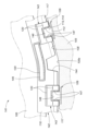
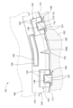
- FIG. 1 is a perspective view of a vehicle seat according to a first embodiment.
- FIG. 3 is a front view of the seat back with the outer skin removed. It is a partially enlarged view of the seat back. 3 is a sectional view taken along line IV-IV in FIG. 2.
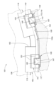
- FIG. It is a front view of the seat back of a modification. It is a perspective view of the seat of a second embodiment.
- FIG. 3 is a cross-sectional view (a cross section perpendicular to the extending direction of the hanging groove) of the hanging portion of the first embodiment.
- FIG. 2 is a perspective view of a hanging member and a displacement suppressing member of the first embodiment.
- FIG. 7 is a perspective view of a hanging member and a displacement suppressing member according to a second embodiment.
- FIG. 1 is a perspective view of a vehicle seat according to a first embodiment.
- FIG. 3 is a front view of the seat back with the outer skin removed. It is a partially enlarged view of the seat back
- FIG. 7 is a perspective view of a hanging member and a displacement suppressing member according to a third embodiment.
- FIG. 7 is a perspective view of a hanging member and a displacement suppressing member according to a fourth embodiment.
- FIG. 7 is a developed view of a displacement suppressing member according to a fourth embodiment.
- 12 is a sectional view taken along the line XIII-XIII in FIG. 11.
- FIG. It is a partially sectional side view of the hanging part of 4th Example. It is a partial cross-sectional (cross section perpendicular to the width direction of a hanging groove) side view of the hanging part of 5th Example. It is a partial cross-sectional (cross section perpendicular to the width direction of a hanging groove) side view of the hanging part of 6th Example.
- the "front-back direction” refers to the front-back direction of the vehicle seat, and is a direction that coincides with the direction in which the vehicle travels.
- the "seat width direction” is the width direction of the vehicle seat, and is a direction that coincides with the left-right direction as seen from the occupant seated on the vehicle seat.
- the "vertical direction” refers to the vertical direction of the vehicle seat, and is a direction that coincides with the vertical direction when the vehicle is traveling on a horizontal plane.
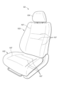
- the vehicle seat S1 of this embodiment is a seat that is placed on the floor of a vehicle body and is used by a vehicle occupant.
- the vehicle seat S1 is used as a front seat corresponding to a front seat of a vehicle.
- the vehicle seat S1 is not limited to this, and may be the rear seat of the vehicle, or may be the middle seat in the second row or the middle seat in the third row in a vehicle equipped with three rows of seats in the front and rear direction. It can also be used as a rear seat.
- the vehicle seat S1 mainly includes a seat body having a seat cushion 1, a seat back 2, and a headrest 3, and an airbag device 4.
- a seat frame F is provided inside the vehicle seat S1.
- the seat cushion 1 and the seat back 2 include a pad 10 disposed on a seat frame F and an outer skin 20 covering the pad 10. Further, the seat back 2 has a webbing 30 (guiding member) on the inner surface side of the outer skin 20 (on the pad 10 side) at a portion corresponding to the airbag device 4 .
- the pad 10 has a clip 40 (engaging member) for suspending the skin 20.
- the skin 20 has an attachment member 50 that is engaged with the clip 40.
- the skin 20 is fixed to the pad 10 by the attachment member 50 being engaged with the clip 40 and suspended.
- the clip 40 is illustrated as an engaging member, the present invention is not limited to this, and the outer skin 20 may be engaged with the pad 10 using a wire member.
- the seat cushion 1 is a seating portion that supports an occupant from below, and a pad 10 is placed on a cushion frame (not shown) that forms the skeleton of the seat cushion 1 and covered with an outer skin 20.
- the seat back 2 is a backrest portion that supports the back of the occupant from behind, and a pad 10 is placed on a seat frame F (back frame) shown in FIG.
- the seat back 2 has a back central portion 2a that supports the occupant from the rear, and a bank portion 2b that supports the occupant from the sides.
- the headrest 3 is a head that supports the occupant's head from behind, and is constructed by placing a pad material on a pillar (not shown) serving as a core material and covering it with a skin material.
- the airbag device 4 includes an airbag 4a, an inflator 4b that supplies gas to the airbag 4a, a gas blowing section 4c that blows gas into the airbag 4a, and an airbag 4a, an inflator 4b, and a gas blowing section 4c. It has a case 4d for covering and a fixture 4e for fixing the case 4d to the seat frame F.
- the airbag device 4 is attached to the right side of the seat frame F (outside the vehicle seat S1) with a fixing member 4e such as a bolt, and is housed inside the pad 10.
- a fixing member 4e such as a bolt
- the pad 10 has a cushion portion formed of a foam, and the cushion portion is covered with an outer skin 20.
- This foam may be polypropylene bead foam, polyethylene bead foam, polypropylene foam, polyethylene foam, acrylonitrile/styrene foam, ethylene vinyl acetate copolymer resin, urethane foam material, or a combination thereof. Ru.
- the pad 10 is a urethane pad formed by foam molding using a urethane foaming agent.
- the pad 10 of the seat back 2 is formed with two suspension grooves 10a extending in the longitudinal direction of the seat and a horizontal suspension groove 10b extending in the width direction of the seat.
- the horizontal suspension groove 10b connects the upper ends of the two suspension grooves 10a.
- the arrangement of the suspension groove 10a and the horizontal suspension groove 10b is an example, and the horizontal suspension groove 10b is arranged between the two suspension grooves 10a, so that the suspension groove 10b has a substantially H-shape when viewed from the front of the seat. may be formed.
- a plurality of clips 40 are provided inside the hanging groove 10a at predetermined intervals.
- the clip 40 is fixed to the pad 10 by being partially buried in the bottom of the hanging groove 10a, as shown in FIG.
- the pad 10 of the seat back 2 is formed with an accommodating portion 10c that accommodates the airbag device 4 and a slit 10d that makes it easy to break the pad 10.
- the housing portion 10c is a space that houses the airbag device 4 attached to the seat frame F.
- the slit 10d is a portion torn by the airbag 4a bulging from the case 4d.
- the skin 20 is made of cloth, film, cloth, leather, sheet, etc., and is attached to cover the pad 10 under a predetermined tension.
- the skin 20 covering the seat back 2 includes a central portion 21 that covers the front side of the back central portion 2a, and a first side portion that covers the inner side in the seat width direction (occupant side) of the bank portion 2b. 22, and a second side portion 23 that covers the outer side of the bank portion 2b in the sheet width direction.
- the first side portion 22 is joined to the outer end portion 21a of the center portion 21 in the sheet width direction.
- the second side portion 23 is joined to the first side outer end portion 22b of the first side portion 22 on the outer side in the sheet width direction.
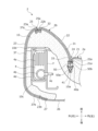
- the first joint portion 24 where the center portion 21 and the first side portion 22 are joined is the end portion 21a of the center portion 21 and the inner end of the first side portion. 22a are connected by sewing.
- the second joint portion 25 (joint portion) where the first side portion 22 and the second side portion 23 are joined is formed by connecting the first side outer end portion 22b and the front end portion 23a of the second side portion 23 by sewing. Ru.
- the second joint portion 25 is formed with a break portion 25a (tear line) that breaks when the airbag 4a is deployed. Note that the rear end portion 23b of the second side portion 23 is connected to the skin back portion 26 that covers the back side of the pad 10 via a wire fastener 27.
- the webbing 30 is a guide member that guides the deployment of the airbag 4a. As shown in FIGS. 1 to 4, the webbing 30 is disposed on the inner surface side of the skin 20 (on the pad 10 side) at a location corresponding to the airbag device 4.
- the webbing 30 includes an inner webbing (chest webbing 31 and waist webbing 34) provided along the first side portion 22 and an outer wefting cloth 37 provided along the second side portion 23.
- the inner webbing is divided into upper and lower parts, with a chest webbing 31 (first guide member) located at the height of the occupant's chest, and a chest webbing 31 (first guide member) located below the chest hem 31 and placed at the height of the occupant's waist.
- a waist cloth 34 (second guide member) disposed at the waist.
- the webbing 30 is also called an inner webbing, and is made of a material with a smaller amount of tensile elongation than the outer skin 20.
- the webbing 30 is formed of a sheet-like member having less elasticity than the skin 20. Therefore, the force cloth 30 can transmit the force applied when the airbag 4a is deployed to the tear line 25a, thereby promoting the deployment of the airbag 4a.
- one end of the webbing 30 in the sheet width direction is joined to the first side portion 22 at the broken part 25a of the second joint 25, and the other end of the webbing 30 in the sheet width direction
- the end portion is joined to the first side portion 22 at a first joint portion 24 .
- the webbing 30 is suspended and fixed to the pad 10 together with the outer skin 20 by the attachment member 50 being engaged with the clip 40 .
- the chest welt 31 has an outer end in the sheet width direction (chest welt outer end 32) and a first side outer end 22b of the first side 22 sewn together at the second joint 25. , the inner end in the sheet width direction (the inner end 33 of the chest cloth) and the first side inner end 22a of the first side 22 are sewn together at the first joint 24, so that the outer skin It is fixed at 20. Since the attachment member 50 is co-stitched together with the outer skin 20, the chest cloth 31 is fixed to the pad 10 by the attachment member 50 being engaged with the clip 40 and suspended.
- the waist welt 34 has one end (outer end 35 of the waist welt) in the seat width direction and the first side outer end 22b of the first side 22 sewn together at the second joining part 25;
- the end portion (the inner end portion 36 of the waist cloth) and the first side inner end portion 22a of the first side portion 22 are fixed to the outer skin 20 by being sewn together at the first joint portion 24.
- the waist cloth 34 is fixed to the pad 10 by the attachment member 50 being co-stitched together with the outer skin 20, so that the attachment member 50 is engaged with the clip 40 and suspended.
- the front end (outer welt front end 37a) in the seat front-rear direction and the front end 23a of the second side part 23 are sewn together at the second joint 25, and the rear end (outer welt The rear end portion 37b) and the rear end portion 23b of the second side portion 23 are sewn together to be fixed to the outer skin 20.
- the inflation energy of the airbag 4a is transmitted to the webbing 30 via the pad 10.
- the inflation energy of the airbag 4a concentrates on the suture of the second joint 25 (broken section 25a), The suture is cut. Then, the chest cloth 31, the waist cloth 34, and the outer cloth 37 are separated at the second joint 25, the pad 10 is torn at the slit 10d, and the airbag 4a is deployed outward.
- the gas blowing part 4c of the inflator 4b of the airbag device 4 is arranged closer to the chest cloth 31 than to the waist cloth 34. That is, the chest cloth 31 is more likely to receive the load from the airbag 4a than the waist cloth 34. Therefore, the broken part 25a near the chest welt 31 is easier to cut than the broken part 25a near the waist welt 34.
- the clip 40 is an engagement member having a substantially V-shaped cross section.
- the clip 40 has a holding portion 40a that holds the attachment member 50.
- the clip 40 may have a U-shaped or C-shaped cross section.
- the clip 40 is made of resin, such as polyacetal (POM) resin, polypropylene (PP) resin, polyamide (PA) resin, polycarbonate (PC) resin, or the like.
- the clip 40 is preferably formed of polyacetal (POM) resin, which has relatively high strength.
- a plurality of clips 40 are provided inside the hanging groove 10a of the pad 10 at predetermined intervals.
- the clip 40 is integrally formed during foam molding of the pad 10, and is attached to the pad 10 while being embedded inside the pad 10.
- the outer skin 20 and the webbing 30 are fixed to the pad 10 by the attachment member 50 being engaged with the clip 40 and being suspended at the first joint portion 24 provided at a position corresponding to the suspension groove 10a.
- the clip 40 may be provided in the horizontal hanging groove 10b.
- the clip 40 is attached to the right bank portion 2b of the seat back 2 in the seat width direction, that is, the portion corresponding to the airbag device 4, where the clip 40 suspends the chest cloth 31 from the pad 10.
- one engaging member first clip 41, second clip 42
- a second engaging member third clip 43, A fourth clip 44 and a fifth clip 45.
- the chest cloth 31 is engaged with the first clip 41 and the second clip 42 and suspended from the pad 10.
- the waist cloth 34 is suspended from the pad 10 by being engaged with a third clip 43 , a fourth clip 44 , and a fifth clip 45 that are arranged below the first clip 41 and the second clip 42 .
- the first clip 41 hangs the upper part of the inner end portion 33 of the chest garment and fixes the chest garment 31 to the pad 10.
- the second clip 42 is provided below the first clip 41 and suspends the lower part of the inner end 33 of the chest cloth 31 to fix the chest cloth 31 to the pad 10.
- the third clip 43 (upper engagement member) suspends the upper part of the inner end portion 36 of the waist welt and fixes the waist welt 34 to the pad 10.
- the fourth clip 44 (intermediate engagement member) is provided below the third clip 43 and suspends the vertical center portion of the inner end 36 of the waist cloth to fix the waist cloth to the pad 10.
- the fifth clip 45 (lower engaging member) is provided below the fourth clip 44 and suspends the lower part of the inner end 36 of the waist cloth to fix the waist cloth to the pad 10.
- the mounting member 50 is a hanging tool whose tip has an arrowhead-shaped cross section.
- the mounting member 50 is made of resin, for example, polypropylene (PP) resin.
- the attachment member 50 has a distal end portion 50a that is inserted into the holding portion 40a, and a proximal end portion 50b that connects to the epidermis 20.
- the base end portion 50b is co-stitched with the outer skin 20 and the chest cloth 31 at the first joint portion 24.
- the attachment member 50 is indirectly connected to the skin 20 via a non-woven fabric (not shown).
- One end of the nonwoven fabric is fixed to the skin 20 at the first joint 24 by sewing, and the other end of the nonwoven fabric is connected to the base end 50b of the attachment member 50 by sewing.
- the outer skin 20 and the webbing 30 are fixed to the pad 10 by the distal end 50a of the attachment member 50 being engaged with the holding part 40a of the clip 40 at the first joining part 24 and being suspended. .
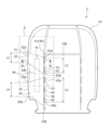
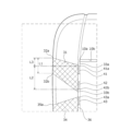
- the length L1 in the vertical direction from the first upper end 32a to the first lower end 32b at the outer end 32 of the chest dressing 31 is equal to It is shorter than the length L2 in the vertical direction from the first clip upper end 41a to the second clip lower end 42b of the second clip 42. Therefore, when a force is applied to the breaking part 25a to cut the breaking part 25a when the airbag 4a is deployed, the length L2 from the first clip upper end 41a to the second clip lower end 42b is longer than the first upper end 32a. Since it is longer than the length L1 from the first clip to the first lower end 32b, the chest cloth 31 can be stably held by the first clip 41 and the second clip 42.
- the first upper end 32a of the chest cloth 31 is arranged above the first clip upper end 41a of the first clip 41.
- the length L3 in the vertical direction between the first upper end portion 32a and the first clip upper end portion 41a is the vertical length from the first clip upper end portion 41a of the first clip 41 to the second clip lower end portion 42b of the second clip 42. It is shorter than the length L2 in the direction. Therefore, the uneven load from the chest cloth 31 can be stably supported by the first clip 41 and the second clip 42.
- the second upper end 33a of the inner end 33 of the chest cloth 31 is disposed above the first clip upper end 41a, and the second lower end 33b is located above the first clip upper end 41a. 2 clip lower end portion 42b. Therefore, even if the position of the clip 40 is shifted due to the foam molding of the pad 10 when the clip 40 is embedded in the pad 10, the chest cloth 31 can be stably held by the first clip 41 and the second clip 42. I can do it.
- the length L4 in the vertical direction from the third upper end 35a to the third lower end 35b at the outer end 35 of the waist power cloth 34 is equal to the length L4 in the vertical direction from the third clip upper end 43a of the third clip 43 to the fifth clip 45. is shorter than the length L5 in the vertical direction to the fifth clip lower end 45b. Therefore, when a force is applied to the breaking part 25a to cut the breaking part 25a when the airbag 4a is deployed, the length L5 from the third clip upper end 43a to the fifth clip lower end 45b is longer than the third upper end 35a. Since the length L4 is longer than the length L4 from the third lower end portion 35b to the third lower end portion 35b, the waist cloth 34 can be stably held by the third clip 43 and the fifth clip 45.
- the length L4 in the vertical direction from the third upper end 35a to the third lower end 35b at the outer end 35 of the waist welt 34 is equal to the first upper end at the outer end 32 of the chest welt 31. It is longer than the length L1 in the vertical direction from the portion 32a to the first lower end portion 32b. Since the chest cloth 31 is arranged in the vicinity of the gas blowing part 4c of the inflator 4b, the chest cloth 31 can easily cut the broken part 25a.
- the waist dressing 34 located at a position apart from the gas blowing part 4c of the inflator 4b is configured such that the length L4 of the outer end 35 of the waist dressing is longer than the length L1 of the outer end 32 of the chest dressing. , the broken portion 25a can be easily cut out.
- the webbing 30 receives the inflation energy of the airbag 4a
- the inflation energy can be received by the clip 40 via the nonwoven fabric at the first joint 24.
- the interval between the clips 40 is preferably 40 mm to 65 mm.
- first clip 41 and the second clip 42 are within the vertical length range of the chest cloth 31, and the third clip 43, the fourth clip 44, and the fifth clip 45 are within the length range of the waist cloth 31.
- the length is within the upper and lower length range.
- the first upper end 32a of the outer end 32 of the chest dressing is arranged above the second upper end 33a of the inner end 33 of the chest dressing. Since the first lower end portion 32b is disposed above the second lower end portion 33b of the inner end portion 33 of the chest cloth, the entire first cloth is disposed diagonally. Note that, on the side of the outer webbing rear end portion 37b, the expansion energy of the airbag 4a can be received by the second side portion 23.
- the gas blowing portion 4c of the inflator 4b of the airbag device 4 is arranged closer to the waist cloth 34 than to the chest cloth 31. That is, the waist cloth 34 is more likely to receive the load from the airbag 4a than the chest cloth 31. Therefore, the broken part 25a near the waist welt 34 is easier to cut than the broken part 25a near the chest welt 31.
- the waist cloth 34 is arranged in the vicinity of the gas blowing part 4c of the inflator 4b, the chest cloth 31 becomes easier to cut through the broken part 25a.
- the waist dressing 34 located close to the gas blowing part 4c of the inflator 4b is configured such that the length L4 of the outer end 35 of the waist dressing is longer than the length L1 of the outer end 32 of the chest dressing. , the fracture portion 25a can be cut more easily.
- a method for manufacturing the vehicle seat S1 will be described. First, the seat frame F (back frame) of the seat back 2 is prepared. An airbag device 4 having an airbag 4a and an inflator 4b is attached to the right side of the seat frame F with a fixing member 4e such as a bolt. Then, the pad 10 is placed on the seat frame F to which the airbag device 4 is attached. At this time, the airbag device 4 is accommodated in the accommodation portion 10c of the pad 10.
- a skin 20 is provided with a webbing 30 provided on the inner surface for guiding the deployment of an airbag 4a.
- the webbing 30 is placed at a position corresponding to the airbag device 4, and the outer skin 20 and the webbing 30 are sewn together to attach the webbing 30 to the inner surface of the outer skin 20.
- the pad 10 is covered with the skin 20 to which the cloth 30 is attached, and the skin 20 is hung onto the pad 10 via the clip 40.
- the first clip is longer than the length in the vertical direction from the first upper end 32a to the first lower end 32b at the outer end 32 of the chest garment 30.
- the first joint portion 24 of the skin 20 is engaged with and suspended from the clip 40, which has a long length in the vertical direction from the upper end portion 41a to the second clip lower end portion 42b.
- the skin 20 includes a central portion 21 that covers the back central portion 2a, which is the central portion of the pad 10 in the seat width direction, and a first side portion 22 that is joined to an end portion 21a of the central portion 21 in the sheet width direction. a second side portion 23 joined to the first side outer end 22b in the sheet width direction of the first side portion 22; a first joint portion 24 where the center portion 21 and the first side portion 22 are joined; It has a second joint part 25 where the first side part 22 and the second side part 23 are joined.
- the first joint part 24 is engaged with the clip 40 and suspended from the pad 10, and the second joint part 25 is formed with a breaking part 25a that breaks when the airbag 4a is deployed.
- the outer end 32 of the chest welt 30 is joined to the first side 22 at the broken part 25a, and the inner end 33 of the chest welt 30 is joined to the first side 22 at the first joint 24. It is joined with.
- the gas blowing part 4c of the inflator 4b is preferably arranged closer to the chest cloth 31 than to the waist cloth 34. Further, the gas blowing portion 4c of the inflator 4b may be arranged closer to the waist cloth 34 than to the chest cloth 31.
- first upper end portion 32a is arranged above the first clip upper end portion 41a, and the length of the first upper end portion 32a and the first clip upper end portion 41a in the vertical direction is from the first clip upper end portion 41a. It is preferable that the length is shorter than the length in the vertical direction up to the second clip lower end portion 42b. Further, the second upper end portion 33a is preferably disposed above the first clip upper end portion 41a, and the second lower end portion 33b is preferably disposed below the second clip lower end portion 42b. Further, the length in the vertical direction from the third clip upper end 43a to the fifth clip lower end 45b is preferably longer than the length in the vertical direction from the third upper end 35a to the third lower end 35b. Further, the length in the vertical direction from the third upper end portion 35a to the third lower end portion 35b is preferably longer than the length in the vertical direction from the first upper end portion 32a to the first lower end portion 32b.
- a method for manufacturing a vehicle seat comprising: Prepare the frame, Attaching an airbag device having an airbag and an inflator to the frame, placing a pad on the frame; preparing a skin whose inner surface is provided with a guide member for guiding the deployment of the airbag; arranging the guide member at a position corresponding to the airbag device and covering the pad with the skin; suspending the epidermis onto the pad via an engagement member,
- the skin includes a center portion that covers a center portion of the pad in the seat width direction, a first side portion joined to an end portion of the center portion in the seat width direction, and an outer side of the first side portion in the seat width direction.
- a second side portion joined to the end portion; a first joint portion joined to the center portion and the first side portion; and a second joint portion joined to the first side portion and the second side portion.
- a joint The first joint portion is engaged with the engagement member and suspended from the pad, A breaking part that breaks when the airbag is deployed is formed in the second joint part, A first end portion, which is an outer end portion of the guide member in the sheet width direction, is joined to the first side portion at the broken portion, A second end portion, which is an inner end portion of the guide member in the sheet width direction, is joined to the first side portion at the first joint portion, Suspending the skin onto the pad via the engaging member means that the length from the first upper end to the first lower end of the guide member is longer than the length in the vertical direction from the first upper end to the first lower end at the first end of the guide member.
- a method of manufacturing a vehicle seat comprising: engaging and suspending the first bonded portion of the skin with the engaging member having a long length in the vertical direction up to a lower end.
- a vehicle seat used in a car was explained as a specific example, but the invention is not limited to a two-wheeled seat for a motorcycle, a seat for a vehicle such as a train or a bus, a seat for a vehicle such as an airplane or a ship, etc. In addition, it can be used for various seats such as office chairs for work, wheelchairs, children's chairs for shopping carts, etc.
- the vehicle seat according to the present invention has been mainly described.
- the embodiments described above are merely examples for facilitating understanding of the present invention, and do not limit the present invention.
- the present invention may be modified and improved without departing from its spirit, and it goes without saying that the present invention includes equivalents thereof.
- the second embodiment relates to a vehicle seat in which a skin material is secured to a clip in a hanging portion, and a method for hanging the skin material.
- a linearly recessed hanging portion may be provided on the seating surface of the seat cushion and seat back in order to maintain the external shape (for example, Japanese Patent Application Publication No. 2011-069417, Japanese Patent Application Publication No. 2013 -132328).
- a suspension groove is formed in the seating surface of the pad, and a clip fixed to the pad at the bottom of the suspension groove is attached to a skin material to extend the suspension groove.
- a structure is described in which a hanging portion is formed by fixing a hanging member extending in the direction in which the hanging member extends.
- the hanging member includes a skin connecting part (hanging cotton cloth) attached to the skin material, and a bulging part (suspenders) connected to the lower edge of the skin connecting part and bulging in the width direction of the hanging groove. , the bulge is locked to the clip.
- a hanging member including a skin connecting part (attachment part) and a bulging part that is latched to a clip is disclosed.
- the hanging member is prevented from coming off by inserting the tip of the clip into the hole provided in the skin connecting portion.
- the tip of the clip is inserted into the hole at a position shifted from the original position in the extending direction of the hanging groove, or the tip of the clip is assembled without being inserted into the hole, Thereafter, the external shape of the vehicle seat may be distorted due to the displacement away from the hole from the original position.
- an object of the present invention is to provide a vehicle seat including a hanging portion that can suppress displacement of the hanging member in the extending direction of the hanging groove and whose position can be easily adjusted.
- a vehicle seat includes a pad that is a cushion body having a hanging groove recessed in the seating surface, and a pad that is stretched over the seating surface of the pad. a skin material, a substrate embedded in a portion of the pad located at the bottom of the hanging groove, and a locking piece that is erected from the substrate and has a locking claw located in the hanging groove.
- a clip including a strip, a skin connecting part extending in the extending direction of the hanging groove and connected to the skin material at one side edge; a hanging member including a bulging portion provided to bulge in the width direction of the hanging groove and locked to the locking claw of the clip; and a hanging member fixed to the skin connecting portion by sewing, and the locking member and a positional displacement suppressing member having an end face facing the extending direction so as to be able to come into contact with the piece.
- the end face of the displacement suppressing member comes into contact with the locking piece, thereby suppressing displacement of the hanging member in the extending direction. Further, since the positional displacement suppressing member is fixed to the skin connecting portion by sewing, the position relative to the clip can be easily adjusted.
- the displacement suppressing member may be formed by folding the longitudinal end of the hanging member onto the main body of the hanging member.
- one component since one component includes a portion that constitutes the main body of the suspension member and a portion that constitutes the positional displacement suppressing member, an increase in the number of components can be suppressed.
- the bulging portion is separated between the main body and the positional displacement suppressing member.
- the bulging portion is divided, it becomes easy to fold the displacement suppressing member onto the main body of the hanging member.
- the displacement suppressing member may be separate from the hanging member.
- the displacement suppressing member can be provided not only for the clips disposed near the ends in the extending direction of the hanging groove but also for the clips disposed at the intermediate portion.
- the displacement suppressing member may be made of the same material as the hanging member.
- the material of the misalignment suppressing member is the same as the material of the hanging member, the effort required to create the misalignment suppressing member is reduced.
- the displacement suppressing member may be configured to overlap the hanging member from both sides in the width direction so as to surround the bulged portion, and to have an opening defining the end surface.
- An aspect of the present invention is a method for suspending the skin material in the vehicle seat according to the above aspect, comprising: fixing the displacement suppressing member to the skin connecting portion by sewing; and a step of locking the bulge.
- displacement of the hanging member in the extending direction can be suppressed by the positional displacement suppressing member, and since the positional displacement suppressing member is fixed to the skin connecting portion by sewing, the position relative to the clip can be easily adjusted. Can be adjusted.
- the method further includes the step of providing the displacement suppressing member by folding the longitudinal end of the hanging member onto the main body of the hanging member, and the fixing step includes the step of folding the longitudinal end of the hanging member onto the main body of the hanging member, and the fixing step includes The method includes fixing the skin connecting portion of the displacement suppressing member to the connecting portion by sewing.
- one component since one component includes a portion that constitutes the main body of the suspension member and a portion that constitutes the positional displacement suppressing member, an increase in the number of components can be suppressed.
- the step of providing the suspension member may include dividing the bulge portion between the main body and the displacement suppressing member.
- the bulging portion is divided, it becomes easy to fold the displacement suppressing member onto the main body of the hanging member.
- the step of providing the displacement suppressing member includes dividing the bulge between the main body and the displacement suppressing member.
- the bulging portion is divided, it becomes easy to fold the displacement suppressing member onto the main body of the hanging member.
- the displacement suppressing member may be separate from the hanging member.
- the displacement suppressing member can be provided not only for the clips disposed near the ends in the extending direction of the hanging groove but also for the clips disposed at the intermediate portion.
- the method further comprises a step of creating a material including the skin connecting part and the bulging part, and a step of cutting the material to create the hanging member and the displacement suppressing member,
- the step of fixing may include fixing the skin connecting portion of the displacement suppressing member to the skin connecting portion of the hanging member by sewing.
- the material of the misalignment suppressing member is the same as the material of the hanging member, it takes less effort to create the misalignment suppressing member.
- the positional displacement suppressing member has an opening defining the end surface and is flexible
- the fixing step includes fixing the positional displacement suppressing member to the locking member in the bulged portion.
- the method further includes stacking the hanging member from both sides in the width direction and fixing it to the skin connecting portion by sewing so that the portion to be locked by the nail is exposed by the opening and surrounds the bulging portion. But it's okay.
- one component includes a portion constituting the main body of the hanging member and a portion forming the main body of the hanging member. Since it includes a portion constituting a positional displacement suppressing member, an increase in the number of parts can be suppressed.
- the positional displacement suppressing member is separate from the hanging member, it is possible to configure a hanging portion that can suppress positional displacement of the hanging member and whose position is easily adjusted with a simple configuration,
- the displacement suppressing member can be provided not only for the clips disposed near the ends in the extending direction of the hanging groove but also for the clips disposed at the intermediate portion.
- the displacement suppressing member is made of the same material as the hanging member, the effort required to create the displacement suppressing member is reduced.
- the positional displacement suppressing member is separate from the hanging member, if the positional displacement suppressing member has an opening that defines an end surface, it can be positioned in both directions in the extending direction with a simple configuration. Misalignment can be suppressed.
- FIG. 6 is a perspective view of a vehicle seat S2 (hereinafter referred to as "seat S2") according to the second embodiment.
- the seat S2 includes a seat cushion 102 supported by the vehicle body, a seat back 103 connected to the seat cushion 102, and a headrest 104 connected to the seat back 103.
- Each of the seat cushion 102, the seat back 103, and the headrest 104 includes a pad 105 (see FIG. 2) made of foamed resin such as foamed urethane, and a skin material 106 that covers the seating surface of the pad 105.
- a plurality of hanging portions 107 are formed in the vertical and horizontal directions by recessing the skin material 106 into the pad 105. .
- FIG. 2 shows the hanging part 107 according to the first example of the second embodiment in a cross section perpendicular to the extending direction of the hanging part 107.
- the hanging portion 107 of the seat S2 includes a pad 105 having a hanging groove 108 recessed in the seating surface, and a skin material 106 stretched over the seating surface of the pad 105. , a clip 109 fixed to the pad 105 so as to be disposed in the hanging groove 108 , a hanging member 110 connected to the skin material 106 and locked to the clip 109 , and a hanging member 110 coupled to the hanging member 110 . and a positional displacement suppressing member 111.
- the pad 105 is a cushion body made of foamed resin such as foamed urethane.
- the hanging groove 108 is open toward the seating surface, and extends in the vertical direction (the front-rear direction in the seat cushion 102 and the up-down direction in the seat back 103), and in the horizontal direction (the left-right direction). including existing ones.
- the depth of the hanging groove 108 is substantially constant, and the bottom surface of the hanging groove 108 extends on a substantially flat surface.
- the terms "extending direction” and “width direction” refer to the extending direction and width direction of the hanging groove 108.
- the skin material 106 is a member made of leather, cloth, or the like that constitutes the surface of the seating surface of the seat S2 (see FIG. 6).
- the clip 109 includes a substrate 112 embedded in a portion of the pad 105 located at the bottom of the hanging groove 108 and a pair of locking pieces 113 erected from the substrate 112, and is made of, for example, resin. It is an injection molded product.
- the substrate 112 has a generally flat plate shape and is arranged approximately parallel to the bottom surface of the hanging groove 108 . The entire substrate 112 is buried in the pad 105, but it is buried in the pad 105 at both ends in the width direction, and the surface on which the locking piece 113 is provided is exposed from the pad 105 at the center in the width direction.
- the pair of locking pieces 113 are opposed to each other in the width direction, and stand upright toward the opening of the suspension groove 108 from a portion of the substrate 112 that is further inward in the width direction than the inner surface of the suspension groove 108 . and a locking pawl 115 formed to extend inward in the width direction from the tip of the upright portion 114 so as to be inclined toward the bottom surface of the hanging groove 108. .
- the tips of the pair of locking claws 115 are spaced apart from each other in the width direction.
- the locking piece 113 is elastically deformable so that the distance between the tips of the pair of locking claws 115 increases.
- the upright portion 114 is capable of elastic deformation such that its tip is curved or tilted outward in the width direction, and/or the locking pawl 115 is elastically deformable so that its tip approaches the upright portion 114. It can be elastically deformed by bending or tilting.
- the hanging member 110 is arranged within the hanging groove 108, and its longitudinal direction coincides with the extending direction of the hanging groove 108.
- the hanging member 110 includes a band-shaped skin connecting portion 116 extending along the longitudinal direction of the hanging member 110 and a side edge of the skin connecting portion 116 extending along the longitudinal direction of the hanging member 110. bulging portion 117 .
- the skin connecting portion 116 is formed of a material that can be sewn, such as a nonwoven fabric or a woven fabric.
- the skin connecting portion 116 is connected to the skin material 106 by sewing at the side edge on the opening side of the hanging groove 108, and is connected to the bulging portion 117 at the side edge on the bottom side of the hanging groove 108.
- the bulging portion 117 has a shape that bulges in the width direction with respect to the skin connecting portion 116 and is locked by the locking claw 115. Therefore, in the clip 109, the distance between the tips of the pair of locking claws 115 can be narrower than the width of the bulge 117 before elastic deformation, and can be greater than the width of the bulge 117 during elastic deformation. It is configured like this.
- the bulging portion 117 is made of resin and is formed by injection molding.
- the bulging portion 117 is connected to the skin connecting portion 116 by injection molding with the skin connecting portion 116 attached to a mold cavity.
- the hanging member 110 may be made of resin in which the skin connecting portion 116 and the bulging portion 117 are integrally molded.
- FIG. 8 is a perspective view showing the hanging member 110 and the displacement suppressing member 111.
- the displacement suppressing member 111 extends substantially on a plane by connecting the longitudinal end of the hanging member 110 to the main body 110a of the hanging member 110 (including the portion that engages with the clip 109). It is made up of the part that is folded back on top.
- the bulge 117 of the displacement suppressing member 111 is arranged adjacent to the bulge 117 of the main body 110a of the hanging member 110.
- the skin connecting portion 116 of the displacement suppressing member 111 is fixed to the skin connecting portion 116 of the main body 110a of the hanging member 110 by sewing at the side edge on the opening side of the hanging groove 108.
- the side edge of the hanging member 110 on the side where the bulging part 117 is provided has a position with the main body 110a of the hanging member 110. It is preferable that a notch 118 is provided between the displacement suppressing member 111 and the displacement suppressing member 111 .
- the notch 118 divides the bulging portion 117 into a main body 110a side and a displacement suppressing member 111 side. Instead of the notch 118, by cutting the side edge of the hanging member 110 on the side where the bulge 117 is provided and providing a slit (not shown), the bulge 117 can be connected to the main body 110a side. It may be divided into the positional deviation suppressing member 111 side.
- the locking piece 113 of the clip 109 disposed closest to the displacement suppressing member 111 extends further than the positional displacement suppressing member 111.
- An end surface 119 located at the center of the direction and facing the center of the displacement suppressing member 111 in the direction of extension can come into contact with a side surface of the locking piece 113 in the direction of extension.
- the end surface 119 may actually be in contact with the side surface of the locking piece 113, or there may be a gap between the end surface 119 and the side surface of the locking piece 113.
- the distance between the end surface 119 and the side surface of the locking piece 113 is equal to or less than a length that allows displacement of the hanging member 110 in the extending direction.
- the end surface 119 of the displacement suppressing member 111 can come into contact with the side surface of the locking piece 113 at the skin connecting portion 116, the bulging portion 117, or both.
- a worker attaches the clip 109 in a mold (not shown), injects foamed resin raw material into the mold, and foams and hardens it to form a pad 105 in which the clip 109 is embedded.
- the worker fixes the hanging member 110 to the skin material 106 by sewing (numeral 120 indicates thread for sewing).
- the displacement suppressing member 111 is fixed to the skin material 106 together with the main body 110a of the hanging member 110 by sewing. Note that, after the main body 110a of the hanging member 110 is fixed to the skin material 106 by sewing, the displacement suppressing member 111 is attached to a portion where the skin material 106 and the skin connecting portion 116 of the main body 110a of the hanging member 110 overlap. It may be fixed by sewing, and after fixing the main body 110a of the hanging member 110 to the skin material 106 by sewing, it is not fixed to the skin material 106 but is sewn to the skin connecting portion 116 of the main body 110a of the hanging member 110. Alternatively, it may be fixed first by sewing to the skin connecting portion 116 of the main body 110a of the hanging member 110, and then to the skin material 106 together with the main body 110a by sewing.
- the worker inserts the hanging member 110 from the bulging part 117 into the hanging groove 108 and presses the bulging part 117 against the pair of locking claws 115 of the clip 109, thereby locking the pair of locking members 110 into the hanging groove 108.
- the locking piece 113 of the clip 109 is elastically deformed so that the distance between the tips of the claws 115 increases, and the bulging portion 117 is passed between the tips of the pair of locking claws 115. After the bulging portion 117 passes between the tips of the pair of locking pawls 115, the locking piece 113 returns to its original shape, thereby locking the bulging portion 117 to the locking pawl 115.
- the hanging member 110 is prevented from shifting in the extending direction in the direction in which the end surface 119 faces. Ru. Therefore, deterioration of the appearance of the sheet S2 due to misalignment of the hanging member 110 can be suppressed.
- the sewing thread 120 can be untied and resewn, and the position of the misalignment suppressing member 111 relative to the clip 109 can be adjusted. is easy.
- the position of the misalignment suppressing member 111 with respect to the clip 109 Since the positional displacement suppressing member 111 can be fixed to the main body 110a of the hanging member 110 after adjusting the positional displacement suppressing member 111, the position of the positional displacement suppressing member 111 relative to the clip 109 can be easily adjusted. In addition, if the end face 119 of the displacement suppressing member 111 is located near the center in the extending direction beyond the side surface of the locking piece 113 of the clip 109, position displacement can also be suppressed by cutting the beyond part. The position of member 111 can be adjusted.
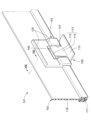
- FIG. 9 is a perspective view showing the hanging member 110 and the displacement suppressing member 111 in the hanging part 121.
- the displacement suppressing member 111 is provided only at one end in the longitudinal direction of the hanging member 110, but the hanging portion 121 and the displacement suppressing member 111 in the second embodiment are , are provided at both ends of the hanging member 110 in the longitudinal direction. Therefore, at one end in the longitudinal direction, the end surface 119 of the displacement suppressing member 111 can come into contact with the side surface of the locking piece 113 of the clip 109 in the opposite direction to the other end. Therefore, positional displacement of the hanging member 110 is suppressed in both directions in which the hanging groove 108 extends. Other effects are the same as in the first embodiment.
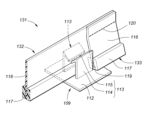
- FIG. 10 is a perspective view showing the hanging member 132 and the displacement suppressing member 133 in the hanging part 131.
- the hanging portion 131 according to the third embodiment is different from the first embodiment in that the hanging member 132 and the displacement suppressing member 133 are separate bodies.
- the displacement suppressing member 133 is made of the same material as the hanging member 132.
- the materials for creating the hanging member 132 and the positional shift suppressing member 133 are created by the same method as the method for creating the hanging member 110 (see FIG. 8) described in the first embodiment. Therefore, this material includes a skin connection part 116 and a bulge part 117.
- the length of this material is set to be longer than the total length of the hanging member 132 and the displacement suppressing member 133 in the longitudinal direction.
- the hanging member 132 and the displacement suppressing member 133 are created by cutting this material in a plane perpendicular to the extending direction.
- the third embodiment has the same effects as the first embodiment except for the notch 118 (see FIG. 8).
- the displacement suppressing member 133 may be attached not only to one end of the hanging member 132 in the longitudinal direction but also to both ends thereof.
- the displacement suppressing member 133 may be provided not only at a position where it abuts the clip 109 provided at the end portion in the extending direction, but also at a position where it abuts the clip 109 provided at the intermediate portion in the extending direction. .
- the displacement suppressing member 133 is provided only on one side of one clip 109 in the extending direction, but may be provided on both sides.
- One displacement suppressing member 133 disposed between two clips 109 may be able to abut on the corresponding clips 109 at both end faces 119 in the extending direction.
- FIG. 11 is a perspective view showing the hanging member 142 and the displacement suppressing member 143 in the hanging part 141
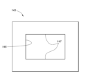
- FIG. 7 is a developed view showing the displacement suppressing member 143
- FIG. 13 is a perspective view of the hanging member 141.
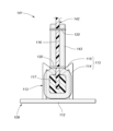
- 14 is a cross-sectional view showing how the hanging member 142 is attached to the clip 109
- FIG. 14 is a partially sectional side view showing how the hanging member 142 is attached to the clip 109.
- the fourth embodiment differs from the third embodiment in a hanging member 142 and a displacement suppressing member 143.
- the hanging member 142 is similar to the hanging member 132 of the third embodiment (see FIG. 10) in that it has a skin connecting part 116 and a bulging part 117, but The difference is that a notch 144 is provided at a bent portion 108a where the bottom surface of the groove 108 is bent.
- the cutout portion 144 is provided from the bulge portion 117, divides the bulge portion 117, and cuts out the skin connecting portion 116 in a concave shape.
- the hanging member 142 includes a plate 145 provided closer to the seating surface than the notch 144 .
- the plate 145 is fixed to one side of the skin connecting portion 116 by sewing.
- Both ends of the plate 145 in the extending direction are located further outward in the extending direction than both ends of the notch 144 in the extending direction.
- the end of the plate 145 is the end of the displacement suppressing member 143 in the extending direction when viewed from the depth direction of the hanging groove 108. It is preferable that they overlap. It is preferable that the bending rigidity of the plate 145 is higher than that of the skin connecting portion 116.
- the plate 145 is made of resin that can be sewn.
- the displacement suppressing member 143 is a flexible sheet-like member, and has an opening 146 penetrating in the thickness direction.
- the opening 146 preferably has a rectangular shape
- the outer shape of the displacement suppressing member 143 preferably also has a rectangular shape having sides parallel to the sides of the opening 146.
- the displacement suppressing member 143 has a predetermined thickness, and an end surface 147 is formed on the inner circumference of the displacement suppressing member 143 that defines the opening 146.
- the displacement suppressing member 143 preferably has a thickness greater than that of the skin connecting portion 116, and is made of felt, for example.
- the displacement suppressing member 143 has a portion of the bulging portion 117 of the hanging member 132 that is locked by the locking claw 115 exposed by the opening 146, and is adjacent to a portion of the bulging portion 117 exposed by the opening 146. It overlaps the bulging part 117 and the skin connection part 116 of the hanging member 132 from both sides in the width direction (the front and back directions of the skin connection part 116) so as to surround the part, and is fixed to the skin connection part 116 by sewing. Therefore, the end surfaces 147 of the displacement suppressing member 143 that are opposed to each other in the extending direction are opposed to the side surfaces of the locking piece 113 of the clip 109 in the extending direction, and a slight displacement of the hanging member 132 in the extending direction is prevented. As a result, the end surface 147 comes into contact with the locking piece 113. Note that one or both of the end surfaces 147 may be in contact with the locking piece 113 in the original position.
- the work of creating the notch 144, the work of attaching the plate 145 to the hanging member 142, and the work of attaching the misalignment suppressing member 143 to the hanging member 142 are performed in order to facilitate positional adjustment. This is performed after the restraining member 143 is attached to the skin material 106. Note that these operations may be performed before attaching the displacement suppressing member 143 to the skin material 106 in order to improve workability.
- the plate 145 moves in a direction in which the two bulges 117 facing each other with the notch 144 in between approach each other. This prevents deviation from occurring.
- the positional displacement suppressing member 143 can be applied to both the clip 109 provided at the end portion in the extending direction and the clip 109 provided at the intermediate portion.
- FIG. 15 is a partially sectional side view of the hanging portion 151.
- the fifth embodiment is different from the fourth embodiment in that the hanging member 142 in the fourth embodiment has a notch 144 (see FIG. 14), whereas the fifth embodiment has a slit 153 instead of the notch 144. do.
- the slit 153 is provided by cutting the hanging member 152 from the bulge 117 at a position corresponding to the bent portion 108a.
- the slit 153 divides the bulging portion 117 and reaches near the portion of the skin connecting portion 116 attached to the plate 145.
- the fifth embodiment has the same effects as the fourth embodiment.
- FIG. 16 is a partially sectional side view of the hanging portion 161.
- the notch 144 of the hanging member 142 in the fourth embodiment is provided from the bottom side of the hanging groove 108 (see FIG. 14)
- the notch 163 of the hanging member 162 This embodiment differs from the fourth embodiment in that a is provided from the side edge of the skin connecting portion 116 that is connected to the skin material 106, and that a plate 145 (see FIG. 14) is not provided.
- the notch 163 cuts out the skin connecting portion 116 from the side edge of the skin connecting portion 116 connected to the skin material 106 to the bulging portion 117 at a position corresponding to the bent portion 108a.
- the parts that engage with the two clips 109 are prevented from shifting in the direction toward each other.
- a pad that is a cushion body having a hanging groove recessed in the seating surface; a skin material stretched over the seating surface of the pad; a clip including a substrate embedded in a portion of the pad located at the bottom of the hanging groove, and a locking piece that is erected from the substrate and has a locking claw located in the hanging groove;
- a skin connecting part that has a band shape extending in the extending direction of the hanging groove and is connected to the skin material at one side edge, and a skin connecting part of the hanging groove on the other side edge of the skin connecting part.
- a vehicle seat comprising: a displacement suppressing member fixed to the skin connecting portion by sewing and having an end face facing the extending direction so as to be able to abut on the locking piece.
- a displacement suppressing member fixed to the skin connecting portion by sewing and having an end face facing the extending direction so as to be able to abut on the locking piece.
- the positional displacement suppressing member has an opening defining the end surface and is flexible
- the fixing step includes fixing the displacement suppressing member to the suspension member such that a portion of the bulge that is locked by the locking claw is exposed by the opening and surrounds the bulge.
- the method according to appendix 10 comprising stacking the skin from both sides in the width direction and fixing it to the skin connecting portion by sewing.
Landscapes
- Engineering & Computer Science (AREA)
- Mechanical Engineering (AREA)
- Aviation & Aerospace Engineering (AREA)
- Transportation (AREA)
- Textile Engineering (AREA)
- Manufacturing & Machinery (AREA)
- Air Bags (AREA)
Abstract
Description
例えば、特許文献1の車両用シートでは、エアバッグを遅滞なく展開させるため、力布の一端部が表皮と共に接合部分で縫製され、力布の他端部がバックフレームに固定されている。
また、例えば、特許文献2の車両用シートでは、表皮に断面が略三角形状を成したサスペンダ(取付部材)を設け、クッションパッドの吊り込み溝に埋設されたクリップ(係合部材)にサスペンダを係合して、表皮をクッションパッドに固定することが行われている。
しかしながら、サイドエアバッグが展開する際、力布の荷重が係合部材へかかるため、係合部材がクッションパッドの吊り込み溝から外れてしまうおそれがあった。
上記構成により、簡易な構造で、エアバッグ展開時の案内部材(力布)にかかる荷重を係合部材(クリップ)で安定して保持することができる。
詳しく述べると、エアバッグの展開時に、破断部(ティアライン)を切開する力が破断部にかかると、係合部材で案内部材を支持するが、案内部材の外側端部の上下長よりも、係合部材の上端から下端までの上下長のほうが長いので、案内部材を係合部材によって安定して保持することができる。
上記構成により、デザインの制約により吊り込み溝の長さを確保できず、係合部材を理想的な位置に配置できない場合でも、案内部材からの偏荷重を係合部材で安定して支持することができる。
上記構成により、簡易な構造で、エアバッグ展開時の案内部材にかかる荷重を係合部材で、より安定して保持することができる。
上記構成により、簡易な構造で、エアバッグ展開時の案内部材にかかる荷重を係合部材で、より安定して保持することができる。
上記構成により、第1案内部材は、インフレータの高圧ガス噴射口の近傍位置にあるため、破断部を切開しやすくなり、インフレータの高圧ガス噴射口と離間した位置にある第2案内部材は、破断部側の端部の上下長を長くすることで、破断部を切開しやすくできる。
上記構成により、第2案内部材は、インフレータの高圧ガス噴射口の近傍位置にあるため、より破断部を切開しやすくできる。
上記構成により、破断部側の端部の上下長が長い第2案内部材を固定する係合部材の数を多くすることで、エアバッグ展開時の案内部材にかかる荷重を係合部材で、より安定して保持することができる。
また本発明によれば、デザインの制約により吊り込み溝の長さを確保できず、係合部材を理想的な位置に配置できない場合でも、案内部材からの偏荷重を係合部材で安定して支持することができる。
また本発明によれば、簡易な構造で、エアバッグ展開時の案内部材にかかる荷重を係合部材で、より安定して保持することができる。
また本発明によれば、破断部を切開しやすくできる。
また本発明によれば、より破断部を切開しやすくできる。
また本発明によれば、エアバッグ展開時の案内部材にかかる荷重を係合部材でより安定して保持することができる。
以下、本発明に係る第一実施形態について図1~図5を参照して説明する。
以下の説明において、「前後方向」とは、車両用シートの前後方向であり、車両走行時の進行方向と一致する方向である。また、「シート幅方向」とは、車両用シートの幅方向であり、車両用シートに着座した乗員から見た左右方向と一致する方向である。また、「上下方向」とは、車両用シートの上下方向であり、車両が水平面を走行しているときには鉛直方向と一致する方向である。
本実施形態の車両用シートS1は、図1に示すように、車体フロア上に載置され、車両の乗員が着座するシートである。本実施形態において、車両用シートS1は、車両の前部座席に相当するフロントシートとして利用される。ただし、これに限定されるものではなく、車両用シートS1は、車両のリアシートであってもよく、また、前後方向に三列のシートを備える車両において二列目のミドルシートや三列目のリアシートとしても利用可能である。
車両用シートS1は、内部にシートフレームFが設けられている。シートクッション1及びシートバック2は、シートフレームFに配置されるパッド10と、パッド10を覆う表皮20と、を有する。また、シートバック2は、表皮20の内面側(パッド10側)であってエアバッグ装置4に対応する部位に、力布30(案内部材)を有する。
なお、係合部材としてクリップ40を例示したが、これ限らず、ワイヤ部材によって表皮20をパッド10に係合させても良い。
シートバック2は、乗員の背中を後方から支持する背もたれ部であって、シートバック2の骨格をなす図4に示すシートフレームF(バックフレーム)にパッド10を載置して、表皮20で被覆することで構成されている。
シートバック2は、乗員を後方から支持するバック中央部2aと、乗員を側方から支持する土手部2bと、を有する。
ヘッドレスト3は、乗員の頭を後方から支持する頭部であって、芯材となる不図示のピラーにパッド材を載置して表皮材で被覆することで構成されている。
エアバッグ装置4は、エアバッグ4aと、エアバッグ4aにガスを供給するインフレータ4bと、エアバッグ4a内にガスを噴出するガス吹出部4cと、エアバッグ4a、インフレータ4b及びガス吹出部4cを覆うケース4dと、ケース4dをシートフレームFに固定する固定具4eと、を有する。
パッド10は、発泡体によりクッション部分が形成されており、クッション部分が表皮20により被覆される。この発泡体としては、ポリプロピレンビーズ発泡体、ポリエチレンビーズ発泡体、ポリプロピレン発泡体、ポリエチレン発泡体、アクリロニトリル・スチレン発泡体、エチレン酢酸ビニル共重合樹脂、ウレタンフォーム材等、若しくはこれらを組合わせて使用される。本実施形態において、パッド10は、ウレタン発泡剤を用いて、発泡成型により成型されたウレタンパッドである。
収容部10cは、シートフレームFに取り付けられたエアバッグ装置4を収容する空間である。スリット10dは、ケース4dから膨出したエアバッグ4aにより破断する部分である。
表皮20は、布、フィルム、クロス、革やシート等により構成され、所定のテンションが掛かるように張られた状態でパッド10を覆うよう取り付けられている。
図1、図4に示すように、シートバック2を覆う表皮20は、バック中央部2aの前側を覆う中央部21と、土手部2bのシート幅方向内側(乗員側)を覆う第1側部22と、土手部2bのシート幅方向外側を覆う第2側部23と、を有する。
第1側部22は、中央部21のシート幅方向における外側の端部21aに接合される。第2側部23は、第1側部22のシート幅方向における外側の第1側部外側端部22bに接合される。
第1側部22と第2側部23とが接合される第2接合部25(接合部分)は、第1側部外側端部22bと第2側部23の前端部23aが縫製により連結される。第2接合部25は、エアバッグ4aの展開時に破断する破断部25a(ティアライン)が形成される。
なお、第2側部23の後端部23bは、パッド10の背面側を覆う表皮背面部26と、線ファスナ27を介して連結される。
力布30は、エアバッグ4aの展開を案内する案内部材である。力布30は、図1~図4に示すように、表皮20の内面側(パッド10側)であってエアバッグ装置4に対応する部位に配置されている。
力布30は、第1側部22に沿って設けられる内側力布(胸用力布31、腰用力布34)と、第2側部23に沿って設けられる外側力布37と、を有する。内側力布は、上下に分割されており、乗員の胸の高さに配置される胸用力布31(第1案内部材)と、胸用力布31よりも下方であって、乗員の腰の高さに配置される腰用力布34(第2案内部材)と、を有する。
クリップ40は、図4に示すように、断面が略V字状に形成された係合部材である。クリップ40は、取付部材50を保持する保持部40aを有する。なお、クリップ40は断面がU字状、又はC字状に形成されてもよい。
クリップ40は樹脂製であり、例えばポリアセタール(POM)樹脂、ポリプロピレン(PP)樹脂、ポリアミド(PA)樹脂、ポリカーボネート(PC)樹脂等から形成される。なお、クリップ40は、比較的強度の高いポリアセタール(POM)樹脂により形成されると良い。
表皮20及び力布30は、吊り込み溝10aと対応する位置に設けられる第1接合部24において、取付部材50がクリップ40に係合されて吊り込まれることで、パッド10に固定される。なお、クリップ40は、横吊り込み溝10bに設けられても良い。
胸用力布31は、第1クリップ41及び第2クリップ42に係合されてパッド10に吊り込まれる。腰用力布34は、第1クリップ41及び第2クリップ42よりも下方に配置される第3クリップ43、第4クリップ44、及び第5クリップ45に係合されてパッド10に吊り込まれる。
第2クリップ42は、第1クリップ41より下方に設けられ、胸用力布内側端部33の下方部分を吊り込んで、胸用力布31をパッド10に固定する。
第4クリップ44(中間係合部材)は、第3クリップ43より下方に設けられ、腰用力布内側端部36の上下方向における中央部分を吊り込んで、腰用力布34をパッド10に固定する。
第5クリップ45(下部係合部材)は、第4クリップ44より下方に設けられ、腰用力布内側端部36の下方部分を吊り込んで、腰用力布34をパッド10に固定する。
取付部材50は、図4に示すように、先端部分の断面が矢じり形状に形成された掛け具である。取付部材50は樹脂製であり、例えばポリプロピレン(PP)樹脂により形成される。
取付部材50は、保持部40aに挿入される先端部50aと、表皮20と接続する基端部50bと、を有する。基端部50bは、第1接合部24において、表皮20及び胸用力布31と共縫いされている。なお、取付部材50は、不図示の不織布を介して間接的に表皮20と接続する。不織布の一端側が縫製により表皮20と第1接合部24で固定され、不織布の他端側が、取付部材50の基端部50bと縫製により接続される。
このように、表皮20及び力布30は、第1接合部24において、取付部材50の先端部50aがクリップ40の保持部40aに係合されて吊り込まれることで、パッド10に固定される。
図2、図3に示すように、胸用力布31の胸用力布外側端部32における第1上端部32aから第1下端部32bまでの上下方向における長さL1は、第1クリップ41の第1クリップ上端部41aから第2クリップ42の第2クリップ下端部42bまでの上下方向における長さL2よりも短い。
したがって、エアバッグ4aの展開時に、破断部25aを切開する力が破断部25aにかかると、第1クリップ上端部41aから第2クリップ下端部42bまでの長さL2のほうが、第1上端部32aから第1下端部32bまでの長さL1よりも長いので、第1クリップ41及び第2クリップ42によって胸用力布31を安定して保持することができる。
したがって、胸用力布31からの偏荷重を第1クリップ41及び第2クリップ42によって安定して支持することができる。
したがって、クリップ40をパッド10に埋設したときに、パッド10の発泡成型によりクリップ40の位置がずれた場合でも、第1クリップ41及び第2クリップ42によって胸用力布31を安定して保持することができる。
したがって、エアバッグ4aの展開時に、破断部25aを切開する力が破断部25aにかかると、第3クリップ上端部43aから第5クリップ下端部45bまでの長さL5のほうが、第3上端部35aから第3下端部35bまでの長さL4よりも長いので、第3クリップ43及び第5クリップ45によって腰用力布34を安定して保持することができる。
胸用力布31がインフレータ4bのガス吹出部4cの近傍位置に配置されるため、胸用力布31は、破断部25aを切開しやすくなる。また、インフレータ4bのガス吹出部4cと離間した位置にある腰用力布34は、腰用力布外側端部35の長さL4を胸用力布外側端部32の長さL1よりも長くすることで、破断部25aを切開しやすくできる。
そして、胸用力布31において、胸用力布外側端部32における第1上端部32aは、胸用力布内側端部33の第2上端部33aよりも上方に配置され、胸用力布外側端部32における第1下端部32bは、胸用力布内側端部33の第2下端部33bよりも上方に配置されているため、第1力布全体として斜めに配置されている。
なお、外側力布後端部37b側では、エアバッグ4aの膨張エネルギを第2側部23で受け止めることができる。
次に、車両用シートS1の変形例について、図5に基づいて説明する。なお、上述の車両用シートS1と重複する内容については説明を省略する。
変形例の車両用シートS1では、エアバッグ装置4のインフレータ4bにおけるガス吹出部4cは、胸用力布31よりも腰用力布34の近傍に配置される。すなわち、胸用力布31よりも腰用力布34の方が、エアバッグ4aによる荷重を受けやすい。そのため、腰用力布34近傍の破断部25aは、胸用力布31近傍の破断部25aよりも切開しやすい。
車両用シートS1の製造方法について説明する。
まず、シートバック2のシートフレームF(バックフレーム)を用意する。シートフレームFの右側面に、エアバッグ4aとインフレータ4bを有するエアバッグ装置4をボルト等の固定具4eで取り付ける。
そして、エアバッグ装置4を取り付けたシートフレームFにパッド10を配置する。このとき、パッド10の収容部10cに、エアバッグ装置4を収容する。
そして、パッド10を力布30が取り付けられた表皮20で覆い、クリップ40を介して表皮20をパッド10に吊り込む。
第1接合部24は、クリップ40に係合されてパッド10に吊り込まれており、第2接合部25には、エアバッグ4aの展開時に破断する破断部25aが形成される。
力布30の胸用力布外側端部32は、破断部25aにおいて第1側部22と接合され、力布30の胸用力布内側端部33は、第1接合部24において第1側部22と接合される。
また、インフレータ4bにおけるガス吹出部4cは、胸用力布31よりも腰用力布34の近傍に配置されても良い。
また、第2上端部33aは、第1クリップ上端部41aよりも上方に配置され、第2下端部33bは、第2クリップ下端部42bよりも下方に配置されると良い。
また、第3クリップ上端部43aから第5クリップ下端部45bまでの上下方向における長さは、第3上端部35aから第3下端部35bまでの上下方向における長さよりも長いと良い。
また、第3上端部35aから第3下端部35bまでの上下方向における長さは、第1上端部32aから第1下端部32bまでの上下方向における長さよりも長いと良い。
車両用シートの製造方法であって、
フレームを用意し、
前記フレームに、エアバッグとインフレータを有するエアバッグ装置を取り付け、
前記フレームにパッドを配置し、
前記エアバッグの展開を案内する案内部材が内側面に設けられた表皮を用意し、
前記エアバッグ装置に対応する位置に前記案内部材を配置して、前記パッドを前記表皮で覆い、
係合部材を介して前記表皮を前記パッドに吊り込むこと、を含み、
前記表皮は、前記パッドのシート幅方向における中央部分を覆う中央部と、前記中央部のシート幅方向における端部に接合される第1側部と、前記第1側部のシート幅方向における外端部に接合される第2側部と、前記中央部と前記第1側部とが接合される第1接合部と、前記第1側部と前記第2側部とが接合される第2接合部と、を有し、
前記第1接合部は、前記係合部材に係合されて前記パッドに吊り込まれており、
前記第2接合部には、前記エアバッグの展開時に破断する破断部が形成され、
前記案内部材のシート幅方向における外側の端部である第1端部は、前記破断部において前記第1側部と接合され、
前記案内部材のシート幅方向における内側の端部である第2端部は、前記第1接合部において前記第1側部と接合され、
前記係合部材を介して前記表皮を前記パッドに吊り込むことは、前記案内部材の前記第1端部における第1上端部から第1下端部までの上下方向における長さよりも第1上端から第1下端までの上下方向における長さが長い前記係合部材に、前記表皮の前記第1接合部を係合して吊り込むことを含む、車両用シートの製造方法。
ただし、上記の実施形態は、本発明の理解を容易にするための一例に過ぎず、本発明を限定するものではない。本発明は、その趣旨を逸脱することなく、変更、改良され得ると共に、本発明にはその等価物が含まれることは勿論である。
以下、本発明に係る第二実施形態について図6~図16を参照して説明する。
第二実施形態は、吊込部において表皮材がクリップに係止される乗物用シートと、表皮材の吊込方法とに関する。
図6は、第二実施形態に係る車両用シートS2(以下、「シートS2」と記す)の斜視図である。シートS2は、車体に支持されるシートクッション102と、シートクッション102に連結されたシートバック103と、シートバック103に連結されたヘッドレスト104とを備える。シートクッション102、シートバック103及びヘッドレスト104の各々は、発泡ウレタン等の発泡樹脂からなるパッド105(図2参照)と、パッド105の着座面を覆う表皮材106とを備える。シートクッション102及びシートバック103の着座面の表面には、表皮材106がパッド105内に吊り込まれることによって線状に凹んだ複数の吊込部107が縦方向及び横方向に形成されている。
(付記1)
着座面に凹設された吊込溝を有するクッション体であるパッドと、
前記パッドの前記着座面上に張設された表皮材と、
前記吊込溝の底部に位置する前記パッドの部分に埋設された基板、及び前記基板から立設され、前記吊込溝内に位置する係止爪が形成された係止片を含むクリップと、
前記吊込溝の延在方向に延在する帯状をなし、一方の側縁部において前記表皮材に連結された表皮連結部、及び前記表皮連結部の他方の側縁部に前記吊込溝の幅方向に膨出するように設けられ、前記クリップの前記係止爪に係止された膨出部を含む吊込部材と、
前記表皮連結部に縫製により固定され、前記係止片に当接可能に前記延在方向を向く端面を備えた位置ずれ抑制部材と、を備える乗物用シート。
(付記2)
前記位置ずれ抑制部材が、前記吊込部材の長手方向端を前記吊込部材の本体上に折り重ねた部分により構成される付記1に記載の乗物用シート。
(付記3)
前記膨出部は、前記本体と前記位置ずれ抑制部材との間において分断されている、付記2に記載の乗物用シート。
(付記4)
前記位置ずれ抑制部材は、前記吊込部材とは別体である、付記1に記載の乗物用シート。
(付記5)
前記位置ずれ抑制部材は、前記吊込部材と同一の素材をなす、付記4に記載の乗物用シート。
(付記6)
前記位置ずれ抑制部材は、前記膨出部を包囲するように前記幅方向の両側から前記吊込部材に重ねられ、前記端面を画定する開口を有するように構成された、付記4に記載の乗物用シート。
(付記7)
付記1に記載の乗物用シートにおける前記表皮材の吊込方法であって、
前記表皮連結部に前記位置ずれ抑制部材を縫製により固定するステップと、
前記係止爪に前記膨出部を係止させるステップとを備える、方法。
(付記8)
前記吊込部材の長手方向端を前記吊込部材の本体上に折り重ねることにより、前記位置ずれ抑制部材を設けるステップを更に備え、
前記固定するステップは、前記本体における前記表皮連結部に前記位置ずれ抑制部材の前記表皮連結部を縫製によって固定することを含む、付記7に記載の方法。
(付記9)
前記位置ずれ抑制部材を設けるステップは、前記膨出部を前記本体と前記位置ずれ抑制部材との間において分断することを含む、付記8に記載の方法。
(付記10)
前記位置ずれ抑制部材は、前記吊込部材と別体である、付記7に記載の方法。
(付記11)
前記表皮連結部及び前記膨出部を含む素材を作成するステップと、
前記素材を切断して、前記吊込部材及び前記位置ずれ抑制部材を作成するステップと、を更に備え、
前記固定するステップは、前記吊込部材の前記表皮連結部に前記位置ずれ抑制部材の前記表皮連結部を縫製によって固定することを含む、付記10に記載の方法。
(付記12)
前記位置ずれ抑制部材は、前記端面を画定する開口を有するとともに、可撓性を有し、
前記固定するステップは、前記位置ずれ抑制部材を、前記膨出部における前記係止爪に係止される部分が前記開口によって露出され、かつ前記膨出部を包囲させるように、前記吊込部材に前記幅方向の両側から重ね、前記表皮連結部に縫製によって固定することを含む付記10に記載の方法。
F シートフレーム(フレーム)
1 シートクッション
2 シートバック
2a バック中央部
2b 土手部
3 ヘッドレスト
4 エアバッグ装置
4a エアバッグ
4b インフレータ
4c ガス吹出部
4d ケース
4e 固定具
10 パッド
10a 吊り込み溝
10b 横吊り込み溝
10c 収容部
10d スリット
20 表皮
21 中央部
21a 中央部の端部
22 第1側部
22a 第1側部内端部
22b 第1側部外端部(外端部)
23 第2側部
23a 前端部
23b 後端部
24 第1接合部
25 第2接合部
25a 破断部
26 表皮背面部
27 線ファスナ
30 力布
31 胸用力布(案内部材、第1案内部材)
32 胸用力布外側端部(第1端部)
32a 第1上端部
32b 第1下端部
33 胸用力布内側端部(第2端部)
33a 第2上端部
33b 第2下端部
34 腰用力布(第2案内部材)
35 腰用力布外側端部
35a 第3上端部
35b 第3下端部
36 腰用力布内側端部
37 外側力布
37a 外側力布前端部
37b 外側力布後端部
40 クリップ
40a 保持部
41 第1クリップ(係合部材、第1係合部材)
41a 第1クリップ上端部(第1上端)
42 第2クリップ(係合部材、第1係合部材)
42b 第2クリップ下端部(第1下端)
43 第3クリップ(第2係合部材、上部係合部材)
43a 第3クリップ上端部(第2上端)
44 第4クリップ(第2係合部材、中間係合部材)
45 第5クリップ(第2係合部材、下部係合部材)
45b 第5クリップ下端部(第2下端)
50 取付部
50a 先端部
50b 基端部
102 シートクッション
103 シートバック
104 ヘッドレスト
105 パッド
106 表皮材
107 吊込部
108 吊込溝
108a 屈曲部
109 クリップ
110 吊込部材
110a 本体
111 位置ずれ抑制部材
112 基板
113 係止片
114 立設部
115 係止爪
116 表皮連結部
117 膨出部
118 切欠部
119 端面
120 糸
121 吊込部
131 吊込部
132 吊込部材
133 位置ずれ抑制部材
141 吊込部
142 吊込部材
143 位置ずれ抑制部材
144 切欠部
145 プレート
146 開口
147 端面
151 吊込部
152 吊込部材
153 スリット
161 吊込部
162 吊込部材
163 切欠部
Claims (7)
- 車両用シートであって、
フレームと、
前記フレームに配置されるパッドと、
前記パッドを覆う表皮と、
前記フレームに取り付けられ、エアバッグとインフレータを有するエアバッグ装置と、
前記表皮の内面側であって前記エアバッグ装置に対応する位置に設けられ、前記エアバッグの展開を案内する案内部材と、
前記表皮を前記パッドに吊り込む係合部材と、を備え、
前記表皮は、前記パッドのシート幅方向における中央部分を覆う中央部と、前記中央部のシート幅方向における端部に接合される第1側部と、前記第1側部のシート幅方向における外端部に接合される第2側部と、前記中央部と前記第1側部とが接合される第1接合部と、前記第1側部と前記第2側部とが接合される第2接合部と、を有し、
前記第1接合部は、前記係合部材に係合されて前記パッドに吊り込まれており、
前記第2接合部には、前記エアバッグの展開時に破断する破断部が形成され、
前記案内部材のシート幅方向における外側の端部である第1端部は、前記破断部において前記第1側部と接合され、
前記案内部材のシート幅方向における内側の端部である第2端部は、前記第1接合部において前記第1側部と接合され、
前記係合部材の第1上端から第1下端までの上下方向における長さは、前記案内部材の前記第1端部における第1上端部から第1下端部までの上下方向における長さよりも長いことを特徴とする車両用シート。 - 前記案内部材の前記第1上端部は、前記係合部材の前記第1上端よりも上方に配置され、
前記案内部材の前記第1上端部と前記係合部材の前記第1上端との上下方向における長さは、前記係合部材の前記第1上端から前記第1下端までの上下方向における長さよりも短いことを特徴とする請求項1に記載の車両用シート。 - 前記案内部材の前記第2端部における第2上端部は、前記係合部材の前記第1上端よりも上方に配置され、
前記案内部材の前記第2端部における第2下端部は、前記係合部材の前記第1下端よりも下方に配置されることを特徴とする請求項1に記載の車両用シート。 - 前記係合部材は、第1係合部材と、前記係合部材よりも下方に配置される第2係合部材と、を有し、
前記案内部材は、シートにおける乗員の胸の高さに対応する位置に配置され、前記第1係合部材に係合される第1案内部材と、前記シートにおける乗員の胸の高さに対応する位置に配置され、前記第2係合部材に係合される第2案内部材と、を有し、
前記第2係合部材の第2上端から第2下端までの上下方向における長さは、前記第2案内部材のシート幅方向における外側の第3上端部から第3下端部までの上下方向における長さよりも長いことを特徴とする請求項1乃至3のいずれか一項に記載の車両用シート。 - 前記係合部材は、第1係合部材と、前記係合部材よりも下方に配置される第2係合部材と、を有し、
前記案内部材は、シートにおける乗員の胸の高さに対応する位置に配置され、前記第1係合部材に係合される第1案内部材と、前記シートにおける乗員の胸の高さに対応する位置に配置され、前記第2係合部材に係合される第2案内部材と、を有し、
前記インフレータにおけるガス吹出部は、前記第2案内部材よりも前記第1案内部材の近傍に配置され、
前記第2案内部材のシート幅方向における外側の第3上端部から第3下端部までの上下方向における長さは、前記第1上端部から前記第1下端部までの上下方向における長さよりも長いことを特徴とする請求項1乃至3のいずれか一項に記載の車両用シート。 - 前記係合部材は、第1係合部材と、前記係合部材よりも下方に配置される第2係合部材と、を有し、
前記案内部材は、シートにおける乗員の胸の高さに対応する位置に配置され、前記第1係合部材に係合される第1案内部材と、前記シートにおける乗員の胸の高さに対応する位置に配置され、前記第2係合部材に係合される第2案内部材と、を有し、
前記インフレータにおけるガス吹出部は、前記第1案内部材よりも前記第2案内部材の近傍に配置され、
前記第2案内部材のシート幅方向における外側の第3上端部から第3下端部までの上下方向における長さは、前記第1上端部から前記第1下端部までの上下方向における長さよりも長いことを特徴とする請求項1乃至3のいずれか一項に記載の車両用シート。 - 前記係合部材は、第1係合部材と、前記係合部材よりも下方に配置される第2係合部材と、を有し、
前記第2係合部材は、上部係合部材と、前記上部係合部材よりも下方に配置される中間係合部材と、前記中間係合部材よりも下方に配置される下部係合部材と、を有し、
前記案内部材は、シートにおける乗員の胸の高さに対応する位置に配置され、前記第1係合部材に係合される第1案内部材と、前記シートにおける乗員の胸の高さに対応する位置に配置され、前記第2係合部材に係合される第2案内部材と、を有し、
前記第2案内部材のシート幅方向における外側の第3上端部から第3下端部までの上下方向における長さは、前記第1上端部から前記第1下端部までの上下方向における長さよりも長いことを特徴とする請求項1乃至3のいずれか一項に記載の車両用シート。
Priority Applications (2)
| Application Number | Priority Date | Filing Date | Title |
|---|---|---|---|
| US19/100,773 US12606115B2 (en) | 2022-08-04 | 2023-08-03 | Vehicle seat |
| CN202380056374.2A CN119654256A (zh) | 2022-08-04 | 2023-08-03 | 车辆用座椅 |
Applications Claiming Priority (8)
| Application Number | Priority Date | Filing Date | Title |
|---|---|---|---|
| US202263370433P | 2022-08-04 | 2022-08-04 | |
| US63/370,433 | 2022-08-04 | ||
| US202263371318P | 2022-08-12 | 2022-08-12 | |
| US63/371,318 | 2022-08-12 | ||
| JP2023-026981 | 2023-02-24 | ||
| JP2023026981A JP7883138B2 (ja) | 2022-08-12 | 2023-02-24 | 乗物用シート及びその表皮材の吊込方法 |
| JP2023-058866 | 2023-03-31 | ||
| JP2023058866A JP7741407B2 (ja) | 2022-08-04 | 2023-03-31 | 車両用シート |
Publications (1)
| Publication Number | Publication Date |
|---|---|
| WO2024029587A1 true WO2024029587A1 (ja) | 2024-02-08 |
Family
ID=89849463
Family Applications (1)
| Application Number | Title | Priority Date | Filing Date |
|---|---|---|---|
| PCT/JP2023/028373 Ceased WO2024029587A1 (ja) | 2022-08-04 | 2023-08-03 | 車両用シート |
Country Status (3)
| Country | Link |
|---|---|
| US (1) | US12606115B2 (ja) |
| CN (1) | CN119654256A (ja) |
| WO (1) | WO2024029587A1 (ja) |
Families Citing this family (1)
| Publication number | Priority date | Publication date | Assignee | Title |
|---|---|---|---|---|
| FR3159571B1 (fr) * | 2024-02-22 | 2026-03-06 | Faurecia Sieges Dautomobile | Elément de rembourrage pour siège de véhicule |
Citations (4)
| Publication number | Priority date | Publication date | Assignee | Title |
|---|---|---|---|---|
| JPH11129856A (ja) * | 1997-10-31 | 1999-05-18 | Ts Tec Kk | サイドエアーバッグ装置を備える車輌用シート |
| JPH11129854A (ja) * | 1997-10-30 | 1999-05-18 | Ts Tec Kk | サイドエアーバッグ装置を備える車輌用シート |
| JP2015209087A (ja) * | 2014-04-25 | 2015-11-24 | トヨタ紡織株式会社 | 乗物用シート |
| JP2021041898A (ja) * | 2019-09-13 | 2021-03-18 | テイ・エス テック株式会社 | 車両用シート |
Family Cites Families (13)
| Publication number | Priority date | Publication date | Assignee | Title |
|---|---|---|---|---|
| US5472228A (en) * | 1994-08-05 | 1995-12-05 | Morton International, Inc. | Break-away fastening system for air bag deployment doors |
| US7325825B2 (en) * | 2004-12-01 | 2008-02-05 | Lear Corporation | Vehicle seat assembly with air bag guide |
| JP2007176349A (ja) | 2005-12-28 | 2007-07-12 | Toyo Seat Co Ltd | エアバッグユニットを備えた車両用シート |
| DE102006044935A1 (de) * | 2006-09-22 | 2008-04-03 | Lear Corporation, Southfield | Fahrzeugsitzanordnung mit einer Vorrichtung zum Zerreißen einer Airbag-Naht |
| JP4823855B2 (ja) | 2006-11-01 | 2011-11-24 | テイ・エス テック株式会社 | サイドエアバッグ装置を備える車両用シート |
| US7784819B2 (en) * | 2008-02-14 | 2010-08-31 | Gm Global Technology Operations, Inc. | Airbag system |
| JP4985502B2 (ja) * | 2008-03-21 | 2012-07-25 | 豊田合成株式会社 | 後突用エアバッグ装置 |
| JP5388775B2 (ja) | 2009-08-24 | 2014-01-15 | 株式会社ニフコ | クリップ及びシートカバー被覆構造 |
| US9738197B2 (en) * | 2011-11-29 | 2017-08-22 | Ts Tech Co., Ltd. | Mounting member and airbag module-equipped seat |
| JP2013132328A (ja) | 2011-12-26 | 2013-07-08 | Nifco Inc | 表皮係止用クリップ |
| US9694778B1 (en) * | 2016-03-11 | 2017-07-04 | Ford Global Technologies, Llc | Vehicle seat side air bag assembly |
| JP7007572B2 (ja) | 2018-01-10 | 2022-01-24 | テイ・エス テック株式会社 | 乗物用シート |
| JP7089754B2 (ja) | 2018-08-02 | 2022-06-23 | 株式会社イレブンインターナショナル | シートカバー |
-
2023
- 2023-08-03 WO PCT/JP2023/028373 patent/WO2024029587A1/ja not_active Ceased
- 2023-08-03 US US19/100,773 patent/US12606115B2/en active Active
- 2023-08-03 CN CN202380056374.2A patent/CN119654256A/zh active Pending
Patent Citations (4)
| Publication number | Priority date | Publication date | Assignee | Title |
|---|---|---|---|---|
| JPH11129854A (ja) * | 1997-10-30 | 1999-05-18 | Ts Tec Kk | サイドエアーバッグ装置を備える車輌用シート |
| JPH11129856A (ja) * | 1997-10-31 | 1999-05-18 | Ts Tec Kk | サイドエアーバッグ装置を備える車輌用シート |
| JP2015209087A (ja) * | 2014-04-25 | 2015-11-24 | トヨタ紡織株式会社 | 乗物用シート |
| JP2021041898A (ja) * | 2019-09-13 | 2021-03-18 | テイ・エス テック株式会社 | 車両用シート |
Also Published As
| Publication number | Publication date |
|---|---|
| US20260042413A1 (en) | 2026-02-12 |
| CN119654256A (zh) | 2025-03-18 |
| US12606115B2 (en) | 2026-04-21 |
Similar Documents
| Publication | Publication Date | Title |
|---|---|---|
| JP6544743B2 (ja) | 制御テザーを有する中央側面衝突エアバッグモジュール | |
| US20160114751A1 (en) | Vehicle seat | |
| JP5491332B2 (ja) | 助手席用エアバッグ | |
| JP7534657B2 (ja) | 乗物用シート | |
| JP7568969B2 (ja) | 乗物用シート | |
| JP7568968B2 (ja) | 乗物用シート | |
| KR20200137994A (ko) | 사이드 에어백 장치 | |
| US12454238B2 (en) | Vehicle seat and manufacturing method for the same | |
| JP7001914B2 (ja) | 乗物用シート | |
| CN114867636A (zh) | 车辆座椅 | |
| US12606115B2 (en) | Vehicle seat | |
| JP7620216B2 (ja) | 乗物用シート | |
| JP7181484B2 (ja) | 乗物用シート | |
| JP6951628B2 (ja) | 乗物用シート | |
| US11549375B2 (en) | Airbag device | |
| JP7344751B2 (ja) | 乗物用シート | |
| JP2019156173A (ja) | サイドエアバッグ装置 | |
| JP7741407B2 (ja) | 車両用シート | |
| JP6951627B2 (ja) | 乗物用シート | |
| JP7348571B2 (ja) | サイドエアバッグ装置 | |
| WO2019031164A1 (ja) | 乗物用シート | |
| JP6955148B2 (ja) | 乗物用シート | |
| JP2026056881A (ja) | シートバック | |
| JP2024086793A (ja) | 乗物用シート |
Legal Events
| Date | Code | Title | Description |
|---|---|---|---|
| 121 | Ep: the epo has been informed by wipo that ep was designated in this application |
Ref document number: 23850140 Country of ref document: EP Kind code of ref document: A1 |
|
| WWE | Wipo information: entry into national phase |
Ref document number: 202380056374.2 Country of ref document: CN |
|
| NENP | Non-entry into the national phase |
Ref country code: DE |
|
| WWP | Wipo information: published in national office |
Ref document number: 202380056374.2 Country of ref document: CN |
|
| 122 | Ep: pct application non-entry in european phase |
Ref document number: 23850140 Country of ref document: EP Kind code of ref document: A1 |