WO2024029487A1 - 銀含有組成物及び銀焼結体 - Google Patents
銀含有組成物及び銀焼結体 Download PDFInfo
- Publication number
- WO2024029487A1 WO2024029487A1 PCT/JP2023/027942 JP2023027942W WO2024029487A1 WO 2024029487 A1 WO2024029487 A1 WO 2024029487A1 JP 2023027942 W JP2023027942 W JP 2023027942W WO 2024029487 A1 WO2024029487 A1 WO 2024029487A1
- Authority
- WO
- WIPO (PCT)
- Prior art keywords
- silver
- containing composition
- silver particles
- sintered body
- particles
- Prior art date
- Legal status (The legal status is an assumption and is not a legal conclusion. Google has not performed a legal analysis and makes no representation as to the accuracy of the status listed.)
- Ceased
Links
Images




Classifications
-
- B—PERFORMING OPERATIONS; TRANSPORTING
- B22—CASTING; POWDER METALLURGY
- B22F—WORKING METALLIC POWDER; MANUFACTURE OF ARTICLES FROM METALLIC POWDER; MAKING METALLIC POWDER; APPARATUS OR DEVICES SPECIALLY ADAPTED FOR METALLIC POWDER
- B22F1/00—Metallic powder; Treatment of metallic powder, e.g. to facilitate working or to improve properties
-
- B—PERFORMING OPERATIONS; TRANSPORTING
- B22—CASTING; POWDER METALLURGY
- B22F—WORKING METALLIC POWDER; MANUFACTURE OF ARTICLES FROM METALLIC POWDER; MAKING METALLIC POWDER; APPARATUS OR DEVICES SPECIALLY ADAPTED FOR METALLIC POWDER
- B22F1/00—Metallic powder; Treatment of metallic powder, e.g. to facilitate working or to improve properties
- B22F1/05—Metallic powder characterised by the size or surface area of the particles
- B22F1/052—Metallic powder characterised by the size or surface area of the particles characterised by a mixture of particles of different sizes or by the particle size distribution
-
- B—PERFORMING OPERATIONS; TRANSPORTING
- B22—CASTING; POWDER METALLURGY
- B22F—WORKING METALLIC POWDER; MANUFACTURE OF ARTICLES FROM METALLIC POWDER; MAKING METALLIC POWDER; APPARATUS OR DEVICES SPECIALLY ADAPTED FOR METALLIC POWDER
- B22F1/00—Metallic powder; Treatment of metallic powder, e.g. to facilitate working or to improve properties
- B22F1/10—Metallic powder containing lubricating or binding agents; Metallic powder containing organic material
- B22F1/107—Metallic powder containing lubricating or binding agents; Metallic powder containing organic material containing organic material comprising solvents, e.g. for slip casting
-
- B—PERFORMING OPERATIONS; TRANSPORTING
- B22—CASTING; POWDER METALLURGY
- B22F—WORKING METALLIC POWDER; MANUFACTURE OF ARTICLES FROM METALLIC POWDER; MAKING METALLIC POWDER; APPARATUS OR DEVICES SPECIALLY ADAPTED FOR METALLIC POWDER
- B22F7/00—Manufacture of composite layers, workpieces, or articles, comprising metallic powder, by sintering the powder, with or without compacting wherein at least one part is obtained by sintering or compression
- B22F7/06—Manufacture of composite layers, workpieces, or articles, comprising metallic powder, by sintering the powder, with or without compacting wherein at least one part is obtained by sintering or compression of composite workpieces or articles from parts, e.g. to form tipped tools
- B22F7/08—Manufacture of composite layers, workpieces, or articles, comprising metallic powder, by sintering the powder, with or without compacting wherein at least one part is obtained by sintering or compression of composite workpieces or articles from parts, e.g. to form tipped tools with one or more parts not made from powder
-
- B—PERFORMING OPERATIONS; TRANSPORTING
- B22—CASTING; POWDER METALLURGY
- B22F—WORKING METALLIC POWDER; MANUFACTURE OF ARTICLES FROM METALLIC POWDER; MAKING METALLIC POWDER; APPARATUS OR DEVICES SPECIALLY ADAPTED FOR METALLIC POWDER
- B22F9/00—Making metallic powder or suspensions thereof
Definitions
- the present invention relates to a silver-containing composition and a silver sintered body.
- the manufacture of semiconductor devices involves joining metal members to each other, and conventionally, joining by solder has been widely used.
- a technique has been disclosed in which metal members are joined together using a metal sintered body formed by using a metal-containing composition containing metal particles and firing the metal particles.
- the operating temperature of semiconductor devices has been increasing. Therefore, efforts are being made to develop silver-containing compositions containing silver particles that can form joints with higher heat resistance than solder.
- a technique for joining metal members together using a silver sintered body formed by sintering the silver particles using a silver-containing composition containing silver particles with an average particle size of less than 100 nm.
- the silver particles in these silver-containing compositions are said to have improved sinterability because they are miniaturized, and high bonding strength can be obtained even under high-temperature conditions.
- the present invention has been made in view of the above circumstances, and provides a silver-containing composition for forming a silver sintered body, which can form a silver sintered body with high tensile strength by firing the composition, and provides a silver-containing composition for forming a silver sintered body.
- a silver-containing composition capable of producing a joined metal member having high thermal shock resistance by firing in a wide temperature range when metal members are joined together with a sintered body interposed therebetween, and the silver sintered body. The challenge is to provide the following.
- a silver-containing composition comprising primary silver particles having an average particle size of 0.1 ⁇ m or more and less than 0.4 ⁇ m, and primary silver particles having an average particle size of 0.4 ⁇ m or more and less than 2.3 ⁇ m. secondary silver particles, and in the silver-containing composition, the ratio of the total content of the primary silver particles and secondary silver particles to the total content of all silver particles is 80% by mass or more.
- a silver-containing composition [2] The silver-containing composition according to [1], wherein the content of the first silver particles is 55% by mass or more with respect to the total content of all silver particles. [3] The silver according to [1] or [2], wherein in the silver-containing composition, the content of the secondary silver particles is 10% by mass or more with respect to the total content of all silver particles. Containing composition.
- the ratio of the content of silver particles having an average particle diameter of less than 0.1 ⁇ m to the total content of all silver particles is 10% by mass or less, [1] to [ 3].
- a silver sintered body, the silver sintered body comprising primary silver particles having an average particle size of 0.1 ⁇ m or more and less than 0.4 ⁇ m, and primary silver particles having an average particle size of 0.4 ⁇ m or more and less than 2.3 ⁇ m.
- a test piece formed using a silver-containing composition containing secondary silver particles and having the same composition as the silver sintered body has a width of 5 mm and a length of the measurement target part of 6 mm,
- the maximum stress of the test piece was: A silver sintered body having a pressure of 100 MPa or more.
- a silver-containing composition for forming a silver sintered body for forming a silver sintered body, and by firing the silver-containing composition, a silver sintered body with high tensile strength can be formed, and a metal
- a silver-containing composition and the silver sintered body which can yield a metal member joined body with high thermal shock resistance by firing in a wide temperature range when the members are joined together.
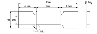
- FIG. 2 is a plan view of a test piece used for evaluating the tensile strength of a silver sintered body according to an embodiment of the present invention.
- 1 is a cross-sectional view schematically illustrating an example of a method for joining metal members using a silver-containing composition according to an embodiment of the present invention.
- 1 is a cross-sectional view schematically illustrating an example of a method for joining metal members using a silver-containing composition according to an embodiment of the present invention.
- 1 is a cross-sectional view schematically illustrating an example of a method for joining metal members using a silver-containing composition according to an embodiment of the present invention.
- FIG. 1 is a cross-sectional view schematically illustrating an example of a method for joining metal members using a silver-containing composition according to an embodiment of the present invention.
- 1 is a cross-sectional view schematically illustrating an example of a method for joining metal members using a silver-containing composition according to an embodiment of the present invention.
- 1 is a cross-sectional view schematically illustrating an example of a method for joining metal members using a silver-containing composition according to an embodiment of the present invention.
- FIG. 3 is a cross-sectional view schematically illustrating another example of a method for joining metal members using a silver-containing composition according to an embodiment of the present invention.
- FIG. 3 is a cross-sectional view schematically illustrating another example of a method for joining metal members using a silver-containing composition according to an embodiment of the present invention.
- FIG. 3 is a cross-sectional view schematically illustrating another example of a method for joining metal members using a silver-containing composition according to an embodiment of the present invention.
- FIG. 3 is a cross-sectional view schematically illustrating another example of a method for joining metal members using a silver-containing composition according to an embodiment of the present invention.
- FIG. 3 is a cross-sectional view schematically illustrating still another example of a method for joining metal members using a silver-containing composition according to an embodiment of the present invention.
- FIG. 3 is a cross-sectional view schematically illustrating still another example of a method for joining metal members using a silver-containing composition according to an embodiment of the present invention.
- FIG. 3 is a cross-sectional view schematically illustrating still another example of a method for joining metal members using a silver-containing composition according to an embodiment of the present invention.
- the silver-containing composition according to an embodiment of the present invention includes primary silver particles having an average particle size of 0.1 ⁇ m or more and less than 0.4 ⁇ m, and secondary silver particles having an average particle size of 0.4 ⁇ m or more and less than 2.3 ⁇ m. and, in the silver-containing composition, the ratio of the total content of the first silver particles and the second silver particles to the total content of all silver particles is 80% by mass or more.
- the silver-containing composition of this embodiment can form a silver sintered body with high tensile strength.
- the silver-containing composition of this embodiment can form a silver sintered body by firing in a wide temperature range, and metal members can be joined with high strength with the silver sintered body interposed therebetween. For example, by using the silver-containing composition of this embodiment, a metal member assembly with high thermal shock resistance can be obtained.
- average particle diameter refers not only to primary silver particles and secondary silver particles, but unless otherwise specified, the term “average particle diameter” refers to particles measured using a scanning electron microscope (SEM). It means the average particle diameter on a volume basis as measured from 200 randomly selected particles by observation and using image analysis software. If the particle observed by SEM is not spherical, the particle diameter is defined as the diameter of a sphere with the same volume as the particle.
- SEM scanning electron microscope
- the ratio of the total content of one or more of the below-mentioned components of the silver-containing composition to the total mass of the silver-containing composition does not exceed 100% by mass.
- the average particle diameter of the first silver particles is 0.1 ⁇ m or more and less than 0.4 ⁇ m, for example, any one of 0.1 to 0.35 ⁇ m, 0.1 to 0.3 ⁇ m, and 0.1 to 0.25 ⁇ m. It may be any of 0.13 to 0.39 ⁇ m, and 0.16 to 0.39 ⁇ m, or 0.13 to 0.35 ⁇ m, 0.16 to 0.3 ⁇ m, and It may be between 0.16 and 0.25 ⁇ m.
- ferrous silver particles with such an average particle size a silver sintered body with higher tensile strength can be formed, and by firing in a wide temperature range, a metal member assembly with higher thermal shock resistance can be obtained. It will be done.
- the number of first silver particles (first silver particles contained in the silver-containing composition) blended in the silver-containing composition may be one type, two or more types, or two or more types. In some cases, their combinations and ratios can be adjusted arbitrarily.
- the average particle diameter of the secondary silver particles is 0.4 ⁇ m or more and less than 2.3 ⁇ m, for example, any one of 0.4 to 1.9 ⁇ m, 0.4 to 1.5 ⁇ m, and 0.4 to 1.1 ⁇ m. It may be any of 0.7 to 2.2 ⁇ m, 1 to 2.2 ⁇ m, and 1.3 to 2.2 ⁇ m, or 0.7 to 1.9 ⁇ m, and 1 It may be between 1.5 ⁇ m and 1.5 ⁇ m.
- ferric silver particles with such an average particle diameter a silver sintered body with higher tensile strength can be formed, and by firing in a wide temperature range, a metal member assembly with higher thermal shock resistance can be obtained. It will be done.
- the number of secondary silver particles (secondary silver particles contained in the silver-containing composition) mixed in the silver-containing composition may be one type, two or more types, or two or more types. In some cases, their combinations and ratios can be adjusted arbitrarily.
- the first silver particles and the second silver particles are each independently coated with one or more organic compounds.
- the organic compound is preferably one or more selected from the group consisting of an alkylamine (monoalkylamine, dialkylamine, or trialkylamine) and a carboxylic acid, and has 8 or less carbon atoms ( It is more preferable to use one or more selected from the group consisting of alkylamines (1 to 8) and carboxylic acids having 8 or less carbon atoms (1 to 8), and n-octylamine, It is more preferable to use one or more selected from the group consisting of -ethylhexylamine and n-hexylamine.
- the first silver particles and the second silver particles may be coated with the organic compound in a state in which they have not reacted with the organic compound, or may be coated with the organic compound in a state in which they have reacted with the organic compound. You can.
- the silver-containing composition may or may not contain other silver particles that are neither primary silver particles nor secondary silver particles.
- the other silver particles include silver particles with an average particle size of less than 0.1 ⁇ m (herein sometimes referred to as “quaternary silver particles”) and silver particles with an average particle size of 2.3 ⁇ m or more. particles (herein sometimes referred to as "tertiary silver particles”).
- Tertiary silver particles tertiary silver particles contained in the silver-containing composition blended in the silver-containing composition and quaternary silver particles (tertiary silver particles contained in the silver-containing composition) blended in the silver-containing composition
- the ratio of the total content of primary silver particles and secondary silver particles to the total content of all silver particles (([Content of primary silver particles in silver-containing composition (parts by mass) ]+[Content of secondary silver particles in the silver-containing composition (parts by mass)])/([Content of primary silver particles in the silver-containing composition (parts by mass)]+[Second silver particle content in the silver-containing composition) Content of silver particles (parts by mass)] + [Content of tertiary silver particles in the silver-containing composition (parts by mass)] + [Content of quaternary silver particles in the silver-containing composition (parts by mass)]) ⁇ 100) is at least 80% by mass, preferably at least 90% by mass, and may be, for example, at least 95% by mass, at least 97% by mass, or at least 99% by mass.
- the ratio is at least the lower limit, a silver sintered body with high tensile strength can be formed, and by firing in a wide temperature range, a metal member assembly with high thermal shock resistance can be obtained.
- the ratio is 100% by mass or less.
- the silver-containing composition does not contain tertiary silver particles, the content of tertiary silver particles in the silver-containing composition is 0 parts by mass.
- the silver-containing composition does not contain quaternary silver particles, the content of quaternary silver particles in the silver-containing composition is 0 parts by mass.
- the ratio of the content of primary silver particles to the total content of all silver particles is preferably 55% by mass or more, for example, 60% by mass or more, 65% by mass or more, and It may be 70% by mass or more.
- the ratio is at least the lower limit, a silver sintered body with higher tensile strength can be formed, and by firing in a wide temperature range, a metal member assembly with higher thermal shock resistance can be obtained.
- the proportion is less than 100% by mass, for example, a silver-containing composition in which the proportion is 80% by mass or less has the effect obtained by containing primary silver particles and the effect obtained by containing secondary silver particles. By containing it, the effects obtained are more well-balanced.
- the silver-containing composition does not contain tertiary silver particles, the content of tertiary silver particles in the silver-containing composition is 0 parts by mass.
- the silver-containing composition does not contain quaternary silver particles, the content of quaternary silver particles in the silver-containing composition is 0 parts by mass.
- the ratio of the content of secondary silver particles to the total content of all silver particles is preferably 10% by mass or more, for example, 20% by mass or more, 30% by mass or more, and It may be 40% by mass or more.
- the ratio is at least the lower limit, a silver sintered body with higher tensile strength can be formed, and by firing in a wide temperature range, a metal member assembly with higher thermal shock resistance can be obtained.
- the ratio is less than 100% by mass, for example, a silver-containing composition in which the ratio is 55% by mass or less has an effect obtained by containing primary silver particles and a silver-containing composition containing secondary silver particles. By containing it, the effects obtained are more well-balanced.
- the silver-containing composition does not contain tertiary silver particles, the content of tertiary silver particles in the silver-containing composition is 0 parts by mass.
- the silver-containing composition does not contain quaternary silver particles, the content of quaternary silver particles in the silver-containing composition is 0 parts by mass.
- the specific surface area of the tertiary silver particles is not particularly limited, but is preferably 0.08 to 0.6 m 2 /g, more preferably 0.1 to 0.5 m 2 /g.
- the specific surface area of the tertiary silver particles can be measured by a known method such as a permeation method or a gas adsorption method using gas molecules such as nitrogen.
- the tap density of the tertiary silver particles is not particularly limited, but is preferably from 3 to 7 mg/m 2 , more preferably from 4 to 6 mg/m 2 .
- the tap density of tertiary silver particles can be measured, for example, in accordance with JIS Z 2512:2012.
- the tertiary silver particles are produced by an atomization method. Unlike silver particles produced by other methods such as chemical reduction methods, such tertiary silver particles typically do not contain organic components that are impurities, or their content is extremely small. Extremely superior in terms of quality.
- the ratio of the content of tertiary silver particles (silver particles with an average particle diameter of 2.3 ⁇ m or more) to the total content of all silver particles is preferably 10% by mass or less, For example, it may be 5% by mass or less, 3% by mass or less, or 1% by mass or less.
- the ratio is below the upper limit, a silver sintered body with higher tensile strength can be formed, and by firing in a wide temperature range, a metal member assembly with higher thermal shock resistance can be obtained.
- the ratio is 0% by mass or more.
- the silver-containing composition does not contain tertiary silver particles, the content of tertiary silver particles in the silver-containing composition is 0 parts by mass.
- the silver-containing composition does not contain quaternary silver particles, the content of quaternary silver particles in the silver-containing composition is 0 parts by mass.
- the ratio of the content of quaternary silver particles (silver particles with an average particle diameter of less than 0.1 ⁇ m) to the total content of all silver particles is preferably 10% by mass or less, For example, it may be 5% by mass or less, 3% by mass or less, or 1% by mass or less.
- the ratio is below the upper limit, a silver sintered body with higher tensile strength can be formed, and by firing in a wide temperature range, a metal member assembly with higher thermal shock resistance can be obtained.
- the ratio is 0% by mass or more.
- the silver-containing composition does not contain tertiary silver particles, the content of tertiary silver particles in the silver-containing composition is 0 parts by mass.
- the silver-containing composition does not contain quaternary silver particles, the content of quaternary silver particles in the silver-containing composition is 0 parts by mass.
- the silver-containing composition contains a solvent in addition to the first silver particles and the second silver particles.
- a silver-containing composition can be made into a paste form and has good handling properties.
- solvent refers to a component that is liquid at room temperature for dissolving a solute, and a component that is liquid at room temperature that functions as a dispersion medium for dispersing dispersoids, unless otherwise specified. It is a concept that encompasses both.
- "normal temperature” means a temperature that is not particularly cooled or heated, that is, a normal temperature, and includes, for example, a temperature of 15 to 25°C.
- the solvent is not particularly limited as long as it can be removed (vaporized) under heating conditions, and the solvent has a high reactivity with components other than the solvent, such as primary silver particles and secondary silver particles in the silver-containing composition. It is preferable to have no.
- the solvent include aromatic hydrocarbons such as toluene, o-xylene, m-xylene, and p-xylene; pentane, hexane, cyclohexane, heptane, octane, cyclooctane, nonane, decane, undecane, dodecane, tridecane, and tetradecane.
- pentadecane, decahydronaphthalene halogenated hydrocarbons such as dichloromethane, chloroform
- esters such as ethyl acetate, monomethyl glutarate, dimethyl glutarate; diethyl ether, tetrahydrofuran (THF), 1,2-dimethoxy Ethers such as ethane (dimethyl cellosolve);
- Ketones such as acetone, methyl ethyl ketone (MEK), and cyclohexanone
- Nitriles such as acetonitrile
- Amides such as N,N-dimethylformamide (DMF) and N,N-dimethylacetamide
- Texanol Examples include alcohol esters (compounds having both a hydroxyl group and an ester bond) such as 2,4-trimethyl-1,3-pentanediol monoisobutyrate).
- the silver-containing composition may contain only one type of solvent, or may contain two or more types of solvents, and when there are two or more types, the combination and ratio thereof can be adjusted as desired.
- the content of the solvent is preferably 5 to 20% by mass, and preferably 10 to 15% by mass, relative to the total mass of the silver-containing composition. It is more preferable that When the ratio is equal to or higher than the lower limit, the effects obtained by using the solvent, such as improved handling of the silver-containing composition, are further enhanced. Excessive use of the solvent is suppressed because the ratio is equal to or less than the upper limit.
- the silver-containing composition does not fall under any of the following categories: primary silver particles, secondary silver particles, tertiary silver particles, quaternary silver particles, and solvents, within a range that does not impair the effects of the present invention. It may contain other ingredients.
- the other components are not particularly limited and can be arbitrarily selected depending on the purpose.
- the silver-containing composition may contain only one type of other components, or may contain two or more types, and when there are two or more types, the combination and ratio thereof can be adjusted as desired. . When the silver-containing composition contains the other components, the content of the other components in the silver-containing composition can be adjusted as appropriate depending on the type of the other components.
- the ratio of the total content of primary silver particles and secondary silver particles to the total content of all components other than the solvent is preferably 80% by mass or more, and 90% by mass. % or more, more preferably 95% by mass or more, for example, it may be 97% by mass or more, or 99% by mass or more.
- the ratio is at least the lower limit, a silver sintered body with higher tensile strength can be formed, and by firing in a wide temperature range, a metal member assembly with higher thermal shock resistance can be obtained.
- the ratio is 100% by mass or less.
- the silver-containing composition includes primary silver particles, secondary silver particles, optionally a solvent, optionally tertiary silver particles, optionally quaternary silver particles, and optionally the above-mentioned. It can be obtained by blending with other ingredients. After blending each component, the resulting blend may be used as it is as a silver-containing composition, or if necessary, a purified product obtained by subsequently performing a known purification operation may be used as a silver-containing composition.
- a method for producing a silver-containing composition As an example of a method for producing a silver-containing composition, primary silver particles having an average particle size of 0.1 ⁇ m or more and less than 0.4 ⁇ m, secondary silver particles having an average particle size of 0.4 ⁇ m or more and less than 2.3 ⁇ m, It has a blending process of blending In the blending step, a method for producing a silver-containing composition may be mentioned, in which the ratio of the total blending amount of the first silver particles and the second silver particles to the total blending amount of all silver particles is 80% by mass or more. .
- a solvent for example, if necessary, a solvent, tertiary silver particles having an average particle diameter of 2.3 ⁇ m or more, and quaternary silver particles having an average particle diameter of less than 0.1 ⁇ m, Other components that do not fall under any of these may or may not be blended with one or more selected from the group consisting of the following.
- each component is not particularly limited. For example, when blending two or more types of ingredients, these two or more types of ingredients may be added separately, or these two or more types of ingredients may be mixed in advance and this mixture may be added. good.
- the mixing method is not particularly limited, and may include mixing by rotating a stirring bar or stirring blade; mixing using a mixer, triple roll, kneader, bead mill, etc.; mixing by applying ultrasonic waves, etc.
- An appropriate method may be selected from known methods.
- non-dispersed material refers to a mixture of a solvent-insoluble component and a solvent, the amount of the solvent is relatively small, and the solvent-insoluble component is not in a dispersed state.
- a preferred method of blending first silver particles, second silver particles, and a solvent a mixture of a powder of first silver particles and a solvent, and a mixture of a powder of first silver particles and a solvent are mixed. Examples include a blending method of mixing a mixture of a powder and a solvent, and the mixture may be either a dispersion or a non-dispersion.
- the temperature during blending is not particularly limited as long as each blended component does not deteriorate, but it is preferably -5 to 40°C.
- the temperature at the time of blending may be appropriately adjusted depending on the types and amounts of the ingredients to be blended so that the resulting mixture has a viscosity that is easy to stir.
- the blending time is also not particularly limited as long as each blended component does not deteriorate, but it is preferably 10 minutes to 24 hours.
- the resulting mixture tends to clump after all of these components are blended, and the composition tends to become uneven. Therefore, for example, it is preferable that the mixture obtained by blending all the components is stirred and defoamed twice or more, and after the resulting mixture is ground, the mixture is stirred and defoamed again. By doing so, a silver-containing composition having a uniform composition can be obtained.
- the silver-containing composition can be used for joining metal members (manufacturing a joined metal member).
- a silver sintered body can be formed by firing in a wide temperature range, and metal members can be joined with high strength with the silver sintered body interposed therebetween.
- the first silver particles first silver particles having an average particle diameter of 0.1 ⁇ m or more and less than 0.4 ⁇ m
- the second silver particles first silver particles having an average particle diameter of 0.4 ⁇ m
- a silver-containing composition containing secondary silver particles having a diameter of less than 2.3 ⁇ m
- first metal member herein sometimes simply referred to as a “first member”.
- a joining method includes a step (C) of joining the first member and the second member using the silver sintered body.
- the first member is made of metal, and the metal constituting it may be either a single metal or an alloy.
- Preferred examples of the metals include copper, silver, gold, palladium, nickel, and alloys containing one or more selected from the group consisting of copper, silver, gold, palladium, and nickel. .
- the metal is more preferably copper, silver, gold, palladium, or nickel, and even more preferably copper or silver.
- a metal member further provided with a metal layer on the surface may be used as the member including the first member.
- the metal layer can be formed on the surface of the metal member by, for example, a known method such as vapor deposition or plating.
- the part to which the silver-containing composition is attached becomes the first member.
- the metal layer becomes the first member.
- both the metal member and the metal layer become the first member.
- the silver-containing composition is applied only to a metal member, the metal member becomes the first member.
- a preferred metal member having such a metal layer on its surface is, for example, a metal layer comprising a copper member and one or more metal layers provided on the surface of the copper member.
- a metal layer comprising a copper member and one or more metal layers provided on the surface of the copper member.
- An example of this includes a copper member, a titanium layer provided on the surface of the copper member, and a silver layer provided on the surface of the titanium layer opposite to the copper member.
- Examples include a copper member with a metal layer.
- a composite of a metal member and a non-metal member may be used as the member including the first member.
- the nonmetallic member include a semiconductor wafer, a semiconductor chip, an organic insulating base material, an inorganic insulating base material, an organic/inorganic composite insulating base material, and any of these may be known.
- Examples of the semiconductor wafer or semiconductor chip include wafers or chips made of a semiconductor such as silicon, silicon carbide, or gallium nitride.
- Examples of the organic insulating base material include a polytetrafluoroethylene (PTFE) base material, a polyimide base material, a liquid crystal polymer base material, a cycloolefin polymer base material, and the like.
- Examples of the inorganic insulating base material include ceramic base materials.
- the organic/inorganic composite insulating base material is a base material whose constituent materials are both an organic material and an inorganic material, and examples thereof include a glass epoxy resin base material.
- the composite may be formed by forming a metal member at a desired location of the non-metallic member by vapor deposition, plating, sputtering, printing, etc., or by brazing. Alternatively, it can be produced by joining metal members by bonding with an adhesive or the like.
- metal members provided on semiconductor wafers, semiconductor chips, organic insulating base materials, inorganic insulating base materials, organic/inorganic composite insulating base materials, etc.
- a metal plate for example, a heat sink
- the shape of the first member is not particularly limited, and examples thereof include a sheet, a plate, a prism, a pyramid, a cylinder, a cone, a sphere, a long sphere, and a rod. , prismatic, pyramidal, cylindrical, conical, spherical, spheroidal, and rod-like), and may be a combination or fusion of two or more types selected from the group consisting of .
- the size of the first member is not particularly limited.
- the shape and size of the first member can be appropriately selected depending on the use of the first member.
- the length of one side of the joint surface (first surface described later) of the first member is 0.01 to 30 mm, 0.02 to 26 mm, and
- the thickness of the first member may be any one of 0.03 to 22 mm, and the thickness of the first member may be any one of 0.01 to 7 mm, 0.02 to 5 mm, and 0.03 to 3 mm.
- the first member having these shapes and sizes is suitable, for example, as a component such as an electrode forming a circuit. If the shape of the first member is neither plate-like nor rod-like, for example, the first member is made so that the area of the joint surface is equal to the area of the joint surface calculated from the length of one side described above. The size of one member can be adjusted.
- the silver-containing composition is attached to the first member.
- the method for attaching the silver-containing composition to the first member include known methods such as a printing method and a coating method.
- Examples of the printing method include a screen printing method, a flexo printing method, an offset printing method, a dip printing method, an inkjet printing method, a dispenser printing method, a jet dispenser printing method, a gravure printing method, a gravure offset printing method, Examples include pad printing method.
- the coating method includes, for example, a method using various coaters such as a spin coater, an air knife coater, a curtain coater, a die coater, a blade coater, a roll coater, a gate roll coater, a bar coater, a rod coater, and a gravure coater; Methods to be used include a method using a coating device such as a slot die, a spray method, and the like.
- various coaters such as a spin coater, an air knife coater, a curtain coater, a die coater, a blade coater, a roll coater, a gate roll coater, a bar coater, a rod coater, and a gravure coater
- Methods to be used include a method using a coating device such as a slot die, a spray method, and the like.
- the portion of the first member to which the silver-containing composition is attached may be subjected to a cleaning treatment to remove impurities before the silver-containing composition is attached. By doing so, a metal member assembly with higher thermal shock resistance can be obtained.
- the cleaning treatment can be performed by a known method, and may be, for example, a chemical treatment of the surface using a drug or a physical treatment using a surface treatment.
- the chemicals include acids such as nitric acid, phosphoric acid, sulfuric acid, and hydrochloric acid; organic solvents such as acetone.
- Chemical treatment with acids is useful for general impurity removal. When an acid is used, it is preferable to further wash the acid-treated portion (acid-treated surface) of the first member with water. Chemical treatment with organic solvents is useful when removing highly fat-soluble impurities.
- the surface treatment include polishing using an abrasive material such as a file.
- the amount of the silver-containing composition deposited on the first member is not particularly limited, and may be appropriately set in consideration of the desired thickness of the silver sintered body.
- a heated object of the silver-containing composition is obtained by heating the silver-containing composition adhered to the first member.
- silver particles such as primary silver particles and secondary silver particles are not sintered at all or are only partially sintered but not completely sintered. (at least a portion is unsintered), and has changed to a state suitable for forming a silver sintered body, which will be described later.
- heating the silver-containing composition causes part or all of the volatile component to be removed from the heated silver-containing composition by vaporization. .
- the mass of the heated silver-containing composition becomes less than the mass of the silver-containing composition before heating, and a decrease in the mass of the silver-containing composition is observed.
- either one or both of the primary silver particles and secondary silver particles are in the form of particles.
- the particles may maintain their shape, or the particles may be fused to each other.
- the silver-containing composition further contains one or both of tertiary silver particles and quaternary silver particles, the silver-containing composition may contain volatile components such as solvents.
- either one or both of the tertiary silver particles and the quaternary silver particles may maintain a particulate shape, or the particles may be fused to each other. You can.
- step (B) the silver particles may or may not be necked.
- the heating temperature of the silver-containing composition deposited on the first member is preferably 140°C or higher, and may be, for example, either 160°C or higher or 200°C or higher.
- the heating temperature is equal to or higher than the lower limit, a silver sintered body with higher tensile strength can be formed, and by firing in a wide temperature range, a metal member assembly with higher thermal shock resistance can be obtained.
- the upper limit of the heating temperature is not particularly limited.
- the heating temperature is preferably 250° C. or less, in order to increase the thermal shock resistance of the metal member assembly formed by joining the first member and the second member described below.
- the temperature may be either 200°C or lower or 155°C or lower.
- the heating temperature may be, for example, any of 140 to 250°C, 160 to 250°C, and 200 to 250°C, or any of 140 to 200°C, and 160 to 200°C.
- the temperature may be 140 to 155°C.
- heating temperatures of, for example, 160 to 250°C, 200 to 250°C, and 160 to 200°C are suitable for causing necking between silver particles.
- a heating temperature of 140 to 155° C. is suitable for heating without necking the silver particles together.
- the heating time of the silver-containing composition at a temperature of 140° C. or higher is not particularly limited, but is preferably 2 to 40 minutes, for example, 2 to 40 minutes. -20 minutes, 10-40 minutes, and 10-20 minutes.
- the heating time is at least the lower limit, a silver sintered body with higher tensile strength can be formed, and by firing in a wide temperature range, a metal member assembly with higher thermal shock resistance can be obtained.
- the heating time By setting the heating time to be less than or equal to the upper limit value, it is possible to prevent the heating time from becoming excessive.
- the heating temperature When heating the silver-containing composition at a temperature of 140° C. or higher, the heating temperature may be constant or substantially constant, or it may be varied. When the heating temperature is varied, the heating temperature may be increased consistently (in other words, it is not necessary to keep it constant, keep it substantially constant, and decrease it). However, a time period may be provided in which the temperature is kept constant or substantially constant, or a time period in which the temperature is decreased may be provided. Among these, it is preferable that the heating temperature is always raised or kept constant or substantially constant (in other words, not lowered at all).
- heating the silver-containing composition at a substantially constant temperature refers to heating the silver-containing composition while suppressing fluctuations in heating temperature to within 3°C, regardless of the heating temperature range. means.
- step (B) it is preferable that the first member to which the silver-containing composition is attached is directly heated at a portion to which the silver-containing composition is not attached. By doing so, the effect of suppressing unintended deterioration of the silver-containing composition becomes higher.
- the silver-containing composition can be heated by known methods such as heating with an electric furnace, heating with a thermosensitive thermal head, heating with far-infrared irradiation, heating with spraying of high-temperature gas, heating with high-frequency irradiation, and dielectric heating. .
- step (B) the temperature at the start of heating the silver-containing composition may be, for example, room temperature.
- the heating rate when heating the silver-containing composition after starting heating of the silver-containing composition until obtaining the heated silver-containing composition is not particularly limited, and is, for example, 5 to 5. It may be any one of 50°C/min, 5 to 30°C/min, and 5 to 16°C/min.
- Heating of the silver-containing composition may be performed under normal pressure, reduced pressure, or increased pressure, regardless of the heating temperature of the silver-containing composition, but heating is preferably performed under normal pressure. Heating of the silver-containing composition may be performed, for example, either in the air atmosphere or in an inert gas atmosphere, regardless of the heating temperature of the silver-containing composition.
- the inert gas include nitrogen gas, argon gas, helium gas, and the like.
- the thickness of the heated silver-containing composition is not particularly limited, and may be appropriately set in consideration of the desired thickness of the silver sintered body, which will be described later.
- the thickness of the heated silver-containing composition is preferably, for example, 50 ⁇ m or more, and may be, for example, any one of 100 ⁇ m or more, 200 ⁇ m or more, or 300 ⁇ m or more.
- the upper limit of the thickness of the heated object is not particularly limited.
- the thickness of the heating object is preferably 500 ⁇ m or less.
- the thickness of the heated object may be, for example, any one of 50 to 500 ⁇ m, 100 to 500 ⁇ m, 200 to 500 ⁇ m, and 300 to 500 ⁇ m. However, these are examples of the thickness of the heated object.
- the thickness of the heated object can be adjusted, for example, by adjusting the amount of the silver-containing composition deposited on the first member.
- the heated material of the silver-containing composition may have one layer or two or more layers, and when there are two or more layers, the combination and ratio thereof may be determined depending on the purpose. You can adjust it as you like.
- the heated object of the silver-containing composition has two or more layers, the total thickness of each layer can be set to the above-mentioned preferred thickness of the heated object.
- the heating object having two or more layers can be handled in the same way as the heating object having one layer.
- step (B) the silver-containing composition adhered to the first member is heated at a constant or substantially constant temperature of less than 140°C (in this specification, this heating is referred to as “preheating”). It is preferable to obtain a heated silver-containing composition by heating at a temperature of 140° C. or higher (herein, this heating may be referred to as “main heating”).
- the preheating is performed at a temperature of less than 140° C., and part or all of volatile components such as solvents in the silver-containing composition are vaporized in advance and removed from the silver-containing composition (i.e., dried). By doing so, when the main heating is performed at a temperature of 140° C.
- the vaporization of volatile components can be prevented or the amount of vaporization can be reduced in the silver-containing composition after preheating, and the amount of vaporization caused by the vaporization of volatile components can be prevented. Foaming of the silver-containing composition can be suppressed. As a result, it is possible to suppress the surface roughness of the heated silver-containing composition formed on the first member, and finally, it is possible to form a silver sintered body with higher tensile strength, and by firing in a wide temperature range, A metal member assembly with higher thermal shock resistance can be obtained.
- the heating temperature of the silver-containing composition during preheating is preferably 50 to 90°C, for example, 50 to 75°C, 65 to 90°C. , and 65 to 75°C.
- the heating temperature during preheating is equal to or higher than the lower limit, foaming of the silver-containing composition during main heating can be further suppressed.
- the heating temperature during preheating is equal to or lower than the upper limit value, foaming of the silver-containing composition during preheating can be suppressed.
- the heating time of the silver-containing composition during preheating (that is, the time for heating the silver-containing composition at a constant or substantially constant temperature of less than 140 ° C.) is not particularly limited, but is preferably 5 to 60 minutes. , for example, 20 to 60 minutes, 5 to 40 minutes, or 20 to 40 minutes.
- the heating time during preheating is equal to or greater than the lower limit, foaming of the silver-containing composition during main heating can be further suppressed.
- the heating time during preheating is less than or equal to the upper limit value, it is possible to prevent the preheating time from becoming excessive.
- Preheating can be performed under the same conditions as in the case of heating the silver-containing composition at a temperature of 140 ° C. or higher (i.e., main heating), except for the above-mentioned heating temperature and heating time. .
- Step (C)> In the step (C) of the bonding method, the heated material of the silver-containing composition is interposed, and the heated material is fired while the first member and the second metal member are pressed together. As a result, the first member and the second member are joined by the silver sintered body at the same time as the silver sintered body is formed. As a result, the desired metal member assembly is obtained.
- the silver sintered body can be used as a conductive joint.
- the second member is also made of metal.
- Examples of the metal constituting the second member include the same metals as the metal constituting the first member.
- Examples of the shape of the second member include those similar to the shape of the first member.
- the size of the second member may be similar to the size of the first member.
- the second member can also be used as a member that includes the second member.
- the member including the second member can be used in the same manner as the member including the first member described above.
- the first member and the second member may be the same or different from each other.
- the first member and the second member may be the same or different in terms of material, shape, and size.
- preferred second members include, for example, parts such as electrodes that constitute a circuit.
- step (C) a pressure in a direction from the first member toward the second member and a pressure applied to the composite in which the first member, the heated object, and the second member are laminated in this order are applied.
- a pressure in a direction from the first member toward the second member and a pressure applied to the composite in which the first member, the heated object, and the second member are laminated in this order are applied.
- the above-mentioned pressure in two directions may be applied by a known method.
- fix the composite on a horizontal surface with the surface of either the first member or the second member facing downward in the vertical direction By placing the other surface of the first member and the second member vertically upward and placing a weight thereon, pressure can be applied to the composite from only one direction.
- pressure is applied by placing a weight on either the first member or the second member, but pressure may be applied by other pressing means.
- a case has been described in which the composite is arranged with the surfaces of the first member and the second member facing in the vertical direction. A composite may also be placed.
- the pressure (in this specification, sometimes abbreviated as "crimping pressure") when pressing the first member and the second member with each other with the heating object interposed is not particularly limited, but is 5 MPa or more. It is preferable that the pressure is 8 MPa or more, or 11 MPa or more, for example.
- the upper limit of the crimp pressure is not particularly limited. In terms of avoiding excessive crimping, the crimping pressure is preferably 25 MPa or less, and may be, for example, either 22 MPa or less or 19 MPa or less.
- the crimping pressure may be, for example, any one of 5 to 25 MPa, 8 to 25 MPa, and 11 to 25 MPa, or any one of 5 to 22 MPa, 8 to 22 MPa, and 11 to 22 MPa. or may be any one of 5 to 19 MPa, 8 to 19 MPa, and 11 to 19 MPa.
- the crimping pressure may be constant from the start of crimping to the end of crimping, or may be varied instead of being constant.
- the crimp pressure may be increased consistently (in other words, it is not necessary to keep it unchanged or decrease it), or set a period of time during which it is not changed. Alternatively, a period of time may be provided for the reduction. Among these, it is preferable that the compression pressure be always increased or not changed (in other words, not decreased at all).
- the firing of the heated object can be performed by further heating the heated object.
- the heating at this time can be performed in the same manner as the heating performed on the silver-containing composition in step (B).
- the temperature at which heating is started for firing the heated object may be, for example, room temperature, which is lower than the temperature of the heated object at the end of step (B). ) may be equal to or higher than the temperature of the heated object at the end of step (2).
- the firing temperature of the heated object is preferably 250°C or higher, and may be, for example, either 270°C or higher or 290°C or higher.
- the upper limit of the firing temperature is not particularly limited.
- the firing temperature is preferably 350°C or lower, and may be either 330°C or lower or 310°C or lower. .
- the firing temperature may be, for example, 250-350°C, 270-350°C, and 290-350°C, or 250-330°C, 270-330°C, and 290-330°C.
- the temperature may be any of 330°C, 250 to 310°C, 270 to 310°C, and 290 to 310°C. However, these are examples of the firing temperatures.
- a silver sintered body with high tensile strength can be formed, and metal members can be joined with high strength by interposing such a silver sintered body by firing the heated material in a wide temperature range.
- metal members can be joined with high strength by interposing such a silver sintered body by firing the heated material in a wide temperature range.
- the heated object is fired separately at two or more different firing temperatures within the numerical ranges exemplified above (e.g., 250°C or higher and 350°C or lower)
- the tensile strength of the silver sintered body is high, and the thermal shock resistance of the metal member joined body is high.
- the temperature difference between two or more firing temperatures at which such an effect can be obtained is, for example, preferably 20°C or higher, more preferably 30°C or higher, and even more preferably 40°C or higher.
- the rate of temperature increase when raising the temperature of the heated object between the start of heating for firing the heated object and the end of the firing of the heated object is not particularly limited, but is 5 to 50%.
- the temperature is preferably 5°C/min, more preferably 5 to 40°C/min, even more preferably 5 to 30°C/min.
- the firing time of the heated object is not particularly limited, but is preferably 1 minute to 12 hours, and may be, for example, 5 minutes to 4 hours, or 10 minutes to 1 hour.
- the firing time is at least the lower limit, a silver sintered body with higher tensile strength can be formed, and a metal member joined body with higher thermal shock resistance can be obtained.
- the firing temperature When firing the heated object, the firing temperature may be constant or substantially constant, or different from these, it may be varied. When varying the firing temperature, the firing temperature may be consistently increased (in other words, it may not be constant, substantially constant, or decreased). However, a time period may be provided in which the temperature is kept constant or substantially constant, or a time period in which the temperature is decreased may be provided. Among these, it is preferable that the firing temperature is always increased or kept constant or almost constant (in other words, not decreased at all). For example, after consistently increasing the firing temperature, the maximum reached there The temperature may be maintained for a certain period of time until the end of step (C). In that case, the time for maintaining the firing temperature of the heated material for a certain period of time is preferably 1 to 60 minutes, and may be, for example, either 1 to 40 minutes or 1 to 20 minutes.
- firing the heated material of the silver-containing composition at a substantially constant temperature means firing the heated material while suppressing fluctuations in the firing temperature to within 3°C, regardless of the firing temperature range. It means that.
- the heating material may be fired under normal pressure, under reduced pressure, or under increased pressure.
- the heating material may be fired, for example, in an air atmosphere or an inert gas atmosphere.
- the inert gas include nitrogen gas, argon gas, helium gas, and the like.
- step (C) (X1) the firing of the heated material may be started after starting the compression bonding between the first member and the second member. )"), and (X2) after starting the firing of the heated material, pressing the first member and the second member may be started (herein referred to as “pressing firing”). (X3) Pressing the first member and the second member and firing the heated material may be started at the same time (herein referred to as “method (X2)").
- the timing of starting the above-mentioned pressing and firing can be arbitrarily selected.
- the thickness of the silver sintered body is preferably 10 ⁇ m or more, and may be, for example, 50 ⁇ m or more, 90 ⁇ m or more, or 130 ⁇ m or more. When the thickness of the silver sintered body is equal to or greater than the lower limit value, the thermal shock resistance of the metal member assembly becomes higher.
- the upper limit of the thickness of the silver sintered body is not particularly limited. For example, in terms of easier formation of the silver sintered body, the thickness of the silver sintered body is preferably 300 ⁇ m or less, and may be, for example, 250 ⁇ m or less.
- the thickness of the silver sintered body may be, for example, 10 to 300 ⁇ m, 50 to 300 ⁇ m, 90 to 300 ⁇ m, and 130 to 300 ⁇ m, or 10 to 250 ⁇ m, 50 to 250 ⁇ m, It may be either 90 to 250 ⁇ m or 130 to 250 ⁇ m. However, these are examples of the thickness of the silver sintered body.
- the "thickness of the silver sintered body” means the thickness of the silver sintered body in the joining direction of the first member and the second member.
- the thickness of the silver sintered body is determined, for example, by the thickness of the heated object before firing.
- the thickness of the silver sintered body is, for example, preferably 20 to 60%, 20 to 35%, or 35 to 60% of the thickness of the heated object before firing. Good too. However, these are examples of the relationship between the thickness of the silver sintered body and the thickness of the heated object before firing.
- the tensile strength of the silver sintered body in the metal member assembly obtained in this embodiment can be determined, for example, by performing a tensile test on a test piece of the silver sintered body, as described later in Examples. can be evaluated by the measured value of the maximum stress of the test piece (silver sintered body).
- the maximum stress of the test piece can be measured, for example, by the method shown below. That is, a test piece having the same composition as the silver sintered body is prepared, the width of which is 5 mm, the length of the measurement target portion is 6 mm, and the thickness is 0.1 mm. For this purpose, for example, using the same silver-containing composition as in the case of the silver sintered body in the metal member assembly whose tensile strength is to be evaluated, and using the same method, separately prepare the above-mentioned size (5 mm width, measured A silver sintered body having a length of 6 mm and a thickness of 0.1 mm (target portion) was prepared and used as a test piece.
- test speed tensile speed
- maximum value of the measured stress of the test piece at this time is determined. is adopted as the maximum stress.
- An example of a plan view of the test piece is shown in FIG.
- the maximum stress of the test piece is preferably 100 MPa or more, and may be, for example, either 110 MPa or more or 120 MPa or more. It can be evaluated that the larger the maximum stress of the test piece, the higher the tensile strength of the silver sintered body.
- the upper limit of the maximum stress of the test piece is not particularly limited.
- the maximum stress of the test piece is preferably 200 MPa or less, for example, 170 MPa or less, in terms of easier joining of the first member and the second member (manufacturing the metal member joined body more easily). or less, or 140 MPa or less.
- the maximum stress of the test piece may be, for example, 100-200 MPa, 110-200 MPa, and 120-200 MPa, or 100-170 MPa, 110-170 MPa, and 120-170 MPa. It may be any one of 100 to 140 MPa, 110 to 140 MPa, and 120 to 140 MPa. However, these are examples of the maximum stress of the test piece.
- An example of a preferable metal member assembly is a metal member assembly in which a first metal member and a second metal member are joined by a silver sintered body, and the silver A sintered body is formed by firing the silver-containing composition according to an embodiment of the present invention described above, As a test piece having the same composition as the silver sintered body, a test piece having a width of 5 mm, a length of the measurement target part of 6 mm, and a thickness of 0.1 mm was prepared.
- the first member and the second member are either the metal member or the metal layer of a metal member with a metal layer comprising a metal member and a metal layer provided on the surface of the metal member.
- Examples include a metal member assembly that is one or both of the metal members, or the metal member in a composite of a metal member and a non-metal member.
- a more preferable example of a metal member assembly is a metal member assembly in which a first metal member and a second metal member are joined by a silver sintered body, A silver sintered body is formed by firing the silver-containing composition according to an embodiment of the present invention described above, As a test piece having the same composition as the silver sintered body, a test piece having a width of 5 mm, a length of the measurement target part of 6 mm, and a thickness of 0.1 mm was prepared.
- the first member is the silver film of a metal base material with a silver film comprising a metal base material and a silver film provided on the surface of the metal base material, Metal member joining, wherein the second member is the silver film in a composite of a semiconductor wafer, a semiconductor chip, an organic insulating base material, an inorganic insulating base material, or an organic/inorganic composite insulating base material, and a silver film.
- the metal base material is a copper base material.
- the semiconductor wafer, semiconductor chip, organic insulating base material, inorganic insulating base material, or organic/inorganic composite insulating base material is a wafer or chip made of silicon, silicon carbide, or gallium nitride, or polytetrafluoroethylene. It is preferable to use a substrate made of polyimide, a substrate made of liquid crystal polymer, a substrate made of cycloolefin polymer, a substrate made of ceramic, or a substrate made of glass epoxy resin.
- the joining method may include other steps (in this specification, (sometimes referred to as "other step (1)").
- the other step (1) is not particularly limited and can be arbitrarily selected depending on the purpose.
- the timing of performing the other step (1) can also be arbitrarily selected depending on the purpose, for example, before step (A), between step (A) and step (B), or between step (B) and step (C). ) or after step (C).
- FIGS. 1 to 2F are cross-sectional views for schematically explaining an example of the joining method.
- a description will be given of the joining method (sometimes referred to as "joining method-1" in this specification) when the compression firing method (X1) is adopted in step (C).
- the figures used in the following explanation may show important parts enlarged for convenience in order to make it easier to understand the features of the present invention, and the dimensional ratio of each component may be the same as the actual one. Not necessarily.
- first silver particles first silver particles having an average particle diameter of 0.1 ⁇ m or more and less than 0.4 ⁇ m
- a silver-containing composition 130 containing particles secondary silver particles having an average particle diameter of 0.4 ⁇ m or more and less than 2.3 ⁇ m
- first surface one surface of the plate-shaped first member 11.
- step (B) of the bonding method-1 by heating the silver-containing composition 130 attached to the first member 11, a heated object 130' of the silver-containing composition is obtained as shown in FIG. 2B. .
- step (C) of the joining method-1 first, as shown in FIG. 2C, a laminated structure of the first member 11, the heated object 130', and the second member 12 is produced. At this time, a surface 12a of the second member 12 on the first member 11 side (herein sometimes referred to as a "first surface") comes into contact with the heated object 130'.
- step (C) of the joining method-1 as shown in FIG. 2D, the crimping of the laminated structure is started.
- the force applied to press the laminated structure may be one or both of force P1 and force P2 .
- step (C) of the joining method-1 firing of the heated object 130' in the laminated structure is started.
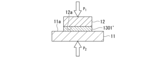
- the heated object in the middle of firing before becoming a silver sintered body is designated by the reference numeral 1301'.
- the first member 11 and the second member 12 are pressed together with the heated material 130' made of a silver-containing composition interposed therebetween, and the heated material 130' is fired, as shown in FIG. 2F.
- the silver sintered body 13 is formed from the heated object 130' through the heated object 1301' in the middle of firing, and at the same time, the first member 11 and the second member 12 are connected to the silver sintered body 13. Join by. As a result, the desired metal member assembly 1 is obtained.
- FIG. 3A to 3D are cross-sectional views for schematically explaining other examples of the joining method.
- the joining method (sometimes referred to as “joining method-2" in this specification) in the case where the compression firing method (X2) is adopted in step (C) will be described.
- the same components as those shown in the already explained figures are given the same reference numerals as in the already explained figures, and detailed explanation thereof will be omitted.
- the steps (A) and (B) of the bonding method-2 are the same as the steps (A) and (B) of the bonding method-1, so the description thereof will be omitted.
- step (C) of the joining method-2 first, as shown in FIG. 3A, a laminated structure of the first member 11, the heated object 130', and the second member 12 is produced. This is the same as in the case of joining method-1.
- step (C) of the bonding method-2 firing of the heated object 130' in the laminated structure is started.
- the heating object 130' is shown as the heating object 1301' in the middle of firing.
- step (C) of the joining method-2 as shown in FIG. 3C, a laminated structure of the first member 11, the heated object 1301' in the middle of firing, and the second member 12 is formed. Start crimping.
- the first member 11 and the second member 12 are pressed together with the heated material 130' made of a silver-containing composition interposed therebetween, and the heated material 130' is fired, as shown in FIG. 3D.
- the first member 11 and the second member 12 are joined by the silver sintered body 13.
- the desired metal member assembly 1 similar to that shown in FIG. 2F is obtained.
- FIGS. 4A to 4C are cross-sectional views for schematically explaining still other examples of the joining method.
- a description will be given of the joining method (sometimes referred to as "joining method-3" in this specification) when the compression firing method (X3) is adopted in step (C).
- the steps (A) and (B) of the bonding method-3 are the same as the steps (A) and (B) of the bonding method-1, so the explanation thereof will be omitted.
- step (C) of the joining method-3 first, as shown in FIG. 4A, a laminated structure of the first member 11, the heated object 130', and the second member 12 is produced. This is the same as in the case of joining method-1.
- step (C) of the joining method-3 the press-bonding of the first member 11 and the second member 12 and the firing of the heated object 130' in the laminated structure are started simultaneously.
- FIG. 4B shows a state in which the heated object 130' has become the heated object 1301' in the middle of firing.
- a silver sintered body includes primary silver particles (primary silver particles having an average particle size of 0.1 ⁇ m or more and less than 0.4 ⁇ m) and secondary silver particles (primary silver particles having an average particle size of 0.1 ⁇ m or more and less than 0.4 ⁇ m).
- a test piece with a length of 6 mm and a thickness of 0.1 mm was prepared, and a tensile test was conducted in which the test piece was pulled in the length direction at a test speed of 1 ⁇ 10 -4 /s, The maximum stress of the test piece is 100 MPa or more.
- the silver sintered body of this embodiment can be formed by using the silver-containing composition according to one embodiment of the present invention described above.
- the silver sintered body of this embodiment thus has high tensile strength, as determined by the maximum stress in the tensile test of the test piece.
- Such a silver sintered body can be realized in a metal member assembly having high thermal shock resistance by firing in a wide temperature range.
- the specific maximum stress of the silver sintered body or the test piece of this embodiment and the method of measuring the maximum stress are as described above.
- the silver sintered body of this embodiment can be formed by heating and firing the silver-containing composition, for example, by the above-mentioned joining method. Therefore, a description of the method for manufacturing the silver sintered body of this embodiment will be omitted.
- Example 1 When the firing temperature is 255°C ⁇ Manufacture of silver-containing composition>> At room temperature, primary silver particles (average particle diameter 0.19 ⁇ m) (67 parts by mass as primary silver particles) made into a dispersion with Texanol and secondary silver particles (average particle diameter) made into a dispersion with Texanol 0.49 ⁇ m) (33 parts by mass as ferric silver particles) is placed in a bottle, the mixture in the bottle is stirred for 30 seconds using a stirring defoaming machine, and then defoamed for 30 seconds. was repeated three times.
- a paste-like silver-containing composition was obtained by carrying out one stirring and defoaming treatment in which the mixture was stirred for seconds and then defoamed for 30 seconds.
- the content ratio of the solvent (Texanol) to the total mass of the silver-containing composition was 13.3% by mass.
- a copper base material with a size of 20 mm x 20 mm x 2 mm and a silicon carbide (SiC) chip with a size of 4.7 mm x 4.7 mm x 0.3 mm were prepared.
- a titanium film (thickness: 0.1 ⁇ m) and a silver film (thickness: 5 ⁇ m) are applied in this order to the entire surface of the copper base material to be bonded and the entire surface of the silicon carbide chip to be bonded, respectively, by plating treatment. By laminating them, a copper base material with a plating film and a silicon carbide chip with a plating film were produced.
- the silver-containing composition obtained above was printed onto the silver film (in other words, the plating film) in the copper base material with the plating film by a screen printing method, so that the size of the silver-containing composition was 5 mm x 5 mm x 0.3 mm.
- a printed layer was formed (step (A)).
- the silicon carbide chip with a plating film is placed on the heating object of the printing layer provided on the copper substrate with the plating film, with the silver film (in other words, the plating film) therein facing the heating object side. I posted it towards.
- the silver film in other words, the plating film
- the silicon carbide chip with the plating film was aligned so that the outer periphery of the silicon carbide chip with the film was in equilibrium.
- the obtained laminate was heated to room temperature at a heating rate of 15°C/min while being pressed at a pressure of 15 MPa in the stacking direction of the copper base material and the silicon carbide chip using a heat press machine.
- the temperature was raised from 255° C. to 255° C., and maintained at 255° C. for 10 minutes to bake the heated printed layer.
- a silver sintered body was formed, and the plated copper base material and the plated silicon carbide chip were joined by the silver sintered body (step (C)).
- the temperature of the bonded body obtained above was lowered to room temperature by water-cooling the heat press machine and lowering the stage temperature to room temperature, and then the pressurization of the laminate (joint body) was released.
- the area that appears black in the area is the silver sintered body (junction) that is in close contact with the silver film, so the area that appears black is the area of the surface of the silicon carbide chip on the silver sintered body side.
- Calculate the area ratio of the area [Area of the area that looks black in the area on the silver sintered body side from the silicon carbide chip] / [Area of the surface of the silicon carbide chip on the silver sintered body side] x 100), and use this as the initial bonding.
- the initial adhesion of the metal member assembly was evaluated according to the following criteria.The results are shown in Table 1. (Evaluation criteria) A: The initial bonding rate is 95% or more, and the initial adhesion of the metal member joined body is high. B: The initial bonding rate is less than 95%, and the initial adhesion of the metal member joined body is insufficient.
- thermal shock resistance of metal member assembly The metal member assembly for which the initial bonding rate was calculated above was placed in a thermal shock tester ("TSA-71L-A” manufactured by ESPEC), left undisturbed for 30 minutes under heating conditions of 150°C, and then for 2 minutes. After that, let it stand for 30 minutes under cooling conditions of -40 ° C., this is considered as one cycle, and from 2 minutes after that, let it stand under the same heating conditions and leave it under cooling conditions, A thermal shock test was conducted by repeating the heating/cooling cycle 299 times and repeating this heating/cooling cycle a total of 300 times.
- TSA-71L-A manufactured by ESPEC
- the metal member assembly is taken out from the thermal shock tester, and as in the case of the initial bonding rate (%) described above, the area of the black region described above is calculated based on the area of the surface of the silicon carbide chip on the silver sintered body side. The ratio was calculated, and this was adopted as the bonding rate (%) after the thermal shock test. Then, the thermal shock resistance of the metal member assembly was evaluated according to the following criteria. The results are shown in Table 1. (Evaluation criteria) A: The bonding rate after the thermal shock test is 85% or more, and the thermal shock resistance of the joined metal member is high. B: The bonding rate after the thermal shock test is less than 85%, and the thermal shock resistance of the joined metal member is insufficient.
- the silver-containing composition obtained above was coated on one side of a stainless steel (SUS) plate with a size of 50 mm x 40 mm x 1.1 mm by a screen printing method, with a size of 43 mm x 31 mm x 0.5 mm. A printed layer of 25 mm was formed.
- SUS stainless steel
- the heated printed layer obtained was allowed to cool until its temperature reached room temperature, and then peeled off from the SUS plate.
- the heated printed layer after being peeled off from the SUS plate was heated from room temperature at a temperature increase rate of 10° C./min while pressurizing the printed layer at a pressure of 15 MPa in the thickness direction. The temperature was raised to 300° C. and maintained at 300° C. for 10 minutes to bake the heated printed layer.
- the temperature of the fired product obtained above was lowered to room temperature by cooling the precision heating and pressurizing device with water and lowering the stage temperature to room temperature, and then the pressurization of the fired product was released. Through the above steps, a silver sintered body (thickness: 0.1 mm) was obtained.
- the value obtained by dividing the load obtained from the load cell when the test piece was pulled by the cross-sectional area of the test piece was defined as the nominal stress, and the maximum value thereof was defined as the maximum stress. Then, the tensile strength of the silver sintered body was evaluated according to the following criteria. The results are shown in Table 1. (Evaluation criteria) A: The maximum stress of the test piece is 100 MPa or more, and the tensile strength of the silver sintered body is high. B: The maximum stress of the test piece is less than 100 MPa, and the tensile strength of the silver sintered body is insufficient.
- Example 1-2 When the firing temperature is 300°C Using the silver-containing composition obtained in Example 1-1, the firing temperature of the heated material of the printing layer (silver-containing composition) was set to 255°C. Metal members were joined (manufacturing a metal member assembly) in the same manner as in Example 1-1, except that the temperature was changed to 300°C, and the metal member assembly was evaluated. The results are shown in Table 1.
- a stirring and defoaming treatment in which the mixture was stirred for 30 seconds and then defoamed for 30 seconds was repeated three times.
- a paste-like silver-containing composition was obtained by carrying out one stirring and defoaming treatment in which the mixture was stirred for seconds and then defoamed for 30 seconds.
- the tertiary silver particles are silver particles produced by an atomization method.
- Comparative Example 4-2 When the firing temperature is 300°C Comparative Example 4-1 except that the firing temperature of the heated material of the printed layer (silver-containing composition) was 300°C instead of 255°C. In the same manner as in the case above, metal members were joined (manufacturing a metal member assembly), and an attempt was made to evaluate the metal member assembly. The results are shown in Table 3.
- Example 1 it was possible to form a silver sintered body with high tensile strength, and even when the heating temperature of the silver-containing composition was sintered at either 255°C or 300°C. (In both Examples 1-1 and 1-2), the initial adhesion and thermal shock resistance of the metal member assembly were high. That is, by firing in a wide temperature range, a metal member assembly with high thermal shock resistance was obtained.
- the silver-containing composition of Example 1 contains primary silver particles and secondary silver particles and does not contain tertiary silver particles, and in the silver-containing composition, based on the total content of all silver particles, The ratio of the total content of primary silver particles and secondary silver particles was 100% by mass.
- Comparative Example 1 when the firing temperature of the heated silver-containing composition was 300° C. (in the case of Comparative Example 1-2), the initial adhesion of the metal member assembly was low. Therefore, when the firing temperature was 300° C., the thermal shock resistance of the metal member assembly was not evaluated.
- the silver-containing composition of Comparative Example 1 did not yield a metal member assembly with high thermal shock resistance when fired in a wide temperature range.
- the silver-containing composition of Comparative Example 1 contained primary silver particles but did not contain secondary silver particles.
- Comparative Example 2 the metal member was The initial adhesion of the zygote was low. Therefore, the thermal shock resistance of the metal member assembly was not evaluated when the firing temperature was either 255°C or 300°C.
- the silver-containing composition of Comparative Example 2 did not yield a metal member assembly with high thermal shock resistance when fired in a wide temperature range.
- the silver-containing composition of Comparative Example 2 contains primary silver particles, secondary silver particles, and tertiary silver particles, and in the silver-containing composition, the primary silver particles The total content of ferric silver particles was 75% by mass.
- Comparative Example 3 when the firing temperature of the heated silver-containing composition was 255° C. (in the case of Comparative Example 3-1), the initial adhesion of the metal member assembly was low. Therefore, when the firing temperature was 255° C., the thermal shock resistance of the metal member assembly was not evaluated. Furthermore, when the firing temperature of the heated silver-containing composition was 300° C. (in the case of Comparative Example 3-2), the thermal shock resistance of the metal member assembly was low. The silver-containing composition of Comparative Example 3 did not yield a metal member assembly with high thermal shock resistance when fired in a wide temperature range.
- the silver-containing composition of Comparative Example 3 contains primary silver particles, secondary silver particles, and tertiary silver particles, and in the silver-containing composition, the primary silver particles The total content of ferric silver particles was 75% by mass.
- Comparative Example 4 when the firing temperature of the heated silver-containing composition was 255° C. (in the case of Comparative Example 4-1), the thermal shock resistance of the metal member assembly was low. Furthermore, when the firing temperature was 300° C. (in the case of Comparative Example 4-2), the initial adhesion of the metal member assembly was low. Therefore, when the firing temperature was 300° C., the thermal shock resistance of the metal member assembly was not evaluated.
- the silver-containing composition of Comparative Example 4 did not yield a metal member assembly with high thermal shock resistance when fired in a wide temperature range. Furthermore, in Comparative Example 4, a silver sintered body with high tensile strength could not be formed.
- the silver-containing composition of Comparative Example 4 contains primary silver particles, secondary silver particles, and tertiary silver particles, and in the silver-containing composition, the primary silver particles The total content of ferric silver particles was 75% by mass.
- the present invention can be used to manufacture various devices including circuit boards and other devices including metal member assemblies.
- SYMBOLS 1 Metal member joined body, 11... Metal first member, 12... Metal second member, 13... Silver sintered body, 130... Silver-containing composition, 130'... heated product of silver-containing composition
Landscapes
- Chemical & Material Sciences (AREA)
- Engineering & Computer Science (AREA)
- Composite Materials (AREA)
- Manufacturing & Machinery (AREA)
- Materials Engineering (AREA)
- Mechanical Engineering (AREA)
- Powder Metallurgy (AREA)
- Manufacture Of Metal Powder And Suspensions Thereof (AREA)
Abstract
D50が0.1μm以上0.4μm未満の第1銀粒子と、D50が0.4μm以上2.3μm未満の第2銀粒子を含有する銀含有組成物であって、前記銀含有組成物において、すべての銀粒子の合計含有量に対する、第1銀粒子及び第2銀粒子の合計含有量の割合が、65質量%以上である銀含有組成物。前記銀含有組成物を用いて形成された銀焼結体であって、銀焼結体と同じ組成の試験片として、幅が5mm、測定対象部位の長さが6mm、厚さが0.1mmである試験片を作製し、前記試験片をその長さ方向において、試験速度1×10⁻⁴/sで引っ張る引張試験を行ったときの最大応力が100MPa以上である銀焼結体。
Description
本発明は、銀含有組成物及び銀焼結体に関する。
本願は、2022年8月3日に日本に出願された特願2022-124013号に基づき優先権を主張し、その内容をここに援用する。
本願は、2022年8月3日に日本に出願された特願2022-124013号に基づき優先権を主張し、その内容をここに援用する。
半導体装置の製造には、金属製部材同士の接合が伴い、従来はハンダによる接合が汎用されてきた。これに対して、金属粒子を含有する金属含有組成物を用い、金属粒子を焼成することによって形成した金属焼結体により、金属製部材同士を接合する技術が開示されている。一方で、近年は、半導体装置の動作温度の高温化が進んでいる。そこで、ハンダより耐熱性が高い接合部を形成可能な、銀粒子を含有する銀含有組成物の開発が進められている。
例えば、平均粒径が100nm未満の銀粒子を含有する銀含有組成物を用い、銀粒子を焼結することで形成した銀焼結体によって、金属製部材同士を接合する技術が開示されている(特許文献1~3参照)。これらの銀含有組成物中の銀粒子は、微小化されていることで、焼結性が向上しており、高温条件下でも高い接合強度が得られる、とされている。
しかし、このように銀粒子として微小なもののみを含有する銀含有組成物を用いた場合には、300℃以上の様な高温条件下では、金属製部材同士を接合できないことがあるという問題点があった。金属製部材同士が接合された接合体の信頼性(高い接合強度が維持される特性)を向上させるために、銀粒子の焼結を促進し、かつ焼結時間を短縮することを目的とし、300℃以上の様な高温で銀含有組成物を焼成することが望まれている。しかし、引用文献1~3に開示されている銀含有組成物では、このような目的を達成できない可能性があった。
一方で、接合に用いる部材の耐熱性が不十分である場合には、200~255℃程度の中低温で銀含有組成物を焼成することが必要となる。すると、高温での焼成に適した銀含有組成物が、中低温での焼成に適さない場合には、焼成温度に応じて銀含有組成物を使い分ける必要があり、余剰の銀含有組成物の廃棄が必要となったり、設備の洗浄が必要になり、金属製部材同士の接合コストが上昇してしまうという問題点があった。
本発明は、上記事情に鑑みてなされたものであり、銀焼結体を形成するための銀含有組成物であって、その焼成によって、引張強度が高い銀焼結体を形成でき、前記銀焼結体を介在させて金属製部材同士を接合したときに、幅広い温度域での焼成によって、熱衝撃耐性が高い金属製部材接合体が得られる銀含有組成物と、前記銀焼結体と、を提供することを課題とする。
上記課題を解決するため、本発明は以下の構成を採用する。
[1] 銀含有組成物であって、前記銀含有組成物は、平均粒子径が0.1μm以上0.4μm未満の第1銀粒子と、平均粒子径が0.4μm以上2.3μm未満の第2銀粒子と、を含有し、前記銀含有組成物において、すべての銀粒子の合計含有量に対する、前記第1銀粒子及び第2銀粒子の合計含有量の割合が、80質量%以上である、銀含有組成物。
[2] 前記銀含有組成物において、すべての銀粒子の合計含有量に対する、前記第1銀粒子の含有量の割合が、55質量%以上である、[1]に記載の銀含有組成物。
[3] 前記銀含有組成物において、すべての銀粒子の合計含有量に対する、前記第2銀粒子の含有量の割合が、10質量%以上である、[1]又は[2]に記載の銀含有組成物。
[1] 銀含有組成物であって、前記銀含有組成物は、平均粒子径が0.1μm以上0.4μm未満の第1銀粒子と、平均粒子径が0.4μm以上2.3μm未満の第2銀粒子と、を含有し、前記銀含有組成物において、すべての銀粒子の合計含有量に対する、前記第1銀粒子及び第2銀粒子の合計含有量の割合が、80質量%以上である、銀含有組成物。
[2] 前記銀含有組成物において、すべての銀粒子の合計含有量に対する、前記第1銀粒子の含有量の割合が、55質量%以上である、[1]に記載の銀含有組成物。
[3] 前記銀含有組成物において、すべての銀粒子の合計含有量に対する、前記第2銀粒子の含有量の割合が、10質量%以上である、[1]又は[2]に記載の銀含有組成物。
[4] 前記銀含有組成物において、すべての銀粒子の合計含有量に対する、平均粒子径が0.1μm未満の銀粒子の含有量の割合が、10質量%以下である、[1]~[3]のいずれか一項に記載の銀含有組成物。
[5] 銀焼結体であって、前記銀焼結体は、平均粒子径が0.1μm以上0.4μm未満の第1銀粒子と、平均粒子径が0.4μm以上2.3μm未満の第2銀粒子と、を含有する銀含有組成物を用いて形成され、前記銀焼結体と同じ組成の試験片として、その幅が5mmであり、測定対象部位の長さが6mmであり、厚さが0.1mmである試験片を作製し、前記試験片をその長さ方向において、試験速度1×10⁻⁴/sで引っ張る引張試験を行ったとき、前記試験片の最大応力が、100MPa以上である、銀焼結体。
[5] 銀焼結体であって、前記銀焼結体は、平均粒子径が0.1μm以上0.4μm未満の第1銀粒子と、平均粒子径が0.4μm以上2.3μm未満の第2銀粒子と、を含有する銀含有組成物を用いて形成され、前記銀焼結体と同じ組成の試験片として、その幅が5mmであり、測定対象部位の長さが6mmであり、厚さが0.1mmである試験片を作製し、前記試験片をその長さ方向において、試験速度1×10⁻⁴/sで引っ張る引張試験を行ったとき、前記試験片の最大応力が、100MPa以上である、銀焼結体。
本発明によれば、銀焼結体を形成するための銀含有組成物であって、その焼成によって、引張強度が高い銀焼結体を形成でき、前記銀焼結体を介在させて金属製部材同士を接合したときに、幅広い温度域での焼成によって、熱衝撃耐性が高い金属製部材接合体が得られる銀含有組成物と、前記銀焼結体と、が提供される。
<<銀含有組成物>>
本発明の一実施形態に係る銀含有組成物は、平均粒子径が0.1μm以上0.4μm未満の第1銀粒子と、平均粒子径が0.4μm以上2.3μm未満の第2銀粒子と、を含有し、前記銀含有組成物において、すべての銀粒子の合計含有量に対する、前記第1銀粒子及び第2銀粒子の合計含有量の割合が、80質量%以上である。
本実施形態の銀含有組成物は、引張強度が高い銀焼結体を形成できる。また、本実施形態の銀含有組成物は、その幅広い温度域での焼成によって、銀焼結体を形成でき、前記銀焼結体を介在させて金属製部材同士を高強度で接合できる。例えば、本実施形態の銀含有組成物を用いることで、熱衝撃耐性が高い金属製部材接合体が得られる。
本発明の一実施形態に係る銀含有組成物は、平均粒子径が0.1μm以上0.4μm未満の第1銀粒子と、平均粒子径が0.4μm以上2.3μm未満の第2銀粒子と、を含有し、前記銀含有組成物において、すべての銀粒子の合計含有量に対する、前記第1銀粒子及び第2銀粒子の合計含有量の割合が、80質量%以上である。
本実施形態の銀含有組成物は、引張強度が高い銀焼結体を形成できる。また、本実施形態の銀含有組成物は、その幅広い温度域での焼成によって、銀焼結体を形成でき、前記銀焼結体を介在させて金属製部材同士を高強度で接合できる。例えば、本実施形態の銀含有組成物を用いることで、熱衝撃耐性が高い金属製部材接合体が得られる。
本明細書においては、第1銀粒子及び第2銀粒子の場合に限らず、「平均粒子径」とは、特に断りのない限り、走査電子顕微鏡(SEM:Scanning Electron Microscope)を用いて粒子を観察し、画像解析ソフトウェアを用いて、無作為に選択した200個の粒子から測定した体積基準での平均粒子径を意味する。SEMで観察した粒子が球状でない場合には、その粒子の体積と同じ体積の球が有する直径を粒子径とする。
銀含有組成物において、銀含有組成物の総質量に対する、銀含有組成物の1種又は2種以上の後述する含有成分の合計含有量の割合は、100質量%を超えない。
第1銀粒子の平均粒子径は、0.1μm以上0.4μm未満であり、例えば、0.1~0.35μm、0.1~0.3μm、及び0.1~0.25μmのいずれかであってもよいし、0.13~0.39μm、及び0.16~0.39μmのいずれかであってもよいし、0.13~0.35μm、0.16~0.3μm、及び0.16~0.25μmのいずれかであってもよい。このような平均粒子径の第1銀粒子を用いることにより、引張強度がより高い銀焼結体を形成でき、幅広い温度域での焼成によって、熱衝撃耐性がより高い金属製部材接合体が得られる。
銀含有組成物において配合される第1銀粒子(銀含有組成物が含有する第1銀粒子)は、1種のみであってもよいし、2種以上であってもよく、2種以上である場合、それらの組み合わせ及び比率は、任意に調節できる。
第2銀粒子の平均粒子径は、0.4μm以上2.3μm未満であり、例えば、0.4~1.9μm、0.4~1.5μm、及び0.4~1.1μmのいずれかであってもよいし、0.7~2.2μm、1~2.2μm、及び1.3~2.2μm、のいずれかであってもよいし、0.7~1.9μm、及び1~1.5μmのいずれかであってもよい。このような平均粒子径の第2銀粒子を用いることにより、引張強度がより高い銀焼結体を形成でき、幅広い温度域での焼成によって、熱衝撃耐性がより高い金属製部材接合体が得られる。
銀含有組成物において配合される第2銀粒子(銀含有組成物が含有する第2銀粒子)は、1種のみであってもよいし、2種以上であってもよく、2種以上である場合、それらの組み合わせ及び比率は、任意に調節できる。
第1銀粒子及び第2銀粒子は、それぞれ独立に、1種又は2種以上の有機化合物で被覆されていることが好ましい。
前記有機化合物は、アルキルアミン(モノアルキルアミン、ジアルキルアミン若しくはトリアルキルアミン)と、カルボン酸と、からなる群より選択される1種又は2種以上であることが好ましく、炭素数が8以下(1~8)のアルキルアミンと、炭素数が8以下(1~8)のカルボン酸と、からなる群より選択される1種又は2種以上であることがより好ましく、n-オクチルアミン、2-エチルヘキシルアミン及びn-ヘキシルアミンからなる群より選択される1種又は2種以上であることがさらに好ましい。
第1銀粒子及び第2銀粒子は、前記有機化合物と反応していない状態で、前記有機化合物で被覆されていてもよいし、前記有機化合物と反応した状態で、前記有機化合物で被覆されていてもよい。
前記有機化合物は、アルキルアミン(モノアルキルアミン、ジアルキルアミン若しくはトリアルキルアミン)と、カルボン酸と、からなる群より選択される1種又は2種以上であることが好ましく、炭素数が8以下(1~8)のアルキルアミンと、炭素数が8以下(1~8)のカルボン酸と、からなる群より選択される1種又は2種以上であることがより好ましく、n-オクチルアミン、2-エチルヘキシルアミン及びn-ヘキシルアミンからなる群より選択される1種又は2種以上であることがさらに好ましい。
第1銀粒子及び第2銀粒子は、前記有機化合物と反応していない状態で、前記有機化合物で被覆されていてもよいし、前記有機化合物と反応した状態で、前記有機化合物で被覆されていてもよい。
銀含有組成物は、第1銀粒子と、第2銀粒子と、のいずれにも該当しない他の銀粒子を含有していてもよいし、含有していなくてもよい。
前記他の銀粒子としては、平均粒子径が0.1μm未満の銀粒子(本明細書においては、「第4銀粒子」と称することがある)と、平均粒子径が2.3μm以上の銀粒子(本明細書においては、「第3銀粒子」と称することがある)と、が挙げられる。
前記他の銀粒子としては、平均粒子径が0.1μm未満の銀粒子(本明細書においては、「第4銀粒子」と称することがある)と、平均粒子径が2.3μm以上の銀粒子(本明細書においては、「第3銀粒子」と称することがある)と、が挙げられる。
銀含有組成物において配合される第3銀粒子(銀含有組成物が含有する第3銀粒子)と、銀含有組成物において配合される第4銀粒子(銀含有組成物が含有する第4銀粒子)は、それぞれ1種のみであってもよいし、2種以上であってもよく、2種以上である場合、それらの組み合わせ及び比率は、任意に調節できる。
銀含有組成物において、すべての銀粒子の合計含有量に対する、第1銀粒子及び第2銀粒子の合計含有量の割合(([銀含有組成物の第1銀粒子の含有量(質量部)]+[銀含有組成物の第2銀粒子の含有量(質量部)])/([銀含有組成物の第1銀粒子の含有量(質量部)]+[銀含有組成物の第2銀粒子の含有量(質量部)]+[銀含有組成物の第3銀粒子の含有量(質量部)]+[銀含有組成物の第4銀粒子の含有量(質量部)])×100)は、80質量%以上であり、90質量%以上であることが好ましく、例えば、95質量%以上、97質量%以上、及び99質量%以上のいずれかであってもよい。前記割合が前記下限値以上であることで、引張強度が高い銀焼結体を形成でき、幅広い温度域での焼成によって、熱衝撃耐性が高い金属製部材接合体が得られる。
一方、前記割合は100質量%以下である。
銀含有組成物が第3銀粒子を含有しない場合、銀含有組成物の第3銀粒子の含有量は0質量部である。銀含有組成物が第4銀粒子を含有しない場合、銀含有組成物の第4銀粒子の含有量は0質量部である。
一方、前記割合は100質量%以下である。
銀含有組成物が第3銀粒子を含有しない場合、銀含有組成物の第3銀粒子の含有量は0質量部である。銀含有組成物が第4銀粒子を含有しない場合、銀含有組成物の第4銀粒子の含有量は0質量部である。
銀含有組成物において、すべての銀粒子の合計含有量に対する、第1銀粒子の含有量の割合([銀含有組成物の第1銀粒子の含有量(質量部)]/([銀含有組成物の第1銀粒子の含有量(質量部)]+[銀含有組成物の第2銀粒子の含有量(質量部)]+[銀含有組成物の第3銀粒子の含有量(質量部)]+[銀含有組成物の第4銀粒子の含有量(質量部)])×100)は、55質量%以上であることが好ましく、例えば、60質量%以上、65質量%以上、及び70質量%以上のいずれかであってもよい。前記割合が前記下限値以上であることで、引張強度がより高い銀焼結体を形成でき、幅広い温度域での焼成によって、熱衝撃耐性がより高い金属製部材接合体が得られる。
一方、前記割合は100質量%未満であり、例えば、前記割合が80質量%以下である銀含有組成物は、第1銀粒子を含有していることにより得られる効果と、第2銀粒子を含有していることにより得られる効果が、よりバランスよく得られる。
銀含有組成物が第3銀粒子を含有しない場合、銀含有組成物の第3銀粒子の含有量は0質量部である。銀含有組成物が第4銀粒子を含有しない場合、銀含有組成物の第4銀粒子の含有量は0質量部である。
一方、前記割合は100質量%未満であり、例えば、前記割合が80質量%以下である銀含有組成物は、第1銀粒子を含有していることにより得られる効果と、第2銀粒子を含有していることにより得られる効果が、よりバランスよく得られる。
銀含有組成物が第3銀粒子を含有しない場合、銀含有組成物の第3銀粒子の含有量は0質量部である。銀含有組成物が第4銀粒子を含有しない場合、銀含有組成物の第4銀粒子の含有量は0質量部である。
銀含有組成物において、すべての銀粒子の合計含有量に対する、第2銀粒子の含有量の割合([銀含有組成物の第2銀粒子の含有量(質量部)]/([銀含有組成物の第1銀粒子の含有量(質量部)]+[銀含有組成物の第2銀粒子の含有量(質量部)]+[銀含有組成物の第3銀粒子の含有量(質量部)]+[銀含有組成物の第4銀粒子の含有量(質量部)])×100)は、10質量%以上であることが好ましく、例えば、20質量%以上、30質量%以上、及び40質量%以上のいずれかであってもよい。前記割合が前記下限値以上であることで、引張強度がより高い銀焼結体を形成でき、幅広い温度域での焼成によって、熱衝撃耐性がより高い金属製部材接合体が得られる。
一方、前記割合は100質量%未満であり、例えば、前記割合が55質量%以下である銀含有組成物は、第1銀粒子を含有していることにより得られる効果と、第2銀粒子を含有していることにより得られる効果が、よりバランスよく得られる。
銀含有組成物が第3銀粒子を含有しない場合、銀含有組成物の第3銀粒子の含有量は0質量部である。銀含有組成物が第4銀粒子を含有しない場合、銀含有組成物の第4銀粒子の含有量は0質量部である。
一方、前記割合は100質量%未満であり、例えば、前記割合が55質量%以下である銀含有組成物は、第1銀粒子を含有していることにより得られる効果と、第2銀粒子を含有していることにより得られる効果が、よりバランスよく得られる。
銀含有組成物が第3銀粒子を含有しない場合、銀含有組成物の第3銀粒子の含有量は0質量部である。銀含有組成物が第4銀粒子を含有しない場合、銀含有組成物の第4銀粒子の含有量は0質量部である。
第3銀粒子の比表面積は、特に限定されないが、0.08~0.6m2/gであることが好ましく、0.1~0.5m2/gであることがより好ましい。
第3銀粒子の比表面積は、例えば、透過法、窒素等の気体分子を利用する気体吸着法等の、公知の方法で測定できる。
第3銀粒子の比表面積は、例えば、透過法、窒素等の気体分子を利用する気体吸着法等の、公知の方法で測定できる。
第3銀粒子のタップ密度は、特に限定されないが、3~7mg/m2であることが好ましく、4~6mg/m2であることがより好ましい。
第3銀粒子のタップ密度は、例えば、JIS Z 2512:2012に準拠して測定できる。
第3銀粒子のタップ密度は、例えば、JIS Z 2512:2012に準拠して測定できる。
第3銀粒子は、アトマイズ法で作製されたものであることが好ましい。このような第3銀粒子は、典型的には、化学還元法等の他の方法で作製された銀粒子とは異なり、不純物である有機成分を含有しないか、又はその含有量が極めて少なく、品質の点で極めて優れている。
銀含有組成物において、すべての銀粒子の合計含有量に対する、第3銀粒子(平均粒子径が2.3μm以上の銀粒子)の含有量の割合([銀含有組成物の第3銀粒子の含有量(質量部)]/([銀含有組成物の第1銀粒子の含有量(質量部)]+[銀含有組成物の第2銀粒子の含有量(質量部)]+[銀含有組成物の第3銀粒子の含有量(質量部)]+[銀含有組成物の第4銀粒子の含有量(質量部)])×100)は、10質量%以下であることが好ましく、例えば、5質量%以下、3質量%以下、及び1質量%以下のいずれかであってもよい。前記割合が前記上限値以下であることで、引張強度がより高い銀焼結体を形成でき、幅広い温度域での焼成によって、熱衝撃耐性がより高い金属製部材接合体が得られる。
一方、前記割合は0質量%以上である。
銀含有組成物が第3銀粒子を含有しない場合、銀含有組成物の第3銀粒子の含有量は0質量部である。銀含有組成物が第4銀粒子を含有しない場合、銀含有組成物の第4銀粒子の含有量は0質量部である。
一方、前記割合は0質量%以上である。
銀含有組成物が第3銀粒子を含有しない場合、銀含有組成物の第3銀粒子の含有量は0質量部である。銀含有組成物が第4銀粒子を含有しない場合、銀含有組成物の第4銀粒子の含有量は0質量部である。
銀含有組成物において、すべての銀粒子の合計含有量に対する、第4銀粒子(平均粒子径が0.1μm未満の銀粒子)の含有量の割合([銀含有組成物の第4銀粒子の含有量(質量部)]/([銀含有組成物の第1銀粒子の含有量(質量部)]+[銀含有組成物の第2銀粒子の含有量(質量部)]+[銀含有組成物の第3銀粒子の含有量(質量部)]+[銀含有組成物の第4銀粒子の含有量(質量部)])×100)は、10質量%以下であることが好ましく、例えば、5質量%以下、3質量%以下、及び1質量%以下のいずれかであってもよい。前記割合が前記上限値以下であることで、引張強度がより高い銀焼結体を形成でき、幅広い温度域での焼成によって、熱衝撃耐性がより高い金属製部材接合体が得られる。
一方、前記割合は0質量%以上である。
銀含有組成物が第3銀粒子を含有しない場合、銀含有組成物の第3銀粒子の含有量は0質量部である。銀含有組成物が第4銀粒子を含有しない場合、銀含有組成物の第4銀粒子の含有量は0質量部である。
一方、前記割合は0質量%以上である。
銀含有組成物が第3銀粒子を含有しない場合、銀含有組成物の第3銀粒子の含有量は0質量部である。銀含有組成物が第4銀粒子を含有しない場合、銀含有組成物の第4銀粒子の含有量は0質量部である。
銀含有組成物は、第1銀粒子及び第2銀粒子以外に、溶媒を含有していることが好ましい。このような銀含有組成物は、ペースト状とすることが可能であり、取り扱い性が良好である。
本明細書において、「溶媒」とは、特に断りのない限り、溶質を溶解させるための、常温で液状の成分と、分散質を分散させるための分散媒として機能する、常温で液状の成分と、の両方を包含する概念である。
本明細書において、「常温」とは、特に冷やしたり、熱したりしない温度、すなわち平常の温度を意味し、例えば、15~25℃の温度等が挙げられる。
本明細書において、「常温」とは、特に冷やしたり、熱したりしない温度、すなわち平常の温度を意味し、例えば、15~25℃の温度等が挙げられる。
前記溶媒は、加熱条件下で除去(気化)可能なものであれば、特に限定されず、銀含有組成物中の第1銀粒子及び第2銀粒子等の、溶媒以外の成分との反応性を有しないものが好ましい。
溶媒としては、例えば、トルエン、o-キシレン、m-キシレン、p-キシレン等の芳香族炭化水素;ペンタン、ヘキサン、シクロヘキサン、ヘプタン、オクタン、シクロオクタン、ノナン、デカン、ウンデカン、ドデカン、トリデカン、テトラデカン、ペンタデカン、デカヒドロナフタレン等の脂肪族炭化水素;ジクロロメタン、クロロホルム等のハロゲン化炭化水素;酢酸エチル、グルタル酸モノメチル、グルタル酸ジメチル等のエステル;ジエチルエーテル、テトラヒドロフラン(THF)、1,2-ジメトキシエタン(ジメチルセロソルブ)等のエーテル;アセトン、メチルエチルケトン(MEK)、シクロヘキサノン等のケトン;アセトニトリル等のニトリル;N,N-ジメチルホルムアミド(DMF)、N,N-ジメチルアセトアミド等のアミド;テキサノール(2,2,4-トリメチル-1,3-ペンタンジオールモノイソブチラート)等のアルコールエステル(水酸基及びエステル結合をともに有する化合物)等が挙げられる。
溶媒としては、例えば、トルエン、o-キシレン、m-キシレン、p-キシレン等の芳香族炭化水素;ペンタン、ヘキサン、シクロヘキサン、ヘプタン、オクタン、シクロオクタン、ノナン、デカン、ウンデカン、ドデカン、トリデカン、テトラデカン、ペンタデカン、デカヒドロナフタレン等の脂肪族炭化水素;ジクロロメタン、クロロホルム等のハロゲン化炭化水素;酢酸エチル、グルタル酸モノメチル、グルタル酸ジメチル等のエステル;ジエチルエーテル、テトラヒドロフラン(THF)、1,2-ジメトキシエタン(ジメチルセロソルブ)等のエーテル;アセトン、メチルエチルケトン(MEK)、シクロヘキサノン等のケトン;アセトニトリル等のニトリル;N,N-ジメチルホルムアミド(DMF)、N,N-ジメチルアセトアミド等のアミド;テキサノール(2,2,4-トリメチル-1,3-ペンタンジオールモノイソブチラート)等のアルコールエステル(水酸基及びエステル結合をともに有する化合物)等が挙げられる。
銀含有組成物が含有する溶媒は、1種のみであってもよいし、2種以上であってもよく、2種以上である場合、それらの組み合わせ及び比率は、任意に調節できる。
銀含有組成物が溶媒を含有する場合、銀含有組成物において、銀含有組成物の総質量に対する、溶媒の含有量の割合は、5~20質量%であることが好ましく、10~15質量%であることがより好ましい。前記割合が前記下限値以上であることで、銀含有組成物の取り扱い性が良好になるなど、溶媒を用いたことにより得られる効果が、より高くなる。前記割合が前記上限値以下であることで、溶媒の過剰使用が抑制される。
銀含有組成物は、本発明の効果を損なわない範囲内で、第1銀粒子と、第2銀粒子と、第3銀粒子と、第4銀粒子と、溶媒と、のいずれにも該当しない他の成分を含有していてもよい。
前記他の成分は、特に限定されず、目的に応じて任意に選択できる。
銀含有組成物が含有する前記他の成分は、1種のみであってもよいし、2種以上であってもよく、2種以上である場合、それらの組み合わせ及び比率は、任意に調節できる。
銀含有組成物が前記他の成分を含有する場合、銀含有組成物の前記他の成分の含有量は、前記他の成分の種類に応じて、適宜調節できる。
前記他の成分は、特に限定されず、目的に応じて任意に選択できる。
銀含有組成物が含有する前記他の成分は、1種のみであってもよいし、2種以上であってもよく、2種以上である場合、それらの組み合わせ及び比率は、任意に調節できる。
銀含有組成物が前記他の成分を含有する場合、銀含有組成物の前記他の成分の含有量は、前記他の成分の種類に応じて、適宜調節できる。
銀含有組成物において、溶媒以外の全ての成分の総含有量に対する、第1銀粒子と、第2銀粒子と、の合計含有量の割合は、80質量%以上であることが好ましく、90質量%以上であることがより好ましく、95質量%以上であることがさらに好ましく、例えば、97質量%以上、及び99質量%以上のいずれかであってもよい。前記割合が前記下限値以上であることで、引張強度がより高い銀焼結体を形成でき、幅広い温度域での焼成によって、熱衝撃耐性がより高い金属製部材接合体が得られる。
一方、前記割合は100質量%以下である。
一方、前記割合は100質量%以下である。
銀含有組成物は、第1銀粒子と、第2銀粒子と、必要に応じて溶媒と、必要に応じて第3銀粒子と、必要に応じて第4銀粒子と、必要に応じて前記他の成分と、を配合することで得られる。各成分の配合後は、得られた配合物をそのまま銀含有組成物としてもよいし、必要に応じて引き続き公知の精製操作を行って得られた精製物を銀含有組成物としてもよい。
銀含有組成物の製造方法の一例としては、平均粒子径が0.1μm以上0.4μm未満の第1銀粒子と、平均粒子径が0.4μm以上2.3μm未満の第2銀粒子と、を配合する配合工程を有し、
前記配合工程において、すべての銀粒子の合計配合量に対する、前記第1銀粒子及び第2銀粒子の合計配合量の割合を、80質量%以上とする、銀含有組成物の製造方法が挙げられる。
前記製造方法の前記配合工程においては、例えば、必要に応じて、溶媒と、平均粒子径が2.3μm以上の第3銀粒子と、平均粒子径が0.1μm未満の第4銀粒子と、これらのいずれにも該当しない他の成分と、からなる群より選択される1種又は2種以上を配合してもよいし、配合しなくてもよい。
前記配合工程において、すべての銀粒子の合計配合量に対する、前記第1銀粒子及び第2銀粒子の合計配合量の割合を、80質量%以上とする、銀含有組成物の製造方法が挙げられる。
前記製造方法の前記配合工程においては、例えば、必要に応じて、溶媒と、平均粒子径が2.3μm以上の第3銀粒子と、平均粒子径が0.1μm未満の第4銀粒子と、これらのいずれにも該当しない他の成分と、からなる群より選択される1種又は2種以上を配合してもよいし、配合しなくてもよい。
各成分の配合順序は、特に限定されない。例えば、2種以上の成分を配合する場合には、これら2種以上の成分を別々に添加してもよいし、これら2種以上の成分をあらかじめ混合しておき、この混合物を添加してもよい。
各成分の配合時には、すべての成分を加えてからこれらを混合してもよいし、一部の成分を順次加えながら混合してもよく、すべての成分を順次加えながら混合してもよい。
混合方法は特に限定されず、撹拌子又は撹拌翼等を回転させて混合する方法;ミキサー、三本ロール、ニーダー又はビーズミル等を使用して混合する方法;超音波を加えて混合する方法等、公知の方法から適宜選択すればよい。
混合方法は特に限定されず、撹拌子又は撹拌翼等を回転させて混合する方法;ミキサー、三本ロール、ニーダー又はビーズミル等を使用して混合する方法;超音波を加えて混合する方法等、公知の方法から適宜選択すればよい。
溶媒を配合する場合には、溶媒を溶媒以外の成分とあらかじめ混合しておき、得られた溶液、分散物又は非分散物を添加してもよく、この場合、別途、溶媒を単独で添加してもよいし、添加しなくてもよい。本明細書において、「非分散物」とは、溶媒に不溶の成分と溶媒との混合物であって、溶媒量が相対的に少なく、溶媒に不溶の成分が分散状態にはない混合物を意味する。例えば、第1銀粒子と、第2銀粒子と、溶媒とを配合する場合の好ましい配合方法の一例としては、第1銀粒子の粉体及び溶媒が混合された混合物と、第2銀粒子の粉体及び溶媒が混合された混合物と、を混合する配合方法が挙げられ、前記混合物は分散物及び非分散物のいずれであってもよい。
配合時の温度は、各配合成分が劣化しない限り特に限定されないが、-5~40℃であることが好ましい。配合時の温度は、配合成分の種類及び量に応じて、配合して得られた混合物が撹拌し易い粘度となるように、適宜調節してもよい。
配合時間も、各配合成分が劣化しない限り特に限定されないが、10分~24時間であることが好ましい。
配合時間も、各配合成分が劣化しない限り特に限定されないが、10分~24時間であることが好ましい。
例えば、第1銀粒子と、第2銀粒子と、溶媒と、を含有する銀含有組成物を製造する場合、これらの成分をすべて配合した後、得られた配合物は塊になり易く、組成が不均一になり易い。そこで、例えば、すべての成分を配合して得られた配合物は、撹拌及び脱泡を2回以上繰り返して行い、得られたものをすり潰した後、再度撹拌及び脱泡を行うことが好ましい。このようにすることで、組成が均一な銀含有組成物が得られる。
<<金属製部材の接合方法(金属製部材接合体の製造方法、銀含有組成物の使用方法)>>
前記銀含有組成物は、金属製部材の接合(金属製部材接合体の製造)に用いることができる。前記銀含有組成物を用いることで、幅広い温度域での焼成によって、銀焼結体を形成でき、前記銀焼結体を介在させて金属製部材同士を高強度で接合できる。
前記銀含有組成物は、金属製部材の接合(金属製部材接合体の製造)に用いることができる。前記銀含有組成物を用いることで、幅広い温度域での焼成によって、銀焼結体を形成でき、前記銀焼結体を介在させて金属製部材同士を高強度で接合できる。
金属製部材の接合方法としては、例えば、前記第1銀粒子(平均粒子径が0.1μm以上0.4μm未満の第1銀粒子)と、前記第2銀粒子(平均粒子径が0.4μm以上2.3μm未満の第2銀粒子)と、を含有する銀含有組成物を、金属製の第1部材(本明細書においては、単に「第1部材」と称することがある)に付着させる工程(A)と、付着させた前記銀含有組成物を加熱することにより、前記銀含有組成物の加熱物を得る工程(B)と、前記加熱物を介在させて、前記第1部材と、金属製の第2部材(本明細書においては、単に「第2部材」と称することがある)と、を圧着しながら、前記加熱物を焼成することにより、銀焼結体を形成するとともに、前記第1部材と前記第2部材とを、前記銀焼結体によって接合する工程(C)と、を有する接合方法が挙げられる。
前記第1部材は金属製であり、これを構成する金属は、単体金属及び合金のいずれであってもよい。
前記金属で好ましいものとしては、例えば、銅、銀、金、パラジウム、ニッケル、並びに、銅、銀、金、パラジウム及びニッケルからなる群より選択される1種又は2種以上を含む合金が挙げられる。これらの中でも、前記金属は、銅、銀、金、パラジウム又はニッケルであることがより好ましく、銅又は銀であることがさらに好ましい。
前記金属で好ましいものとしては、例えば、銅、銀、金、パラジウム、ニッケル、並びに、銅、銀、金、パラジウム及びニッケルからなる群より選択される1種又は2種以上を含む合金が挙げられる。これらの中でも、前記金属は、銅、銀、金、パラジウム又はニッケルであることがより好ましく、銅又は銀であることがさらに好ましい。
工程(A)においては、金属製部材の表面にさらに金属層が設けられたものを、第1部材を含む部材として用いてもよい。前記金属層は、例えば、蒸着、メッキ等の公知の方法で、金属製部材の表面に形成できる。
このような金属層を表面に備えた金属製部材においては、銀含有組成物を付着させる箇所が、第1部材となる。例えば、前記金属層のみに銀含有組成物を付着させる場合には、前記金属層が第1部材となる。金属製部材と前記金属層の両方に銀含有組成物を付着させる場合には、金属製部材と前記金属層がともに第1部材となる。金属製部材のみに銀含有組成物を付着させる場合には、金属製部材が第1部材となる。
このような金属層を表面に備えた金属製部材で好ましいものとしては、例えば、銅製部材と、前記銅製部材の表面に設けられた1層又は2層以上の金属層と、を備えた金属層付き銅製部材が挙げられ、その一例としては、銅製部材と、前記銅製部材の表面に設けられたチタン層と、前記チタン層の前記銅製部材側とは反対側の面に設けられた銀層と、を備えた金属層付き銅製部材が挙げられる。ただし、これらは、金属層を表面に備えた金属製部材の一例である。
工程(A)においては、金属製部材と非金属製部材との複合体を、第1部材を含む部材として用いてもよい。
前記非金属製部材としては、例えば、半導体ウエハ、半導体チップ、有機絶縁基材、無機絶縁基材、有機・無機複合絶縁基材等が挙げられ、これらは公知のものであってもよい。
前記非金属製部材としては、例えば、半導体ウエハ、半導体チップ、有機絶縁基材、無機絶縁基材、有機・無機複合絶縁基材等が挙げられ、これらは公知のものであってもよい。
前記半導体ウエハ又は半導体チップとしては、例えば、シリコン、シリコンカーバイド(炭化ケイ素)若しくは窒化ガリウム等の半導体を構成材料とする、ウエハ又はチップ等が挙げられる。
前記有機絶縁基材としては、例えば、ポリテトラフルオロエチレン(PTFE)製基材、ポリイミド製基材、液晶ポリマー製基材、シクロオレフィンポリマー製基材等が挙げられる。
前記無機絶縁基材としては、例えば、セラミック製基材等が挙げられる。
前記有機・無機複合絶縁基材は、有機材料及び無機材料をともに構成材料とする基材であり、その例としては、ガラスエポキシ樹脂製基材等が挙げられる。
前記有機絶縁基材としては、例えば、ポリテトラフルオロエチレン(PTFE)製基材、ポリイミド製基材、液晶ポリマー製基材、シクロオレフィンポリマー製基材等が挙げられる。
前記無機絶縁基材としては、例えば、セラミック製基材等が挙げられる。
前記有機・無機複合絶縁基材は、有機材料及び無機材料をともに構成材料とする基材であり、その例としては、ガラスエポキシ樹脂製基材等が挙げられる。
前記複合体は、非金属製部材の種類によらず、例えば、非金属製部材の目的とする箇所に、蒸着、メッキ、スパッタリング若しくは印刷等によって、金属製部材を形成するか、又は、ろう付け若しくは接着剤による貼合せ等によって、金属製部材を接合することによって、作製できる。
ここまでは、金属製部材として、半導体ウエハ、半導体チップ、有機絶縁基材、無機絶縁基材、又は有機・無機複合絶縁基材等に設けられたものについて、主に説明したが、金属製部材としては、例えば、これらに設けられていない金属板(例えば、放熱板)も好適である。
第1部材の形状は、特に限定されず、例えば、シート状、板状、角柱状、角錐状、円柱状、円錐状、球状、長球状、棒状、これら9種(すなわち、シート状、板状、角柱状、角錐状、円柱状、円錐状、球状、長球状及び棒状)からなる群より選択される2種以上が組み合わされた又は融合された形状、並びに不定形状のいずれであってもよい。
第1部材の大きさは、特に限定されない。
第1部材の形状及び大きさは、第1部材の用途に応じて、適宜選択できる。
例えば、第1部材が板状又は棒状である場合には、第1部材の接合面(後述する第1面)における1辺の長さは、0.01~30mm、0.02~26mm、及び0.03~22mmのいずれかであってもよく、第1部材の厚さは、0.01~7mm、0.02~5mm、及び0.03~3mmのいずれかであってもよい。ただし、これらは、第1部材の形状及び大きさの一例である。これらの形状及び大きさの第1部材は、例えば、回路を構成する電極等の部品として好適である。
第1部材の形状が、板状及び棒状のいずれでもない場合には、例えば、接合面の面積が、上述の1辺の長さから算出される接合面の面積と同等となるように、第1部材の大きを調節できる。
例えば、第1部材が板状又は棒状である場合には、第1部材の接合面(後述する第1面)における1辺の長さは、0.01~30mm、0.02~26mm、及び0.03~22mmのいずれかであってもよく、第1部材の厚さは、0.01~7mm、0.02~5mm、及び0.03~3mmのいずれかであってもよい。ただし、これらは、第1部材の形状及び大きさの一例である。これらの形状及び大きさの第1部材は、例えば、回路を構成する電極等の部品として好適である。
第1部材の形状が、板状及び棒状のいずれでもない場合には、例えば、接合面の面積が、上述の1辺の長さから算出される接合面の面積と同等となるように、第1部材の大きを調節できる。
<工程(A)>
前記接合方法の前記工程(A)においては、前記銀含有組成物を前記第1部材に付着させる。
第1部材(第1部材の表面)に銀含有組成物を付着させる方法としては、例えば、印刷法、塗布法等の公知の方法が挙げられる。
前記接合方法の前記工程(A)においては、前記銀含有組成物を前記第1部材に付着させる。
第1部材(第1部材の表面)に銀含有組成物を付着させる方法としては、例えば、印刷法、塗布法等の公知の方法が挙げられる。
前記印刷法としては、例えば、スクリーン印刷法、フレキソ印刷法、オフセット印刷法、ディップ式印刷法、インクジェット式印刷法、ディスペンサー式印刷法、ジェットディスペンサー式印刷法、グラビア印刷法、グラビアオフセット印刷法、パッド印刷法等が挙げられる。
前記塗布法としては、例えば、スピンコーター、エアーナイフコーター、カーテンコーター、ダイコーター、ブレードコーター、ロールコーター、ゲートロールコーター、バーコーター、ロッドコーター、グラビアコーター等の各種コーターを用いる方法;ワイヤーバーを用いる方法;スロットダイ等のコーティング装置を用いる方法;スプレー法等が挙げられる。
第1部材における銀含有組成物の付着箇所に対しては、銀含有組成物を付着させる前に、不純物を取り除く清浄化処理を行ってもよい。このようにすることで、熱衝撃耐性がより高い金属製部材接合体が得られる。
前記清浄化処理は、公知の方法で行うことができ、例えば、薬剤による表面の化学処理と、表面加工による物理処理と、のいずれであってもよい。
前記薬剤としては、例えば、硝酸、リン酸、硫酸、塩酸等の酸;アセトン等の有機溶剤等が挙げられる。酸による化学処理は、不純物の除去全般を行うときに有用である。酸を用いた場合には、第1部材の酸処理箇所(酸処理面)をさらに水洗することが好ましい。有機溶剤による化学処理は、脂溶性の高い不純物の除去を行うときに有用である。
前記表面加工としては、例えば、やすり等の研磨材を用いた研磨処理等が挙げられる。
前記薬剤としては、例えば、硝酸、リン酸、硫酸、塩酸等の酸;アセトン等の有機溶剤等が挙げられる。酸による化学処理は、不純物の除去全般を行うときに有用である。酸を用いた場合には、第1部材の酸処理箇所(酸処理面)をさらに水洗することが好ましい。有機溶剤による化学処理は、脂溶性の高い不純物の除去を行うときに有用である。
前記表面加工としては、例えば、やすり等の研磨材を用いた研磨処理等が挙げられる。
第1部材における銀含有組成物の付着量は、特に限定されず、銀焼結体の目的とする厚さを考慮して、適宜設定すればよい。
<工程(B)>
前記接合方法の前記工程(B)においては、第1部材に付着させた前記銀含有組成物を加熱することにより、前記銀含有組成物の加熱物を得る。銀含有組成物の加熱物中では、第1銀粒子、第2銀粒子等の銀粒子が、全く焼結していないか、又は一部が焼結しているのみで完全には焼結しておらず(少なくとも一部が未焼結であり)、後述する銀焼結体を形成するために、適した状態に変化している。
前記接合方法の前記工程(B)においては、第1部材に付着させた前記銀含有組成物を加熱することにより、前記銀含有組成物の加熱物を得る。銀含有組成物の加熱物中では、第1銀粒子、第2銀粒子等の銀粒子が、全く焼結していないか、又は一部が焼結しているのみで完全には焼結しておらず(少なくとも一部が未焼結であり)、後述する銀焼結体を形成するために、適した状態に変化している。
例えば、銀含有組成物が溶媒等の揮発性成分を含有している場合には、銀含有組成物の加熱によって、その一部又は全量が、気化によって銀含有組成物の加熱物から除去される。その場合には、銀含有組成物の加熱物の質量は、加熱前の銀含有組成物の質量よりも少なくなり、銀含有組成物の質量の減少が認められる。
例えば、銀含有組成物の溶媒等の揮発性成分の含有の有無によらず、銀含有組成物の加熱物中では、第1銀粒子及び第2銀粒子のいずれか一方又は両方は、粒子状の形状を維持していてもよいし、粒子同士が互いに融着していてもよい。そして、銀含有組成物が、さらに第3銀粒子及び第4銀粒子のいずれか一方又は両方を含有している場合には、銀含有組成物の溶媒等の揮発性成分の含有の有無によらず、銀含有組成物の加熱物中では、第3銀粒子及び第4銀粒子のいずれか一方又は両方は、粒子状の形状を維持していてもよいし、粒子同士が互いに融着していてもよい。第1銀粒子、第2銀粒子、第3銀粒子及び第4銀粒子のいずれであるかによらず、銀粒子同士が互いに融着している場合には、適度な隙間を残しながら、これら銀粒子同士が互いに十分に融着し、もはや銀粒子の形状をとどめていない状態であってもよい。このような状態は、銀の焼成の初期段階で観察されることがあり、この段階では銀の焼成(焼結)は完了しておらず、ネッキングと称されることがある。銀含有組成物の加熱温度を調節することによって、銀粒子のネッキングが良好に進行する。工程(B)においては、このように、銀粒子がネッキングしていてもよいし、ネッキングしていなくてもよい。
工程(B)において、第1部材に付着させた銀含有組成物の加熱温度は、140℃以上であることが好ましく、例えば、160℃以上、及び200℃以上のいずれかであってもよい。前記加熱温度が前記下限値以上であることで、引張強度がより高い銀焼結体を形成でき、幅広い温度域での焼成によって、熱衝撃耐性がより高い金属製部材接合体が得られる。
前記加熱温度の上限値は、特に限定されない。第1部材と、後述する第2部材と、が接合されて構成された金属製部材接合体の熱衝撃耐性がより高くなる点では、前記加熱温度は250℃以下であることが好ましく、例えば、200℃以下、及び155℃以下のいずれかであってもよい。
一実施形態において、前記加熱温度は、例えば、140~250℃、160~250℃、及び200~250℃のいずれかであってもよいし、140~200℃、及び160~200℃のいずれかであってもよいし、140~155℃であってもよい。これらの中でも、例えば、160~250℃、200~250℃、及び160~200℃の加熱温度は、銀粒子同士をネッキングさせるのに好適である。例えば、140~155℃の加熱温度は、銀粒子同士をネッキングさせずに加熱するのに好適である。ただし、これらは前記加熱温度の一例である。
前記加熱温度の上限値は、特に限定されない。第1部材と、後述する第2部材と、が接合されて構成された金属製部材接合体の熱衝撃耐性がより高くなる点では、前記加熱温度は250℃以下であることが好ましく、例えば、200℃以下、及び155℃以下のいずれかであってもよい。
一実施形態において、前記加熱温度は、例えば、140~250℃、160~250℃、及び200~250℃のいずれかであってもよいし、140~200℃、及び160~200℃のいずれかであってもよいし、140~155℃であってもよい。これらの中でも、例えば、160~250℃、200~250℃、及び160~200℃の加熱温度は、銀粒子同士をネッキングさせるのに好適である。例えば、140~155℃の加熱温度は、銀粒子同士をネッキングさせずに加熱するのに好適である。ただし、これらは前記加熱温度の一例である。
銀含有組成物を140℃以上の加熱温度で加熱する場合、銀含有組成物の140℃以上の温度での加熱時間は、特に限定されないが、2~40分であることが好ましく、例えば、2~20分、10~40分、及び10~20分のいずれかであってもよい。前記加熱時間が前記下限値以上であることで、引張強度がより高い銀焼結体を形成でき、幅広い温度域での焼成によって、熱衝撃耐性がより高い金属製部材接合体が得られる。前記加熱時間が前記上限値以下であることで、前記加熱時間が過大となることが避けられる。
銀含有組成物の140℃以上の温度での加熱時には、加熱温度を一定又は略一定としてもよいし、これらとは異なり、変動させてもよい。
前記加熱温度を変動させる場合には、加熱温度を一貫して上昇させてもよい(換言すると、一定とすること、略一定とすること、及び低下させること、をいずれも行わなくてもよい)し、一定又は略一定とする時間を設けてもよいし、低下させる時間を設けてもよい。なかでも、前記加熱温度は、必ず上昇させるか、あるいは一定又は略一定とすること(換言すると、全く低下させないこと)が好ましい。
前記加熱温度を変動させる場合には、加熱温度を一貫して上昇させてもよい(換言すると、一定とすること、略一定とすること、及び低下させること、をいずれも行わなくてもよい)し、一定又は略一定とする時間を設けてもよいし、低下させる時間を設けてもよい。なかでも、前記加熱温度は、必ず上昇させるか、あるいは一定又は略一定とすること(換言すると、全く低下させないこと)が好ましい。
本明細書においては、銀含有組成物を略一定の温度で加熱する、とは、加熱温度域によらず、加熱温度の変動を3℃以内に抑えながら、銀含有組成物を加熱することを意味する。
工程(B)においては、銀含有組成物が付着している第1部材は、銀含有組成物が付着していない箇所を直接加熱することが好ましい。このようにすることで、銀含有組成物の目的外の変質を抑制する効果が、より高くなる。
銀含有組成物は、例えば、電気炉による加熱、感熱方式の熱ヘッドによる加熱、遠赤外線照射による加熱、高熱ガスの吹き付けによる加熱、高周波照射による加熱、誘電加熱等の公知の方法によって、加熱できる。
工程(B)において、銀含有組成物の加熱開始時の温度は、例えば、常温であってよい。
銀含有組成物の加熱を開始してから、銀含有組成物の加熱物を得るまでの間に、銀含有組成物を昇温するときの昇温速度は、特に限定されず、例えば、5~50℃/min、5~30℃/min、及び5~16℃/minのいずれかであってもよい。
銀含有組成物の加熱は、銀含有組成物の加熱温度によらず、常圧下、減圧下及び加圧下のいずれで行ってもよいが、常圧下で行うことが好ましい。
銀含有組成物の加熱は、例えば、銀含有組成物の加熱温度によらず、大気雰囲気下及び不活性ガス雰囲気下のいずれで行ってもよい。前記不活性ガスとしては、例えば、窒素ガス、アルゴンガス、ヘリウムガス等が挙げられる。
銀含有組成物の加熱は、例えば、銀含有組成物の加熱温度によらず、大気雰囲気下及び不活性ガス雰囲気下のいずれで行ってもよい。前記不活性ガスとしては、例えば、窒素ガス、アルゴンガス、ヘリウムガス等が挙げられる。
銀含有組成物の加熱物の厚さは、特に限定されず、後述する銀焼結体の目的とする厚さを考慮して、適宜設定すればよい。
銀含有組成物の加熱物の厚さは、例えば、50μm以上であることが好ましく、例えば、100μm以上、200μm以上、及び300μm以上のいずれかであってもよい。前記加熱物の厚さが前記下限値以上であることで、金属製部材接合体の熱衝撃耐性がより高くなる。
前記加熱物の厚さの上限値は、特に限定されない。例えば、前記加熱物の厚さが過剰となることが避けられる点では、前記加熱物の厚さは、500μm以下であることが好ましい。
一実施形態において、前記加熱物の厚さは、例えば、50~500μm、100~500μm、200~500μm、及び300~500μmのいずれかであってもよい。ただし、これらは前記加熱物の厚さの一例である。
前記加熱物の厚さは、例えば、第1部材における銀含有組成物の付着量を調節することで、調節できる。
銀含有組成物の加熱物の厚さは、例えば、50μm以上であることが好ましく、例えば、100μm以上、200μm以上、及び300μm以上のいずれかであってもよい。前記加熱物の厚さが前記下限値以上であることで、金属製部材接合体の熱衝撃耐性がより高くなる。
前記加熱物の厚さの上限値は、特に限定されない。例えば、前記加熱物の厚さが過剰となることが避けられる点では、前記加熱物の厚さは、500μm以下であることが好ましい。
一実施形態において、前記加熱物の厚さは、例えば、50~500μm、100~500μm、200~500μm、及び300~500μmのいずれかであってもよい。ただし、これらは前記加熱物の厚さの一例である。
前記加熱物の厚さは、例えば、第1部材における銀含有組成物の付着量を調節することで、調節できる。
工程(B)において、銀含有組成物の加熱物は、1層であってもよいし、2層以上であってもよく、2層以上である場合、それらの組み合わせ及び比率は、目的に応じて任意に調節できる。
銀含有組成物の加熱物が2層以上である場合には、各層の合計の厚さを、上記の好ましい加熱物の厚さとすることができる。
銀含有組成物の加熱物が2層以上である場合には、各層の合計の厚さを、上記の好ましい加熱物の厚さとすることができる。
例えば、銀含有組成物の種類や、銀含有組成物を付着させる方法によっては、第1部材に銀含有組成物を付着させる操作を1回行っただけでは、銀含有組成物の付着量が目的とする量とはならないことがある。その場合には、銀含有組成物を付着させる操作を2回以上繰り返して行う必要がある。この場合には、最終的に得られた前記加熱物は、1層となる場合もあるが、2層以上となることもある。
本実施形態においては、2層以上である前記加熱物は、1層である前記加熱物の場合と、同様に扱うことができる。
本実施形態においては、2層以上である前記加熱物は、1層である前記加熱物の場合と、同様に扱うことができる。
工程(B)においては、第1部材に付着させた銀含有組成物を、140℃未満の一定又は略一定の温度で加熱してから(本明細書においては、この加熱を「予備加熱」と称することがある)、140℃以上の温度で加熱する(本明細書においては、この加熱を「主加熱」と称することがある)ことにより、銀含有組成物の加熱物を得ることが好ましい。140℃未満の温度で前記予備加熱を行い、銀含有組成物中の溶媒等の揮発性成分の一部又は全量をあらかじめ気化させて銀含有組成物から除去しておく(すなわち乾燥させておく)ことにより、140℃以上の温度で前記主加熱を行ったときに、予備加熱後の銀含有組成物において、揮発性成分の気化を防止、又は気化量を低減でき、揮発性成分の気化に伴う銀含有組成物の泡立ちを抑制できる。その結果、第1部材上で形成した銀含有組成物の加熱物の表面の荒れを抑制でき、最終的に、引張強度がより高い銀焼結体を形成でき、幅広い温度域での焼成によって、熱衝撃耐性がより高い金属製部材接合体が得られる。
銀含有組成物の予備加熱では、揮発性成分が気化するため、予備加熱後の銀含有組成物の質量は、予備加熱前の銀含有組成物の質量よりも少なくなる。すなわち、予備加熱では、銀含有組成物の質量の減少が認められる。
予備加熱時の銀含有組成物の加熱温度(すなわち、140℃未満で一定又は略一定に保持する温度)は、50~90℃であることが好ましく、例えば、50~75℃、65~90℃、及び65~75℃のいずれかであってもよい。予備加熱時の前記加熱温度が前記下限値以上であることで、主加熱での銀含有組成物の泡立ちをより抑制できる。予備加熱時の前記加熱温度が前記上限値以下であることで、予備加熱での銀含有組成物の泡立ちを抑制できる。
予備加熱時の銀含有組成物の加熱時間(すなわち、140℃未満の一定又は略一定の温度で銀含有組成物を加熱する時間)は、特に限定されないが、5~60分であることが好ましく、例えば、20~60分、5~40分、及び20~40分のいずれかであってもよい。予備加熱時の前記加熱時間が前記下限値以上であることで、主加熱での銀含有組成物の泡立ちをより抑制できる。予備加熱時の前記加熱時間が前記上限値以下であることで、予備加熱時間が過大となることが避けられる。
予備加熱は、上述の加熱温度及び加熱時間の点以外は、先に説明した銀含有組成物の140℃以上の温度での加熱(すなわち主加熱)の場合と同様の条件で、行うことができる。
<工程(C)>
前記接合方法の前記工程(C)においては、銀含有組成物の前記加熱物を介在させて、前記第1部材と、金属製の第2部材と、を圧着しながら、前記加熱物を焼成することにより、銀焼結体を形成すると同時に、前記第1部材と前記第2部材とを、前記銀焼結体によって接合する。これにより、目的とする金属製部材接合体が得られる。
前記銀焼結体は、導電性接合部とすることができる。
前記接合方法の前記工程(C)においては、銀含有組成物の前記加熱物を介在させて、前記第1部材と、金属製の第2部材と、を圧着しながら、前記加熱物を焼成することにより、銀焼結体を形成すると同時に、前記第1部材と前記第2部材とを、前記銀焼結体によって接合する。これにより、目的とする金属製部材接合体が得られる。
前記銀焼結体は、導電性接合部とすることができる。
前記第2部材も金属製である。
第2部材を構成する金属としては、上記の第1部材を構成する金属と同様のものが挙げられる。
第2部材の形状としては、第1部材の形状と同様のものが挙げられる。
第2部材の大きさは、第1部材の大きさと同様であってよい。
第2部材を構成する金属としては、上記の第1部材を構成する金属と同様のものが挙げられる。
第2部材の形状としては、第1部材の形状と同様のものが挙げられる。
第2部材の大きさは、第1部材の大きさと同様であってよい。
第2部材も、第1部材の場合と同様に、第2部材を含む部材として、用いることができる。そして、第2部材を含む部材は、上述の第1部材を含む部材と同様に用いることができる。
第1部材と第2部材は、互いに同一であってもよいし、互いに異なっていてもよい。例えば、第1部材と第2部材は、材質の点、形状の点、及び大きさの点において、互いに同一であってもよいし、互いに異なっていてもよい。
本実施形態で好ましい第2部材としては、例えば、回路を構成する電極等の部品が挙げられる。
工程(C)においては、第1部材と、前記加熱物と、第2部材と、がこの順に積層された複合物に対して、第1部材から第2部材へ向かう方向の圧力、及び、第2部材から第1部材へ向かう方向の圧力、のいずれか一方又は両方を加えることにより、第1部材と第2部材とを圧着できる。
前記複合物に対して、第1部材から第2部材へ向かう方向の圧力を加える場合には、この方向において、第2部材を固定した状態で、前記圧力を加えることが好ましい。
前記複合物に対して、第2部材から第1部材へ向かう方向の圧力を加える場合には、この方向において、第1部材を固定した状態で、前記圧力を加えることが好ましい。
前記複合物に対して、第2部材から第1部材へ向かう方向の圧力を加える場合には、この方向において、第1部材を固定した状態で、前記圧力を加えることが好ましい。
上述の2方向の圧力は、公知の方法で加えればよい。
例えば、上述の2方向のうち、1方向のみに圧力を加える場合には、第1部材及び第2部材のいずれか一方の表面を、鉛直方向下向きとして、水平面上で前記複合物を固定し、第1部材及び第2部材の他方の表面を、鉛直方向上向きとして、その上に錘を載置することにより、前記複合物に1方向のみから圧力を加えることができる。
ここでは、第1部材及び第2部材のいずれか一方に対して、錘の載置によって圧力を加える場合について説明したが、他の押圧手段によって圧力を加えてもよい。
ここでは、第1部材及び第2部材の表面を鉛直方向にむけて、前記複合物を配置する場合について説明したが、鉛直方向ではなく、水平方向をはじめとする他の方向にむけて、前記複合物を配置してもよい。
例えば、上述の2方向のうち、1方向のみに圧力を加える場合には、第1部材及び第2部材のいずれか一方の表面を、鉛直方向下向きとして、水平面上で前記複合物を固定し、第1部材及び第2部材の他方の表面を、鉛直方向上向きとして、その上に錘を載置することにより、前記複合物に1方向のみから圧力を加えることができる。
ここでは、第1部材及び第2部材のいずれか一方に対して、錘の載置によって圧力を加える場合について説明したが、他の押圧手段によって圧力を加えてもよい。
ここでは、第1部材及び第2部材の表面を鉛直方向にむけて、前記複合物を配置する場合について説明したが、鉛直方向ではなく、水平方向をはじめとする他の方向にむけて、前記複合物を配置してもよい。
前記加熱物を介在させて、第1部材と第2部材とを圧着するときの圧力(本明細書においては、「圧着圧力」と略記することがある)は、特に限定されないが、5MPa以上であることが好ましく、例えば、8MPa以上、及び11MPa以上のいずれかであってもよい。前記圧着圧力が前記下限値以上であることで、引張強度がより高い銀焼結体を形成でき、熱衝撃耐性がより高い金属製部材接合体が得られる。
前記圧着圧力の上限値は、特に限定されない。過剰な圧着が避けられる点では、前記圧着圧力は、25MPa以下であることが好ましく、例えば、22MPa以下、及び19MPa以下のいずれかであってもよい。
一実施形態において、前記圧着圧力は、例えば、5~25MPa、8~25MPa、及び11~25MPaのいずれかであってもよいし、5~22MPa、8~22MPa、及び11~22MPaのいずれかであってもよいし、5~19MPa、8~19MPa、及び11~19MPaのいずれかであってもよい。ただし、これらは前記圧着圧力の一例である。
前記圧着圧力の上限値は、特に限定されない。過剰な圧着が避けられる点では、前記圧着圧力は、25MPa以下であることが好ましく、例えば、22MPa以下、及び19MPa以下のいずれかであってもよい。
一実施形態において、前記圧着圧力は、例えば、5~25MPa、8~25MPa、及び11~25MPaのいずれかであってもよいし、5~22MPa、8~22MPa、及び11~22MPaのいずれかであってもよいし、5~19MPa、8~19MPa、及び11~19MPaのいずれかであってもよい。ただし、これらは前記圧着圧力の一例である。
前記圧着圧力は、圧着開始時から圧着終了時までの間、一定としてもよいし、一定とせずに変動させてもよい。
前記圧着圧力を変動させる場合には、圧着圧力を一貫して上昇させてもよい(換言すると、変化させないこと及び低下させること、をいずれも行わなくてもよい)し、変化させない時間を設けてもよいし、低下させる時間を設けてもよい。なかでも、前記圧着圧力は、必ず上昇させるか又は変化させないこと(換言すると、全く低下させないこと)が好ましい。
前記圧着圧力を変動させる場合には、圧着圧力を一貫して上昇させてもよい(換言すると、変化させないこと及び低下させること、をいずれも行わなくてもよい)し、変化させない時間を設けてもよいし、低下させる時間を設けてもよい。なかでも、前記圧着圧力は、必ず上昇させるか又は変化させないこと(換言すると、全く低下させないこと)が好ましい。
前記加熱物の焼成は、前記加熱物のさらなる加熱により、行うことができる。このときの加熱は、工程(B)において銀含有組成物に対して行う加熱の場合と、同じ方法で行うことができる。
前記加熱物の焼成のために加熱を開始するときの温度は、例えば、常温など、工程(B)の終了時での前記加熱物の温度よりも低い温度であってもよいし、工程(B)の終了時での前記加熱物の温度に対して同等以上であってもよい。
前記加熱物の焼成温度は、250℃以上であることが好ましく、例えば、270℃以上、及び290℃以上のいずれかであってもよい。前記焼成温度が前記下限値以上であることで、引張強度がより高い銀焼結体を形成でき、熱衝撃耐性がより高い金属製部材接合体が得られる。
前記焼成温度の上限値は、特に限定されない。例えば、工程時間を短縮でき、かつ過剰な加熱が避けられる点では、前記焼成温度は、350℃以下であることが好ましく、例えば、330℃以下、及び310℃以下のいずれかであってもよい。
一実施形態において、前記焼成温度は、例えば、250~350℃、270~350℃、及び290~350℃のいずれかであってもよいし、250~330℃、270~330℃、及び290~330℃のいずれかであってもよいし、250~310℃、270~310℃、及び290~310℃のいずれかであってもよい。ただし、これらは前記焼成温度の一例である。
前記焼成温度の上限値は、特に限定されない。例えば、工程時間を短縮でき、かつ過剰な加熱が避けられる点では、前記焼成温度は、350℃以下であることが好ましく、例えば、330℃以下、及び310℃以下のいずれかであってもよい。
一実施形態において、前記焼成温度は、例えば、250~350℃、270~350℃、及び290~350℃のいずれかであってもよいし、250~330℃、270~330℃、及び290~330℃のいずれかであってもよいし、250~310℃、270~310℃、及び290~310℃のいずれかであってもよい。ただし、これらは前記焼成温度の一例である。
本実施形態においては、引張強度が高い銀焼結体を形成でき、幅広い温度域での前記加熱物の焼成によって、このような銀焼結体を介在させて金属製部材同士を高強度で接合できる。例えば、先に例示した数値範囲内の焼成温度(例えば、250℃以上、350℃以下)であって、異なる2以上の焼成温度で別々に前記加熱物を焼成しても、得られる2以上の金属製部材接合体においてはいずれも、銀焼結体の引張強度が高く、金属製部材接合体の熱衝撃耐性が高くなる。このような効果が得られる2以上の焼成温度の温度差は、例えば、好ましくは20℃以上、より好ましくは30℃以上、さらに好ましくは40℃以上である。
前記加熱物の焼成のために加熱を開始してから、前記加熱物の焼成を終了するまでの間に、前記加熱物を昇温するときの昇温速度は、特に限定されないが、5~50℃/minであることが好ましく、5~40℃/minであることがより好ましく、5~30℃/minであることがさらに好ましい。
前記加熱物の焼成時間は、特に限定されないが、1分~12時間であることが好ましく、例えば、5分~4時間、及び10分~1時間のいずれかであってもよい。前記焼成時間が前記下限値以上であることで、引張強度がより高い銀焼結体を形成でき、熱衝撃耐性がより高い金属製部材接合体が得られる。前記焼成時間が前記上限値以下であることで、前記焼成時間が過大となることが避けられる。
前記加熱物の焼成時には、焼成温度を一定又は略一定としてもよいし、これらとは異なり、変動させてもよい。
前記焼成温度を変動させる場合には、焼成温度を一貫して上昇させてもよい(換言すると、一定とすること、略一定とすること、及び低下させること、をいずれも行わなくてもよい)し、一定又は略一定とする時間を設けてもよいし、低下させる時間を設けてもよい。なかでも、前記焼成温度は、必ず上昇させるか、あるいは一定又は略一定とすること(換言すると、全く低下させないこと)が好ましく、例えば、焼成温度を一貫して上昇させたのち、そこで到達した最高温度を、工程(C)の終了時まで、一定時間保持してもよい。その場合、前記加熱物の焼成温度を一定時間保持する時間は、1~60分であることが好ましく、例えば、1~40分、及び1~20分のいずれかであってもよい。
前記焼成温度を変動させる場合には、焼成温度を一貫して上昇させてもよい(換言すると、一定とすること、略一定とすること、及び低下させること、をいずれも行わなくてもよい)し、一定又は略一定とする時間を設けてもよいし、低下させる時間を設けてもよい。なかでも、前記焼成温度は、必ず上昇させるか、あるいは一定又は略一定とすること(換言すると、全く低下させないこと)が好ましく、例えば、焼成温度を一貫して上昇させたのち、そこで到達した最高温度を、工程(C)の終了時まで、一定時間保持してもよい。その場合、前記加熱物の焼成温度を一定時間保持する時間は、1~60分であることが好ましく、例えば、1~40分、及び1~20分のいずれかであってもよい。
本明細書においては、銀含有組成物の加熱物を略一定の温度で焼成する、とは、焼成温度域によらず、焼成温度の変動を3℃以内に抑えながら、前記加熱物を焼成することを意味する。
前記加熱物の焼成は、常圧下、減圧下及び加圧下のいずれで行ってもよい。
前記加熱物の焼成は、例えば、大気雰囲気下及び不活性ガス雰囲気下のいずれで行ってもよい。前記不活性ガスとしては、例えば、窒素ガス、アルゴンガス、ヘリウムガス等が挙げられる。
前記加熱物の焼成は、例えば、大気雰囲気下及び不活性ガス雰囲気下のいずれで行ってもよい。前記不活性ガスとしては、例えば、窒素ガス、アルゴンガス、ヘリウムガス等が挙げられる。
工程(C)においては、(X1)第1部材と第2部材との圧着を開始してから、前記加熱物の焼成を開始してもよい(本明細書においては、「圧着焼成方法(X1)」と称することがある)し、(X2)前記加熱物の焼成を開始してから、第1部材と第2部材との圧着を開始してもよい(本明細書においては、「圧着焼成方法(X2)」と称することがある)し、(X3)第1部材と第2部材との圧着と、前記加熱物の焼成と、を同時に開始してもよく(本明細書においては、「圧着焼成方法(X3)」と称することがある)、上述の圧着と焼成の開始のタイミングは、任意に選択できる。
これらの中でも、熱衝撃耐性がより高い金属製部材接合体が得られる点では、圧着焼成方法(X1)又は(X3)を採用することが好ましく、圧着焼成方法(X1)を採用することがより好ましい。
前記銀焼結体の厚さは、10μm以上であることが好ましく、例えば、50μm以上、90μm以上、及び130μm以上のいずれかであってもよい。銀焼結体の厚さが前記下限値以上であることで、金属製部材接合体の熱衝撃耐性がより高くなる。
銀焼結体の厚さの上限値は、特に限定されない。例えば、銀焼結体の形成がより容易である点では、銀焼結体の厚さは、300μm以下であることが好ましく、例えば、250μm以下であってもよい。
一実施形態において、銀焼結体の厚さは、例えば、10~300μm、50~300μm、90~300μm、及び130~300μmのいずれかであってもよいし、10~250μm、50~250μm、90~250μm、及び130~250μmのいずれかであってもよい。ただし、これらは銀焼結体の厚さの一例である。
銀焼結体の厚さの上限値は、特に限定されない。例えば、銀焼結体の形成がより容易である点では、銀焼結体の厚さは、300μm以下であることが好ましく、例えば、250μm以下であってもよい。
一実施形態において、銀焼結体の厚さは、例えば、10~300μm、50~300μm、90~300μm、及び130~300μmのいずれかであってもよいし、10~250μm、50~250μm、90~250μm、及び130~250μmのいずれかであってもよい。ただし、これらは銀焼結体の厚さの一例である。
本明細書において、「銀焼結体の厚さ」とは、銀焼結体の、第1部材と第2部材との接合方向における厚さを意味する。
銀焼結体の厚さは、例えば、焼成前の前記加熱物の厚さによって、決定される。
銀焼結体の厚さは、例えば、焼成前の前記加熱物の厚さに対して、20~60%であることが好ましく、20~35%、及び35~60%のいずれかであってもよい。ただし、これらは、銀焼結体の厚さと、焼成前の前記加熱物の厚さと、の関係の一例である。
銀焼結体の厚さは、例えば、焼成前の前記加熱物の厚さに対して、20~60%であることが好ましく、20~35%、及び35~60%のいずれかであってもよい。ただし、これらは、銀焼結体の厚さと、焼成前の前記加熱物の厚さと、の関係の一例である。
本実施形態で得られる金属製部材接合体中の、銀焼結体の引張強度は、例えば、実施例で後述するように、銀焼結体の試験片に対して引張試験を行ったときの、前記試験片(銀焼結体)の最大応力の測定値によって、評価できる。
前記試験片の最大応力は、例えば、以下に示す方法で測定できる。
すなわち、前記銀焼結体と同じ組成の試験片として、その幅が5mmであり、測定対象部位の長さが6mmであり、厚さが0.1mmである試験片を作製する。そのためには、例えば、引張強度の評価対象である金属製部材接合体中の銀焼結体の場合と同じ銀含有組成物を用い、同じ方法によって、別途、上記の大きさ(幅5mm、測定対象部位の長さ6mm、厚さ0.1mm)の銀焼結体を作製し、これを試験片として採用する。
次いで、前記試験片をその長さ方向において、試験速度(引張速度)1×10⁻⁴/sで引っ張る引張試験を行い、このときの前記試験片の応力の測定値の最大値を求め、これを最大応力として採用する。
前記試験片の平面図の一例を、図1に示す。
すなわち、前記銀焼結体と同じ組成の試験片として、その幅が5mmであり、測定対象部位の長さが6mmであり、厚さが0.1mmである試験片を作製する。そのためには、例えば、引張強度の評価対象である金属製部材接合体中の銀焼結体の場合と同じ銀含有組成物を用い、同じ方法によって、別途、上記の大きさ(幅5mm、測定対象部位の長さ6mm、厚さ0.1mm)の銀焼結体を作製し、これを試験片として採用する。
次いで、前記試験片をその長さ方向において、試験速度(引張速度)1×10⁻⁴/sで引っ張る引張試験を行い、このときの前記試験片の応力の測定値の最大値を求め、これを最大応力として採用する。
前記試験片の平面図の一例を、図1に示す。
前記試験片の最大応力は、100MPa以上であることが好ましく、例えば、110MPa以上、及び120MPa以上のいずれかであってもよい。前記試験片の最大応力が大きいほど、銀焼結体の引張強度が高いと評価できる。
前記試験片の最大応力の上限値は、特に限定されない。第1部材と第2部材との接合がより容易である(金属製部材接合体をより容易に製造できる)点では、前記試験片の最大応力は、200MPa以下であることが好ましく、例えば、170MPa以下、及び140MPa以下のいずれかであってもよい。
一実施形態において、前記試験片の最大応力は、例えば、100~200MPa、110~200MPa、及び120~200MPaのいずれかであってもよいし、100~170MPa、110~170MPa、及び120~170MPaのいずれかであってもよいし、100~140MPa、110~140MPa、及び120~140MPaのいずれかであってもよい。ただし、これらは前記試験片の最大応力の一例である。
前記試験片の最大応力の上限値は、特に限定されない。第1部材と第2部材との接合がより容易である(金属製部材接合体をより容易に製造できる)点では、前記試験片の最大応力は、200MPa以下であることが好ましく、例えば、170MPa以下、及び140MPa以下のいずれかであってもよい。
一実施形態において、前記試験片の最大応力は、例えば、100~200MPa、110~200MPa、及び120~200MPaのいずれかであってもよいし、100~170MPa、110~170MPa、及び120~170MPaのいずれかであってもよいし、100~140MPa、110~140MPa、及び120~140MPaのいずれかであってもよい。ただし、これらは前記試験片の最大応力の一例である。
好ましい金属製部材接合体の一例としては、金属製の第1部材と、金属製の第2部材とが、銀焼結体によって接合されて構成された金属製部材接合体であって、前記銀焼結体が、上述の本発明の一実施形態に係る銀含有組成物の焼成によって形成され、
前記銀焼結体と同じ組成の試験片として、その幅が5mmであり、測定対象部位の長さが6mmであり、厚さが0.1mmである試験片を作製し、前記試験片をその長さ方向において、試験速度1×10⁻⁴/sで引っ張る引張試験を行ったとき、前記試験片の最大応力が、100MPa以上であり、
前記第1部材及び第2部材が、金属製部材と、前記金属製部材の表面に設けられた金属層と、を備えた金属層付き金属製部材の、前記金属製部材及び金属層のいずれか一方又は両方であるか、又は、金属製部材と非金属製部材との複合体における前記金属製部材である、金属製部材接合体が挙げられる。
前記銀焼結体と同じ組成の試験片として、その幅が5mmであり、測定対象部位の長さが6mmであり、厚さが0.1mmである試験片を作製し、前記試験片をその長さ方向において、試験速度1×10⁻⁴/sで引っ張る引張試験を行ったとき、前記試験片の最大応力が、100MPa以上であり、
前記第1部材及び第2部材が、金属製部材と、前記金属製部材の表面に設けられた金属層と、を備えた金属層付き金属製部材の、前記金属製部材及び金属層のいずれか一方又は両方であるか、又は、金属製部材と非金属製部材との複合体における前記金属製部材である、金属製部材接合体が挙げられる。
より好ましい金属製部材接合体の一例としては、金属製の第1部材と、金属製の第2部材とが、銀焼結体によって接合されて構成された金属製部材接合体であって、前記銀焼結体が、上述の本発明の一実施形態に係る銀含有組成物の焼成によって形成され、
前記銀焼結体と同じ組成の試験片として、その幅が5mmであり、測定対象部位の長さが6mmであり、厚さが0.1mmである試験片を作製し、前記試験片をその長さ方向において、試験速度1×10⁻⁴/sで引っ張る引張試験を行ったとき、前記試験片の最大応力が、100MPa以上であり、
前記第1部材が、金属製基材と、前記金属製基材の表面上に設けられた銀膜と、を備えた銀膜付き金属製基材の、前記銀膜であり、
前記第2部材が、半導体ウエハ、半導体チップ、有機絶縁基材、無機絶縁基材又は有機・無機複合絶縁基材と、銀膜と、の複合体における、前記銀膜である、金属製部材接合体が挙げられる。
前記金属製基材は銅製基材であることが好ましい。
前記半導体ウエハ、半導体チップ、有機絶縁基材、無機絶縁基材又は有機・無機複合絶縁基材は、シリコン、シリコンカーバイド(炭化ケイ素)若しくは窒化ガリウムを構成材料とするウエハ又はチップ、ポリテトラフルオロエチレン製基材、ポリイミド製基材、液晶ポリマー製基材、シクロオレフィンポリマー製基材、セラミック製基材、あるいはガラスエポキシ樹脂製基材であることが好ましい。
前記銀焼結体と同じ組成の試験片として、その幅が5mmであり、測定対象部位の長さが6mmであり、厚さが0.1mmである試験片を作製し、前記試験片をその長さ方向において、試験速度1×10⁻⁴/sで引っ張る引張試験を行ったとき、前記試験片の最大応力が、100MPa以上であり、
前記第1部材が、金属製基材と、前記金属製基材の表面上に設けられた銀膜と、を備えた銀膜付き金属製基材の、前記銀膜であり、
前記第2部材が、半導体ウエハ、半導体チップ、有機絶縁基材、無機絶縁基材又は有機・無機複合絶縁基材と、銀膜と、の複合体における、前記銀膜である、金属製部材接合体が挙げられる。
前記金属製基材は銅製基材であることが好ましい。
前記半導体ウエハ、半導体チップ、有機絶縁基材、無機絶縁基材又は有機・無機複合絶縁基材は、シリコン、シリコンカーバイド(炭化ケイ素)若しくは窒化ガリウムを構成材料とするウエハ又はチップ、ポリテトラフルオロエチレン製基材、ポリイミド製基材、液晶ポリマー製基材、シクロオレフィンポリマー製基材、セラミック製基材、あるいはガラスエポキシ樹脂製基材であることが好ましい。
<他の工程(1)>
前記接合方法は、本発明の効果を損なわない範囲で、工程(A)と、工程(B)と、工程(C)と、のいずれにも該当しない、他の工程(本明細書においては、「他の工程(1)」と称することがある)を有していてもよい。
前記他の工程(1)は、特に限定されず、目的に応じて任意に選択できる。
他の工程(1)を行うタイミングも、目的に応じて任意に選択でき、例えば、工程(A)の前、工程(A)と工程(B)との間、工程(B)と工程(C)との間、及び工程(C)の後、のいずれであってもよい。
前記接合方法は、本発明の効果を損なわない範囲で、工程(A)と、工程(B)と、工程(C)と、のいずれにも該当しない、他の工程(本明細書においては、「他の工程(1)」と称することがある)を有していてもよい。
前記他の工程(1)は、特に限定されず、目的に応じて任意に選択できる。
他の工程(1)を行うタイミングも、目的に応じて任意に選択でき、例えば、工程(A)の前、工程(A)と工程(B)との間、工程(B)と工程(C)との間、及び工程(C)の後、のいずれであってもよい。
<金属製部材の接合方法の例>
図2A~図2Fは、前記接合方法の一例を、模式的に説明するための断面図である。ここでは、工程(C)において、圧着焼成方法(X1)を採用した場合の前記接合方法(本明細書においては、「接合方法-1」と称することがある)について、説明する。
なお、以下の説明で用いる図は、本発明の特徴を分かり易くするために、便宜上、要部となる部分を拡大して示している場合があり、各構成要素の寸法比率等が実際と同じであるとは限らない。
図2A~図2Fは、前記接合方法の一例を、模式的に説明するための断面図である。ここでは、工程(C)において、圧着焼成方法(X1)を採用した場合の前記接合方法(本明細書においては、「接合方法-1」と称することがある)について、説明する。
なお、以下の説明で用いる図は、本発明の特徴を分かり易くするために、便宜上、要部となる部分を拡大して示している場合があり、各構成要素の寸法比率等が実際と同じであるとは限らない。
すなわち、前記接合方法-1の工程(A)においては、図2Aに示すように、第1銀粒子(平均粒子径が0.1μm以上0.4μm未満の第1銀粒子)と、第2銀粒子(平均粒子径が0.4μm以上2.3μm未満の第2銀粒子)と、を含有する銀含有組成物130を、第1部材11に付着させる。ここでは、プレート状の第1部材11の一方の面(本明細書においては、「第1面」と称することがある)11aに、銀含有組成物130を付着させている。
前記接合方法-1の工程(B)においては、第1部材11に付着させた銀含有組成物130を加熱することにより、図2Bに示すように、銀含有組成物の加熱物130’を得る。
前記接合方法-1の工程(C)においては、まず、図2Cに示すように、第1部材11と、前記加熱物130’と、第2部材12と、の積層構造体を作製する。このとき、第2部材12の第1部材11側の面(本明細書においては、「第1面」と称することがある)12aが、前記加熱物130’と接触する。
次いで、前記接合方法-1の工程(C)においては、図2Dに示すように、前記積層構造体の圧着を開始する。前記積層構造体を圧着するために加える力は、力P1及び力P2のいずれか一方又は両方とすることができる。
次いで、前記接合方法-1の工程(C)においては、図2Eに示すように、前記積層構造体中の前記加熱物130’の焼成を開始する。ここでは、銀焼結体となる前の、焼成の途中段階の前記加熱物に、符号1301’を付している。
このように、銀含有組成物の加熱物130’を介在させて、第1部材11と、第2部材12と、を圧着しながら、前記加熱物130’を焼成することにより、図2Fに示すように、前記加熱物130’から、焼成の途中段階の前記加熱物1301’を経て、銀焼結体13を形成すると同時に、第1部材11と第2部材12とを、銀焼結体13によって接合する。これにより、目的とする金属製部材接合体1が得られる。
図3A~図3Dは、前記接合方法の他の例を、模式的に説明するための断面図である。ここでは、工程(C)において、圧着焼成方法(X2)を採用した場合の前記接合方法(本明細書においては、「接合方法-2」と称することがある)について、説明する。
なお、図3A以降の図において、既に説明済みの図に示すものと同じ構成要素には、その説明済みの図の場合と同じ符号を付し、その詳細な説明は省略する。
なお、図3A以降の図において、既に説明済みの図に示すものと同じ構成要素には、その説明済みの図の場合と同じ符号を付し、その詳細な説明は省略する。
前記接合方法-2の工程(A)及び工程(B)は、前記接合方法-1の工程(A)及び工程(B)と同じであるため、その説明を省略する。
前記接合方法-2の工程(C)においては、まず、図3Aに示すように、第1部材11と、前記加熱物130’と、第2部材12と、の積層構造体を作製する。これは、前記接合方法-1の場合と同じである。
次いで、前記接合方法-2の工程(C)においては、図3Bに示すように、前記積層構造体中の前記加熱物130’の焼成を開始する。ここでは、前記加熱物130’が焼成の途中段階の前記加熱物1301’となっている状態を示している。
次いで、前記接合方法-2の工程(C)においては、図3Cに示すように、第1部材11と、焼成の途中段階の前記加熱物1301’と、第2部材12と、の積層構造体の圧着を開始する。
このように、銀含有組成物の加熱物130’を介在させて、第1部材11と、第2部材12と、を圧着しながら、前記加熱物130’を焼成することにより、図3Dに示すように、前記加熱物130’から銀焼結体13を形成すると同時に、第1部材11と第2部材12とを、銀焼結体13によって接合する。これにより、図2Fに示すものと同様の、目的とする金属製部材接合体1が得られる。
図4A~図4Cは、前記接合方法のさらに他の例を、模式的に説明するための断面図である。ここでは、工程(C)において、圧着焼成方法(X3)を採用した場合の前記接合方法(本明細書においては、「接合方法-3」と称することがある)について、説明する。
前記接合方法-3の工程(A)及び工程(B)は、前記接合方法-1の工程(A)及び工程(B)と同じであるため、その説明を省略する。
前記接合方法-3の工程(C)においては、まず、図4Aに示すように、第1部材11と、前記加熱物130’と、第2部材12と、の積層構造体を作製する。これは、前記接合方法-1の場合と同じである。
次いで、前記接合方法-3の工程(C)においては、第1部材11と第2部材12との圧着と、前記積層構造体中の前記加熱物130’の焼成と、を同時に開始する。図4Bでは、前記加熱物130’が焼成の途中段階の前記加熱物1301’となっている状態を示している。
このように、銀含有組成物の加熱物130’を介在させて、第1部材11と、第2部材12と、を圧着しながら、前記加熱物130’を焼成することにより、図4Cに示すように、前記加熱物130’から銀焼結体13を形成すると同時に、第1部材11と第2部材12とを、銀焼結体13によって接合する。これにより、図2Fに示すものと同様の、目的とする金属製部材接合体1が得られる。
<<銀焼結体>>
本発明の一実施形態に係る銀焼結体は、第1銀粒子(平均粒子径が0.1μm以上0.4μm未満の第1銀粒子)と、第2銀粒子(平均粒子径が0.4μm以上2.3μm未満の第2銀粒子)と、を含有する銀含有組成物を用いて形成され、前記銀焼結体と同じ組成の試験片として、その幅が5mmであり、測定対象部位の長さが6mmであり、厚さが0.1mmである試験片を作製し、前記試験片をその長さ方向において、試験速度1×10⁻⁴/sで引っ張る引張試験を行ったとき、前記試験片の最大応力が、100MPa以上である。
本実施形態の銀焼結体は、上述の本発明の一実施形態に係る銀含有組成物を用いることで、形成できる。
本実施形態の銀焼結体は、このように、前記試験片における引張試験での最大応力で特定されるように、引張強度が高い。このような銀焼結体は、幅広い温度域での焼成によって、高い熱衝撃耐性を有する金属製部材接合体において、実現できる。
本発明の一実施形態に係る銀焼結体は、第1銀粒子(平均粒子径が0.1μm以上0.4μm未満の第1銀粒子)と、第2銀粒子(平均粒子径が0.4μm以上2.3μm未満の第2銀粒子)と、を含有する銀含有組成物を用いて形成され、前記銀焼結体と同じ組成の試験片として、その幅が5mmであり、測定対象部位の長さが6mmであり、厚さが0.1mmである試験片を作製し、前記試験片をその長さ方向において、試験速度1×10⁻⁴/sで引っ張る引張試験を行ったとき、前記試験片の最大応力が、100MPa以上である。
本実施形態の銀焼結体は、上述の本発明の一実施形態に係る銀含有組成物を用いることで、形成できる。
本実施形態の銀焼結体は、このように、前記試験片における引張試験での最大応力で特定されるように、引張強度が高い。このような銀焼結体は、幅広い温度域での焼成によって、高い熱衝撃耐性を有する金属製部材接合体において、実現できる。
本実施形態の銀焼結体又は前記試験片の具体的な最大応力と、前記最大応力の測定方法は、先に説明したとおりである。
本実施形態の銀焼結体は、前記銀含有組成物を加熱し、焼成することによって形成でき、例えば、上述の接合方法によって、形成できる。そこで、本実施形態の銀焼結体の製造方法についての説明は、省略する。
以下、具体的実施例により、本発明についてより詳細に説明する。ただし、本発明は、以下に示す実施例に、何ら限定されるものではない。
[実施例1]
○実施例1-1:焼成温度が255℃の場合
<<銀含有組成物の製造>>
常温下で、テキサノールによって分散物とされた第1銀粒子(平均粒子径0.19μm)(第1銀粒子として67質量部)と、テキサノールによって分散物とされた第2銀粒子(平均粒子径0.49μm)(第2銀粒子として33質量部)と、をビンに入れ、撹拌脱泡機を用いて、ビン内の配合物を30秒撹拌し、次いで30秒脱泡する撹拌脱泡処理を、3回繰り返して行った。
常温下で、この撹拌脱泡処理後の配合物を乳鉢上に空けて、20分練ることで塊をほぐし、配合物を再度ビンに入れて、撹拌脱泡機を用いて、室温下で30秒撹拌し、次いで30秒脱泡する撹拌脱泡処理を1回行うことで、ペースト状の銀含有組成物を得た。得られた銀含有組成物において、銀含有組成物の総質量に対する、溶媒(テキサノール)の含有量の割合は、13.3質量%であった。
○実施例1-1:焼成温度が255℃の場合
<<銀含有組成物の製造>>
常温下で、テキサノールによって分散物とされた第1銀粒子(平均粒子径0.19μm)(第1銀粒子として67質量部)と、テキサノールによって分散物とされた第2銀粒子(平均粒子径0.49μm)(第2銀粒子として33質量部)と、をビンに入れ、撹拌脱泡機を用いて、ビン内の配合物を30秒撹拌し、次いで30秒脱泡する撹拌脱泡処理を、3回繰り返して行った。
常温下で、この撹拌脱泡処理後の配合物を乳鉢上に空けて、20分練ることで塊をほぐし、配合物を再度ビンに入れて、撹拌脱泡機を用いて、室温下で30秒撹拌し、次いで30秒脱泡する撹拌脱泡処理を1回行うことで、ペースト状の銀含有組成物を得た。得られた銀含有組成物において、銀含有組成物の総質量に対する、溶媒(テキサノール)の含有量の割合は、13.3質量%であった。
<<金属製部材の接合(金属製部材接合体の製造)>>
大きさが20mm×20mm×2mmである銅製基材と、大きさが4.7mm×4.7mm×0.3mmである炭化ケイ素(SiC)チップと、を準備した。前記銅製基材の接合対象面の全面と、前記炭化ケイ素チップの接合対象面の全面に、それぞれ、メッキ処理により、チタン膜(厚さ0.1μm)及び銀膜(厚さ5μm)をこの順に積層することにより、メッキ膜付き銅製基材と、メッキ膜付き炭化ケイ素チップと、を作製した。
次いで、このメッキ膜付き銅製基材中の前記銀膜(換言すると、メッキ膜)上に、スクリーン印刷法によって、上記で得られた銀含有組成物の、大きさが5mm×5mm×0.3mmの印刷層を形成した(工程(A))。
大きさが20mm×20mm×2mmである銅製基材と、大きさが4.7mm×4.7mm×0.3mmである炭化ケイ素(SiC)チップと、を準備した。前記銅製基材の接合対象面の全面と、前記炭化ケイ素チップの接合対象面の全面に、それぞれ、メッキ処理により、チタン膜(厚さ0.1μm)及び銀膜(厚さ5μm)をこの順に積層することにより、メッキ膜付き銅製基材と、メッキ膜付き炭化ケイ素チップと、を作製した。
次いで、このメッキ膜付き銅製基材中の前記銀膜(換言すると、メッキ膜)上に、スクリーン印刷法によって、上記で得られた銀含有組成物の、大きさが5mm×5mm×0.3mmの印刷層を形成した(工程(A))。
次いで、プログラムホットプレート(AS ONE社製「EC-1200NP」)を用いて、大気下、無加圧下(常圧下)の条件で、70℃で30分、前記印刷層の加熱(予備加熱)を行った。このとき、印刷層ではなく、印刷層が形成されているメッキ膜付き銅製基材中の銅製基材を、プログラムホットプレートに接触させ、印刷層を銅製基材側から加熱した。さらに、強制対流オーブン(エスペック社製「PH-202」)を用いて、大気下、無加圧下(常圧下)、風速1.5m/sの条件下で、145℃で15分、前記印刷層の加熱(主加熱)を行った(工程(B))。
次いで、メッキ膜付き銅製基材に設けられた前記印刷層の加熱物上に、上記のメッキ膜付き炭化ケイ素チップを、その中の前記銀膜(換言すると、メッキ膜)を前記加熱物側に向けて載せた。このとき、これらを上方から見下ろして平面視した状態で、印刷層の加熱物の中心と、メッキ膜付き炭化ケイ素チップの中心と、を一致させ、さらに、印刷層の加熱物の外周と、メッキ膜付き炭化ケイ素チップの外周と、が平衡となるように、メッキ膜付き炭化ケイ素チップを位置合わせした。
次いで、大気下で、熱プレス機を用いて、得られた積層物を、銅製基材と炭化ケイ素チップとの積層方向において、15MPaの圧力で加圧しながら、昇温速度15℃/minで室温から255℃まで昇温し、そのまま255℃で10分保持し、前記印刷層の加熱物を焼成した。これによって、銀焼結体を形成するとともに、メッキ膜付き銅製基材と、メッキ膜付き炭化ケイ素チップと、を前記銀焼結体によって接合した(工程(C))。
次いで、熱プレス機を水冷し、ステージ温度を室温まで下げることで、上記で得られた接合体の温度を室温まで下げてから、積層物(接合体)の加圧を解除した。
以上により、メッキ膜付き銅製基材と、メッキ膜付き炭化ケイ素チップと、が銀焼結体(4.7mm×4.7mm×0.1mm)からなる接合部によって接合されて構成された、金属製部材接合体を得た。
次いで、熱プレス機を水冷し、ステージ温度を室温まで下げることで、上記で得られた接合体の温度を室温まで下げてから、積層物(接合体)の加圧を解除した。
以上により、メッキ膜付き銅製基材と、メッキ膜付き炭化ケイ素チップと、が銀焼結体(4.7mm×4.7mm×0.1mm)からなる接合部によって接合されて構成された、金属製部材接合体を得た。
<<金属製部材接合体(銀焼結体)の評価>>
<金属製部材接合体の初期密着性の評価>
超音波探傷装置(ノードソン・アドバンスト・テクノロジー社製「Nordson sonoscan C-SAM Gen6)を用いて、使用トランスデューサー50MHzの条件で、上記で得られた金属製部材接合体中の、炭化ケイ素チップにチタン膜を介して設けられている銀膜と、銀焼結体と、の界面を観察した。このとき、前記界面を、その上方から見下ろして平面視したとき、炭化ケイ素チップよりも銀焼結体側の領域で、黒く見える領域が、前記銀膜に密着している銀焼結体(接合部)であると判断できるため、炭化ケイ素チップの銀焼結体側の面の面積に対する、上述の黒く見える領域の面積の割合([炭化ケイ素チップより銀焼結体側の領域で黒く見える領域の面積]/[炭化ケイ素チップの銀焼結体側の面の面積]×100)を算出し、これを初期接合率(%)として採用した。そして、下記基準に従って、金属製部材接合体の初期密着性を評価した。結果を表1に示す。
(評価基準)
A:初期接合率が95%以上であり、金属製部材接合体の初期密着性が高い。
B:初期接合率が95%未満であり、金属製部材接合体の初期密着性が不十分である。
<金属製部材接合体の初期密着性の評価>
超音波探傷装置(ノードソン・アドバンスト・テクノロジー社製「Nordson sonoscan C-SAM Gen6)を用いて、使用トランスデューサー50MHzの条件で、上記で得られた金属製部材接合体中の、炭化ケイ素チップにチタン膜を介して設けられている銀膜と、銀焼結体と、の界面を観察した。このとき、前記界面を、その上方から見下ろして平面視したとき、炭化ケイ素チップよりも銀焼結体側の領域で、黒く見える領域が、前記銀膜に密着している銀焼結体(接合部)であると判断できるため、炭化ケイ素チップの銀焼結体側の面の面積に対する、上述の黒く見える領域の面積の割合([炭化ケイ素チップより銀焼結体側の領域で黒く見える領域の面積]/[炭化ケイ素チップの銀焼結体側の面の面積]×100)を算出し、これを初期接合率(%)として採用した。そして、下記基準に従って、金属製部材接合体の初期密着性を評価した。結果を表1に示す。
(評価基準)
A:初期接合率が95%以上であり、金属製部材接合体の初期密着性が高い。
B:初期接合率が95%未満であり、金属製部材接合体の初期密着性が不十分である。
<金属製部材接合体の熱衝撃耐性の評価>
上記の初期接合率を算出した金属製部材接合体を熱衝撃試験機(エスペック社製「TSA-71L-A」)に入れて、150℃の加熱条件下で30分静置し、その2分後から、-40℃の冷却条件下で30分静置し、これを1サイクルとして、さらにその2分後から、同様の加熱条件下での静置と、冷却条件下での静置と、の熱冷サイクルを299回繰り返し、この熱冷サイクルを合計で300回繰り返すことによって、熱衝撃試験を行った。そして、金属製部材接合体を熱衝撃試験機から取り出し、上述の初期接合率(%)の場合と同様に、炭化ケイ素チップの銀焼結体側の面の面積に対する、上述の黒く見える領域の面積の割合を算出し、これを熱衝撃試験後接合率(%)として採用した。そして、下記基準に従って、金属製部材接合体の熱衝撃耐性を評価した。結果を表1に示す。
(評価基準)
A:熱衝撃試験後接合率が85%以上であり、金属製部材接合体の熱衝撃耐性が高い。
B:熱衝撃試験後接合率が85%未満であり、金属製部材接合体の熱衝撃耐性が不十分である。
上記の初期接合率を算出した金属製部材接合体を熱衝撃試験機(エスペック社製「TSA-71L-A」)に入れて、150℃の加熱条件下で30分静置し、その2分後から、-40℃の冷却条件下で30分静置し、これを1サイクルとして、さらにその2分後から、同様の加熱条件下での静置と、冷却条件下での静置と、の熱冷サイクルを299回繰り返し、この熱冷サイクルを合計で300回繰り返すことによって、熱衝撃試験を行った。そして、金属製部材接合体を熱衝撃試験機から取り出し、上述の初期接合率(%)の場合と同様に、炭化ケイ素チップの銀焼結体側の面の面積に対する、上述の黒く見える領域の面積の割合を算出し、これを熱衝撃試験後接合率(%)として採用した。そして、下記基準に従って、金属製部材接合体の熱衝撃耐性を評価した。結果を表1に示す。
(評価基準)
A:熱衝撃試験後接合率が85%以上であり、金属製部材接合体の熱衝撃耐性が高い。
B:熱衝撃試験後接合率が85%未満であり、金属製部材接合体の熱衝撃耐性が不十分である。
<<銀焼結体の作製>>
大きさが50mm×40mm×1.1mmであるステンレス鋼(SUS)板の一方の面上に、スクリーン印刷法によって、上記で得られた銀含有組成物の、大きさが43mm×31mm×0.25mmの印刷層を形成した。
大きさが50mm×40mm×1.1mmであるステンレス鋼(SUS)板の一方の面上に、スクリーン印刷法によって、上記で得られた銀含有組成物の、大きさが43mm×31mm×0.25mmの印刷層を形成した。
次いで、プログラムホットプレート(AS ONE社製「EC-1200NP」)を用いて、大気下、無加圧下(常圧下)の条件で、70℃で30分、前記印刷層の加熱(予備加熱)を行った。このとき、印刷層ではなく、印刷層が形成されているSUS板を、プログラムホットプレートに接触させ、印刷層をSUS板側から加熱した。さらに、強制対流オーブン(エスペック社製「PH-202」)を用いて、大気下、無加圧下(常圧下)、風速1.5m/sの条件下で、175℃で15分、前記印刷層の加熱(主加熱)を行った。
次いで、得られた前記印刷層の加熱物を、その温度が室温になるまで放冷し、SUS板から剥がした。
次いで、精密加熱加圧装置を用いて、SUS板から剥がした後の前記印刷層の加熱物を、その厚さ方向において、15MPaの圧力で加圧しながら、昇温速度10℃/minで室温から300℃まで昇温し、そのまま300℃で10分保持し、前記印刷層の加熱物を焼成した。
次いで、精密加熱加圧装置を水冷し、ステージ温度を室温まで下げることで、上記で得られた焼成物の温度を室温まで下げてから、この焼成物の加圧を解除した。
以上により、銀焼結体(厚さ0.1mm)を得た。
次いで、精密加熱加圧装置を用いて、SUS板から剥がした後の前記印刷層の加熱物を、その厚さ方向において、15MPaの圧力で加圧しながら、昇温速度10℃/minで室温から300℃まで昇温し、そのまま300℃で10分保持し、前記印刷層の加熱物を焼成した。
次いで、精密加熱加圧装置を水冷し、ステージ温度を室温まで下げることで、上記で得られた焼成物の温度を室温まで下げてから、この焼成物の加圧を解除した。
以上により、銀焼結体(厚さ0.1mm)を得た。
<<銀焼結体の評価>>
<銀焼結体の引張強度の評価>
レーザー加工装置を用いて、上記で得られた銀焼結体を、図1に示す平面図での形状及び大きさに加工した。
次いで、常温下において、前記試験片の長手方向における両端部の四角形部位(1辺の長さが7mmの部位)を、精密万能試験機(インストロン社製「5566型」)で挟み、前記長手方向に試験片を引っ張る引張試験を行い、応力を測定した。このときの試験速度は、1×10⁻⁴/sとした。試験片を引っ張ったときにロードセルから得られた荷重を、試験片の断面積で除した値を、公称応力とし、その最大値を最大応力とした。そして、下記基準に従って、銀焼結体の引張強度を評価した。結果を表1に示す。
(評価基準)
A:試験片の最大応力が100MPa以上であり、銀焼結体の引張強度が高い。
B:試験片の最大応力が100MPa未満であり、銀焼結体の引張強度が不十分である。
<銀焼結体の引張強度の評価>
レーザー加工装置を用いて、上記で得られた銀焼結体を、図1に示す平面図での形状及び大きさに加工した。
次いで、常温下において、前記試験片の長手方向における両端部の四角形部位(1辺の長さが7mmの部位)を、精密万能試験機(インストロン社製「5566型」)で挟み、前記長手方向に試験片を引っ張る引張試験を行い、応力を測定した。このときの試験速度は、1×10⁻⁴/sとした。試験片を引っ張ったときにロードセルから得られた荷重を、試験片の断面積で除した値を、公称応力とし、その最大値を最大応力とした。そして、下記基準に従って、銀焼結体の引張強度を評価した。結果を表1に示す。
(評価基準)
A:試験片の最大応力が100MPa以上であり、銀焼結体の引張強度が高い。
B:試験片の最大応力が100MPa未満であり、銀焼結体の引張強度が不十分である。
<<銀含有組成物の製造、金属製部材の接合(金属製部材接合体の製造)、及び金属製部材接合体の評価>>
○実施例1-2:焼成温度が300℃の場合
実施例1-1で得られた銀含有組成物を用い、前記印刷層(銀含有組成物)の加熱物の焼成温度を、255℃に代えて300℃とした点以外は、実施例1-1の場合と同じ方法で、金属製部材を接合し(金属製部材接合体を製造し)、金属製部材接合体を評価した。結果を表1に示す。
○実施例1-2:焼成温度が300℃の場合
実施例1-1で得られた銀含有組成物を用い、前記印刷層(銀含有組成物)の加熱物の焼成温度を、255℃に代えて300℃とした点以外は、実施例1-1の場合と同じ方法で、金属製部材を接合し(金属製部材接合体を製造し)、金属製部材接合体を評価した。結果を表1に示す。
<<金属製部材の接合(金属製部材接合体の製造)、金属製部材接合体の評価、並びに銀焼結体の作製及び評価>>
[比較例1]
○比較例1-1:焼成温度が255℃の場合
テキサノールによって分散物とされた第2銀粒子(平均粒子径0.49μm)を用いなかった、換言すると、前記銀含有組成物に代えて、テキサノールによって分散物とされた第1銀粒子(平均粒子径0.19μm)を用いた点以外は、実施例1-1の場合と同じ方法で、金属製部材を接合し(金属製部材接合体を製造し)、金属製部材接合体の評価を試みた。結果を表1に示す。
[比較例1]
○比較例1-1:焼成温度が255℃の場合
テキサノールによって分散物とされた第2銀粒子(平均粒子径0.49μm)を用いなかった、換言すると、前記銀含有組成物に代えて、テキサノールによって分散物とされた第1銀粒子(平均粒子径0.19μm)を用いた点以外は、実施例1-1の場合と同じ方法で、金属製部材を接合し(金属製部材接合体を製造し)、金属製部材接合体の評価を試みた。結果を表1に示す。
<<金属製部材の接合(金属製部材接合体の製造)、及び金属製部材接合体の評価>>
○比較例1-2:焼成温度が300℃の場合
前記印刷層(銀含有組成物)の加熱物の焼成温度を、255℃に代えて300℃とした点以外は、比較例1-1の場合と同じ方法で、金属製部材を接合し(金属製部材接合体を製造し)、銀焼結体を作製及び評価し、金属製部材接合体の評価を試みた。結果を表1に示す。
○比較例1-2:焼成温度が300℃の場合
前記印刷層(銀含有組成物)の加熱物の焼成温度を、255℃に代えて300℃とした点以外は、比較例1-1の場合と同じ方法で、金属製部材を接合し(金属製部材接合体を製造し)、銀焼結体を作製及び評価し、金属製部材接合体の評価を試みた。結果を表1に示す。
<<銀含有組成物の製造、金属製部材の接合(金属製部材接合体の製造)、金属製部材接合体の評価、並びに銀焼結体の作製及び評価>>
[比較例2]
○比較例2-1:焼成温度が255℃の場合
常温下で、テキサノールによって分散物とされた第1銀粒子(平均粒子径0.19μm)(第1銀粒子として50質量部)と、テキサノールによって分散物とされた第2銀粒子(平均粒子径0.49μm)(第2銀粒子として25質量部)と、乾燥した粉体状の第3銀粒子(1)(平均粒子径2.45μm、比表面積0.42m2/g、タップ密度4.45mg/m2)(25質量部)と、テキサノール(9.8質量部)と、をビンに入れ、撹拌脱泡機を用いて、ビン内の配合物を30秒撹拌し、次いで30秒脱泡する撹拌脱泡処理を、3回繰り返して行った。
常温下で、この撹拌脱泡処理後の配合物を乳鉢上に空けて、20分練ることで塊をほぐし、配合物を再度ビンに入れて、撹拌脱泡機を用いて、室温下で30秒撹拌し、次いで30秒脱泡する撹拌脱泡処理を1回行うことで、ペースト状の銀含有組成物を得た。
なお、第3銀粒子は、アトマイズ法で作製された銀粒子である。
そして、この銀含有組成物を用いた点以外は、実施例1-1の場合と同じ方法で、金属製部材を接合し(金属製部材接合体を製造し)、銀焼結体を作製及び評価し、金属製部材接合体の評価を試みた。結果を表2に示す。
[比較例2]
○比較例2-1:焼成温度が255℃の場合
常温下で、テキサノールによって分散物とされた第1銀粒子(平均粒子径0.19μm)(第1銀粒子として50質量部)と、テキサノールによって分散物とされた第2銀粒子(平均粒子径0.49μm)(第2銀粒子として25質量部)と、乾燥した粉体状の第3銀粒子(1)(平均粒子径2.45μm、比表面積0.42m2/g、タップ密度4.45mg/m2)(25質量部)と、テキサノール(9.8質量部)と、をビンに入れ、撹拌脱泡機を用いて、ビン内の配合物を30秒撹拌し、次いで30秒脱泡する撹拌脱泡処理を、3回繰り返して行った。
常温下で、この撹拌脱泡処理後の配合物を乳鉢上に空けて、20分練ることで塊をほぐし、配合物を再度ビンに入れて、撹拌脱泡機を用いて、室温下で30秒撹拌し、次いで30秒脱泡する撹拌脱泡処理を1回行うことで、ペースト状の銀含有組成物を得た。
なお、第3銀粒子は、アトマイズ法で作製された銀粒子である。
そして、この銀含有組成物を用いた点以外は、実施例1-1の場合と同じ方法で、金属製部材を接合し(金属製部材接合体を製造し)、銀焼結体を作製及び評価し、金属製部材接合体の評価を試みた。結果を表2に示す。
<<金属製部材の接合(金属製部材接合体の製造)、及び金属製部材接合体の評価>>
○比較例2-2:焼成温度が300℃の場合
前記印刷層(銀含有組成物)の加熱物の焼成温度を、255℃に代えて300℃とした点以外は、比較例2-1の場合と同じ方法で、金属製部材を接合し(金属製部材接合体を製造し)、金属製部材接合体の評価を試みた。結果を表2に示す。
○比較例2-2:焼成温度が300℃の場合
前記印刷層(銀含有組成物)の加熱物の焼成温度を、255℃に代えて300℃とした点以外は、比較例2-1の場合と同じ方法で、金属製部材を接合し(金属製部材接合体を製造し)、金属製部材接合体の評価を試みた。結果を表2に示す。
<<銀含有組成物の製造、金属製部材の接合(金属製部材接合体の製造)、金属製部材接合体の評価、並びに銀焼結体の作製及び評価>>
[比較例3]
○比較例3-1:焼成温度が255℃の場合
乾燥した粉体状の第3銀粒子(1)(25質量部)に代えて、乾燥した粉体状の第3銀粒子(2)(平均粒子径5.06μm、比表面積0.22m2/g、タップ密度5.11mg/m2)(25質量部)を用いた点以外は、比較例2-1の場合と同じ方法で、金属製部材を接合し(金属製部材接合体を製造し)、銀焼結体を作製及び評価し、金属製部材接合体の評価を試みた。結果を表2に示す。
[比較例3]
○比較例3-1:焼成温度が255℃の場合
乾燥した粉体状の第3銀粒子(1)(25質量部)に代えて、乾燥した粉体状の第3銀粒子(2)(平均粒子径5.06μm、比表面積0.22m2/g、タップ密度5.11mg/m2)(25質量部)を用いた点以外は、比較例2-1の場合と同じ方法で、金属製部材を接合し(金属製部材接合体を製造し)、銀焼結体を作製及び評価し、金属製部材接合体の評価を試みた。結果を表2に示す。
<<金属製部材の接合(金属製部材接合体の製造)、及び金属製部材接合体の評価>>
○比較例3-2:焼成温度が300℃の場合
前記印刷層(銀含有組成物)の加熱物の焼成温度を、255℃に代えて300℃とした点以外は、比較例3-1の場合と同じ方法で、金属製部材を接合し(金属製部材接合体を製造し)、金属製部材接合体の評価を試みた。結果を表2に示す。
○比較例3-2:焼成温度が300℃の場合
前記印刷層(銀含有組成物)の加熱物の焼成温度を、255℃に代えて300℃とした点以外は、比較例3-1の場合と同じ方法で、金属製部材を接合し(金属製部材接合体を製造し)、金属製部材接合体の評価を試みた。結果を表2に示す。
<<銀含有組成物の製造、金属製部材の接合(金属製部材接合体の製造)、金属製部材接合体の評価、並びに銀焼結体の作製及び評価>>
[比較例4]
○比較例4-1:焼成温度が255℃の場合
乾燥した粉体状の第3銀粒子(1)(25質量部)に代えて、乾燥した粉体状の第3銀粒子(3)(平均粒子径10.7μm、比表面積0.13m2/g、タップ密度5.28mg/m2)(25質量部)を用いた点以外は、比較例2-1の場合と同じ方法で、金属製部材を接合し(金属製部材接合体を製造し)、金属製部材接合体の評価を試みた。結果を表3に示す。
[比較例4]
○比較例4-1:焼成温度が255℃の場合
乾燥した粉体状の第3銀粒子(1)(25質量部)に代えて、乾燥した粉体状の第3銀粒子(3)(平均粒子径10.7μm、比表面積0.13m2/g、タップ密度5.28mg/m2)(25質量部)を用いた点以外は、比較例2-1の場合と同じ方法で、金属製部材を接合し(金属製部材接合体を製造し)、金属製部材接合体の評価を試みた。結果を表3に示す。
<<金属製部材の接合(金属製部材接合体の製造)、及び金属製部材接合体の評価>>
○比較例4-2:焼成温度が300℃の場合
前記印刷層(銀含有組成物)の加熱物の焼成温度を、255℃に代えて300℃とした点以外は、比較例4-1の場合と同じ方法で、金属製部材を接合し(金属製部材接合体を製造し)、金属製部材接合体の評価を試みた。結果を表3に示す。
○比較例4-2:焼成温度が300℃の場合
前記印刷層(銀含有組成物)の加熱物の焼成温度を、255℃に代えて300℃とした点以外は、比較例4-1の場合と同じ方法で、金属製部材を接合し(金属製部材接合体を製造し)、金属製部材接合体の評価を試みた。結果を表3に示す。

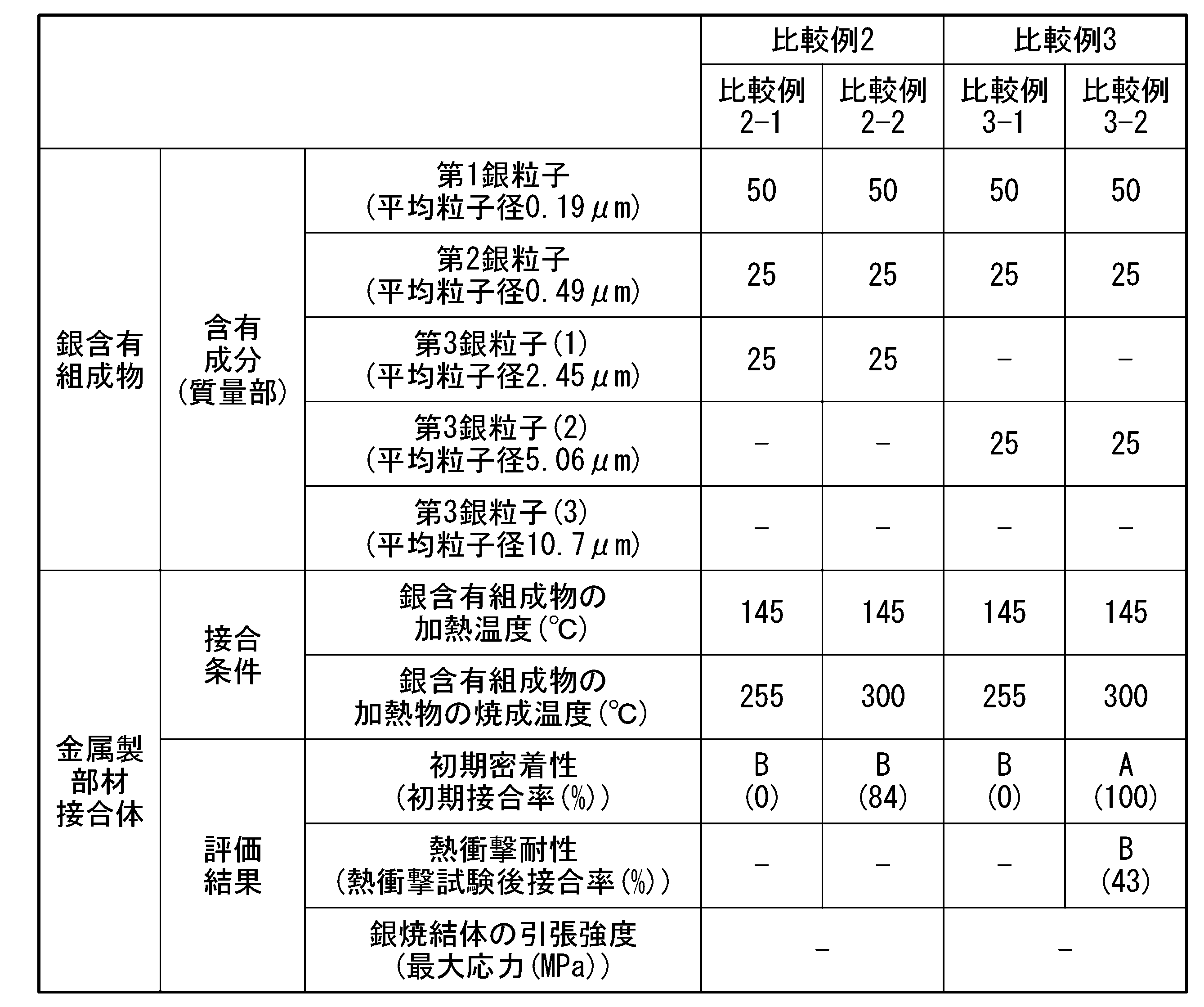
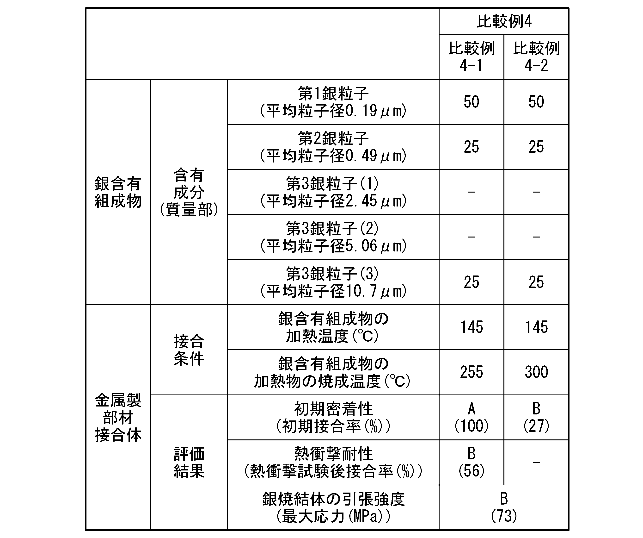
上記結果から明らかなように、実施例1においては、引張強度が高い銀焼結体を形成でき、さらに、銀含有組成物の加熱物の焼成温度が255℃及び300℃のいずれであっても(実施例1-1及び実施例1-2のいずれの場合も)、金属製部材接合体の初期密着性及び熱衝撃耐性が高かった。すなわち、幅広い温度域での焼成によって、熱衝撃耐性が高い金属製部材接合体が得られた。
実施例1の銀含有組成物は、第1銀粒子及び第2銀粒子を含有し、第3銀粒子を含有しておらず、銀含有組成物において、すべての銀粒子の合計含有量に対する、第1銀粒子及び第2銀粒子の合計含有量の割合が、100質量%であった。
実施例1の銀含有組成物は、第1銀粒子及び第2銀粒子を含有し、第3銀粒子を含有しておらず、銀含有組成物において、すべての銀粒子の合計含有量に対する、第1銀粒子及び第2銀粒子の合計含有量の割合が、100質量%であった。
これに対して、比較例1においては、銀含有組成物の加熱物の焼成温度が300℃のとき(比較例1-2の場合)に、金属製部材接合体の初期密着性が低かった。そのため、前記焼成温度が300℃のときには、金属製部材接合体の熱衝撃耐性を評価しなかった。比較例1の銀含有組成物は、幅広い温度域での焼成によって、熱衝撃耐性が高い金属製部材接合体が得られるものではなかった。
比較例1の銀含有組成物は、第1銀粒子を含有していたが、第2銀粒子を含有していなかった。
比較例1の銀含有組成物は、第1銀粒子を含有していたが、第2銀粒子を含有していなかった。
比較例2においては、銀含有組成物の加熱物の焼成温度が255℃及び300℃のいずれであっても(比較例2-1及び比較例2-2のいずれの場合も)、金属製部材接合体の初期密着性が低かった。そのため、前記焼成温度が255℃及び300℃のいずれのときも、金属製部材接合体の熱衝撃耐性を評価しなかった。比較例2の銀含有組成物は、幅広い温度域での焼成によって、熱衝撃耐性が高い金属製部材接合体が得られるものではなかった。
比較例2の銀含有組成物は、第1銀粒子、第2銀粒子及び第3銀粒子を含有しており、銀含有組成物において、すべての銀粒子の合計含有量に対する、第1銀粒子及び第2銀粒子の合計含有量の割合が、75質量%であった。
比較例2の銀含有組成物は、第1銀粒子、第2銀粒子及び第3銀粒子を含有しており、銀含有組成物において、すべての銀粒子の合計含有量に対する、第1銀粒子及び第2銀粒子の合計含有量の割合が、75質量%であった。
比較例3においては、銀含有組成物の加熱物の焼成温度が255℃のとき(比較例3-1の場合)に、金属製部材接合体の初期密着性が低かった。そのため、前記焼成温度が255℃のときには、金属製部材接合体の熱衝撃耐性を評価しなかった。さらに、銀含有組成物の加熱物の焼成温度が300℃のとき(比較例3-2の場合)に、金属製部材接合体の熱衝撃耐性が低かった。比較例3の銀含有組成物は、幅広い温度域での焼成によって、熱衝撃耐性が高い金属製部材接合体が得られるものではなかった。
比較例3の銀含有組成物は、第1銀粒子、第2銀粒子及び第3銀粒子を含有しており、銀含有組成物において、すべての銀粒子の合計含有量に対する、第1銀粒子及び第2銀粒子の合計含有量の割合が、75質量%であった。
比較例3の銀含有組成物は、第1銀粒子、第2銀粒子及び第3銀粒子を含有しており、銀含有組成物において、すべての銀粒子の合計含有量に対する、第1銀粒子及び第2銀粒子の合計含有量の割合が、75質量%であった。
比較例4においては、銀含有組成物の加熱物の焼成温度が255℃のとき(比較例4-1の場合)に、金属製部材接合体の熱衝撃耐性が低かった。さらに、前記焼成温度が300℃のとき(比較例4-2の場合)に、金属製部材接合体の初期密着性が低かった。そのため、前記焼成温度が300℃のときには、金属製部材接合体の熱衝撃耐性を評価しなかった。比較例4の銀含有組成物は、幅広い温度域での焼成によって、熱衝撃耐性が高い金属製部材接合体が得られるものではなかった。さらに、比較例4においては、引張強度が高い銀焼結体を形成できなかった。
比較例4の銀含有組成物は、第1銀粒子、第2銀粒子及び第3銀粒子を含有しており、銀含有組成物において、すべての銀粒子の合計含有量に対する、第1銀粒子及び第2銀粒子の合計含有量の割合が、75質量%であった。
比較例4の銀含有組成物は、第1銀粒子、第2銀粒子及び第3銀粒子を含有しており、銀含有組成物において、すべての銀粒子の合計含有量に対する、第1銀粒子及び第2銀粒子の合計含有量の割合が、75質量%であった。
比較例2~4の結果から、銀含有組成物が第3銀粒子を含有している場合、第3銀粒子の平均粒子径が大きくなると、金属製部材接合体の初期密着性が改善する傾向が見られた。しかし、銀含有組成物の加熱物の焼成温度が255℃及び300℃の両方の場合で、金属製部材接合体の熱衝撃耐性が改善するには至らなかった。
本発明は、回路基板をはじめとする、金属製部材接合体を備えた各種装置の製造に利用可能である。
1・・・金属製部材接合体、11・・・金属製の第1部材、12・・・金属製の第2部材、13・・・銀焼結体、130・・・銀含有組成物、130’・・・銀含有組成物の加熱物
Claims (5)
- 銀含有組成物であって、
前記銀含有組成物は、平均粒子径が0.1μm以上0.4μm未満の第1銀粒子と、平均粒子径が0.4μm以上2.3μm未満の第2銀粒子と、を含有し、
前記銀含有組成物において、すべての銀粒子の合計含有量に対する、前記第1銀粒子及び第2銀粒子の合計含有量の割合が、80質量%以上である、銀含有組成物。 - 前記銀含有組成物において、すべての銀粒子の合計含有量に対する、前記第1銀粒子の含有量の割合が、55質量%以上である、請求項1に記載の銀含有組成物。
- 前記銀含有組成物において、すべての銀粒子の合計含有量に対する、前記第2銀粒子の含有量の割合が、10質量%以上である、請求項1又は2に記載の銀含有組成物。
- 前記銀含有組成物において、すべての銀粒子の合計含有量に対する、平均粒子径が0.1μm未満の銀粒子の含有量の割合が、10質量%以下である、請求項1又は2に記載の銀含有組成物。
- 銀焼結体であって、
前記銀焼結体は、平均粒子径が0.1μm以上0.4μm未満の第1銀粒子と、平均粒子径が0.4μm以上2.3μm未満の第2銀粒子と、を含有する銀含有組成物を用いて形成され、
前記銀焼結体と同じ組成の試験片として、その幅が5mmであり、測定対象部位の長さが6mmであり、厚さが0.1mmである試験片を作製し、前記試験片をその長さ方向において、試験速度1×10⁻⁴/sで引っ張る引張試験を行ったとき、前記試験片の最大応力が、100MPa以上である、銀焼結体。
Applications Claiming Priority (2)
| Application Number | Priority Date | Filing Date | Title |
|---|---|---|---|
| JP2022124013A JP2024021289A (ja) | 2022-08-03 | 2022-08-03 | 銀含有組成物及び銀焼結体 |
| JP2022-124013 | 2022-08-03 |
Publications (1)
| Publication Number | Publication Date |
|---|---|
| WO2024029487A1 true WO2024029487A1 (ja) | 2024-02-08 |
Family
ID=89849324
Family Applications (1)
| Application Number | Title | Priority Date | Filing Date |
|---|---|---|---|
| PCT/JP2023/027942 Ceased WO2024029487A1 (ja) | 2022-08-03 | 2023-07-31 | 銀含有組成物及び銀焼結体 |
Country Status (2)
| Country | Link |
|---|---|
| JP (1) | JP2024021289A (ja) |
| WO (1) | WO2024029487A1 (ja) |
Cited By (1)
| Publication number | Priority date | Publication date | Assignee | Title |
|---|---|---|---|---|
| CN121463573A (zh) * | 2025-12-30 | 2026-02-03 | 晶科能源(海宁)有限公司 | 光伏电池及其制造方法、叠层电池及光伏组件 |
Families Citing this family (1)
| Publication number | Priority date | Publication date | Assignee | Title |
|---|---|---|---|---|
| WO2025196955A1 (ja) * | 2024-03-19 | 2025-09-25 | 株式会社タムラ製作所 | 接合材 |
Citations (3)
| Publication number | Priority date | Publication date | Assignee | Title |
|---|---|---|---|---|
| WO2021044817A1 (ja) * | 2019-09-02 | 2021-03-11 | 株式会社大阪ソーダ | 銀粒子 |
| JP2021059769A (ja) * | 2019-10-09 | 2021-04-15 | 東洋アルミニウム株式会社 | 複合粒子、複合粒子の製造方法、および複合粒子を含むインク |
| JP2021195592A (ja) * | 2020-06-15 | 2021-12-27 | Jsr株式会社 | 組成物、銀焼結物の形成方法、接合方法、物品及び物品の製造方法 |
Family Cites Families (2)
| Publication number | Priority date | Publication date | Assignee | Title |
|---|---|---|---|---|
| JP4212035B2 (ja) * | 2003-06-05 | 2009-01-21 | 株式会社ノリタケカンパニーリミテド | 銀粉末を主体とする導体ペースト及びその製造方法 |
| JP6975527B2 (ja) * | 2015-11-30 | 2021-12-01 | Dowaエレクトロニクス株式会社 | 球状銀粉およびその製造方法、ならびに導電性ペースト |
-
2022
- 2022-08-03 JP JP2022124013A patent/JP2024021289A/ja active Pending
-
2023
- 2023-07-31 WO PCT/JP2023/027942 patent/WO2024029487A1/ja not_active Ceased
Patent Citations (3)
| Publication number | Priority date | Publication date | Assignee | Title |
|---|---|---|---|---|
| WO2021044817A1 (ja) * | 2019-09-02 | 2021-03-11 | 株式会社大阪ソーダ | 銀粒子 |
| JP2021059769A (ja) * | 2019-10-09 | 2021-04-15 | 東洋アルミニウム株式会社 | 複合粒子、複合粒子の製造方法、および複合粒子を含むインク |
| JP2021195592A (ja) * | 2020-06-15 | 2021-12-27 | Jsr株式会社 | 組成物、銀焼結物の形成方法、接合方法、物品及び物品の製造方法 |
Cited By (1)
| Publication number | Priority date | Publication date | Assignee | Title |
|---|---|---|---|---|
| CN121463573A (zh) * | 2025-12-30 | 2026-02-03 | 晶科能源(海宁)有限公司 | 光伏电池及其制造方法、叠层电池及光伏组件 |
Also Published As
| Publication number | Publication date |
|---|---|
| JP2024021289A (ja) | 2024-02-16 |
Similar Documents
| Publication | Publication Date | Title |
|---|---|---|
| JP5830302B2 (ja) | 加熱接合用材料、加熱接合用シート体、及び加熱接合用成形体 | |
| EP2455179B1 (en) | Bonding material and bonding method each using metal nanoparticles | |
| TWI636842B (zh) | 接合材及使用其之接合方法 | |
| US12048964B2 (en) | Bonding material and bonding method using same | |
| TWI892998B (zh) | 低溫燒結性接合用膏、低溫燒結性接合用膏製造用材料及其製造方法、以及接合結構體 | |
| TWI668065B (zh) | Solder powder, method for producing same, and method for preparing solder paste using the same | |
| WO2014129626A1 (ja) | 接続構造体、及び半導体装置 | |
| KR20180004853A (ko) | 접합재료, 접합체, 및 접합방법 | |
| JP6849374B2 (ja) | 接合用の導電性ペースト | |
| JP2024021289A (ja) | 銀含有組成物及び銀焼結体 | |
| JP7164775B2 (ja) | 接合用導電性ペースト | |
| US20200035637A1 (en) | Bonding material and bonded product using same | |
| US10821558B2 (en) | Bonding material and bonding method using same | |
| JP5923698B2 (ja) | 貴金属ペーストを用いた半導体デバイスの製造方法 | |
| JP7082231B2 (ja) | 導電性組成物、導電性焼結部、および導電性焼結部を備えている部材 | |
| JP2019067514A (ja) | 導体形成用組成物、並びに接合体及びその製造方法 | |
| JP7155654B2 (ja) | 接合体の製造方法 | |
| JP2024021288A (ja) | 金属製部材の接合方法及び銀焼結体 | |
| JP2022003161A (ja) | 接合材、接合材の製造方法及び接合方法 | |
| CN116837265A (zh) | 一种液态金属导热材料及其涂层与制备方法和应用 | |
| JP7487011B2 (ja) | 接合材、接合材の製造方法及び接合方法 | |
| JP7093945B2 (ja) | ナノ銀ペーストを用いた半導体チップ接合方法 | |
| JP2021138991A (ja) | 接合材、接合材の製造方法及び接合方法 | |
| EP3189914A1 (en) | Bonding material and bonding method using same | |
| JP2016087606A (ja) | Au−Sn合金はんだペースト、Au−Sn合金はんだペーストの製造方法、Au−Sn合金はんだ層の製造方法、及びAu−Sn合金はんだ層 |
Legal Events
| Date | Code | Title | Description |
|---|---|---|---|
| 121 | Ep: the epo has been informed by wipo that ep was designated in this application |
Ref document number: 23850042 Country of ref document: EP Kind code of ref document: A1 |
|
| NENP | Non-entry into the national phase |
Ref country code: DE |
|
| 122 | Ep: pct application non-entry in european phase |
Ref document number: 23850042 Country of ref document: EP Kind code of ref document: A1 |