WO2024028942A1 - 光クロスコネクト装置及びその製造方法 - Google Patents
光クロスコネクト装置及びその製造方法 Download PDFInfo
- Publication number
- WO2024028942A1 WO2024028942A1 PCT/JP2022/029474 JP2022029474W WO2024028942A1 WO 2024028942 A1 WO2024028942 A1 WO 2024028942A1 JP 2022029474 W JP2022029474 W JP 2022029474W WO 2024028942 A1 WO2024028942 A1 WO 2024028942A1
- Authority
- WO
- WIPO (PCT)
- Prior art keywords
- optical
- core
- route
- connect device
- fiber
- Prior art date
- Legal status (The legal status is an assumption and is not a legal conclusion. Google has not performed a legal analysis and makes no representation as to the accuracy of the status listed.)
- Ceased
Links
Images



Classifications
-
- G—PHYSICS
- G02—OPTICS
- G02B—OPTICAL ELEMENTS, SYSTEMS OR APPARATUS
- G02B6/00—Light guides; Structural details of arrangements comprising light guides and other optical elements, e.g. couplings
- G02B6/24—Coupling light guides
- G02B6/26—Optical coupling means
- G02B6/35—Optical coupling means having switching means
Definitions
- the present invention relates to an optical cross-connect device and a manufacturing method thereof.
- a multistage loop network configuration has been proposed as one form of optical access network configuration (see Non-Patent Document 1).
- a multi-stage loop network configuration since the optical access network is configured with a plurality of loops, there is an advantage that redundant paths can be easily secured.
- a fiber switching function that switches the optical fiber route at the point where multiple loops meet in the multi-stage loop network. has been done.
- the fiber switching function can be realized by an optical cross-connect device that switches the signal path.
- an optical cross-connect device that switches the signal path.
- a configuration in which multiple optical switches that can mechanically switch optical paths without converting optical signals to electrical signals are used, and the optical switches are connected using optical fibers. has been proposed (see Non-Patent Document 2).
- the fiber switching function needs to be able to mutually switch the connections of the optical fiber cores of a plurality of routes for routes having one or more optical fiber cores.
- the number of optical fibers connected to optical cross-connect devices increases from each route, the number of optical fibers connecting between optical switches increases, and the number of optical switches connected to each optical fiber of each optical switch increases. Because of the differences, the work involved in wiring optical fibers during manufacturing and maintenance was heavy.
- the present invention is proposed in view of the above circumstances, and is capable of mutually switching the connections of the optical fibers of a plurality of routes for routes having one or more coated optical fibers, It is an object of the present invention to provide an optical cross-connect device and a method for manufacturing the same that can reduce the burden of optical fiber wiring.
- an optical cross-connect device connects optical fibers between a plurality of routes having one or more coated optical fibers.
- An optical cross-connect device for switching which includes an optical switch that connects to each optical fiber on the input side, a multi-fiber optical connector that connects on the input side to the output side of each optical switch via parallel optical fibers, and For multi-fiber optical connectors that are connected to optical fibers in one route via an optical switch, the connection between the output side of the multi-fiber optical connector in one route and the output side of the multi-core optical connector in the other route is The optical switch connects one of the optical fibers in the path to one of the optical paths.
- the method for manufacturing an optical cross-connect device includes a step of connecting an optical switch to one piece of a multi-fiber optical connector, a step of manufacturing a portion from an optical wiring path to another piece of the multi-fiber optical connector, and The method may also include a step of connecting one piece of the fiber optic connector to the other piece.
- the present invention for a route having one or more coated optical fibers, it is possible to reduce the burden of wiring optical fibers that can mutually switch the connections of the coated optical fibers of a plurality of routes.
- FIG. 1 is a diagram showing an optical cross-connect device according to a first embodiment
- FIG. FIG. 3 is a diagram showing the appearance of the optical wiring path according to the first embodiment. It is a schematic diagram explaining operation of an optical switch.
- FIG. 3 is a schematic diagram illustrating the operation of the optical cross-connect device.
- FIG. 7 is a diagram showing an optical cross-connect device according to a second embodiment.
- FIG. 7 is a diagram showing an optical cross-connect device according to a third embodiment.
- the optical connector device of this embodiment can mutually switch optical fibers in four directions for a route having two optical fibers at a point where two loops touch in a multi-stage loop network configuration. It is assumed that However, the present invention is not limited to this, and can be applied to an optical cross-connect device that can mutually switch optical fibers of a plurality of routes, for routes having one or more optical fibers.
- FIG. 1 is a diagram showing the configuration of an optical cross-connect device according to a first embodiment.
- each of the four routes D1 to D4 has two optical fibers 10 1 to 10 8 , and the optical fibers 10 1 to 10 8 are It is connected to the input side of optical switches 20 1 to 20 8 provided on each optical fiber core 10 1 to 10 8 .
- NxM optical switches can be provided on NxM optical fibers.
- the output sides of the optical switches 20 1 to 20 8 are connected to the input sides of multi-core optical connectors 30 1 to 30 8 , respectively, by optical fiber groups 11 1 to 11 8 , respectively.
- Each of the optical fiber groups 11 1 to 11 8 is composed of six parallel optical fibers.
- the multi-fiber optical connectors 30 1 to 30 8 are composed of one piece on the input side and the other piece on the output side, and by mechanically connecting or disconnecting one piece and the other piece, the optical fiber group 11 on the input side can be connected.
- the optical path between the optical fibers 1 to 118 and the output side optical fiber group 12 can be connected or disconnected.
- the optical fiber group 12 is composed of six parallel optical fibers.
- the multi-core optical connectors 30 1 to 30 8 of this embodiment use MT connectors, which are also referred to as F12 type multi-core optical fiber connectors.
- the optical fiber to be attached to the MT connector is adhesively fixed to the optical fiber insertion hole of the MT ferrule, and the connecting end surface of the core wire is polished at a right angle.
- the optical fibers may be provided in pigtails from optical switches 20 1 - 20 8 or the like.
- the MT connector is filled with a refractive index matching agent between the end faces, and is connected by inserting the guide pin attached to one MT ferrule into the guide pin hole of the other MT ferrule and fitting the MT ferrules together. There is.
- MPO connectors also called F13 type multi-fiber optical fiber connectors
- F13 type multi-fiber optical fiber connectors may be used for the multi-fiber optical connectors 30 1 to 30 8 instead of the MT connectors.
- the MT ferrule end face is polished obliquely, the MT ferrule is built into the MPO plug housing, and the MPO plug is connected within the MPO adapter.
- output sides of multi-fiber optical connectors 30 1 to 30 8 connected to optical fibers 10 1 to 10 8 of routes D1 to D4 via optical switches 20 1 to 20 8 , and others are connected to the output sides of the multi-core optical connectors 30 1 to 30 8 by optical fiber groups 12, respectively.
- the output side of the multi-core optical connector 30 1 connected to the optical fiber core 10 1 of the route D 1 via the optical switch 20 1 is It is connected to the output sides of other multi-core optical connectors 30 3 to 30 8 via optical fiber groups 12, respectively.
- the output side of the multi-core optical connector 30 2 connected to the optical fiber core 10 2 of the route D1 via the optical switch 20 2 is connected to a cable other than the multi-core optical connectors 30 1 and 30 2 It is connected to the output sides of other multi-core optical connectors 30 3 to 30 8 via optical fiber groups 12, respectively.
- the optical fiber group 12 connecting the output sides of the multi-core optical connectors 30 1 to 30 8 constitutes an optical wiring path 40 .
- the optical fiber group 12 includes optical fiber core wires 10 1 to 10 8 of routes D1 to D4 and optical switches 20 1 to 20 8 .
- Single-mode optical fibers are used that have lower bending loss than the optical fiber groups 11 1 to 11 8 that connect the fiber optics and the multi-core optical connectors 30 1 to 30 8 .
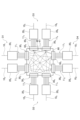
- FIG. 2 is a diagram showing the appearance of the optical wiring path 40 of the first embodiment.
- FIG. 2 shows an example of the mode of the optical wiring path 40 configured by the optical fiber group 12 on the board 50, and the optical fiber group 12 is connected to the optical wiring path 40 shown in FIG. It is not a reflection.
- the optical wiring path 40 is supported along the surface of the substrate 50 except for the ends of the optical fiber group 12 connected to the multi-core optical connectors 30 1 to 30 4 .
- the optical wiring path 40 is constructed by wiring the optical fiber group 12 on an adhesive sheet attached to a sheet-like substrate 50 made of a resin such as polyimide, and sandwiching the optical fiber group 12 between polyimide sheets with an adhesive sheet attached thereto. There is.
- the optical fiber group 12 may be embedded in a sheet-like substrate 50 made of resin such as polyimide.
- the substrate 50 is flexible together with the optical wiring path 40 to which it is fixed.
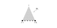
- FIG. 3 is a schematic diagram illustrating the operation of the optical switches 20 1 to 20 8 .
- the optical switch 20 1 connected to the optical fiber core 10 1 of the first route will be explained as an example.
- the optical switch 201 constitutes a 1 ⁇ 6 optical switch having one port on the input side and six ports on the output side.
- the optical fiber core 101 of the route D1 is connected to the input port 1
- the optical fibers connected to the multi-core optical connectors 303 to 308 are connected to the output ports 1-1 to 1-6.
- Six optical fibers forming group 111 are connected to each other.
- the number of routes is N and the number of optical fibers in each route is M
- the optical switch 201 switches and connects the optical path between the input port 1 and any one of the output ports 1-1 to 1-6. That is, the optical fiber core wire 10 1 is connected to any one of the six optical fibers constituting the optical fiber group 11 1 .
- Such switching of the optical paths may be realized by mechanically butting or separating the optical paths without converting the optical signals into electrical signals. Further, such connection control may be based on a control signal.
- the optical switch 20 1 has been described here, the same applies to the other optical switches 20 2 to 20 8 .
- FIG. 4 is a schematic diagram illustrating the operation of the optical cross-connect device.
- FIG . 4 corresponds to the optical cross -connect device shown in FIG. 1 to 11 8 and multi-core optical connectors 30 1 to 30 8 are omitted.
- the optical fibers 10 1 and 10 2 of the path D1 are connected to the input ports 1 and 2 of the optical switches 20 1 and 20 2, respectively.
- the output ports 1-1 to 1-6 and 2-1 to 2-6 of the optical switches 20 1 and 20 2 are connected to other optical switches 20 through optical paths including the optical fiber group 12 constituting the optical wiring path 40. Connected to one of the 3 to 20 8 output ports. The same applies to the other optical switches 20 3 to 20 8 .
- this optical cross-connect device as a first connection mode, it is possible to connect between the route D1 and the route D2, and between the route D3 and the route D4. At this time, between the route D1 and the route D2, the optical switches 20 1 and 20 2 corresponding to the route D1 and the optical switches 20 3 and 20 4 corresponding to the route D2 are connected through the optical wiring route 40. connected to each other. Therefore, the optical fibers 10 1 and 10 2 in the route D1 and the optical fibers 10 3 and 10 4 in the route D2 are connected to each other.
- the optical fiber coated wire 101 of the first route D1, the optical fiber coated wire 103 of the second route D2, the optical fiber coated wire 102 of the first route D1, and the light of the second route D2 The fiber coated wire 104 may be connected, or conversely, the optical fiber coated wire 101 of the first route D1 and the optical fiber coated wire 104 of the second route D2 may be connected.
- the optical fiber coated wire 102 and the optical fiber coated wire 103 of the second route D2 may be connected.
- the optical switches 20 5 and 20 6 corresponding to the route D3 and the optical switches 20 7 and 20 8 corresponding to the route D4 are connected, and the optical fiber core of the route D3 is connected.
- the wires 10 5 and 10 6 and the optical fiber core wires 10 7 and 10 8 of the route D4 are connected to each other.
- the fiber coated wire 108 may be connected, or conversely, the optical fiber coated wire 105 of the third route D3 and the optical fiber coated wire 108 of the fourth route D4 may be connected.
- the optical fiber coated wire 106 and the optical fiber coated wire 107 of the fourth route D3 may be connected.
- the optical cross-connect device as a second connection mode, it is possible to connect between the route D1 and the route D3, and between the route D2 and the route D4. Furthermore, as a third connection mode, the route D1 and the route D4 can be connected, and the route D2 and the route D3 can be connected, respectively.
- the optical switches 20 1 to 20 8 corresponding to the connecting routes D1 to D4 are appropriately connected via the optical wiring path 40.
- the optical fibers 10 1 to 10 9 of the routes D1 to D4 are appropriately connected.
- the optical cross-connect device having the above-mentioned configuration includes a process for manufacturing a part of the optical cross-connect device from the optical switches 20 1 to 20 8 to one piece of the multi-core optical connectors 30 1 to 30 8 , and , a process of manufacturing a part from the optical wiring path 40 to the other pieces of the multi-fiber optical connectors 30 1 to 30 8 , and a process of connecting one piece of the multi-fiber optical connectors 30 1 to 30 8 and the other pieces. I can do it.
- the optical switches 20 1 - 20 8 are connected to one piece of the multi-core optical connectors 30 1 - 30 8 via optical fiber groups 11 1 - 11 8 .
- An optical wiring path 40 is configured by appropriately arranging the optical fiber group 12 on the substrate 50, and the optical wiring path 40 is connected to the other pieces of the multi-core optical connectors 30 1 to 30 8 .
- one piece of the multi-core optical connectors 30 1 to 30 8 is connected to the other piece.
- the optical wiring path 40 is attached to the optical switches 20 1 to 20 8 by the multi-core optical connectors 30 1 to 30 8 so as to be connectable and detachable. It is being Therefore, the optical wiring between the optical wiring path 40 and the optical switches 20 1 to 20 8 is completed simply by connecting the multi-core optical connectors 30 1 to 30 8 , making it easy to manufacture the optical cross-connect device. . It is no longer necessary to carry out complicated wiring of the optical fiber group 12 such as connecting the optical fiber group 12 for each single fiber or wiring the optical fiber group 12 in a crossing manner, and it is possible to manufacture an optical cross-connect device. The burden of work will be reduced.
- optical fibers are pulled out from optical switch housings to form pigtails, and the optical fibers are connected to each other to provide optical wiring between optical switches.
- fusion splicing optical fibers destined for different destinations, it is necessary to provide extra length for the optical fibers to be connected by the equipment that performs the fusion splicing.
- the work of accommodating the excess length of optical fibers has hindered the improvement of the assembly workability of optical cross-connect devices.
- the optical wiring path 40 can be connected and removed by the multi-core optical connectors 30 1 to 30 8 . There is no need to fusion splice each single fiber or provide extra length for the optical fiber, reducing the manufacturing burden.
- the optical wiring path 40 can be downsized.
- single-mode optical fibers with low optical fiber bending loss for the optical fiber group 12 of the optical wiring path 40 it becomes possible to bend the optical fibers with a small radius of curvature, and the optical wiring path 40 can be further miniaturized. I can do it. Since the optical cross-connect device in a multi-stage loop network is installed in an outdoor closure, its miniaturization allows it to be installed in a closure with limited space.
- the optical wiring path 40 can be removed using the multi-core optical connectors 30 1 to 30 8 , which improves the maintainability of the optical cross-connect device.
- the optical fiber groups 12 are wired to the optical switches 20 1 to 20 8 by fusion splicing, each optical fiber group 12 of the optical switches 20 1 to 20 8 that has failed is found and fused one by one.
- work such as cutting off the connected parts is required, in this embodiment, the optical switches 20 1 to 20 8 and the optical fiber group 12 can be removed using the multi-core optical connectors 30 1 to 30, so the work is not necessary. The burden of this will be reduced.
- FIG. 5 is a diagram showing the configuration of an optical cross-connect device according to the second embodiment.
- the optical cross-connect device of the second embodiment differs from the optical cross-connect device of the first embodiment in that most of the optical wiring path 40 is constituted by an optical waveguide. Since the other configurations are the same as those of the optical cross-connect device of the first embodiment, corresponding components will be referred to with common reference numerals.
- each of the four routes D1 to D4 has two optical fibers 10 1 to 10 8 , and the optical fibers 10 1 to 10 8 are It is connected to the input side of optical switches 20 1 to 20 8 provided on each optical fiber core 10 1 to 10 8 .
- the output sides of the optical switches 20 1 to 20 8 are respectively connected to the input sides of multi-core optical connectors 30 1 to 30 8 by optical fiber groups 11 1 to 11 8 each composed of six parallel optical fibers.
- the multi-fiber optical connectors 30 1 to 30 8 are composed of one piece on the input side and the other piece on the output side, and by mechanically connecting or disconnecting one piece and the other piece, the optical fiber group 11 on the input side is connected.
- the optical path can be connected or disconnected between the optical fibers 1 to 118 and the group of six optical fibers 12 on the output side.
- MPO connectors may also be used.
- optical waveguide 61 may be formed on the surface of the substrate 60.
- the substrate 60 may be made of, for example, a crystalline substrate such as silicon dioxide.
- the optical fiber groups 13 1 to 13 8 are composed of six parallel optical fibers, similar to the optical fiber groups 11 1 to 11 8 connected to the input sides of the multi-core optical connectors 30 1 to 30 8 .
- the output sides of the optical connectors 30 1 to 30 8 are connected to an optical waveguide 61 formed on the substrate 60.
- the operation of the optical cross-connect device is similar to that of the optical cross-connect device of the first embodiment. That is, as the first connection mode, it is possible to connect between the route D1 and the route D2, and between the route D3 and the route D4. Further, as a second connection mode, it is possible to connect between the route D1 and the route D3, and between the route D2 and the route D4, and as a third connection mode, the route D1 and the route D4 can be connected. It is possible to connect between the route D2 and the route D3.
- the optical switches 20 1 to 20 8 corresponding to the routes D1 to D4 correspond to the routes D1 to D4 connected via the optical fiber cores 10 1 to 10 9 .
- the optical switches 20 1 to 20 8 are suitably connected to the optical switches 20 1 to 20 8 . Therefore, the optical fibers 10 1 to 10 8 of the routes D1 to D4 are appropriately connected to the optical fibers 10 1 to 10 8 of the routes D1 to D4.
- the optical cross-connect device having the above-mentioned configuration includes a process for manufacturing a part of the optical cross-connect device from the optical switches 20 1 to 20 8 to one piece of the multi-core optical connectors 30 1 to 30 8 , and , a process of manufacturing a part from the optical wiring path 40 to the other pieces of the multi-fiber optical connectors 30 1 to 30 8 , and a process of connecting one piece of the multi-fiber optical connectors 30 1 to 30 8 and the other pieces. I can do it.
- the optical switches 20 1 to 20 8 are connected to one piece of the multi-core optical connectors 30 1 to 30 8 via the optical fiber groups 11 1 to 11 8 , and the optical waveguide 61 formed on the substrate 60 is connected to the optical fiber groups 11 1 to 11 8. It is connected to the other pieces of the multi-core optical connectors 30 1 to 30 8 via 13 1 to 13 8 . Then, one piece of the multi-core optical connectors 30 1 to 30 8 is connected to the other piece.
- the optical wiring path 40 is constituted by an optical waveguide formed on the substrate 60. Since the optical waveguide allows high-density wiring, the optical wiring path 40 can be miniaturized. Furthermore, since the optical waveguide is formed integrally with the substrate 60, it is robust.
- the optical wiring path 40 is connected to the optical switches 20 1 to 20 8 and the multi-core optical connectors 30 1 to 30 8. It is attached so that it can be connected and removed. Therefore, by simply connecting the optical wiring path 40 to the multi-core optical connectors 30 1 to 30 8 , the optical wiring between the optical wiring path 40 and the optical switches 20 1 to 20 8 is completed, and an optical cross-connect device is manufactured. This reduces the burden of work required to do so.
- the optical wiring path 40 can be downsized, even when space is limited such as in an outdoor closure. It can be installed due to its miniaturization. Furthermore, even when a failure occurs in the optical cross-connect device, the optical wiring path 40 can be removed simply by disconnecting the multi-core optical connectors 30 1 to 30 8 , thereby improving the maintainability of the optical cross-connect device.
- FIG. 6 is a diagram showing the configuration of an optical cross-connect device according to the third embodiment.
- the entire optical wiring path 40 is composed of optical waveguides, and the output sides of the multi-core optical connectors 30 1 to 30 8 are connected to the periphery of the substrate 60 on which the optical waveguides are formed.
- This is different from the optical cross-connect device of the first embodiment in that it is attached. Since the other configurations are the same as those of the optical cross-connect device of the first embodiment, corresponding components will be referred to with common reference numerals.
- each of the four routes D1 to D4 has two optical fibers 10 1 to 10 8 , and the optical fibers 10 1 to 10 8 are It is connected to the input side of optical switches 20 1 to 20 8 provided on each optical fiber core 10 1 to 10 8 .
- the output sides of the optical switches 20 1 to 20 8 are respectively connected to the input sides of multi-core optical connectors 30 1 to 30 8 by optical fiber groups 11 1 to 11 8 each composed of six parallel optical fibers.
- the multi-fiber optical connectors 30 1 to 30 8 are composed of one piece on the input side and the other piece on the output side, and by mechanically connecting or disconnecting one piece and the other piece, the optical fiber group 11 1 on the input side is connected. 118 and the six optical fiber groups 12 connected to the optical wiring path 40 on the output side.
- MT connectors are used for the multi-core optical connectors 30 1 to 30 8
- MPO connectors may also be used.
- optical waveguide 61 may be formed on the surface of the substrate 60.
- the substrate 60 may be made of, for example, a crystalline substrate such as silicon dioxide.
- the operation of the optical cross-connect device is similar to that of the optical cross-connect device of the first embodiment. That is, as the first connection mode, the route D1 and the route D2, and the route D3 and the route D4 can be connected, respectively. Further, as a second connection mode, the route D1 and the route D3, and the route D2 and the route D4 can be connected, respectively. As a third connection mode, the route D1 and the route D4, the route D2 and the route D4 can be connected, respectively. The paths D3 can be connected respectively.
- the optical switches 20 1 to 20 8 corresponding to the routes D1 to D4 correspond to the routes D1 to D4 connected via the optical fiber cores 10 1 to 10 8 .
- the optical switches 20 1 to 20 8 are suitably connected to the optical switches 20 1 to 20 8 . Therefore, the optical fibers 10 1 to 10 8 of the routes D1 to D4 are appropriately connected to the optical fibers 10 1 to 10 8 of the routes D1 to D4.
- the optical cross-connect device having the above-mentioned configuration includes a process for manufacturing a part of the optical cross-connect device from the optical switches 20 1 to 20 8 to one piece of the multi-core optical connectors 30 1 to 30 8 , and , a process of manufacturing a part from the optical wiring path 40 to the other pieces of the multi-fiber optical connectors 30 1 to 30 8 , and a process of connecting one piece of the multi-fiber optical connectors 30 1 to 30 8 and the other pieces. I can do it.
- the optical switches 20 1 to 20 8 are connected to one piece of the multi-core optical connectors 30 1 to 30 8 via the optical fiber groups 11 1 to 11 8 , and the optical waveguide 61 formed on the substrate 60 is It is connected to the other pieces of the connectors 30 1 to 30 8 . Then, one piece of the multi-core optical connectors 30 1 to 30 8 is connected to the other piece.
- the entire optical wiring path 40 is constituted by an optical waveguide formed on a substrate 60.
- the optical waveguide allows for high-density wiring, and since the entire optical wiring path 40 is formed of the optical waveguide, further miniaturization of the optical wiring path 40 is possible.
- the optical waveguide is formed integrally with the substrate 60, and the output sides of the multi-core optical connectors 30 1 to 30 8 are also attached to the periphery of the substrate 60 and are directly connected to the optical waveguide formed on the substrate 60. It is robust.
- the optical wiring path 40 is connected to the optical switches 20 1 to 20 8 and the multi-core optical connectors 30 1 to 30 8. It is attached so that it can be connected and removed. Therefore, optical wiring between the optical wiring path 40 and the optical switches 20 1 to 20 8 is completed simply by connecting the optical wiring path 40 to the multi-core optical connectors 30 1 to 30 8 , and an optical cross-connect device is manufactured. This reduces the burden of work required to do so.
- the optical wiring path 40 can be made smaller, and even when space is limited such as in an outdoor closure. It can be installed due to its miniaturization. Furthermore, even when a failure occurs in the optical cross-connect device, the optical wiring path 40 can be removed using the multi-core optical connectors 30 1 to 30 8 , which improves the maintainability of the optical cross-connect device.
Landscapes
- Physics & Mathematics (AREA)
- General Physics & Mathematics (AREA)
- Optics & Photonics (AREA)
- Optical Communication System (AREA)
Priority Applications (2)
| Application Number | Priority Date | Filing Date | Title |
|---|---|---|---|
| PCT/JP2022/029474 WO2024028942A1 (ja) | 2022-08-01 | 2022-08-01 | 光クロスコネクト装置及びその製造方法 |
| JP2024538537A JP7828018B2 (ja) | 2022-08-01 | 2022-08-01 | 光クロスコネクト装置及びその製造方法 |
Applications Claiming Priority (1)
| Application Number | Priority Date | Filing Date | Title |
|---|---|---|---|
| PCT/JP2022/029474 WO2024028942A1 (ja) | 2022-08-01 | 2022-08-01 | 光クロスコネクト装置及びその製造方法 |
Publications (1)
| Publication Number | Publication Date |
|---|---|
| WO2024028942A1 true WO2024028942A1 (ja) | 2024-02-08 |
Family
ID=89848685
Family Applications (1)
| Application Number | Title | Priority Date | Filing Date |
|---|---|---|---|
| PCT/JP2022/029474 Ceased WO2024028942A1 (ja) | 2022-08-01 | 2022-08-01 | 光クロスコネクト装置及びその製造方法 |
Country Status (2)
| Country | Link |
|---|---|
| JP (1) | JP7828018B2 (cg-RX-API-DMAC7.html) |
| WO (1) | WO2024028942A1 (cg-RX-API-DMAC7.html) |
Citations (4)
| Publication number | Priority date | Publication date | Assignee | Title |
|---|---|---|---|---|
| JP2002258081A (ja) * | 2001-02-28 | 2002-09-11 | Fujitsu Ltd | 光配線基板、光配線基板の製造方法及び多層光配線 |
| US20040264847A1 (en) * | 2000-08-04 | 2004-12-30 | Seungug Koh | Micro-opto-electro-mechanical waveguide switches |
| JP2015184667A (ja) * | 2014-03-26 | 2015-10-22 | インターナショナル・ビジネス・マシーンズ・コーポレーションInternational Business Machines Corporation | 光デバイス、光コネクタ・アセンブリおよび光接続方法 |
| WO2022009291A1 (ja) * | 2020-07-06 | 2022-01-13 | 日本電信電話株式会社 | 波長クロスコネクト装置及び波長クロスコネクト方法 |
Family Cites Families (4)
| Publication number | Priority date | Publication date | Assignee | Title |
|---|---|---|---|---|
| JPH0736627B2 (ja) * | 1987-08-31 | 1995-04-19 | 日本電気株式会社 | スイッチ回路網拡張方式 |
| JP2002027513A (ja) | 2000-07-10 | 2002-01-25 | Oki Electric Ind Co Ltd | 光ノード装置 |
| JP2003107277A (ja) | 2001-10-01 | 2003-04-09 | Omron Corp | 光コネクタ用光学素子 |
| JP2008257094A (ja) | 2007-04-09 | 2008-10-23 | Hitachi Cable Ltd | 光伝送モジュール及び光パッチケーブル |
-
2022
- 2022-08-01 WO PCT/JP2022/029474 patent/WO2024028942A1/ja not_active Ceased
- 2022-08-01 JP JP2024538537A patent/JP7828018B2/ja active Active
Patent Citations (4)
| Publication number | Priority date | Publication date | Assignee | Title |
|---|---|---|---|---|
| US20040264847A1 (en) * | 2000-08-04 | 2004-12-30 | Seungug Koh | Micro-opto-electro-mechanical waveguide switches |
| JP2002258081A (ja) * | 2001-02-28 | 2002-09-11 | Fujitsu Ltd | 光配線基板、光配線基板の製造方法及び多層光配線 |
| JP2015184667A (ja) * | 2014-03-26 | 2015-10-22 | インターナショナル・ビジネス・マシーンズ・コーポレーションInternational Business Machines Corporation | 光デバイス、光コネクタ・アセンブリおよび光接続方法 |
| WO2022009291A1 (ja) * | 2020-07-06 | 2022-01-13 | 日本電信電話株式会社 | 波長クロスコネクト装置及び波長クロスコネクト方法 |
Also Published As
| Publication number | Publication date |
|---|---|
| JPWO2024028942A1 (cg-RX-API-DMAC7.html) | 2024-02-08 |
| JP7828018B2 (ja) | 2026-03-11 |
Similar Documents
| Publication | Publication Date | Title |
|---|---|---|
| US8295667B2 (en) | Hole arranged photonic crystal fiber for low loss, tight fiber bending applications | |
| US7218828B2 (en) | Optical fiber power splitter module apparatus | |
| US7324728B2 (en) | Optical connector with total internal reflection abutting surface | |
| Hayashi et al. | Multi-core fibers for data center applications | |
| CN113316731A (zh) | 光通信装置、光通信方法和光通信系统 | |
| US11550103B2 (en) | Optical connection component | |
| JP7400981B2 (ja) | 光スイッチ | |
| US10775566B2 (en) | Fiber optic lane changers for use with fiber optic cables having unused optical fibers and related methods | |
| Kopp et al. | Vanishing core optical waveguides for coupling, amplification, sensing, and polarization control | |
| JP7476986B2 (ja) | 光クロスコネクト装置 | |
| JP3311040B2 (ja) | 光ファイバ分岐部品とその製造方法 | |
| JP7828018B2 (ja) | 光クロスコネクト装置及びその製造方法 | |
| Asada et al. | Next generation multi-fiber ferrule using 165 micron pitch optical fiber | |
| JP6654553B2 (ja) | 光ファイバ接続方法および接続構造 | |
| WO2023067772A1 (ja) | 光接続モジュール | |
| WO2024075219A1 (ja) | 光クロスコネクトユニット、光クロスコネクト装置、及び、ノード | |
| JP7524952B2 (ja) | 光スイッチ | |
| JP4334511B2 (ja) | 光成端箱用の光スプリッタモジュール | |
| JP4062110B2 (ja) | 光接続部品及び光接続方法並びに光通信機器 | |
| JP7828014B2 (ja) | 光回路チップ | |
| JP2023180815A (ja) | 光接続デバイス、複合光接続デバイス及び光接続デバイスの製造方法 | |
| Sasaki et al. | High Core Density 19-Core Fiber Connector | |
| NAGASE | Technical trends in optical fiber connectors for telecommunication systems | |
| WO2024142152A1 (ja) | 光伝送路及び接続方法 | |
| Stevens | Building block concept for optical backplane interconnect systems |
Legal Events
| Date | Code | Title | Description |
|---|---|---|---|
| 121 | Ep: the epo has been informed by wipo that ep was designated in this application |
Ref document number: 22953932 Country of ref document: EP Kind code of ref document: A1 |
|
| WWE | Wipo information: entry into national phase |
Ref document number: 2024538537 Country of ref document: JP |
|
| NENP | Non-entry into the national phase |
Ref country code: DE |
|
| 122 | Ep: pct application non-entry in european phase |
Ref document number: 22953932 Country of ref document: EP Kind code of ref document: A1 |