WO2024024016A1 - リール仕分け装置 - Google Patents
リール仕分け装置 Download PDFInfo
- Publication number
- WO2024024016A1 WO2024024016A1 PCT/JP2022/029094 JP2022029094W WO2024024016A1 WO 2024024016 A1 WO2024024016 A1 WO 2024024016A1 JP 2022029094 W JP2022029094 W JP 2022029094W WO 2024024016 A1 WO2024024016 A1 WO 2024024016A1
- Authority
- WO
- WIPO (PCT)
- Prior art keywords
- reel
- feeder
- sorting
- information
- unit
- Prior art date
- Legal status (The legal status is an assumption and is not a legal conclusion. Google has not performed a legal analysis and makes no representation as to the accuracy of the status listed.)
- Ceased
Links
Images

Classifications
-
- B—PERFORMING OPERATIONS; TRANSPORTING
- B65—CONVEYING; PACKING; STORING; HANDLING THIN OR FILAMENTARY MATERIAL
- B65H—HANDLING THIN OR FILAMENTARY MATERIAL, e.g. SHEETS, WEBS, CABLES
- B65H67/00—Replacing or removing cores, receptacles, or completed packages at paying-out, winding, or depositing stations
- B65H67/06—Supplying cores, receptacles, or packages to, or transporting from, winding or depositing stations
- B65H67/062—Sorting devices for full/empty packages
-
- H—ELECTRICITY
- H05—ELECTRIC TECHNIQUES NOT OTHERWISE PROVIDED FOR
- H05K—PRINTED CIRCUITS; CASINGS OR CONSTRUCTIONAL DETAILS OF ELECTRIC APPARATUS; MANUFACTURE OF ASSEMBLAGES OF ELECTRICAL COMPONENTS
- H05K13/00—Apparatus or processes specially adapted for manufacturing or adjusting assemblages of electric components
- H05K13/02—Feeding of components
- H05K13/021—Loading or unloading of containers
-
- B—PERFORMING OPERATIONS; TRANSPORTING
- B65—CONVEYING; PACKING; STORING; HANDLING THIN OR FILAMENTARY MATERIAL
- B65H—HANDLING THIN OR FILAMENTARY MATERIAL, e.g. SHEETS, WEBS, CABLES
- B65H67/00—Replacing or removing cores, receptacles, or completed packages at paying-out, winding, or depositing stations
- B65H67/06—Supplying cores, receptacles, or packages to, or transporting from, winding or depositing stations
- B65H67/063—Marking or identifying devices for packages
-
- B—PERFORMING OPERATIONS; TRANSPORTING
- B65—CONVEYING; PACKING; STORING; HANDLING THIN OR FILAMENTARY MATERIAL
- B65H—HANDLING THIN OR FILAMENTARY MATERIAL, e.g. SHEETS, WEBS, CABLES
- B65H75/00—Storing webs, tapes, or filamentary material, e.g. on reels
- B65H75/02—Cores, formers, supports, or holders for coiled, wound, or folded material, e.g. reels, spindles, bobbins, cop tubes, cans, mandrels or chucks
- B65H75/18—Constructional details
- B65H75/182—Identification means
-
- H—ELECTRICITY
- H05—ELECTRIC TECHNIQUES NOT OTHERWISE PROVIDED FOR
- H05K—PRINTED CIRCUITS; CASINGS OR CONSTRUCTIONAL DETAILS OF ELECTRIC APPARATUS; MANUFACTURE OF ASSEMBLAGES OF ELECTRICAL COMPONENTS
- H05K13/00—Apparatus or processes specially adapted for manufacturing or adjusting assemblages of electric components
- H05K13/08—Monitoring manufacture of assemblages
- H05K13/084—Product tracking, e.g. of substrates during the manufacturing process; Component traceability
-
- H—ELECTRICITY
- H05—ELECTRIC TECHNIQUES NOT OTHERWISE PROVIDED FOR
- H05K—PRINTED CIRCUITS; CASINGS OR CONSTRUCTIONAL DETAILS OF ELECTRIC APPARATUS; MANUFACTURE OF ASSEMBLAGES OF ELECTRICAL COMPONENTS
- H05K13/00—Apparatus or processes specially adapted for manufacturing or adjusting assemblages of electric components
- H05K13/08—Monitoring manufacture of assemblages
- H05K13/086—Supply management, e.g. supply of components or of substrates
-
- B—PERFORMING OPERATIONS; TRANSPORTING
- B65—CONVEYING; PACKING; STORING; HANDLING THIN OR FILAMENTARY MATERIAL
- B65H—HANDLING THIN OR FILAMENTARY MATERIAL, e.g. SHEETS, WEBS, CABLES
- B65H2701/00—Handled material; Storage means
- B65H2701/10—Handled articles or webs
- B65H2701/17—Nature of material
- B65H2701/172—Composite material
- B65H2701/1726—Composite material including detachable components
- B65H2701/17262—Composite material including detachable components distributed only on a part of the surface of the material
Definitions
- the present invention relates to a reel sorting device.
- the reel sorting device is applied, for example, to setup work for the production of board products.
- the setup work includes loading a reel into the feeder.
- Patent Document 1 discloses a configuration for automatically loading reels into a tape feeder.
- the reel loading work can be performed manually by an operator or by using a reel loading device, depending on the type of feeder or reel used for production, for example.
- the purpose of this specification is to provide a reel sorting device that can improve the efficiency of setup work.
- This specification includes a reel information acquisition unit that acquires reel information regarding a reel wound with a carrier tape that accommodates a plurality of components, and a reel information acquisition unit that acquires reel information about a reel wound with a carrier tape that accommodates a plurality of components, and a loading operation of the reel to a feeder based on the acquired reel information.
- a reel sorting device includes a determining section that executes a determining process of determining whether or not to supply the reel to a reel loading device, and a sorting section that sorts the reels based on the result of the determining process.
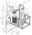
- FIG. 2 is a plan view schematically showing a setup device. It is a perspective view showing a reel supply device to which a reel sorting device is applied.
- FIG. 3 is an enlarged view of the reel holding section in FIG. 2; It is a front view of a reel holding part.
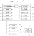
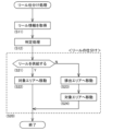
- FIG. 3 is a functional block diagram of a reel loading device. It is a flowchart which shows reel sorting processing. It is a perspective view which shows the discharge unit in the modified form of embodiment.
- a setup device to which a reel sorting device is applied will be explained with reference to the drawings.
- a setup device is a device that performs or assists in various setup operations in preparation for production of a board product.
- a setup device that performs a reel loading operation for loading a reel into a tape feeder as a setup operation will be exemplified.
- the setup device 10 is installed, for example, in a production facility for circuit board products, in an external setup area between a warehouse where parts (not shown) are stored and a production line. In the external setup area, loading the reel 92 onto the feeder 91 may be performed automatically by the setup device 10 or manually by an operator. Further, when multiple types of setup devices 10 corresponding to the types of feeder 91 are installed, these setup devices 10 may be switched and used. Furthermore, feeders 91 and parts may be transported between the external setup area and the warehouse and between the external setup area and the production line by automatic guided vehicles or workers.
- the setup device 10 includes a reel loading device 11, as shown in FIG.
- the reel loading device 11 is a reel working device that performs reel loading work on the feeder 91.
- the reel loading device 11 includes a reel supply device 20 and a reel attachment/detachment device 40.
- the reel supply device 20 temporarily holds a plurality of reels 92 brought in from the outside, and supplies necessary reels 92 to the reel attachment/detachment device 40.
- the reel supply device 20 removably supports the reel holding section 22 on the upper surface of the pedestal 21 .
- the reel holding unit 22 stacks and holds a plurality of reels 92 in a horizontal position (a position in which the rotational axis of the reel 92 faces in the vertical direction).
- the reels 92 held by the reel holding section 22 may include not only unused reels but also partially used reels.
- the reel holding part 22 holds a plurality of reels 92 by having a round bar-shaped holding shaft 24 provided upward from the center of a disc-shaped holding plate 23 passing through the center hole of the reel 92.
- a holding part code 25 indicating identification information (ID) for specifying the reel holding part 22 is attached to the upper surface of the holding plate 23.
- the holding unit code 25 is used to manage the plurality of reels 92 held in the reel holding unit 22.
- the reel supply device 20 includes a reel transfer device 30 as a moving device that moves the reel 92 to the reel attachment/detachment device 40.
- the reel transfer device 30 is provided on the top of the pedestal 21.
- the reel transfer device 30 includes an arm 32 that is movable up and down relative to a column 31 extending in the vertical direction and rotatable around a vertical axis.
- the arm 32 is provided with a collecting section 33 that can be expanded and contracted in the horizontal direction.
- the collection unit 33 removably collects the reel 92 .
- the collection method of the collection unit 33 can adopt various modes.
- the sampling section 33 may grip the peripheral edge or center hole of the reel 92, or may collect the sample by suctioning the upper surface (flange surface in a horizontal position) of the reel 92 with negative pressure air.
- the collecting section 33 is provided with a reader 35.
- the reader 35 reads the holding part code 25 of the reel holding part 22.
- the reader 35 can read the reel code 923 attached to the top reel 92 held by the reel holding section 22 or the reel 92 collected by the collection section 33.
- the reel code 923 indicates identification information (ID) that identifies the reel 92.
- the reel supply device 20 configured as described above is carried into the carry-in area Ac and supplies the plurality of reels 92 held by the reel holding section 22.
- the reel supply device 20 moves one reel 92 collected from the reel holding unit 22 to a target area on the side of the reel attachment/detachment device 40 in a sideways posture by the reel transfer device 30 driving the arm 32 and the collection unit 33. It is placed on Ag (placement area Ap or temporary storage area At).
- the reel transfer device 30 moves the collected reel 92 to the discharge area Ad based on control by the reel sorting device 80, which will be described later. Details of the reel sorting device 80 and details of the operation of the reel transfer device 30 will be described later.
- the reel attachment/detachment device 40 performs the operations of setting reels 92 necessary for production on the feeder 91 and removing reels 92 that are no longer necessary for production from the feeder 91.
- the reel attachment/detachment device 40 includes a feeder holding section 41 that holds a feeder 91 carried in from a feeder supply device 50 described later.
- the feeder 91 When the feeder 91 is held by the feeder holding section 41, it is electrically connected to the setup device 10 via an unillustrated connector. As a result, the feeder 91 becomes capable of communicating with the control device 13 of the setup device 10, which will be described later, and also becomes capable of operating the drive device that feeds and moves the carrier tape 922 unreeled from the loaded reel 92.
- the reel attachment/detachment device 40 includes a setting device 42 that sets a reel 92 on a feeder 91 held by a feeder holding section 41.
- the setting device 42 picks up the reel 92 in the horizontal orientation in the placement area Ap and changes it to the vertical orientation (an orientation in which the rotational axis of the reel 92 faces in the horizontal direction).
- the setting device 42 moves the vertically oriented reel 92 to the feeder 91 and causes the feeder 91 to hold the reel 92.
- the reel 92 that is scheduled to be attached to the feeder 91 held by the feeder holding section 41 is placed in the above-mentioned placement area Ap in a horizontal position. Further, in the temporary storage area At, when it is necessary to change the order in which the setting device 42 sets the plurality of reels 92 on the feeder 91, the reels 92 whose setting order has been postponed are temporarily placed in a horizontal position. .
- the setting device 42 has a tape loading function in which the feeder 91 brings the carrier tape 922 fed out from the reel 92 into a loaded state where it can be fed and moved by a drive device.
- the setting device 42 includes, for example, an articulated robot and an image processing device.
- the setting device 42 recognizes the leading end of the carrier tape 922 using an image processing device.
- the setting device 42 grips the tip of the carrier tape 922 with the fingers of the articulated robot, and engages the feed hole of the carrier tape 922 with a sprocket that constitutes the drive device of the feeder 91 .
- the reel 92 used for production is set on the feeder 91, and the feeder 91 is placed in a loaded state in which the carrier tape 922 can be fed and moved.
- the feeder 91 with the reel 92 set thereon is removed from the feeder holding section 41 and carried out to the feeder supply device 50.
- the reel attaching and detaching device 40 includes a detaching device 43 that detaches the reel 92 from the feeder 91 held by the feeder holding section 41.
- the removal device 43 moves the movable table 46 along the guide rail 45 and removes the reel 92 set on the feeder 91 using the sampling section 47 provided on the movable table 46 .
- the removal device 43 changes the removed reel 92 from a vertical orientation to a horizontal orientation, and inserts the reel 92 into a storage box 49 provided inside the machine.
- Feeder supply device 50 The setup device 10 includes a feeder supply device 50, as shown in FIG.
- the feeder supply device 50 is installed in line with the reel loading device 11, temporarily holds a plurality of feeders brought in from the outside, and supplies necessary feeders 91 to the reel loading device 11.
- the feeder supply device 50 includes a feeder accommodating section 51 and a feeder conveying section 52, which are detachably provided.
- the feeder accommodating section 51 is accommodated in the accommodating space of the housing along with other feeder accommodating sections 51.
- the feeder accommodating portion 51 is formed in a box shape having a horizontal opening.
- the feeder accommodating portion 51 supports the feeder 91 through a plurality of slots formed on the bottom surface.
- the feeder 91 is communicably connected to the setup device 10 via an unillustrated connector.
- the feeder conveying section 52 is configured to be movable between the feeder accommodating section 51 and the feeder holding section 41.
- the feeder transport section 52 takes out an arbitrary feeder 91 from the feeder storage section 51 and carries the feeder 91 into the feeder holding section 41 .
- the reel loading device 11 removes the unnecessary reels 92 from the feeder 91 and loads the reels 92 necessary for the scheduled production into the feeder 91
- the feeder transport section 52 removes the feeder 91 from the feeder holding section 41.
- the feeder 91 is carried out and accommodated in a predetermined slot of the feeder accommodating section 51.
- the setup device 10 includes a control device 13, as shown in FIG.
- the control device 13 controls the operations of the reel loading device 11 and the feeder supply device 50 and performs various operations on the feeder 91.
- the above-mentioned work includes, in addition to the reel loading work as a setup work, the work of simply removing the reel 92 in order to store the feeder 91 without the reel 92 loaded in a warehouse or the like.
- the control device 13 grasps the plurality of reels 92 held in the reel holding part 22 carried into the carry-in area Ac. Further, the control device 13 controls the reel 92 held in the reel holding section 22 or the reel 92 collected in the collecting section 33 of the reel transfer device 30 based on the reading result of the reel code 923 by the reader 35. Understand.
- control device 13 grasps the feeder 91 held in the feeder holding section 41 and the feeder 91 accommodated in the feeder accommodating section 51 through communication.
- the control device 13 loads the reel 92 corresponding to a predetermined feeder 91 or loads the reel 92 into the feeder 91 to be loaded, based on instructions for setup work.
- the control device 13 when the reel 92 is loaded into the feeder 91, the control device 13 generates association information. Furthermore, when the reel 92 is removed from the feeder 91, the control device 13 deletes the association information. The generation and deletion of association information is shared with a management device that is higher-level than the setup device 10, as necessary.
- the carrier tape 922 that accommodates components and the feeder 91 that corresponds to the carrier tape 922 are selected from, for example, a plurality of types depending on the production. Further, the reel loading work is automated by the setup device 10 if the reel loading device 11 is compatible with the type of feeder 91, for example, and is manually performed by an operator if the type is not compatible.
- a plurality of types of reels 92 are mixed and stored in the reel warehouse where the reels 92 to be transported to the external setup area are stored, regardless of whether the reel loading work is performed by the setup device 10 or not. Therefore, before performing the reel loading operation, it is necessary to sort the reels 92 according to the type of reel loading operation (for example, automatic/manual). Therefore, in this embodiment, a configuration is adopted in which the reel sorting process is automated by the reel sorting device 80, thereby making the setup work more efficient.
- the reel sorting device 80 is incorporated into the setup device 10.
- the reel sorting device 80 cooperates with the reel supply device 20 to sort the reels 92 before they are moved from the carry-in area Ac to the target area Ag (temporary storage area At and placement area Ap).
- the reels 92 are sorted into those that are supplied to the reel attachment/detachment device 40 of the reel loading device 11 and those that are discharged from the setup device 10.
- the reels 92 that have been sorted to be discharged from the setup device 10 are discharged in various ways so that they can be taken out by a worker or an automatic guided vehicle.
- the reel sorting device 80 may discharge the reels 92 individually or collectively. Further, the reel sorting device 80 may return the discharged reels 92 to the carry-in area Ac, or may move them to a discharge area Ad different from the target area Ag and the carry-in area Ac.
- a configuration is adopted in which the reels 92 are ejected by moving them individually to the ejection area Ad. Furthermore, in the present embodiment, as shown in FIG. 1, a discharge unit 60 that assists in discharging the reel 92 is installed in the discharge area Ad. In this embodiment, the discharge area Ad is between the carry-in area Ac and the target area Ag when viewed from above, and is set within the movable range of the reel transfer device 30. As shown in FIG. 2, the discharge unit 60 is configured to be able to input the reel 92 held by the collection section 33 of the reel transfer device 30 in a horizontal position.
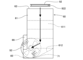
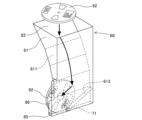
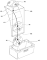
- the discharge unit 60 is configured to be able to hold one reel 92 in the discharge area Ad. As shown in FIGS. 3 and 4, the discharge unit 60 has a shooter 61 as a main body.
- the chute 61 is formed with an input port 62 into which a reel 92 in a horizontal position can be input.
- a first slope 611 is formed in the shooter 61 and is curved so that the reel 92 that has been thrown in the horizontal position slides down and gradually changes to the vertical position.
- a second slope 612 is formed at the bottom of the shooter 61 to support the outer edge of the reel 92 that has been changed to the vertical orientation.
- the second slope 612 is formed to be inclined around the horizontal axis with respect to the horizontal plane, and causes the supported reel 92 to roll under its own weight.
- a stopper 65 is provided at the bottom of the second slope 612. The stopper 65 contacts the reel 92 rolling down the second slope 612 and restricts the rolling of the reel 92.
- a discharge port 66 is formed at the bottom of the shooter 61 to expose a part of the reel 92 held by the second slope 612 and the stopper 65 to the outside.
- the discharge port 66 is a take-out opening that is formed larger than the outer diameter of the reel 92 on one side of the shooter 61 in the width direction (left side in FIG. 4). In this way, when the reel 92 in the horizontal position is inputted from the input port 62, the discharge unit 60 changes the reel 92 to the vertical position while sliding the reel 92 down, and can be taken out from the side discharge port 66. Keep it in the moved position.
- the discharge unit 60 is provided with a reel sensor 71.
- the reel sensor 71 detects the reel 92 whose movement is restricted by the stopper 65 and sends a signal to the reel sorting device 80.
- the reel sensor 71 enters a state in which it is not detecting the reel 92 and stops sending signals to the reel sorting device 80.
- the reel sorting device 80 is incorporated into the control device 13 of the setup device 10, as shown in FIG.
- the reel sorting device 80 can control the operation of the reel transfer device 30 using various functions of the control device 13, input signals from various sensors, and acquire various information by communicating with a higher-level management device. It is composed of Further, the reel sorting device 80 executes reel sorting processing, as shown in FIG.
- the reel sorting device 80 includes a reel information acquisition section 81, as shown in FIG.
- the reel information acquisition unit 81 acquires reel information D10 regarding a reel 92 wound with a carrier tape 922 that accommodates a plurality of components.
- the reel information acquisition unit 81 acquires reel information D10 corresponding to the identification information (ID) read by the reader 35 of the reel transfer device 30 as a moving device for the reel 92 (S11 in FIG. ).
- the reel information acquisition unit 81 transmits the identification information of the reel 92 indicated by the reel code 923 read by the reader 35 to the management device, and acquires it by inputting the reel information D10 corresponding to the identification information. do. Further, when the reader 35 reads the holding unit code 25, it transmits the identification information of the reel holding unit 22 to the management device, and transmits the identification information of the plurality of reels 92 held by the reel holding unit 22 to the stack of reels 92. It may also be acquired along with the order.
- the reel information D10 includes feeder designation information D11 that designates the type of feeder 91 into which the reel 92 is loaded.
- feeder designation information D11 that designates the type of feeder 91 into which the reel 92 is loaded.
- some types of feeder 91 have different width dimensions depending on the type of carrier tape 922, and some feeders may have different width dimensions depending on the type of carrier tape 922, or may be capable of preliminarily setting a supply carrier tape 922 in addition to the carrier tape 922 in use. It includes a device that automatically feeds and moves a replenishing carrier tape 922 when the carrier tape 922 is finished.
- the feeder specification information D11 of the reel information D10 specifies one or more types of feeders 91 that allow loading of the reel 92.
- the types of feeders 91 to be specified include those for which the reel loading work can be performed by the setup device 10 and those for which the reel loading work can be performed only manually by the operator. Note that if the type of feeder 91 to be loaded on a predetermined reel 92 is not designated, the reel information D10 does not include the feeder designation information D11.
- the reel sorting device 80 includes a determination section 82, as shown in FIG.
- the determination unit 82 executes a determination process of whether or not to supply the reel 92 to the reel loading device 11 based on the acquired reel information D10 (S12 in FIG. 6). In other words, the determination unit 82 determines whether or not the reel 92 carried into the reel supply device 20 is to be supplied to the reel attachment/detachment device 40 that performs loading work in the reel loading device 11 .
- the determination unit 82 can perform determination processing based on various conditions. For example, the determination unit 82 may perform the determination process based on whether or not the type of feeder 91 designated by the feeder designation information D11 can be loaded by the reel loading device 11. Thereby, the reel 92 to be determined is determined to be supplied to the reel attachment/detachment device 40 when the designated feeder 91 corresponds to the reel loading device 11 .
- the determination unit 82 determines correspondence information indicating whether loading by the reel loading device 11 is possible for each type of feeder 91 and type of reel 92. The determination may be made based on D30.
- the correspondence information D30 records operations that can be performed by the setup device 10 for each type of feeder 91 and reel 92 that can be carried into the setup device 10.
- the determination unit 82 determines the type of feeder 91 and the type of the reel 92 into which the reel 92 is scheduled to be loaded based on the combination information D20. Determination and determination processing may also be performed.
- the above combination information D20 is information indicating the combination of the feeder 91 and reel 92 used for each production of board products.
- the determination unit 82 may perform the determination process based on the instruction information D40 that instructs to omit the loading operation regardless of whether or not the reel loading device 11 can perform the loading operation.
- the determination unit 82 basically performs determination processing based on whether the reel 92 that has been brought in and the feeder 91 to be loaded are compatible with the setup device 10. However, in the setup device 10, when scheduled production is canceled or when there is an interruption in production and it becomes necessary for a worker to quickly perform manual setup work and transport the equipment to the production line, The work may become unnecessary.
- the determination unit 82 determines that the reel 92 is not to be supplied to the reel loading device 11 so as not to perform the loading operation if the loading operation is ultimately instructed to be skipped. do.
- Sorting section 83 The reel sorting device 80 includes a sorting section 83, as shown in FIG.
- the sorting unit 83 sorts the reels 92 based on the result of the determination process (S20 in FIG. 6). In this embodiment, the sorting unit 83 sorts the reels 92 by switching the movement target of the reels 92 by the reel transfer device 30 based on the result of the determination process.
- the reel transfer device 30 transfers the reel 92 carried into the carry-in area Ac to the placement area Ap or the temporary storage area At of the target area Ag as an initial movement target. Then, when it is determined by the determination process that the reel 92 is to be supplied (S21 in FIG. 6: Yes), the sorting unit 83 moves the reel 92 to the target area Ag (S22). On the other hand, if it is determined by the determination process that the reel 92 is not to be supplied (S21: No), the sorting unit 83 switches the movement target to the discharge area Ad and moves the reel 92 to the discharge area Ad (S23).
- the reel 92 that has been moved to the discharge area Ad is released from the collection section 33 of the reel transfer device 30 above the input port 62 of the discharge unit 60, and is loaded from the input port 62.
- the reel 92 is changed from a horizontal position to a vertical position by the shooter 61 and is guided to the discharge port 66.
- the reel 92 is held in the discharge unit 60 in a state in which movement is restricted by the stopper 65 and can be taken out to the outside.
- the discharge unit 60 of this embodiment is configured to be able to hold only one reel 92. Therefore, in the reel sorting process that continues after the reels 92 are input into the discharge unit 60, when the reels 92 need to be discharged again, the sorting section 83 is configured to remove the previously discharged reels 92 from the operator or the like. Insertion of the reel 92 into the discharge unit 60 is waited until the reel 92 is taken out. When the previously discharged reel 92 is taken out, the sorting section 83 restarts the operation of inserting the reel 92.
- the reel sorting device 80 includes a storage section 84, as shown in FIG.
- the storage unit 84 is configured by a storage device such as a hard disk device or a flash memory.
- the storage unit 84 records control programs necessary for executing setup work, work command information according to a production plan acquired from a higher-level management device, and the like. Furthermore, the storage unit 84 records an execution log of the determination process by the determination unit 82 and an execution log of the sorting operation by the sorting unit 83.
- the storage unit 84 stores reel information D10, combination information D20, correspondence information D30, and instruction information D40.
- This information is input by an operator via an unillustrated input device provided in the setup device 10, for example, or is acquired through communication from a higher-level management device. Further, this information is updated as appropriate in response to changes in the production plan, and maintained in synchronization with the management device.
- the reel sorting device 80 includes a detection section 85, as shown in FIG.
- the detection unit 85 detects the reel 92 held by the discharge unit 60. Specifically, when the reel 92 introduced into the discharge unit 60 is guided to the discharge port 66 and held in a state where movement is regulated by the stopper 65, the reel sensor 71 provided in the discharge unit 60 detects the reel 92. is detected and a signal is sent out.
- the detection unit 85 recognizes that the reel 92 is removably present in the discharge unit 60 while inputting the above signal. For example, when the reel 92 is taken out from the discharge unit 60 by a worker and the reel sensor 71 stops sending out the signal, the detection unit 85 recognizes that the discharge unit 60 is not holding the reel 92.
- the reel sorting device 80 includes a notification section 86, as shown in FIG.
- the notification unit 86 sends notifications when it is determined through the determination process that the reel 92 is not to be supplied (S21 in FIG. 6: No), or when the reel 92 is moved to a predetermined area as a result of the determination process (S22, S23). ), the operator is notified according to the result of the determination process (S24).
- the notification unit 86 performs notification processing to notify the worker, for example, when the detection unit 85 detects the reel 92 to be ejected (when the reel 92 is moved to the ejection area Ad as a result of the determination process). Execute.
- the notification process is performed by lighting an indicator light or sending a notification to a terminal device carried by the worker. Further, the notification unit 86 may execute the notification process when the determination unit 82 determines that the reel 92 is not to be supplied to the reel attachment/detachment device 40 of the reel loading device 11 regardless of the detection result by the detection unit 85. good. Furthermore, when the reel 92 is returned to the original carry-in area Ac based on the result of the determination process, the notification unit 86 may notify the operator to that effect.
- the operator can recognize that there is a reel 92 to be ejected in the setup device 10. This prompts the operator to take out the reel 92 from the setup device 10, allowing the operator to quickly start the setup work that should be done manually.
- the reel sorting device 80 is configured to input reels 92 that have been determined not to be supplied to the reel loading device 11 into the discharge unit 60 installed in the discharge area Ad.
- This discharge unit 60 is configured to be able to hold only one reel 92.
- the ejection unit 160 of the reel loading device 11 may include a reel box 167 that can accommodate a plurality of reels 92 in the ejection area Ad.
- the discharge unit 160 has a shooter 161 in which an input port 62 into which a reel 92 in a horizontal position can be input is formed.
- the shooter 161 is formed with a first slope 611 that is curved so that the reel 92 that has been thrown in the horizontal position slides downward and gradually changes to the vertical position.
- a discharge port 166 is formed in the lower part of the shooter 61 to allow the reel 92, which has been changed to the vertical orientation, to drop downward.
- a reel box 167 is arranged below the discharge port 166.
- the plurality of reels 92 determined not to be supplied to the reel loading device 11 are discharged to the reel box 167 as the reel sorting process is executed. Thereby, the worker can take out the plurality of reels 92 accumulated in the reel box 167 at once.
- the number of reels 92 that are determined not to be supplied to the reel loading device 11 and are input into the discharging unit 160 reaches a predetermined value or more. In such a case, the operator may be notified of this fact.
- the reel loading device 11 is illustrated as having the ejection units 60 and 160.
- the reel loading device 11 may be configured without the ejection units 60 and 160. Specifically, when it is determined by the determination process that the reel 92 is not to be supplied, the sorting unit 83 switches the movement target from the target area Ag to the carry-in area Ac, and moves the reel 92 back to the carry-in area Ac. .
- the reader 35 may read the reel code 923 of the uppermost reel 92 held by the reel holding unit 22 without the collecting unit 33 collecting the reel 92 . At this time, if it is determined that the reel 92 is not to be supplied to the reel loading device, the process of moving the reel 92 to the carry-in area Ac by the sorting unit 83 is omitted, and the notification process by the notification unit 86 is executed as necessary. be done.
- the reel sorting device 80 is installed in the setup device 10 installed in an external setup area.
- the reel sorting device 80 may be configured as an external device of the setup device 10 as long as it is capable of performing reel sorting processing on the plurality of reels 92 before being carried into the setup device 10.
- the reel sorting device may be configured as a device dedicated to reel sorting processing that is installed alongside the setup device 10 in an external setup area, similar to the setup device 10.
- the reel sorting device has the same function as the reel transfer device 30 of the setup device 10, and separates the reel 92 to be supplied to the reel loading device 11 of the setup device 10 and the other reels 92. Sort.
- the reel sorting device may be incorporated into a warehouse where the reels 92 are stored.
- the reel sorting device acquires reel information D10 about the plurality of reels 92 to be delivered from the warehouse, determines whether or not to supply the reel to the reel loading device 11, and based on the result of this determination process, reel information D10 is acquired.
- Sort 92 For example, a warehouse is provided with a plurality of exit ports in advance, or a plurality of reel holding parts 22 are supported at the exit exit, and the plurality of reels 92 are exited from the warehouse in a sorted state. Such a configuration also provides the same effects as the embodiment.
Landscapes
- Engineering & Computer Science (AREA)
- Manufacturing & Machinery (AREA)
- Microelectronics & Electronic Packaging (AREA)
- Operations Research (AREA)
- Supply And Installment Of Electrical Components (AREA)
Priority Applications (5)
| Application Number | Priority Date | Filing Date | Title |
|---|---|---|---|
| CN202280096751.0A CN119234474A (zh) | 2022-07-28 | 2022-07-28 | 带盘分类装置 |
| PCT/JP2022/029094 WO2024024016A1 (ja) | 2022-07-28 | 2022-07-28 | リール仕分け装置 |
| DE112022007600.3T DE112022007600T5 (de) | 2022-07-28 | 2022-07-28 | Spulensortiervorrichtung |
| JP2024536673A JPWO2024024016A1 (cg-RX-API-DMAC7.html) | 2022-07-28 | 2022-07-28 | |
| US18/874,766 US20260167452A1 (en) | 2022-07-28 | 2022-07-28 | Reel sorting apparatus |
Applications Claiming Priority (1)
| Application Number | Priority Date | Filing Date | Title |
|---|---|---|---|
| PCT/JP2022/029094 WO2024024016A1 (ja) | 2022-07-28 | 2022-07-28 | リール仕分け装置 |
Publications (1)
| Publication Number | Publication Date |
|---|---|
| WO2024024016A1 true WO2024024016A1 (ja) | 2024-02-01 |
Family
ID=89705741
Family Applications (1)
| Application Number | Title | Priority Date | Filing Date |
|---|---|---|---|
| PCT/JP2022/029094 Ceased WO2024024016A1 (ja) | 2022-07-28 | 2022-07-28 | リール仕分け装置 |
Country Status (5)
| Country | Link |
|---|---|
| US (1) | US20260167452A1 (cg-RX-API-DMAC7.html) |
| JP (1) | JPWO2024024016A1 (cg-RX-API-DMAC7.html) |
| CN (1) | CN119234474A (cg-RX-API-DMAC7.html) |
| DE (1) | DE112022007600T5 (cg-RX-API-DMAC7.html) |
| WO (1) | WO2024024016A1 (cg-RX-API-DMAC7.html) |
Citations (3)
| Publication number | Priority date | Publication date | Assignee | Title |
|---|---|---|---|---|
| JP6334538B2 (ja) * | 2013-08-21 | 2018-05-30 | 株式会社Fuji | フィーダ部品種決定方法およびフィーダ部品種決定装置 |
| WO2021199288A1 (ja) * | 2020-03-31 | 2021-10-07 | 株式会社Fuji | テープ装填装置 |
| WO2022137379A1 (ja) * | 2020-12-23 | 2022-06-30 | 株式会社Fuji | 基板生産システム |
-
2022
- 2022-07-28 WO PCT/JP2022/029094 patent/WO2024024016A1/ja not_active Ceased
- 2022-07-28 CN CN202280096751.0A patent/CN119234474A/zh active Pending
- 2022-07-28 US US18/874,766 patent/US20260167452A1/en active Pending
- 2022-07-28 DE DE112022007600.3T patent/DE112022007600T5/de active Pending
- 2022-07-28 JP JP2024536673A patent/JPWO2024024016A1/ja active Pending
Patent Citations (3)
| Publication number | Priority date | Publication date | Assignee | Title |
|---|---|---|---|---|
| JP6334538B2 (ja) * | 2013-08-21 | 2018-05-30 | 株式会社Fuji | フィーダ部品種決定方法およびフィーダ部品種決定装置 |
| WO2021199288A1 (ja) * | 2020-03-31 | 2021-10-07 | 株式会社Fuji | テープ装填装置 |
| WO2022137379A1 (ja) * | 2020-12-23 | 2022-06-30 | 株式会社Fuji | 基板生産システム |
Also Published As
| Publication number | Publication date |
|---|---|
| JPWO2024024016A1 (cg-RX-API-DMAC7.html) | 2024-02-01 |
| CN119234474A (zh) | 2024-12-31 |
| US20260167452A1 (en) | 2026-06-18 |
| DE112022007600T5 (de) | 2025-05-15 |
Similar Documents
| Publication | Publication Date | Title |
|---|---|---|
| CN115004879A (zh) | 带盘拆装装置及供料器准备系统 | |
| CN116491239B (zh) | 基板生产系统 | |
| JP7728942B2 (ja) | 部品実装ライン | |
| JP6956186B2 (ja) | バーを取り扱うための装置と方法 | |
| DE112023005667T5 (de) | Zuführerlagersystem | |
| WO2017216832A1 (ja) | フィーダ管理方法およびフィーダ管理装置 | |
| JP2009218463A (ja) | ノズル回収装置、ノズル回収装置を備えた実装装置および回収ノズルのメンテナンス方法 | |
| JP2026074145A (ja) | セットアップ装置 | |
| CN217577255U (zh) | 全自动激光蚀刻分拣机 | |
| KR20220098173A (ko) | 기판 매거진의 로딩 및 언로딩 장치, 기판 매거진 시스템 | |
| KR100351668B1 (ko) | 부품공급장치및부품공급방법 | |
| JP7536194B2 (ja) | フィーダセットアップ装置およびフィーダセットアップシステム | |
| JP7680541B2 (ja) | フィーダセットアップ装置 | |
| WO2025143223A1 (ja) | テープ自動キッティング装置 | |
| CN119234474A (zh) | 带盘分类装置 | |
| JPH10224086A (ja) | 電子部品装着システム | |
| CN219519622U (zh) | 石墨舟卡点的分类回收机构和石墨舟卡点的自动拆装设备 | |
| US20250380393A1 (en) | Reel work device | |
| JP7329744B2 (ja) | ノズル管理装置 | |
| JP7761680B2 (ja) | リール装填装置 | |
| US20250171261A1 (en) | Setup system and setup method | |
| WO2021070390A1 (ja) | ノズル管理装置 | |
| CN115870246B (zh) | 一种料盒内硅片的收取方法 | |
| JP7437669B2 (ja) | ノズル管理装置 | |
| JP7808134B2 (ja) | テープ自動処理装置及びリール装填装置 |
Legal Events
| Date | Code | Title | Description |
|---|---|---|---|
| 121 | Ep: the epo has been informed by wipo that ep was designated in this application |
Ref document number: 22953108 Country of ref document: EP Kind code of ref document: A1 |
|
| WWE | Wipo information: entry into national phase |
Ref document number: 2024536673 Country of ref document: JP |
|
| WWE | Wipo information: entry into national phase |
Ref document number: 202280096751.0 Country of ref document: CN |
|
| WWE | Wipo information: entry into national phase |
Ref document number: 18874766 Country of ref document: US |
|
| WWP | Wipo information: published in national office |
Ref document number: 202280096751.0 Country of ref document: CN |
|
| WWE | Wipo information: entry into national phase |
Ref document number: 112022007600 Country of ref document: DE |
|
| WWP | Wipo information: published in national office |
Ref document number: 112022007600 Country of ref document: DE |
|
| 122 | Ep: pct application non-entry in european phase |
Ref document number: 22953108 Country of ref document: EP Kind code of ref document: A1 |
|
| WWP | Wipo information: published in national office |
Ref document number: 18874766 Country of ref document: US |