WO2024023985A1 - 数値制御装置および数値制御プログラム - Google Patents
数値制御装置および数値制御プログラム Download PDFInfo
- Publication number
- WO2024023985A1 WO2024023985A1 PCT/JP2022/028998 JP2022028998W WO2024023985A1 WO 2024023985 A1 WO2024023985 A1 WO 2024023985A1 JP 2022028998 W JP2022028998 W JP 2022028998W WO 2024023985 A1 WO2024023985 A1 WO 2024023985A1
- Authority
- WO
- WIPO (PCT)
- Prior art keywords
- workpiece
- normal direction
- processing
- gap amount
- numerical control
- Prior art date
- Legal status (The legal status is an assumption and is not a legal conclusion. Google has not performed a legal analysis and makes no representation as to the accuracy of the status listed.)
- Ceased
Links
Images





Classifications
-
- B—PERFORMING OPERATIONS; TRANSPORTING
- B23—MACHINE TOOLS; METAL-WORKING NOT OTHERWISE PROVIDED FOR
- B23K—SOLDERING OR UNSOLDERING; WELDING; CLADDING OR PLATING BY SOLDERING OR WELDING; CUTTING BY APPLYING HEAT LOCALLY, e.g. FLAME CUTTING; WORKING BY LASER BEAM
- B23K26/00—Working by laser beam, e.g. welding, cutting or boring
- B23K26/02—Positioning or observing the workpiece, e.g. with respect to the point of impact; Aligning, aiming or focusing the laser beam
- B23K26/03—Observing, e.g. monitoring, the workpiece
-
- B—PERFORMING OPERATIONS; TRANSPORTING
- B23—MACHINE TOOLS; METAL-WORKING NOT OTHERWISE PROVIDED FOR
- B23K—SOLDERING OR UNSOLDERING; WELDING; CLADDING OR PLATING BY SOLDERING OR WELDING; CUTTING BY APPLYING HEAT LOCALLY, e.g. FLAME CUTTING; WORKING BY LASER BEAM
- B23K26/00—Working by laser beam, e.g. welding, cutting or boring
- B23K26/02—Positioning or observing the workpiece, e.g. with respect to the point of impact; Aligning, aiming or focusing the laser beam
- B23K26/04—Automatically aligning, aiming or focusing the laser beam, e.g. using the back-scattered light
- B23K26/046—Automatically focusing the laser beam
- B23K26/048—Automatically focusing the laser beam by controlling the distance between laser head and workpiece
Definitions
- the present disclosure relates to a numerical control device that controls a machine tool.
- Some machine tools perform relative movement between a processing nozzle and a workpiece, and also irradiate a laser beam from the processing nozzle toward the processing surface of the workpiece to perform laser processing on the processing surface.
- Some numerical control devices that control such machine tools detect the "gap amount” as the shortest distance from the machining nozzle to the machining surface, and adjust the gap amount by feedback control based on the detected gap amount. There is a method that corrects the gap amount to a desired amount.
- processing surface direction the direction perpendicular to the processing surface
- irradiation direction the direction of laser irradiation by the processing nozzle
- the laser may be irradiated with the irradiation direction tilted with respect to the normal direction, for example in the case of bevel processing to form a V-shaped groove in cross-sectional view.
- the workpiece and the processing nozzle may deviate from the desired relative position, and the gap amount may deviate from the desired gap amount.
- the relative position between the workpiece and the processing nozzle is controlled in the direction of the processing surface, the relative position between the processing nozzle and the workpiece will deviate from the desired relative position in the normal direction. Since the irradiation direction is inclined with respect to the normal direction, the deviation in the normal direction causes the laser irradiation position on the processing surface to also deviate from the desired irradiation position.
- the gap amount is corrected by relatively moving the machining nozzle and workpiece in the irradiation direction from this state, the gap amount will only be corrected to the desired gap amount, and the laser irradiation position on the processing surface will be Since the direction of the relative movement is the irradiation direction, the deviated position is maintained and the desired irradiation position is not corrected.
- the present disclosure has been made in view of the above circumstances, and aims to make it possible to correct the laser irradiation position on the processing surface in addition to correcting the gap amount.
- the numerical control device of the present disclosure includes: A numerical control device that controls a machine tool that performs relative movement between a processing nozzle and a workpiece and laser-processes the processing surface of the workpiece by irradiating a laser beam from the processing nozzle toward the processing surface of the workpiece, comprising: a gap amount acquisition unit that acquires a gap amount as the shortest distance from the processing nozzle to the processing surface; a normal calculation unit that calculates the normal direction of the processed surface; a movement amount calculation unit that calculates a normal movement amount as a movement amount for making the gap amount a desired gap amount by relatively moving the processing nozzle and the workpiece in the calculated normal direction; a gap correction unit that corrects the gap amount to the desired gap amount by relatively moving the processing nozzle and the workpiece in the normal direction based on the calculated normal direction movement amount; has.
- the processing nozzle and the workpiece are relatively moved not in the laser irradiation direction but in the normal direction of the processing surface, thereby correcting the gap amount.
- the irradiation position on the processing surface can be corrected.
- the numerical control program of the present disclosure is computer, A numerical control device that controls a machine tool that performs relative movement between a processing nozzle and a workpiece and laser-processes the processing surface of the workpiece by irradiating a laser beam from the processing nozzle toward the processing surface of the workpiece;
- a numerical control program that functions as The computer further comprises: a gap amount acquisition unit that acquires a gap amount as the shortest distance from the processing nozzle to the processing surface; a normal calculation unit that calculates the normal direction of the processed surface; a movement amount calculation unit that calculates a normal movement amount as a movement amount for making the gap amount a desired gap amount by relatively moving the processing nozzle and the workpiece in the calculated normal direction; a gap correction unit that corrects the gap amount to the desired gap amount by relatively moving the processing nozzle and the workpiece in the normal direction based on the calculated normal direction movement amount; function as
- the numerical control program of the present disclosure it is possible to cause a computer to function as the numerical control device of the present disclosure. Thereby, as in the case of the numerical control device of the present disclosure, it is possible to correct the gap amount and the irradiation position on the processing surface.
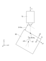
- FIG. 3 is a side view showing a situation in which a laser beam is obliquely irradiated onto a processed surface. It is a side view which shows the case where a workpiece shifts
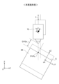
- FIG. 7 is a side view showing gap correction in a comparative example.
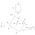
- FIG. 3 is a side view showing gap correction in this embodiment.
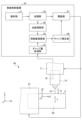
- 2 is a schematic diagram showing a numerical control device from a different perspective from FIG. 1.
- FIG. It is a schematic diagram showing a numerical control device of a 2nd embodiment.
- FIG. 3 is a side view showing a state in which the first processing surface is selected as the current processing surface.
- FIG. 7 is a side view showing a state in which the second processing surface is selected as the current processing surface.
- the numerical control device 50 controls the machine tool 90 based on commands based on numerical information.
- the three directions that are orthogonal to each other will be referred to as the "X direction,”"Ydirection,” and "Z direction.”
- the X direction and the Y direction are two directions that are perpendicular to each other in a horizontal plane, and the Z direction is a vertical direction.
- the machine tool 90 includes a nozzle holding section 71 that holds a processing nozzle 72 and a workpiece holding section 81 that holds a workpiece 82.
- the machine tool 90 moves the processing nozzle 72 and the workpiece 82 relative to each other by moving the nozzle holding part 71 and the workpiece holding part 81 relative to each other.
- the relative movement may include all or all of the following: relative movement in the X direction, relative movement in the Y direction, relative movement in the Z direction, relative movement in the X direction, relative movement in the Y direction, relative movement in the Z direction. Including some.
- Each of these relative movements may be performed by moving the processing nozzle 72, by moving the workpiece 82, or by moving both the processing nozzle 72 and the workpiece 82. Good too.
- the machine tool 90 performs laser processing by irradiating the workpiece 82 with the laser Lb from the processing nozzle 72.
- irradiation direction I the direction in which the laser Lb is irradiated by the processing nozzle 72
- processing surface S the surface of the workpiece 82 that is irradiated with the laser Lb
- processing surface direction sX, sY the two-dimensional direction along the processing surface S
- processing surface direction sX, sY the normal to the processing surface S
- the direction is called "normal direction sZ.” Further, hereinafter, the shortest distance between the tip of the processing nozzle 72 and the processing surface S, that is, the distance in the normal direction sZ, will be referred to as a "gap amount G.”
- the processing nozzle 72 has a gap amount detection device 78 for detecting the gap amount G.
- the gap amount detection device 78 detects the gap amount G based on the capacitance between the tip of the processing nozzle 72 and the workpiece 82, for example.
- the numerical control device 50 is configured such that a machining program can be input by a user or the like, and controls the machine tool 90 based on the input machining program.
- the numerical control device 50 includes an analysis section 21, a processing section 22, and a drive section 27.
- the analysis unit 21 analyzes the input machining program.
- the processing section 22 calculates the amount of movement of the nozzle holding section 71 and the workpiece holding section 81 in order to bring the processing nozzle 72 and the workpiece 82 into desired relative positions based on the analysis result by the analysis section 21 .
- the drive unit 27 outputs an operation command to the machine tool 90 based on the calculation result by the processing unit 22.
- the numerical control device 50 further includes a gap amount acquisition section 33 and a gap correction section 36.
- the gap amount acquisition unit 33 acquires the gap amount G detected by the gap amount detection device 78 from the gap amount detection device 78.
- the gap correction section 36 corrects the gap amount G to a desired gap amount Go by performing feedback control or the like based on the gap amount G acquired by the gap amount acquisition section 33.
- the laser in laser processing, the laser is irradiated with the irradiation direction I tilted with respect to the normal direction sZ, for example in the case of bevel processing to form a V-shaped groove in a cross-sectional view.
- the workpiece 82 and the processing nozzle 72 may deviate from the desired relative position, and the gap amount G may deviate from the desired gap amount Go.
- the relative position between the workpiece 82 and the processing nozzle 72 is controlled in the processing surface directions sX and sY, the relative position of the workpiece 82 with respect to the processing nozzle 72 changes from the desired position 82o shown by the broken line in FIG.
- the processing nozzle 72 and the workpiece 82 are relatively moved in the irradiation direction I to correct the gap amount G, as in the case of the comparative example shown in FIG. 4, for example.
- the gap amount G is only corrected to the desired gap amount Go, and the irradiation position P on the processing surface S is maintained at a shifted position because the direction of the relative movement is the irradiation direction I.
- the irradiation position is not corrected to the desired irradiation position Po.
- the numerical control device 50 further includes a normal calculation unit 44 and a movement amount calculation unit 45, as shown in FIG.
- the normal calculation unit 44 recognizes the rotation angle ⁇ of the workpiece 82 from a predetermined reference state and calculates the normal direction sZ based on the machining program.
- the normal calculation unit 44 calculates the reference normal direction sZo as the normal direction sZ when the workpiece 82 is in the reference state, and the reference state of the workpiece 82 based on the machining program.
- the normal direction sZ is calculated based on the rotation angle ⁇ . In other words, the direction obtained by rotating the reference normal direction sZo by the rotation angle ⁇ becomes the normal direction sZ.
- the Z direction is the reference normal direction sZo and the workpiece 82 is rotated around the X direction.
- the unit vector (Xu, Yu, Zu) in the normal direction sZ that is, the vector whose absolute value is "1"
- the normal calculation unit 44 calculates the normal direction sZ by calculating this unit vector (Xu, Yu, Zu).
- the movement amount calculation unit 45 calculates the “normal direction movement amount V” as the relative movement amount in the normal direction sZ between the processing nozzle 72 and the workpiece 82 for correcting the gap amount G shown in FIG. 3 to the desired gap amount Go. ” is calculated.
- the normal direction movement amount V can be determined from, for example, the difference between the gap amount G and the desired gap amount Go, and the angle of the irradiation direction I with respect to the normal direction sZ.
- the gap correction unit 36 moves the processing nozzle 72 and the workpiece 82 in the X direction, Y direction, and Z direction by the amount of each component in this normal direction movement vector (Xv, Yv, Zv). relative movement in each direction.
- the processing nozzle 72 and the workpiece 82 are relatively moved in the normal direction sZ by the normal direction movement amount V.
- the gap amount G is corrected to the desired gap amount Go, and the laser irradiation position P on the processing surface S is also corrected to the desired irradiation position Po.
- the numerical control device 50 shown above is mainly composed of, for example, a computer Cp and a numerical control program 50p.
- the computer Cp has a CPU, RAM, ROM, etc.
- the numerical control program 50p is a program for causing the computer Cp to function as the numerical control device 50 in cooperation with the computer Cp.
- the numerical control program 50p includes an analysis program 21p, a processing program 22p, a drive program 27p, a normal calculation program 44p, a movement amount calculation program 45p, a gap amount acquisition program 33p, and a gap correction program 36p.
- the analysis program 21p causes the computer Cp to function as the analysis section 21.
- the processing program 22p causes the computer Cp to function as the processing unit 22.
- the drive program 27p causes the computer Cp to function as the drive section 27.
- the normal calculation program 44p causes the computer Cp to function as the normal calculation unit 44.
- the movement amount calculation program 45p causes the computer Cp to function as the movement amount calculation section 45.
- the gap amount acquisition program 33p causes the computer Cp to function as the gap amount acquisition section 33.
- the gap correction program 36p causes the computer Cp to function as the gap correction section 36.
- the normal calculation unit 44 calculates the normal direction sZ of the processing surface S.
- the movement amount calculation unit 45 calculates a "normal direction movement amount V" for relatively moving the processing nozzle 72 and the workpiece 82 in the calculated normal direction sZ to make the gap amount G a desired gap amount Go.
- the gap correction unit 36 corrects the gap amount G to the desired gap amount Go by relatively moving the processing nozzle 72 and the workpiece 82 in the normal direction sZ by the calculated normal direction movement amount V. In this way, when correcting the gap amount G, by relatively moving the processing nozzle 72 and the workpiece 82 not in the irradiation direction I but in the normal direction sZ, it is possible to correct not only the gap amount G but also the processing surface S. It is also possible to correct the irradiation position P in .
- the normal calculation unit 44 calculates, based on the reference normal direction sZo as the normal direction sZ when the workpiece 82 is in a predetermined reference state, and the rotation angle ⁇ of the workpiece 82 from the reference state based on the machining program. Calculate the normal direction sZ. Therefore, the normal direction sZ can be calculated simply and efficiently.
- the numerical control device 50 is mainly composed of a computer Cp and a numerical control program 50p, and the numerical control program 50p causes the computer Cp to function as the numerical control device 50. Therefore, the numerical control device 50 of this embodiment can be implemented using the computer Cp.
- the numerical control device 50 further includes a current machining surface changing section 43.
- the current machining surface changing unit 43 selects one of the plurality of machining surfaces S as the current machining surface Sc based on the preset shape of the workpiece 82 and the rotation angle ⁇ of the workpiece 82 from the reference state. do.
- the workpiece 82 has a quadrangular prism shape with both end faces in the X direction having rectangular shapes. That is, as shown in FIG. 8, the workpiece 82 has a rectangular shape when viewed in the X direction.
- the workpiece 82 has a first machining surface S1 as a machining surface S on one long side, a second machining surface S2 as a machining surface S on one short side, and a first machining surface. It has a third processed surface S3 as a processed surface S on the opposite side to S1, and a fourth processed surface S4 as a processed surface on the opposite side to the second processed surface S2.
- the Z direction is the reference normal direction sZo and the work 82 is rotated around the X direction.
- a state in which the "first normal direction sZ1" which is the normal direction sZ of the first processing surface S1 is the reference normal direction sZo is referred to as a "reference state"
- the first normal direction with respect to the reference normal direction sZo is The angle in the normal direction sZ1 is defined as "rotation angle ⁇ of the workpiece 82.”
- the current machining surface changing unit 43 selects the first machining surface S1 as the current machining surface Sc when the rotation angle ⁇ of the workpiece 82 is between ⁇ 45° and 45°.
- the second machining surface S2 is selected as the current machining surface Sc.
- the third processing surface S3 is selected as the current processing surface Sc.
- the fourth machining surface S4 is selected as the current machining surface Sc.
- the normal calculation unit 44 shown in FIG. 7 calculates the normal direction sZ of the selected current processing surface Sc.
- the movement amount calculating section 45 calculates a normal direction movement amount V for making the calculated gap amount G in the normal direction sZ a desired gap amount Go.
- the gap correction unit 36 relatively moves the processing nozzle 72 and the workpiece 82 by the calculated normal direction movement amount V in the normal direction sZ of the current processing surface Sc.
- the gap amount G is corrected to the desired gap amount Go
- the irradiation position P is corrected to the desired irradiation position Po.
- the current machining surface changing unit 43 selects one of the plurality of machining surfaces S as the current machining surface Sc based on the rotation angle ⁇ of the workpiece 82.
- the normal calculation unit 44 calculates the normal direction sZ of the current processing surface Sc.
- the gap correction unit 36 relatively moves the processing nozzle 72 and the workpiece 82 in the normal direction sZ of the current processing surface Sc. Therefore, even if the workpiece 82 has a plurality of machining surfaces S, such as when the workpiece 82 is a square pipe, this can be handled without changing the settings for the machining surfaces S.
- the embodiment shown above can be modified as follows, for example.
- the numerical control device 50 may be composed of a device exclusively for numerical control.
- Movement amount calculation unit 50 Numerical control device 50p Numerical control program 72 Machining nozzle 82 Work 90 Machine tool Cp Computer G Gap amount Go Desired gap amount S Machining surface sZ Normal direction sZo Reference normal direction ⁇ Workpiece rotation angle
Landscapes
- Physics & Mathematics (AREA)
- Optics & Photonics (AREA)
- Engineering & Computer Science (AREA)
- Plasma & Fusion (AREA)
- Mechanical Engineering (AREA)
- Numerical Control (AREA)
- Laser Beam Processing (AREA)
Abstract
Description
加工ノズルとワークとの相対移動を行うと共に前記加工ノズルから前記ワークの加工面に向けてレーザを照射することによって前記加工面をレーザ加工する工作機械を、制御する数値制御装置であって、
前記加工ノズルから前記加工面までの最短距離としてのギャップ量を取得するギャップ量取得部と、
前記加工面の法線方向を演算する法線演算部と、
演算された前記法線方向に前記加工ノズルと前記ワークとを相対移動させて前記ギャップ量を所望ギャップ量にするための移動量としての法線方向移動量を演算する移動量演算部と、
演算された前記法線方向移動量に基づいて、前記加工ノズルと前記ワークとを前記法線方向に相対移動させることによって、前記ギャップ量を前記所望ギャップ量に補正するギャップ補正部と、
を有する。
コンピュータを、
加工ノズルとワークとの相対移動を行うと共に前記加工ノズルから前記ワークの加工面に向けてレーザを照射することによって前記加工面をレーザ加工する工作機械を、制御する数値制御装置、
として機能させる数値制御プログラムであって、
前記コンピュータを、さらに、
前記加工ノズルから前記加工面までの最短距離としてのギャップ量を取得するギャップ量取得部と、
前記加工面の法線方向を演算する法線演算部と、
演算された前記法線方向に前記加工ノズルと前記ワークとを相対移動させて前記ギャップ量を所望ギャップ量にするための移動量としての法線方向移動量を演算する移動量演算部と、
演算された前記法線方向移動量に基づいて、前記加工ノズルと前記ワークとを前記法線方向に相対移動させることによって、前記ギャップ量を前記所望ギャップ量に補正するギャップ補正部と、
として機能させる。
まず、図1を参照しつつ、本実施形態の数値制御装置50の構成について説明する。数値制御装置50は、数値情報による指令によって工作機械90を制御する。以下、互いに直交し合う3方向を「X方向」「Y方向」「Z方向」という。具体的には、例えばX方向およびY方向は、水平面内において互いに直交し合う2方向であり、Z方向は鉛直方向である。


次に図7~図9を参照しつつ、第2実施形態について説明する。本実施形態については、第1実施形態をベースにこれと異なる点を中心に説明し、第1実施形態と同一又は類似の点については、説明を適宜省略する。
以上に示した実施形態は、例えば次のように変更できる。数値制御装置50を、コンピュータCpと数値制御プログラム50pとを主体に構成する代わりに、数値制御専用の装置で構成してもよい。
45 移動量演算部
50 数値制御装置
50p 数値制御プログラム
72 加工ノズル
82 ワーク
90 工作機械
Cp コンピュータ
G ギャップ量
Go 所望ギャップ量
S 加工面
sZ 法線方向
sZo 基準法線方向
θ ワークの回転角度
Claims (4)
- 加工ノズルとワークとの相対移動を行うと共に前記加工ノズルから前記ワークの加工面に向けてレーザを照射することによって前記加工面をレーザ加工する工作機械を、制御する数値制御装置であって、
前記加工ノズルから前記加工面までの最短距離としてのギャップ量を取得するギャップ量取得部と、
前記加工面の法線方向を演算する法線演算部と、
演算された前記法線方向に前記加工ノズルと前記ワークとを相対移動させて前記ギャップ量を所望ギャップ量にするための移動量としての法線方向移動量を演算する移動量演算部と、
演算された前記法線方向移動量に基づいて、前記加工ノズルと前記ワークとを前記法線方向に相対移動させることによって、前記ギャップ量を前記所望ギャップ量に補正するギャップ補正部と、
を有する数値制御装置。 - 前記数値制御装置は、加工プログラムに基づいて前記工作機械を制御し、
前記法線演算部は、前記ワークが所定の基準状態のときの前記法線方向としての基準法線方向と、前記加工プログラムに基づく前記ワークの前記基準状態からの回転角度と、に基づいて、前記法線方向を演算する、
請求項1に数値制御装置。 - 前記ワークは、前記加工面を複数有し、
前記ワークの回転角度に基づいて、複数の前記加工面のうちの1つを現加工面に選択する現加工面変更部を有し、
前記法線演算部は、前記現加工面の法線方向を演算し、
前記ギャップ補正部は、前記加工ノズルと前記ワークとを前記現加工面の法線方向に相対移動させる、
請求項1又は2に記載の数値制御装置。 - コンピュータを、
加工ノズルとワークとの相対移動を行うと共に前記加工ノズルから前記ワークの加工面に向けてレーザを照射することによって前記加工面をレーザ加工する工作機械を、制御する数値制御装置、
として機能させる数値制御プログラムであって、
前記コンピュータを、さらに、
前記加工ノズルから前記加工面までの最短距離としてのギャップ量を取得するギャップ量取得部と、
前記加工面の法線方向を演算する法線演算部と、
演算された前記法線方向に前記加工ノズルと前記ワークとを相対移動させて前記ギャップ量を所望ギャップ量にするための移動量としての法線方向移動量を演算する移動量演算部と、
演算された前記法線方向移動量に基づいて、前記加工ノズルと前記ワークとを前記法線方向に相対移動させることによって、前記ギャップ量を前記所望ギャップ量に補正するギャップ補正部と、
として機能させる数値制御プログラム。
Priority Applications (4)
| Application Number | Priority Date | Filing Date | Title |
|---|---|---|---|
| CN202280097843.0A CN119486834A (zh) | 2022-07-27 | 2022-07-27 | 数值控制装置以及数值控制程序 |
| PCT/JP2022/028998 WO2024023985A1 (ja) | 2022-07-27 | 2022-07-27 | 数値制御装置および数値制御プログラム |
| DE112022007187.7T DE112022007187T5 (de) | 2022-07-27 | 2022-07-27 | Numerikwert-Steuervorrichtung und Numerikwert-Steuerprogramm |
| JP2024536644A JP7799068B2 (ja) | 2022-07-27 | 2022-07-27 | 数値制御装置および数値制御プログラム |
Applications Claiming Priority (1)
| Application Number | Priority Date | Filing Date | Title |
|---|---|---|---|
| PCT/JP2022/028998 WO2024023985A1 (ja) | 2022-07-27 | 2022-07-27 | 数値制御装置および数値制御プログラム |
Publications (1)
| Publication Number | Publication Date |
|---|---|
| WO2024023985A1 true WO2024023985A1 (ja) | 2024-02-01 |
Family
ID=89705666
Family Applications (1)
| Application Number | Title | Priority Date | Filing Date |
|---|---|---|---|
| PCT/JP2022/028998 Ceased WO2024023985A1 (ja) | 2022-07-27 | 2022-07-27 | 数値制御装置および数値制御プログラム |
Country Status (4)
| Country | Link |
|---|---|
| JP (1) | JP7799068B2 (ja) |
| CN (1) | CN119486834A (ja) |
| DE (1) | DE112022007187T5 (ja) |
| WO (1) | WO2024023985A1 (ja) |
Citations (5)
| Publication number | Priority date | Publication date | Assignee | Title |
|---|---|---|---|---|
| JPH06123603A (ja) * | 1992-10-13 | 1994-05-06 | Tanaka Seisakusho Kk | 加工ヘッドの高さ制御方法及び該制御方法を用いた切断加工装置 |
| JP2002011587A (ja) * | 2000-06-29 | 2002-01-15 | Koike Sanso Kogyo Co Ltd | 高さ倣い装置 |
| JP2003223213A (ja) * | 2002-01-31 | 2003-08-08 | Nippei Toyama Corp | ティーチング方法及びその装置並びにティーチング装置を備えたレーザ加工機 |
| US20170151629A1 (en) * | 2014-08-13 | 2017-06-01 | Trumpf Laser- Und Systemtechnik Gmbh | Determining Distance Correction Values for Laser Machining a Workpiece |
| JP2019005800A (ja) * | 2017-06-28 | 2019-01-17 | コマツ産機株式会社 | 三次元レーザ加工機および三次元レーザ加工機の制御方法 |
Family Cites Families (5)
| Publication number | Priority date | Publication date | Assignee | Title |
|---|---|---|---|---|
| JPH091369A (ja) * | 1995-04-14 | 1997-01-07 | Hitachi Cable Ltd | 基板の割断方法及びその割断装置 |
| JP2002160084A (ja) * | 2000-11-27 | 2002-06-04 | Shin Meiwa Ind Co Ltd | レーザ加工機、レーザ加工方法、及びレーザ加工された板状製品 |
| JP3829114B2 (ja) * | 2002-11-28 | 2006-10-04 | ファナック株式会社 | 数値制御装置 |
| JP6588380B2 (ja) * | 2016-04-21 | 2019-10-09 | ファナック株式会社 | レーザ加工装置及びレーザ加工方法 |
| DE102016213540A1 (de) * | 2016-07-25 | 2018-01-25 | Trumpf Werkzeugmaschinen Gmbh + Co. Kg | Verfahren zum Erzeugen von schrägen Vorsprüngen oder Aussparungen an einer Schnittflanke eines plattenförmigen Werkstücks und zugehöriges Computerprogrammprodukt |
-
2022
- 2022-07-27 DE DE112022007187.7T patent/DE112022007187T5/de active Pending
- 2022-07-27 WO PCT/JP2022/028998 patent/WO2024023985A1/ja not_active Ceased
- 2022-07-27 JP JP2024536644A patent/JP7799068B2/ja active Active
- 2022-07-27 CN CN202280097843.0A patent/CN119486834A/zh active Pending
Patent Citations (5)
| Publication number | Priority date | Publication date | Assignee | Title |
|---|---|---|---|---|
| JPH06123603A (ja) * | 1992-10-13 | 1994-05-06 | Tanaka Seisakusho Kk | 加工ヘッドの高さ制御方法及び該制御方法を用いた切断加工装置 |
| JP2002011587A (ja) * | 2000-06-29 | 2002-01-15 | Koike Sanso Kogyo Co Ltd | 高さ倣い装置 |
| JP2003223213A (ja) * | 2002-01-31 | 2003-08-08 | Nippei Toyama Corp | ティーチング方法及びその装置並びにティーチング装置を備えたレーザ加工機 |
| US20170151629A1 (en) * | 2014-08-13 | 2017-06-01 | Trumpf Laser- Und Systemtechnik Gmbh | Determining Distance Correction Values for Laser Machining a Workpiece |
| JP2019005800A (ja) * | 2017-06-28 | 2019-01-17 | コマツ産機株式会社 | 三次元レーザ加工機および三次元レーザ加工機の制御方法 |
Also Published As
| Publication number | Publication date |
|---|---|
| CN119486834A (zh) | 2025-02-18 |
| DE112022007187T5 (de) | 2025-03-20 |
| JP7799068B2 (ja) | 2026-01-14 |
| JPWO2024023985A1 (ja) | 2024-02-01 |
Similar Documents
| Publication | Publication Date | Title |
|---|---|---|
| US11376734B2 (en) | Trajectory control device | |
| EP0743130B1 (en) | Robotic movement of object over a workpiece surface | |
| US8706300B2 (en) | Method of controlling a robotic tool | |
| CN109070354A (zh) | 射束加工机的轴校准 | |
| JP7405986B2 (ja) | レーザ加工システム | |
| US20200398425A1 (en) | Robot control apparatus and robot control system | |
| JP2020099969A (ja) | 位置合わせ装置 | |
| CN106002014B (zh) | 一种适用于直角焊缝激光跟踪的焊接系统及其焊接方法 | |
| KR20210086199A (ko) | 레이저 가공 시스템 및 레이저 가공 방법 | |
| WO2024023985A1 (ja) | 数値制御装置および数値制御プログラム | |
| US10268178B2 (en) | Numerical control device having tool correction function in skiving processing | |
| CA2998713A1 (en) | Method for guiding a machining head along a track to be machined | |
| KR20200122658A (ko) | 모바일 공작기계의 가공원점 자율인식 장치 및 방법 | |
| JP6705847B2 (ja) | 加工結果に基づいた学習制御を行うロボットシステム及びその制御方法 | |
| WO2025004217A1 (ja) | 数値制御装置および数値制御プログラム | |
| JP7464799B2 (ja) | ロボットシステム | |
| JP6977640B2 (ja) | 加工装置及び加工方法 | |
| JP2894502B2 (ja) | レーザ溶接方法およびその装置 | |
| WO2021200471A1 (ja) | レーザ加工機の制御装置 | |
| TW202306720A (zh) | 根據感測器的輸出來生成教示點的教示點生成裝置及教示點生成方法 | |
| JP6278611B2 (ja) | 画像処理システム及びその方法 | |
| JP3382787B2 (ja) | 溶接位置検出装置および方法 | |
| CN109773335B (zh) | 激光加工方法、控制器以及机器人系统 | |
| JP2006331255A (ja) | 産業用ロボットの制御方法 | |
| JP2005081434A (ja) | 数値制御装置 |
Legal Events
| Date | Code | Title | Description |
|---|---|---|---|
| 121 | Ep: the epo has been informed by wipo that ep was designated in this application |
Ref document number: 22953079 Country of ref document: EP Kind code of ref document: A1 |
|
| WWE | Wipo information: entry into national phase |
Ref document number: 2024536644 Country of ref document: JP |
|
| WWE | Wipo information: entry into national phase |
Ref document number: 202280097843.0 Country of ref document: CN |
|
| WWE | Wipo information: entry into national phase |
Ref document number: 112022007187 Country of ref document: DE |
|
| WWP | Wipo information: published in national office |
Ref document number: 202280097843.0 Country of ref document: CN |
|
| WWP | Wipo information: published in national office |
Ref document number: 112022007187 Country of ref document: DE |
|
| 122 | Ep: pct application non-entry in european phase |
Ref document number: 22953079 Country of ref document: EP Kind code of ref document: A1 |