WO2024019108A1 - 放熱基板及びベイパーチャンバー - Google Patents
放熱基板及びベイパーチャンバー Download PDFInfo
- Publication number
- WO2024019108A1 WO2024019108A1 PCT/JP2023/026555 JP2023026555W WO2024019108A1 WO 2024019108 A1 WO2024019108 A1 WO 2024019108A1 JP 2023026555 W JP2023026555 W JP 2023026555W WO 2024019108 A1 WO2024019108 A1 WO 2024019108A1
- Authority
- WO
- WIPO (PCT)
- Prior art keywords
- inner bottom
- heat dissipation
- hole
- sealing body
- internal space
- Prior art date
- Legal status (The legal status is an assumption and is not a legal conclusion. Google has not performed a legal analysis and makes no representation as to the accuracy of the status listed.)
- Ceased
Links
Images








Classifications
-
- H—ELECTRICITY
- H10—SEMICONDUCTOR DEVICES; ELECTRIC SOLID-STATE DEVICES NOT OTHERWISE PROVIDED FOR
- H10W—GENERIC PACKAGES, INTERCONNECTIONS, CONNECTORS OR OTHER CONSTRUCTIONAL DETAILS OF DEVICES COVERED BY CLASS H10
- H10W40/00—Arrangements for thermal protection or thermal control
- H10W40/70—Fillings or auxiliary members in containers or in encapsulations for thermal protection or control
- H10W40/73—Fillings or auxiliary members in containers or in encapsulations for thermal protection or control for cooling by change of state
-
- F—MECHANICAL ENGINEERING; LIGHTING; HEATING; WEAPONS; BLASTING
- F28—HEAT EXCHANGE IN GENERAL
- F28D—HEAT-EXCHANGE APPARATUS, NOT PROVIDED FOR IN ANOTHER SUBCLASS, IN WHICH THE HEAT-EXCHANGE MEDIA DO NOT COME INTO DIRECT CONTACT
- F28D15/00—Heat-exchange apparatus with the intermediate heat-transfer medium in closed tubes passing into or through the conduit walls ; Heat-exchange apparatus employing intermediate heat-transfer medium or bodies
- F28D15/02—Heat-exchange apparatus with the intermediate heat-transfer medium in closed tubes passing into or through the conduit walls ; Heat-exchange apparatus employing intermediate heat-transfer medium or bodies in which the medium condenses and evaporates, e.g. heat pipes
- F28D15/0233—Heat-exchange apparatus with the intermediate heat-transfer medium in closed tubes passing into or through the conduit walls ; Heat-exchange apparatus employing intermediate heat-transfer medium or bodies in which the medium condenses and evaporates, e.g. heat pipes the conduits having a particular shape, e.g. non-circular cross-section, annular
-
- F—MECHANICAL ENGINEERING; LIGHTING; HEATING; WEAPONS; BLASTING
- F28—HEAT EXCHANGE IN GENERAL
- F28D—HEAT-EXCHANGE APPARATUS, NOT PROVIDED FOR IN ANOTHER SUBCLASS, IN WHICH THE HEAT-EXCHANGE MEDIA DO NOT COME INTO DIRECT CONTACT
- F28D15/00—Heat-exchange apparatus with the intermediate heat-transfer medium in closed tubes passing into or through the conduit walls ; Heat-exchange apparatus employing intermediate heat-transfer medium or bodies
- F28D15/02—Heat-exchange apparatus with the intermediate heat-transfer medium in closed tubes passing into or through the conduit walls ; Heat-exchange apparatus employing intermediate heat-transfer medium or bodies in which the medium condenses and evaporates, e.g. heat pipes
- F28D15/0283—Means for filling or sealing heat pipes
-
- F—MECHANICAL ENGINEERING; LIGHTING; HEATING; WEAPONS; BLASTING
- F28—HEAT EXCHANGE IN GENERAL
- F28D—HEAT-EXCHANGE APPARATUS, NOT PROVIDED FOR IN ANOTHER SUBCLASS, IN WHICH THE HEAT-EXCHANGE MEDIA DO NOT COME INTO DIRECT CONTACT
- F28D15/00—Heat-exchange apparatus with the intermediate heat-transfer medium in closed tubes passing into or through the conduit walls ; Heat-exchange apparatus employing intermediate heat-transfer medium or bodies
- F28D15/02—Heat-exchange apparatus with the intermediate heat-transfer medium in closed tubes passing into or through the conduit walls ; Heat-exchange apparatus employing intermediate heat-transfer medium or bodies in which the medium condenses and evaporates, e.g. heat pipes
- F28D15/04—Heat-exchange apparatus with the intermediate heat-transfer medium in closed tubes passing into or through the conduit walls ; Heat-exchange apparatus employing intermediate heat-transfer medium or bodies in which the medium condenses and evaporates, e.g. heat pipes with tubes having a capillary structure
- F28D15/046—Heat-exchange apparatus with the intermediate heat-transfer medium in closed tubes passing into or through the conduit walls ; Heat-exchange apparatus employing intermediate heat-transfer medium or bodies in which the medium condenses and evaporates, e.g. heat pipes with tubes having a capillary structure characterised by the material or the construction of the capillary structure
-
- F—MECHANICAL ENGINEERING; LIGHTING; HEATING; WEAPONS; BLASTING
- F28—HEAT EXCHANGE IN GENERAL
- F28F—DETAILS OF HEAT-EXCHANGE AND HEAT-TRANSFER APPARATUS, OF GENERAL APPLICATION
- F28F3/00—Plate-like or laminated elements; Assemblies of plate-like or laminated elements
- F28F3/12—Elements constructed in the shape of a hollow panel, e.g. with channels
-
- H—ELECTRICITY
- H05—ELECTRIC TECHNIQUES NOT OTHERWISE PROVIDED FOR
- H05K—PRINTED CIRCUITS; CASINGS OR CONSTRUCTIONAL DETAILS OF ELECTRIC APPARATUS; MANUFACTURE OF ASSEMBLAGES OF ELECTRICAL COMPONENTS
- H05K7/00—Constructional details common to different types of electric apparatus
- H05K7/20—Modifications to facilitate cooling, ventilating, or heating
- H05K7/2029—Modifications to facilitate cooling, ventilating, or heating using a liquid coolant with phase change in electronic enclosures
- H05K7/20327—Accessories for moving fluid, for connecting fluid conduits, for distributing fluid or for preventing leakage, e.g. pumps, tanks or manifolds
-
- H—ELECTRICITY
- H05—ELECTRIC TECHNIQUES NOT OTHERWISE PROVIDED FOR
- H05K—PRINTED CIRCUITS; CASINGS OR CONSTRUCTIONAL DETAILS OF ELECTRIC APPARATUS; MANUFACTURE OF ASSEMBLAGES OF ELECTRICAL COMPONENTS
- H05K7/00—Constructional details common to different types of electric apparatus
- H05K7/20—Modifications to facilitate cooling, ventilating, or heating
- H05K7/2029—Modifications to facilitate cooling, ventilating, or heating using a liquid coolant with phase change in electronic enclosures
- H05K7/20336—Heat pipes, e.g. wicks or capillary pumps
-
- H—ELECTRICITY
- H10—SEMICONDUCTOR DEVICES; ELECTRIC SOLID-STATE DEVICES NOT OTHERWISE PROVIDED FOR
- H10W—GENERIC PACKAGES, INTERCONNECTIONS, CONNECTORS OR OTHER CONSTRUCTIONAL DETAILS OF DEVICES COVERED BY CLASS H10
- H10W40/00—Arrangements for thermal protection or thermal control
- H10W40/20—Arrangements for cooling
- H10W40/25—Arrangements for cooling characterised by their materials
- H10W40/258—Metallic materials
-
- H—ELECTRICITY
- H10—SEMICONDUCTOR DEVICES; ELECTRIC SOLID-STATE DEVICES NOT OTHERWISE PROVIDED FOR
- H10W—GENERIC PACKAGES, INTERCONNECTIONS, CONNECTORS OR OTHER CONSTRUCTIONAL DETAILS OF DEVICES COVERED BY CLASS H10
- H10W40/00—Arrangements for thermal protection or thermal control
- H10W40/20—Arrangements for cooling
- H10W40/25—Arrangements for cooling characterised by their materials
- H10W40/259—Ceramics or glasses
Definitions
- the present disclosure relates to a heat dissipation board and a vapor chamber.
- the heat dissipation board includes: a casing having an internal space; a sealing body that seals the internal space; Equipped with The casing has a through hole connected to the internal space and an inner bottom surface, The sealing body has a first part located in the internal space and a second part located in the through hole, the first portion contacts the inner bottom surface; In the longitudinal section, the maximum width of the first portion is larger than the minimum width of the through hole.
- the vapor chamber according to the present disclosure includes: the heat dissipation board; a liquid phase fluid located in the internal space; Equipped with.
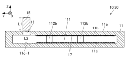
- FIG. 1 is a longitudinal cross-sectional view showing a heat dissipation board and a vapor chamber according to Embodiment 1 of the present disclosure.
- FIG. 1 is a longitudinal cross-sectional view showing a heat dissipation board and a vapor chamber according to Embodiment 1 of the present disclosure.
- FIG. 1 is a perspective view showing a heat dissipation board and a vapor chamber according to Embodiment 1 of the present disclosure.
- FIG. 3 is a vertical cross-sectional view showing the periphery of the sealed body.
- 2A is a cross-sectional view taken along line BB in FIG. 2A.
- FIG. FIG. 3 is a cross-sectional view showing a heat dissipation board of Embodiment 2.
- FIG. 3A is a cross-sectional view taken along line BB in FIG. 3A.
- FIG. FIG. 7 is a longitudinal cross-sectional view of a heat dissipation board of Embodiment 3.
- 4A is an enlarged view showing a portion C1 of FIG. 4A.
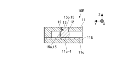
- FIG. 7 is a longitudinal cross-sectional view showing a heat dissipation board of Embodiment 4.
- FIG. 7 is a longitudinal cross-sectional view showing a heat dissipation board of Embodiment 5.
- FIG. 7 is a longitudinal cross-sectional view showing a heat dissipation board of Embodiment 6.
- FIG. 3 is a diagram illustrating the shape of the sealed body of Embodiments 1 to 3.
- FIG. 3 is a diagram illustrating the shape of the sealed body of Embodiments 1 to 3.
- FIG. 7 is a diagram illustrating the shape of the sealing body of Embodiments 4 to 6.
- FIG. 7 is a longitudinal cross-sectional view showing a heat dissipation board of Embodiment 7.
- FIG. 7 is a longitudinal cross-sectional view showing a heat dissipation board of Embodiment 8.
- 8A is an enlarged view showing part C2 of FIG. 8A.
- FIG. 3 is a longitudinal cross-sectional view showing an example in which elements are mounted on the heat dissipation board of the embodiment.
- FIG. 2 is a perspective view showing an example in which elements are mounted on the heat dissipation board of the embodiment.
- FIG. 1A and 1B are vertical cross-sectional views showing a heat dissipation board and a vapor chamber according to Embodiment 1 of the present disclosure.
- FIG. 1C is a perspective view showing a heat dissipation board and a vapor chamber according to the first embodiment.
- FIG. 1B shows the configuration before the internal space 111 is sealed.
- the heat dissipation board 10 of the first embodiment includes a housing 11 having an internal space 111 and a sealing body 15 that seals the internal space 111.
- the housing 11 may have a through hole 13 communicating with the internal space 111, an inner top surface 11b, and an inner bottom surface 11c.
- the sealing body 15 may seal the internal space 111 by blocking the through hole 13 .
- the housing 11 may have a flat plate shape (specifically, a flat plate shape in which the horizontal dimension is larger than the vertical dimension), as shown in FIG. 1C.
- the through hole 13 opens on the first surface 11a, which is the upper surface of the housing 11, and the first surface 11a may be flat.
- the internal space 111 may be a space that extends horizontally (specifically, a space whose horizontal dimension is larger than its vertical dimension).
- one or more columns 112b may be located from the inner bottom surface 11c to the inner top surface 11b.
- the support column 112b may support the housing 11 from inside the internal space 111 so that the internal space 111 does not collapse or expand.
- the housing 11 and the sealing body 15 may be made of metal.
- the main component of the metal may be copper, aluminum, titanium, nickel, stainless steel, or an iron-based alloy (for example, Kovar (FeNiCo), etc.).
- the main component means a component that accounts for 80% by mass or more.
- the metal of the housing 11 and the metal of the sealing body 15 may have the same main component.
- the metal of the housing 11 and the metal of the sealing body 15 may have the same composition.
- the term "components are the same" includes not only cases where the components are exactly the same, but also cases where the components are the same except for an error (the error is within the tolerance range).
- the material of the casing 11 described above is the material of at least the inner wall 12 of the through hole 13 (see FIG. 2), and the parts of the casing 11 other than the inner wall 12 may be made of a different material.
- the inner wall portion 12 refers to a portion of the housing 11 that surrounds the through hole 13 and faces the through hole 13, and has a thickness within the range of 1/5 to 1/2 of the diameter of the through hole 13. It may also mean a part that has.
- the heat dissipation board 10 may include a void structure 17 having voids.
- the void structure 17 may be located within the interior space 111. More specifically, the void structure 17 may be located so as to be in contact with the inner surface (for example, the inner top surface 11b, the inner bottom surface 11c, etc.) of the internal space 111, or may be integrated with the inner surface.
- the void structure 17 may be configured to act as a wick that can retain and transport the liquid phase fluid by surface tension.
- the void structure 17 may be a fibrous body, a sintered body, a porous body, or an aggregate or network structure of needle-like bodies. Alternatively, the void structure 17 may have a multilayered structure of plates having a plurality of holes (specifically, pores).
- the void structure 17 may be made of a material such as metal or ceramics.
- the vapor chamber 30 includes a heat dissipation substrate 10 and a liquid phase fluid located in an internal space 111, and the internal space 111 may be depressurized. Water, acetone, methanol, ammonia, etc. may be applied to the liquid phase fluid. With this configuration, when heat is applied to any part of the heat dissipation board 10, a phase transition (i.e., vaporization and condensation) of the liquid phase fluid occurs inside the internal space 111, and the liquid phase fluid and the liquid phase fluid are vaporized. By refluxing the gas phase fluid, the above heat can be rapidly diffused.
- a phase transition i.e., vaporization and condensation
- the vapor chamber of this embodiment can be constructed by configuring heat dissipation boards 10A to 10G of embodiments 2 to 8, which will be described later, in the same manner as described above.
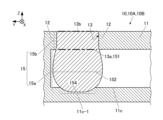
- FIG. 2A is a vertical cross-sectional view showing the periphery of the sealed body.
- FIG. 2B is a cross-sectional view taken along line BB in FIG. 2A.
- the through hole 13 may have a circular cross section, as shown in FIG. 2B.
- the sealing body 15 may have a cylindrical shape in accordance with the shape of the through hole 13.
- the through-hole 13 may have various shapes in cross section, such as an elliptical shape, an elliptical shape, a polygonal shape, a shape having linear sides and curved sides.
- the sealing body 15 may have a shape corresponding to the through hole 13.
- the opening located at the border with the internal space 111 will be referred to as a first opening 13a
- the outer opening will be referred to as a second opening 13b (see FIG. 2A).
- a portion of the housing 11 that surrounds the through hole 13 is referred to as an inner wall portion 12.
- the first opening 13a and the second opening 13b are indicated by thick dashed lines.
- the inner wall portion 12 is shown surrounded by a thick dotted line.
- the through hole 13 may be configured to extend linearly from the first opening 13a to the second opening 13b.
- the sealing body 15 may have a first portion 15a located within the internal space 111 and a second portion 15b located in the through hole 13.
- the first portion 15a may be in contact with the first inner bottom surface 11c-1 of the internal space 111.
- the first inner bottom surface 11c-1 is a part of the inner bottom surface 11c of the internal space 111, and corresponds to a portion that overlaps with the through hole 13 when seen along the through hole 13.
- the second portion 15b of the sealing body 15 may be in close contact with the inner wall portion 12 of the through hole 13 under pressure, or may be bonded with a brazing material or the like between the second portion 15b and the inner wall portion 12. It may be filled with material.
- the maximum width W15max of the first portion 15a may be larger than the minimum width W13min of the through hole 13 (ie, W15max>W13min). Furthermore, the maximum width W15max of the first portion 15a may be larger than the width W13a of the first opening 13a (ie, W15max>W13a).
- the first opening 13a means the opening located in the through hole 13 at the border with the internal space 111, as described above.
- the width W13a of the first opening 13a may mean the length of a line segment connecting from one end of the first opening 13a to the other end in the longitudinal section.
- the longitudinal section may mean a plane section passing through the center of gravity of the first opening 13a and the center of gravity of the second opening 13b.
- the above relationship between the maximum width W15max and the minimum width W13min may be a relationship that holds true in any vertical cross section, or may hold true except for vertical cross sections in some directions.
- the minimum width W13min and the maximum width W15max even if the internal pressure of the internal space 111 increases, the possibility that the sealing body 15 will come off from the through hole 13 is reduced, and the sealing state can be maintained. becomes easier. Due to the relationship between the width W13a and the maximum width W15max, even if the internal pressure of the internal space 111 increases, the risk of the sealing body 15 coming off from the through hole 13 is further reduced, and the sealing state is more easily maintained. becomes easier.
- the first portion 15a may be in contact with the first inner bottom surface 11c-1. According to this configuration, even when the internal pressure of the internal space 111 increases, the distal end surface of the first portion 15a is unlikely to be exposed to the internal pressure of the internal space 111. Therefore, it is possible to reduce the force acting on the sealing body 15 in the direction of pushing it outward due to the increased internal pressure. Therefore, the possibility that the sealing body 15 is displaced in the direction of coming out of the through hole 13 is reduced, and it becomes easier to maintain the sealed state of the internal space 111.
- the rigidity of the portion of the housing 11 near the sealing body 15 is increased. Therefore, when performing ultrasonic bonding of the terminals or conductive wires of the element to the first surface 11a, the bonding becomes easy.
- the length L1 of the sealed body 15 before sealing is from the outer opening of the through hole 13 (specifically, the second opening 13b, see FIG. 2A) to the first inner bottom surface. It may be longer than the length L2 up to 11c-1.
- the sealed body 15 before sealing may have a thickness that allows it to pass through the through hole 13.
- the sealing process may include a step of passing the sealing body 15 through the through hole 13 until one end of the sealing body 15 contacts the first inner bottom surface 11c-1, and a step of further pushing the sealing body 15. good.
- the first portion 15a of the sealing body 15 is deformed to expand in diameter, and the maximum width W15max of the first portion 15a becomes larger than the minimum width W13min of the through hole 13. .
- the second portion 15b of the sealing body 15 expands in diameter, or the periphery of the second portion 15b is filled with a bonding material such as a brazing material, so that the through hole 13 is expanded.
- the internal space 111 is sealed.
- the sealing body 15 may be cut or polished before or after passing through the through hole 13 so that the first surface 11a and the end surface of the sealing body 15 are flush with each other.
- a liquid phase fluid may be injected into the internal space 111 through the through hole 13. Furthermore, the above sealing step may be performed in a reduced pressure space. Through this process, the internal space 111 can be sealed in a state where the internal space 111 contains the liquid phase fluid and is under reduced pressure.
- the sealing structure of the heat dissipating substrate 10 achieved by the above-described sealing process, deformation hardly occurs in the through-holes 13, especially around the first surface 11a side of the through-holes 13, and therefore, even around the sealing part.
- the flatness of the first surface 11a can be improved.
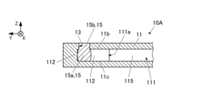
- FIG. 3A is a cross-sectional view showing the heat dissipation board of Embodiment 2.
- FIG. 3B is a cross-sectional view taken along line BB in FIG. 3A.
- the heat dissipation board 10A of the second embodiment may be the same as that of the first embodiment except that the structure near the sealing body 15 in the internal space 111 is different.
- the support body 112 of the internal space 111 may be located on the side of the sealing body 15.
- the support body 112 is a structure that supports the casing 11 from inside the interior space 111 to prevent the interior space 111 from collapsing or expanding. It may also be a pillar located over the top surface 11b.
- a side wall that is thicker than the other portions is applied as a support 112.
- the support body 112 may be located so as to be in contact with the first portion 15a of the sealing body 15.
- the support body 112 and the sealing body 15 may be in contact with each other entirely from the inner bottom surface 11c to the inner top surface 11b, or only a part thereof may be in contact with each other, or there may be a slight gap between them. .
- the supports 112 may be located on three sides in the horizontal direction when viewed from the sealing body 15, or may be located on two or one side in the horizontal direction.
- two directions and “three directions” refer to one to three directions obtained by dividing the entire circumference into four equal parts in the horizontal direction.
- the support body 112 located on the side of the sealing body 15 may be thicker than the side wall 115 in other areas.
- the presence of the support body 112 can further reduce deformation of the periphery of the through hole 13 when the through hole 13 is closed with the sealing body 15. Furthermore, by making the support body 112 thick, the above deformation can be further reduced. Further, by making the support body 112 thick, the through holes 13 can be arranged so as not to be too close to the end of the first surface 11a, and there is an advantage that the degree of freedom in the arrangement of the through holes 13 can be increased at the design stage. arise.
- a passage 111a that connects to a wide portion of the internal space 111 is located on the remaining one.
- the width W111 of the passage 111a may be larger than, the same as, or smaller than the diameter ⁇ 13 of the through hole 13. The smaller the size, the more effective the effect of reducing deformation of the casing 11 near the sealing part can be obtained.
- the diameter may be referred to as the minimum width. Since circulation of the liquid phase fluid is difficult to occur in the passage 111a, the passage 111a may be located at a portion where the heat dissipation effect may be reduced (for example, near the outer periphery of the first surface 11a in plan view).
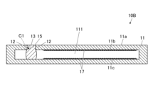
- FIG. 4A is a longitudinal cross-sectional view of the heat dissipation board of Embodiment 3.
- FIG. 4B is an enlarged view of portion C1 in FIG. 4A.
- the heat dissipation substrate 10B of the third embodiment is similar to the components of the first and second embodiments except for the crystal grain size of the inner wall portion 12 of the through hole 13 and the crystal grain size of the sealing body 15. good.
- the crystal grain size ⁇ 1 of the sealing body 15 and the crystal grain size ⁇ 2 of the inner wall portion 12 may satisfy the following condition (1). That is, the crystal grain size ⁇ 1 of the sealing body 15 may be equal to or larger than the crystal grain size ⁇ 2 of the inner wall portion 12. ⁇ 1 > 0.8 ⁇ 2 ... (1)
- sealing body 15 and the inner wall portion 12 may have the same metal as the main component, or may have the same metal (for example, copper).
- the crystal grain sizes ⁇ 1 and ⁇ 2 may satisfy the condition (2) below, or may further satisfy the condition (3) below. ⁇ 1 ⁇ ⁇ 2 ...(2) ⁇ 1 > ⁇ 2 ... (3)
- the larger the crystal grain size the easier it is to deform when stress is applied. Therefore, by satisfying the condition (1) above, when closing the through hole 13 with the sealing body 15, the sealing body 15 can be deformed while further reducing deformation around the through hole 13 of the housing 11. Therefore, the flatness around the sealing portion on the outer surface side of the housing 11 can be further improved. Furthermore, by satisfying the conditions (2) and (3) above, the above effects can be better obtained, and the flatness around the sealing portion can be further improved.
- the above crystal grain size means the average value of crystal grain sizes, and can be measured as follows. That is, a cross-sectional photograph of the relevant portion is prepared, a line segment of a predetermined length is drawn on the cross-sectional photograph, and the crystal grains that overlap with the line segment are counted. The number of crystal grains that overlap the ends of the line segment is 1/2. Then, by dividing the length of the line segment (specifically, the length obtained by dividing the magnification of the cross-sectional photograph) by the number of counted crystal grains, the crystal grain size of a set of samples is obtained. Furthermore, the crystal grain sizes of a plurality of sets of samples are calculated by changing the direction and position of the line segment, and the average value of the calculated values is taken as the crystal grain size of the measurement target.
- the crystal grain size of the inner wall portion 12 and the crystal grain size of the sealing body 15 can be adjusted to be large or small by applying heat treatment. Therefore, the above (1) to (3) can be achieved by subjecting the sealed body 15 to heat treatment that is equivalent to the heat treatment applied in the manufacturing process of the casing 11 before sealing, or with a predetermined difference added to the heat treatment.
- a sealed body 15 having a crystal grain size that satisfies the conditions can be manufactured.
- the casing 11 may have substantially the same crystal grain size in the inner wall portion 12 and other arbitrary locations.
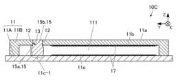
- FIG. 4 is vertical cross-sectional views showing the heat dissipation substrates of Embodiment 4, Embodiment 5, and Embodiment 6, respectively.
- the heat dissipation substrates 10C to 10E of the fourth to sixth embodiments are the same as those of the first to third embodiments except that the characteristics of the first inner bottom surface 11c-1 of the internal space 111 with which the first portion 15a of the sealing body 15 contacts are different. It may be.
- the Young's modulus of the first inner bottom surface 11c-1 may be larger than the Young's modulus of the sealing body 15. Further, the Young's modulus of the first inner bottom surface 11c-1 may be larger than the Young's modulus of the inner wall portion 12 of the through hole 13.
- the first inner bottom surface 11c-1 refers to a portion of the inner bottom surface 11c of the internal space 111 that is in contact with the first portion 15a of the sealing body 15. Young's modulus may mean a value measured by the nanoindentation method specified in the international standard ISO14577.
- the first portion 15a of the sealing body 15 when closing the through hole 13 with the sealing body 15, the first portion 15a of the sealing body 15 can be efficiently deformed to swell in the horizontal direction. Therefore, the first portion 15a of the sealing body 15 can be pushed and expanded with less energy than when the Young's modulus of the first inner bottom surface 11c-1 is not large. Therefore, the energy applied from the sealing body 15 to the through hole 13 can also be reduced, and deformation around the through hole 13 can be reduced. Therefore, the flatness around the sealing portion on the outer surface side of the housing 11 can be further improved.
- the heat dissipating substrates 10C to 10E of embodiments 4 to 6 may be configured as follows. That is, in the heat dissipation board 10C of the fourth embodiment in FIG. 5A, the housing 11 may include a base 11A and an upper structure 11B joined to the base 11A.
- the base portion 11A may be made of a material different from that of the sealing body 15.
- the upper structure 11B and the sealing body 15 may be made of metal such as copper, and the base 11A may be made of ceramic.
- a material containing silicon nitride (Si 3 N 4 ), silicon carbide (SiC), mullite, aluminum nitride (AlN), aluminum oxide (Al 2 O 3 ), etc. as a main component may be applied to the ceramic. .
- the base 11A and the upper structure 11B may be joined via a joining material such as a brazing material.
- the internal space 111 may be located between the base 11A and the upper structure 11B, and the through hole 13 may be located in the upper structure 11B.
- the upper surface of the base portion 11A may include a first inner bottom surface 11c-1.
- the heat dissipation board 10D of the fifth embodiment in FIG. 5B may have a plate-like or film-like member 11D made of a different material from other parts of the casing 11 at a portion overlapping with the first inner bottom surface 11c-1.
- the member 11D may be made of ceramic and bonded to the inner bottom surface 11c of the housing 11 via a bonding material such as a brazing material.
- the ceramic may include silicon nitride (Si 3 N 4 ), silicon carbide (SiC), mullite, aluminum nitride (AlN), aluminum oxide (Al 2 O 3 ), or the like as a main component.
- the bottom of the casing 11 has a multilayer structure, and the top layer 11E of the bottom (that is, the layer exposed as the inner bottom surface 11c) is different from other parts of the casing 11. It may be made of any material.
- the top layer 11E may be made of ceramic.
- the ceramic may include silicon nitride (Si 3 N 4 ), silicon carbide (SiC), mullite, aluminum nitride (AlN), aluminum oxide (Al 2 O 3 ), or the like as a main component.
- the configuration of the heat dissipation substrates 10C to 10E of the fourth to sixth embodiments described above makes it possible to realize the above Young's modulus relationship.
- FIG. 6A is a diagram illustrating the shape of the sealing body of Embodiments 1 to 3.
- FIG. 6B is a diagram illustrating the shape of the sealing body of Embodiments 4 to 6.
- the Young's modulus of the first inner bottom surface 11c-1 and the Young's modulus of the sealing body 15 and the inner wall portion 12 are equivalent.
- the Young's modulus of the first inner bottom surface 11c-1 is larger than the Young's modulus of the sealing body 15 and the inner wall portion 12.
- the opening located at the border with the internal space 111 is called the first opening 13a
- the outer opening is called the second opening 13b.
- the first portion 15a of the sealing body 15 has an upper end portion 151 located at the first opening 13a of the through hole 13 and a first inner bottom surface 11c-1. It includes a lower end portion 154 that contacts, and a first intermediate portion 152 located between the upper end portion 151 and the lower end portion 154.
- the outline of the first portion 15a in the longitudinal section has a gentle curve in which the width gradually increases from the upper end portion 151 to the first intermediate portion 152, and the width gradually decreases from the first intermediate portion 152 downward. Good too. If the sealing body 15 has a cylindrical shape, the above width may be referred to as the diameter.
- the first inner bottom surface 11c-1 may have a concave shape, and the tip of the first portion 15a may fit into the concave.
- the bulge appearing in the outline of the first portion 15a and the depression in the first inner bottom surface 11c-1 are formed by the sealing body 15 being pushed downward when the sealing body 15 closes the through hole 13. It may also have a different shape.
- the first portion 15a of the sealing body 15 has an upper end portion 151, a lower end portion 154, and a first intermediate portion 152, as in Embodiments 1 to 3. You can. Furthermore, similarly to Embodiments 1 to 3, the width of the outline of the first portion 15a in the longitudinal section gradually increases from the upper end portion 151 to the first intermediate portion 152, and the width gradually decreases from the first intermediate portion downward. It may have a gentle curve. If the sealing body 15 has a cylindrical shape, the above width may be referred to as the diameter.
- first portion 15a of embodiments 4 to 6 has a second intermediate portion 153 between the first intermediate portion 152 and the lower end portion 154, and the outline of the first portion 15a in the longitudinal section is the same as the first portion 15a.
- the two intermediate portions 153 may include a bend 153a with a minimum width.
- the second intermediate portion 153 having the smallest width may be called a constriction.
- the first inner bottom surface 11c-1 is planar, and the first portion 15a of the sealing body 15 has a width that gradually increases from the second intermediate portion 153 to the lower end portion 154. You can.
- the bulge that appears in the outline of the first portion 15a and the bend (that is, the shape of the constriction) of the second intermediate portion 153 are formed by pressure being applied to the sealing body 15 when the sealing body 15 closes the through hole 13. This is caused by the large Young's modulus of the first inner bottom surface 11c-1.
- the shape of the sealing body 15 shown in FIGS. 6A and 6B allows the inner space 111 to be sealed by blocking the through hole 13 while reducing deformation of the periphery of the second opening 13b of the through hole 13. Can be done. Furthermore, even when the internal pressure of the internal space 111 changes in level, the sealing of the internal space 111 can be easily maintained.
- FIG. 7 is a longitudinal cross-sectional view showing a heat dissipation board of Embodiment 7.
- the heat dissipation board 10F of the seventh embodiment may be the same as those of the first to sixth embodiments, except that the configuration regarding the gap structure 17 is different.
- FIG. 7 shows an example in which the bottom of the casing 11 is made of a different material from other parts, the entire casing 11 may be made of the same material.
- the void structure 17 may be integrated with the inner bottom surface 11c of the housing 11, and may be a part of the inner bottom surface 11c.
- the inner bottom surface 11c includes a first inner bottom surface 11c-1 that is in contact with the first portion 15a of the sealing body 15, and a second inner bottom surface 11c-2 that is adjacent to the first inner bottom surface 11c-1.
- 17 may include a first void structure 17-1 located on the first inner bottom surface 11c-1 and a second void structure 17-2 located on the second inner bottom surface 11c-2.
- the second inner bottom surface 11c-2 may mean a portion of the inner bottom surface 11c around the first inner bottom surface 11c-1.
- the sealing body 15 By positioning the first cavity structure 17-1 on the first inner bottom surface 11c-1, after the tip of the sealing body 15 hits the first inner bottom surface 11c-1 in the sealing process, the sealing body When pushing in the sealing body 15, a frictional force acts on the tip of the sealing body 15. Therefore, it is possible to reduce the possibility that the tip of the sealing body 15 will slip on the first inner bottom surface 11c-1 and causing an unexpected bend in the sealing body 15. Therefore, the sealing process can be performed more stably, and the yield of the heat dissipation substrate 10F can be improved.
- the porosity of the first void structure 17-1 may be smaller than the porosity of the second void structure 17-2.
- the porosity refers to the volume occupied by voids per unit volume of the void structure 17. This difference in porosity means that the degree of bonding between the tip of the sealing body 15 and the first inner bottom surface 11c-1 is improved by the first void structure 17-1. Therefore, with the above configuration, the anchor effect by the first cavity structure 17-1 can be obtained, and the displacement of the sealing body 15 in the direction of coming out of the through hole 13 can be further reduced.
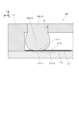
- FIG. 8A is a longitudinal cross-sectional view showing a heat dissipation board of Embodiment 8.
- FIG. 8B is an enlarged view showing portion C2 of FIG. 8A.
- the heat dissipation board 10G of the eighth embodiment may be the same as those of the first to seventh embodiments, except that a portion of the inner wall portion 12 surrounding the through hole 13 is different.
- the inner wall portion 12 surrounding the through hole 13 may include a protrusion portion 12a that protrudes toward the internal space 111 side.
- the protruding portion 12a may be in contact with the sealing body 15.
- the protrusion 12a is located at the boundary between the through hole 13 and the internal space 111 (ie, the first opening 13a), and the tip of the protrusion 12a may have an acute angle.
- the term "the tip of the protrusion 12a has an acute angle” means that the corner of the tip of the protrusion 12a has an acute angle in a longitudinal section.
- the acute angle means an acute angle when microscopic roundness is ignored. That is, as shown in FIG.
- an acute angle means that the angle ⁇ formed by the extension line of the first side 12a-1 and the extension line of the second side 12a-2 that are adjacent to each other with the tip of the protrusion 12a sandwiched therebetween is an acute angle. It may also mean that
- the protrusion 12a can be formed as follows. That is, when forming the through hole 13 in the housing 11, burrs are left in the opening on the internal space 111 side (ie, the first opening 13a). Then, the burr is tilted so that the end of the burr faces the center of the opening. In this state, by performing a sealing process using the sealant 15, the protrusion 12a can be formed.
- the first opening 13a of the through hole 13 becomes difficult to expand even when the internal pressure of the internal space 111 increases. Therefore, the possibility that the sealing body 15 is displaced outward in the through hole 13 can be further reduced, and the airtightness between the inner wall portion 12 of the through hole 13 and the sealing body 15 can be further improved.
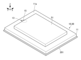
- Example of mounting elements 9A and 9B are a longitudinal cross-sectional view and a perspective view showing an example in which elements are mounted on a heat dissipation board according to an embodiment.
- the heat dissipation board 10 and the vapor chamber 30 of the first embodiment are mounted with the heat generating element 51 and dissipate the heat of the element 51.
- the element 51 may be a power element that allows a large current to flow, such as a power semiconductor, or may be various other elements.
- the element 51 may be mounted on the module substrate 201 via the heat dissipation substrate 10 and the vapor chamber 30.
- the element 51 may be mounted so as to overlap the area where the through hole 13 and the sealing body 15 of the first surface 11a are located, or may be mounted outside the area. Good too.
- the terminal of the element 51 may be joined to the above region of the first surface 11a.
- the terminals may be bonded via a conductive bonding material, or may be bonded by ultrasonic bonding or the like.
- the flatness around the sealing portion on the outer surface of the housing 11 can be improved. Therefore, even when mounting the element 51 on the first surface 11a as shown in FIGS. 9A and 9B, it is possible to reduce the possibility that the sealing portion becomes an obstacle to mounting the element 51.
- the heat dissipating board 10 and vapor of the first embodiment are The chamber 30 can have high lateral flatness as well. Therefore, when a plurality of heat dissipation boards 10 and vapor chambers 30 are mounted side by side on one module board 201, adjacent heat dissipation boards 10 and vapor chambers 30 can be mounted close together. can improve the aggregation of Furthermore, the degree of freedom in arranging the heat dissipation board 10 and the vapor chamber 30 can be improved.
- the heat dissipation board 10 of FIGS. 9A and 9B may be replaced with the heat dissipation boards 10A to 10G of Embodiments 2 to 8, and the replaced configuration can also provide the same effect as described above.
- the heat dissipation board is a casing having an internal space; a sealing body that seals the internal space; Equipped with The casing has a through hole connected to the internal space and an inner bottom surface, The sealing body has a first part located in the internal space and a second part located in the through hole, the first portion contacts the inner bottom surface; In the longitudinal section, the maximum width of the first portion is larger than the minimum width of the through hole.
- the heat dissipation board of (1) above is The through hole includes a first opening located at a border with the internal space, In the longitudinal section, the maximum width of the first portion is larger than the width of the first opening.
- the heat dissipation board of (1) or (2) above is The casing has a planar first surface, One end of the through hole is located on the first surface.
- the heat dissipation board according to any one of (1) to (3) above,
- the casing has an inner wall portion surrounding the through hole,
- the crystal grain size of the sealed body is ⁇ 1
- the crystal grain size of the inner wall portion is ⁇ 2, ⁇ 1 > 0.8 ⁇ ⁇ 2 It is.
- the heat dissipation board of (4) above is The inner wall portion and the sealing body are made of the same metal as a main component.
- the inner bottom surface includes a first inner bottom surface with which the sealing body contacts,
- the casing has an inner wall portion surrounding the through hole,
- the Young's modulus of the first inner bottom surface is higher than the Young's modulus of the sealed body,
- the Young's modulus of the first inner bottom surface is higher than the Young's modulus of the inner wall portion.
- the heat dissipation board according to any one of (1) to (6) above, further comprising a void structure having voids;
- the void structure is located on the inner bottom surface,
- the inner bottom surface includes a first inner bottom surface with which the sealing body contacts and a second inner bottom surface adjacent to the first inner bottom surface,
- the void structure includes a first void structure located on the first inner bottom surface and a second void structure located on the second inner bottom surface,
- the porosity of the first void structure is smaller than the porosity of the second void structure.
- the heat dissipation board according to any one of (1) to (7) above,
- the casing has an inner wall portion surrounding the through hole,
- the inner wall portion includes a protrusion located on the inner space side,
- the protrusion is in contact with the sealing body.
- the heat dissipation board according to any one of (1) to (8) above,
- the through hole includes a first opening located at a border with the internal space
- the first portion of the sealing body includes an upper end portion located at the first opening, a lower end portion in contact with the inner bottom surface, and a first intermediate portion located between the upper end portion and the lower end portion.
- has The outline of the first portion in a longitudinal section is such that the width of the first portion gradually increases from the upper end portion to the first intermediate portion, and the width of the first portion gradually decreases from the first intermediate portion downward. Contains a curve.
- the heat dissipation board of (9) above is The first portion of the sealing body has a second intermediate portion between the first intermediate portion and the lower end portion, The outline of the first portion in the longitudinal section includes a bend where the width of the first portion becomes minimum at the second intermediate portion.
- the vapor chamber is The heat dissipation board according to any one of (1) to (10), a liquid phase fluid located in the internal space; Equipped with.
- the present disclosure can be used for heat dissipation substrates and vapor chambers.
Landscapes
- Engineering & Computer Science (AREA)
- Physics & Mathematics (AREA)
- Thermal Sciences (AREA)
- Mechanical Engineering (AREA)
- General Engineering & Computer Science (AREA)
- Microelectronics & Electronic Packaging (AREA)
- Life Sciences & Earth Sciences (AREA)
- Sustainable Development (AREA)
- Cooling Or The Like Of Semiconductors Or Solid State Devices (AREA)
Priority Applications (3)
| Application Number | Priority Date | Filing Date | Title |
|---|---|---|---|
| EP23843031.8A EP4560243A1 (en) | 2022-07-22 | 2023-07-20 | Heat-emitting substrate and vapor chamber |
| CN202380054489.8A CN119604736A (zh) | 2022-07-22 | 2023-07-20 | 散热基板及均热板 |
| JP2024535126A JPWO2024019108A1 (https=) | 2022-07-22 | 2023-07-20 |
Applications Claiming Priority (2)
| Application Number | Priority Date | Filing Date | Title |
|---|---|---|---|
| JP2022-117281 | 2022-07-22 | ||
| JP2022117281 | 2022-07-22 |
Publications (1)
| Publication Number | Publication Date |
|---|---|
| WO2024019108A1 true WO2024019108A1 (ja) | 2024-01-25 |
Family
ID=89617877
Family Applications (1)
| Application Number | Title | Priority Date | Filing Date |
|---|---|---|---|
| PCT/JP2023/026555 Ceased WO2024019108A1 (ja) | 2022-07-22 | 2023-07-20 | 放熱基板及びベイパーチャンバー |
Country Status (4)
| Country | Link |
|---|---|
| EP (1) | EP4560243A1 (https=) |
| JP (1) | JPWO2024019108A1 (https=) |
| CN (1) | CN119604736A (https=) |
| WO (1) | WO2024019108A1 (https=) |
Cited By (1)
| Publication number | Priority date | Publication date | Assignee | Title |
|---|---|---|---|---|
| WO2025244034A1 (ja) * | 2024-05-21 | 2025-11-27 | 京セラ株式会社 | 放熱部材、ベイパーチャンバー及び機能モジュール |
Citations (7)
| Publication number | Priority date | Publication date | Assignee | Title |
|---|---|---|---|---|
| JPS53106961A (en) * | 1977-02-28 | 1978-09-18 | Ngk Spark Plug Co Ltd | Ceramic heating pipes and manufacturing method |
| JPS5885555A (ja) * | 1981-11-17 | 1983-05-21 | Ngk Spark Plug Co Ltd | セラミツクヒ−トシンク |
| JPH0321679U (https=) * | 1989-06-29 | 1991-03-05 | ||
| JP2007315745A (ja) * | 2005-09-01 | 2007-12-06 | Fuchigami Micro:Kk | ヒートパイプ及びその製造方法 |
| JP4035155B1 (ja) * | 2006-07-28 | 2008-01-16 | 株式会社渕上ミクロ | ヒートパイプ及びその製造方法 |
| CN106225533A (zh) * | 2016-07-29 | 2016-12-14 | 苏州聚力电机有限公司 | 均温板的封口方法 |
| WO2021182644A1 (ja) * | 2020-03-13 | 2021-09-16 | 古河電気工業株式会社 | ベーパチャンバおよびベーパチャンバの製造方法 |
-
2023
- 2023-07-20 EP EP23843031.8A patent/EP4560243A1/en active Pending
- 2023-07-20 CN CN202380054489.8A patent/CN119604736A/zh active Pending
- 2023-07-20 WO PCT/JP2023/026555 patent/WO2024019108A1/ja not_active Ceased
- 2023-07-20 JP JP2024535126A patent/JPWO2024019108A1/ja active Pending
Patent Citations (8)
| Publication number | Priority date | Publication date | Assignee | Title |
|---|---|---|---|---|
| JPS53106961A (en) * | 1977-02-28 | 1978-09-18 | Ngk Spark Plug Co Ltd | Ceramic heating pipes and manufacturing method |
| JPS5885555A (ja) * | 1981-11-17 | 1983-05-21 | Ngk Spark Plug Co Ltd | セラミツクヒ−トシンク |
| JPH0321679U (https=) * | 1989-06-29 | 1991-03-05 | ||
| JP2007315745A (ja) * | 2005-09-01 | 2007-12-06 | Fuchigami Micro:Kk | ヒートパイプ及びその製造方法 |
| JP4035155B1 (ja) * | 2006-07-28 | 2008-01-16 | 株式会社渕上ミクロ | ヒートパイプ及びその製造方法 |
| WO2008012960A1 (fr) | 2006-07-28 | 2008-01-31 | Molex Kiire Co., Ltd. | tuyau chauffant et son procédé de fabrication |
| CN106225533A (zh) * | 2016-07-29 | 2016-12-14 | 苏州聚力电机有限公司 | 均温板的封口方法 |
| WO2021182644A1 (ja) * | 2020-03-13 | 2021-09-16 | 古河電気工業株式会社 | ベーパチャンバおよびベーパチャンバの製造方法 |
Cited By (1)
| Publication number | Priority date | Publication date | Assignee | Title |
|---|---|---|---|---|
| WO2025244034A1 (ja) * | 2024-05-21 | 2025-11-27 | 京セラ株式会社 | 放熱部材、ベイパーチャンバー及び機能モジュール |
Also Published As
| Publication number | Publication date |
|---|---|
| JPWO2024019108A1 (https=) | 2024-01-25 |
| CN119604736A (zh) | 2025-03-11 |
| EP4560243A1 (en) | 2025-05-28 |
Similar Documents
| Publication | Publication Date | Title |
|---|---|---|
| CN107532860B (zh) | 高性能两相冷却设备 | |
| CN113639574A (zh) | 用于便携式应用的高性能两相冷却装置 | |
| CN110869689B (zh) | 吸液芯结构体及收纳有吸液芯结构体的热管 | |
| WO2018198354A1 (ja) | ベーパーチャンバー | |
| JP2018503058A5 (https=) | ||
| WO2018199215A1 (ja) | ベーパーチャンバー | |
| CN218583848U (zh) | 均热板以及电子设备 | |
| CN112771344B (zh) | 均热板 | |
| WO2024019108A1 (ja) | 放熱基板及びベイパーチャンバー | |
| JP7647922B2 (ja) | 熱拡散デバイス | |
| US20240401885A1 (en) | Vapor chamber | |
| CN115954252A (zh) | 晶片载放台 | |
| TWI867402B (zh) | 熱擴散裝置及電子機器 | |
| WO2018198350A1 (ja) | ベーパーチャンバー | |
| JP2021158190A (ja) | 電子機器及びベーパーチャンバー | |
| WO2026061333A1 (zh) | 一种微型集成式压电泵装置 | |
| KR20190116092A (ko) | 세라믹스 구조체 | |
| TWI894536B (zh) | 封裝體 | |
| WO2023190524A1 (ja) | 放熱板及びベイパーチャンバー | |
| JP2011009808A (ja) | 水晶振動子 | |
| JP7630238B2 (ja) | 保持装置 | |
| JP2002093931A (ja) | 高周波用セラミックパッケージ | |
| JP5004837B2 (ja) | 構造体及び電子装置 | |
| CN113396535A (zh) | 试样保持工具 | |
| JP7774113B1 (ja) | 保持装置 |
Legal Events
| Date | Code | Title | Description |
|---|---|---|---|
| 121 | Ep: the epo has been informed by wipo that ep was designated in this application |
Ref document number: 23843031 Country of ref document: EP Kind code of ref document: A1 |
|
| WWE | Wipo information: entry into national phase |
Ref document number: 2024535126 Country of ref document: JP |
|
| WWE | Wipo information: entry into national phase |
Ref document number: 202380054489.8 Country of ref document: CN |
|
| WWE | Wipo information: entry into national phase |
Ref document number: 2023843031 Country of ref document: EP |
|
| NENP | Non-entry into the national phase |
Ref country code: DE |
|
| ENP | Entry into the national phase |
Ref document number: 2023843031 Country of ref document: EP Effective date: 20250224 |
|
| WWP | Wipo information: published in national office |
Ref document number: 202380054489.8 Country of ref document: CN |
|
| WWP | Wipo information: published in national office |
Ref document number: 2023843031 Country of ref document: EP |