WO2024019108A1 - Heat-emitting substrate and vapor chamber - Google Patents
Heat-emitting substrate and vapor chamber Download PDFInfo
- Publication number
- WO2024019108A1 WO2024019108A1 PCT/JP2023/026555 JP2023026555W WO2024019108A1 WO 2024019108 A1 WO2024019108 A1 WO 2024019108A1 JP 2023026555 W JP2023026555 W JP 2023026555W WO 2024019108 A1 WO2024019108 A1 WO 2024019108A1
- Authority
- WO
- WIPO (PCT)
- Prior art keywords
- inner bottom
- heat dissipation
- hole
- sealing body
- internal space
- Prior art date
Links
- 239000000758 substrate Substances 0.000 title abstract description 18
- 238000007789 sealing Methods 0.000 claims abstract description 119
- 230000017525 heat dissipation Effects 0.000 claims description 75
- 239000011800 void material Substances 0.000 claims description 28
- 239000013078 crystal Substances 0.000 claims description 24
- 239000012530 fluid Substances 0.000 claims description 15
- 229910052751 metal Inorganic materials 0.000 claims description 15
- 239000002184 metal Substances 0.000 claims description 15
- 239000007791 liquid phase Substances 0.000 claims description 14
- 230000007423 decrease Effects 0.000 claims description 4
- 239000000463 material Substances 0.000 description 19
- 238000000034 method Methods 0.000 description 9
- 230000001154 acute effect Effects 0.000 description 7
- 239000000919 ceramic Substances 0.000 description 7
- 230000000694 effects Effects 0.000 description 5
- RYGMFSIKBFXOCR-UHFFFAOYSA-N Copper Chemical compound [Cu] RYGMFSIKBFXOCR-UHFFFAOYSA-N 0.000 description 4
- 238000005219 brazing Methods 0.000 description 4
- 229910052802 copper Inorganic materials 0.000 description 4
- 239000010949 copper Substances 0.000 description 4
- 238000010586 diagram Methods 0.000 description 4
- 238000010438 heat treatment Methods 0.000 description 4
- CSCPPACGZOOCGX-UHFFFAOYSA-N Acetone Chemical compound CC(C)=O CSCPPACGZOOCGX-UHFFFAOYSA-N 0.000 description 3
- 229910018072 Al 2 O 3 Inorganic materials 0.000 description 3
- PIGFYZPCRLYGLF-UHFFFAOYSA-N Aluminum nitride Chemical compound [Al]#N PIGFYZPCRLYGLF-UHFFFAOYSA-N 0.000 description 3
- OKKJLVBELUTLKV-UHFFFAOYSA-N Methanol Chemical compound OC OKKJLVBELUTLKV-UHFFFAOYSA-N 0.000 description 3
- 229910052581 Si3N4 Inorganic materials 0.000 description 3
- KZHJGOXRZJKJNY-UHFFFAOYSA-N dioxosilane;oxo(oxoalumanyloxy)alumane Chemical compound O=[Si]=O.O=[Si]=O.O=[Al]O[Al]=O.O=[Al]O[Al]=O.O=[Al]O[Al]=O KZHJGOXRZJKJNY-UHFFFAOYSA-N 0.000 description 3
- 229910052863 mullite Inorganic materials 0.000 description 3
- TWNQGVIAIRXVLR-UHFFFAOYSA-N oxo(oxoalumanyloxy)alumane Chemical compound O=[Al]O[Al]=O TWNQGVIAIRXVLR-UHFFFAOYSA-N 0.000 description 3
- HBMJWWWQQXIZIP-UHFFFAOYSA-N silicon carbide Chemical compound [Si+]#[C-] HBMJWWWQQXIZIP-UHFFFAOYSA-N 0.000 description 3
- HQVNEWCFYHHQES-UHFFFAOYSA-N silicon nitride Chemical compound N12[Si]34N5[Si]62N3[Si]51N64 HQVNEWCFYHHQES-UHFFFAOYSA-N 0.000 description 3
- QGZKDVFQNNGYKY-UHFFFAOYSA-N Ammonia Chemical compound N QGZKDVFQNNGYKY-UHFFFAOYSA-N 0.000 description 2
- XEEYBQQBJWHFJM-UHFFFAOYSA-N Iron Chemical compound [Fe] XEEYBQQBJWHFJM-UHFFFAOYSA-N 0.000 description 2
- PXHVJJICTQNCMI-UHFFFAOYSA-N Nickel Chemical compound [Ni] PXHVJJICTQNCMI-UHFFFAOYSA-N 0.000 description 2
- 230000000903 blocking effect Effects 0.000 description 2
- 230000005484 gravity Effects 0.000 description 2
- 150000002739 metals Chemical class 0.000 description 2
- 239000012071 phase Substances 0.000 description 2
- RTAQQCXQSZGOHL-UHFFFAOYSA-N Titanium Chemical compound [Ti] RTAQQCXQSZGOHL-UHFFFAOYSA-N 0.000 description 1
- 238000004220 aggregation Methods 0.000 description 1
- 230000002776 aggregation Effects 0.000 description 1
- 229910045601 alloy Inorganic materials 0.000 description 1
- 239000000956 alloy Substances 0.000 description 1
- 229910052782 aluminium Inorganic materials 0.000 description 1
- XAGFODPZIPBFFR-UHFFFAOYSA-N aluminium Chemical compound [Al] XAGFODPZIPBFFR-UHFFFAOYSA-N 0.000 description 1
- 229910021529 ammonia Inorganic materials 0.000 description 1
- 238000009833 condensation Methods 0.000 description 1
- 230000005494 condensation Effects 0.000 description 1
- 238000006073 displacement reaction Methods 0.000 description 1
- 238000002347 injection Methods 0.000 description 1
- 239000007924 injection Substances 0.000 description 1
- 229910052742 iron Inorganic materials 0.000 description 1
- 229910000833 kovar Inorganic materials 0.000 description 1
- 238000004519 manufacturing process Methods 0.000 description 1
- 238000005259 measurement Methods 0.000 description 1
- 239000000203 mixture Substances 0.000 description 1
- 229910052759 nickel Inorganic materials 0.000 description 1
- 230000035515 penetration Effects 0.000 description 1
- 239000011148 porous material Substances 0.000 description 1
- 238000010992 reflux Methods 0.000 description 1
- 239000003507 refrigerant Substances 0.000 description 1
- 239000000565 sealant Substances 0.000 description 1
- 239000004065 semiconductor Substances 0.000 description 1
- 239000010935 stainless steel Substances 0.000 description 1
- 229910001220 stainless steel Inorganic materials 0.000 description 1
- 239000010936 titanium Substances 0.000 description 1
- 229910052719 titanium Inorganic materials 0.000 description 1
- 230000007704 transition Effects 0.000 description 1
- 238000009834 vaporization Methods 0.000 description 1
- 230000008016 vaporization Effects 0.000 description 1
- XLYOFNOQVPJJNP-UHFFFAOYSA-N water Substances O XLYOFNOQVPJJNP-UHFFFAOYSA-N 0.000 description 1
Images


Classifications
-
- B—PERFORMING OPERATIONS; TRANSPORTING
- B21—MECHANICAL METAL-WORKING WITHOUT ESSENTIALLY REMOVING MATERIAL; PUNCHING METAL
- B21D—WORKING OR PROCESSING OF SHEET METAL OR METAL TUBES, RODS OR PROFILES WITHOUT ESSENTIALLY REMOVING MATERIAL; PUNCHING METAL
- B21D39/00—Application of procedures in order to connect objects or parts, e.g. coating with sheet metal otherwise than by plating; Tube expanders
-
- F—MECHANICAL ENGINEERING; LIGHTING; HEATING; WEAPONS; BLASTING
- F28—HEAT EXCHANGE IN GENERAL
- F28D—HEAT-EXCHANGE APPARATUS, NOT PROVIDED FOR IN ANOTHER SUBCLASS, IN WHICH THE HEAT-EXCHANGE MEDIA DO NOT COME INTO DIRECT CONTACT
- F28D15/00—Heat-exchange apparatus with the intermediate heat-transfer medium in closed tubes passing into or through the conduit walls ; Heat-exchange apparatus employing intermediate heat-transfer medium or bodies
- F28D15/02—Heat-exchange apparatus with the intermediate heat-transfer medium in closed tubes passing into or through the conduit walls ; Heat-exchange apparatus employing intermediate heat-transfer medium or bodies in which the medium condenses and evaporates, e.g. heat pipes
-
- H—ELECTRICITY
- H01—ELECTRIC ELEMENTS
- H01L—SEMICONDUCTOR DEVICES NOT COVERED BY CLASS H10
- H01L23/00—Details of semiconductor or other solid state devices
- H01L23/34—Arrangements for cooling, heating, ventilating or temperature compensation ; Temperature sensing arrangements
- H01L23/42—Fillings or auxiliary members in containers or encapsulations selected or arranged to facilitate heating or cooling
- H01L23/427—Cooling by change of state, e.g. use of heat pipes
-
- H—ELECTRICITY
- H05—ELECTRIC TECHNIQUES NOT OTHERWISE PROVIDED FOR
- H05K—PRINTED CIRCUITS; CASINGS OR CONSTRUCTIONAL DETAILS OF ELECTRIC APPARATUS; MANUFACTURE OF ASSEMBLAGES OF ELECTRICAL COMPONENTS
- H05K7/00—Constructional details common to different types of electric apparatus
- H05K7/20—Modifications to facilitate cooling, ventilating, or heating
Landscapes
- Engineering & Computer Science (AREA)
- Physics & Mathematics (AREA)
- Mechanical Engineering (AREA)
- Microelectronics & Electronic Packaging (AREA)
- Thermal Sciences (AREA)
- Life Sciences & Earth Sciences (AREA)
- Sustainable Development (AREA)
- General Engineering & Computer Science (AREA)
- Condensed Matter Physics & Semiconductors (AREA)
- General Physics & Mathematics (AREA)
- Computer Hardware Design (AREA)
- Power Engineering (AREA)
- Cooling Or The Like Of Semiconductors Or Solid State Devices (AREA)
Abstract
This heat-emitting substrate comprises: a housing having an internal space; and a sealing body that seals the internal space. The housing includes: a through hole that connects to the internal space; and an inside bottom surface. The sealing body has: a first portion located in the internal space; and a second portion located in the though hole. The first portion contacts the inside bottom surface. In a vertical cross-section, the maximum width of the first portion is greater than the minimum width of the through hole.
Description
本開示は、放熱基板及びベイパーチャンバーに関する。
The present disclosure relates to a heat dissipation board and a vapor chamber.
国際公開第2008/012960号には、冷媒注入孔と空気排出孔を銅系金属の封止部材で閉塞させたヒートパイプが示されている。
International Publication No. 2008/012960 discloses a heat pipe in which a refrigerant injection hole and an air discharge hole are closed with a sealing member made of a copper-based metal.
本開示に係る放熱基板は、
内部空間を有する筐体と、
前記内部空間を封止する封止体と、
を備え、
前記筐体は、前記内部空間に繋がる貫通孔と、内底面と、を有し、
前記封止体は、前記内部空間に位置する第1部位と、前記貫通孔に位置する第2部位とを有し、
前記第1部位は、前記内底面に接触し、
縦断面において、前記第1部位の最大幅が、前記貫通孔の最小幅よりも大きい。 The heat dissipation board according to the present disclosure includes:
a casing having an internal space;
a sealing body that seals the internal space;
Equipped with
The casing has a through hole connected to the internal space and an inner bottom surface,
The sealing body has a first part located in the internal space and a second part located in the through hole,
the first portion contacts the inner bottom surface;
In the longitudinal section, the maximum width of the first portion is larger than the minimum width of the through hole.
本開示に係るベイパーチャンバーは、
前記放熱基板と、
前記内部空間に位置する液相流体と、
を備える。 The vapor chamber according to the present disclosure includes:
the heat dissipation board;
a liquid phase fluid located in the internal space;
Equipped with.
前記放熱基板と、
前記内部空間に位置する液相流体と、
を備える。 The vapor chamber according to the present disclosure includes:
the heat dissipation board;
a liquid phase fluid located in the internal space;
Equipped with.
以下、本開示の各実施形態について図面を参照して詳細に説明する。以下において、図1のX-Y平面に沿った方向を水平方向、Z方向を上方として説明するが、各方向は放熱基板10又はベイパーチャンバー30の使用時における方向と一致しなくてもよい。
Hereinafter, each embodiment of the present disclosure will be described in detail with reference to the drawings. In the following description, the direction along the XY plane of FIG. 1 will be described as a horizontal direction, and the Z direction will be described as an upward direction, but each direction does not have to coincide with the direction when the heat dissipation substrate 10 or the vapor chamber 30 is used.
(実施形態1)
図1A及び図1Bは、本開示の実施形態1に係る放熱基板及びベイパーチャンバーを示す縦断面図である。図1Cは、実施形態1に係る放熱基板及びベイパーチャンバーを示す斜視図である。図1Bは内部空間111が封止される前の構成を示す。 (Embodiment 1)
1A and 1B are vertical cross-sectional views showing a heat dissipation board and a vapor chamber according toEmbodiment 1 of the present disclosure. FIG. 1C is a perspective view showing a heat dissipation board and a vapor chamber according to the first embodiment. FIG. 1B shows the configuration before the internal space 111 is sealed.
図1A及び図1Bは、本開示の実施形態1に係る放熱基板及びベイパーチャンバーを示す縦断面図である。図1Cは、実施形態1に係る放熱基板及びベイパーチャンバーを示す斜視図である。図1Bは内部空間111が封止される前の構成を示す。 (Embodiment 1)
1A and 1B are vertical cross-sectional views showing a heat dissipation board and a vapor chamber according to
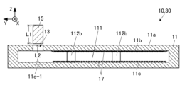
実施形態1の放熱基板10は、内部空間111を有する筐体11と、内部空間111を封止する封止体15とを備えている。筐体11は、内部空間111に通じる貫通孔13と、内天面11bと、内底面11cとを有してもよい。封止体15は貫通孔13を塞ぐことで内部空間111を封止してもよい。
The heat dissipation board 10 of the first embodiment includes a housing 11 having an internal space 111 and a sealing body 15 that seals the internal space 111. The housing 11 may have a through hole 13 communicating with the internal space 111, an inner top surface 11b, and an inner bottom surface 11c. The sealing body 15 may seal the internal space 111 by blocking the through hole 13 .
筐体11は、図1Cに示すように平板状(具体的には上下方向の寸法よりも水平方向の寸法が大きい平板状)であってもよい。貫通孔13は、筐体11の上面である第1面11aに開口し、第1面11aは平面状であってもよい。内部空間111は、水平方向に広がった空間(具体的には上下方向の寸法よりも水平方向の寸法が大きい空間)であってもよい。
The housing 11 may have a flat plate shape (specifically, a flat plate shape in which the horizontal dimension is larger than the vertical dimension), as shown in FIG. 1C. The through hole 13 opens on the first surface 11a, which is the upper surface of the housing 11, and the first surface 11a may be flat. The internal space 111 may be a space that extends horizontally (specifically, a space whose horizontal dimension is larger than its vertical dimension).
内部空間111には、内底面11cから内天面11bにかけて位置する1つ又は複数の支柱112bが位置してもよい。支柱112bは、内部空間111がつぶれたり膨らんだりしないように内部空間111の内側から筐体11を支持してもよい。
In the internal space 111, one or more columns 112b may be located from the inner bottom surface 11c to the inner top surface 11b. The support column 112b may support the housing 11 from inside the internal space 111 so that the internal space 111 does not collapse or expand.
筐体11及び封止体15は、金属であってもよい。当該金属の主成分は、銅、アルミ、チタン、ニッケル、ステンレス、あるいは、鉄系合金(例えばコバール(FeNiCo)等)であってもよい。主成分とは80質量%以上を占める成分を意味する。筐体11の金属と封止体15の金属とは主成分が同一であってもよい。さらに、筐体11の金属と封止体15の金属とは同一成分であってもよい。成分が同一とは、厳密に同一である場合のみでなく、誤差(誤差は公差の範囲内)を除いて同一である場合を含むものとする。
The housing 11 and the sealing body 15 may be made of metal. The main component of the metal may be copper, aluminum, titanium, nickel, stainless steel, or an iron-based alloy (for example, Kovar (FeNiCo), etc.). The main component means a component that accounts for 80% by mass or more. The metal of the housing 11 and the metal of the sealing body 15 may have the same main component. Furthermore, the metal of the housing 11 and the metal of the sealing body 15 may have the same composition. The term "components are the same" includes not only cases where the components are exactly the same, but also cases where the components are the same except for an error (the error is within the tolerance range).
上述した筐体11の材質は、少なくとも貫通孔13の内壁部12(図2を参照)の材質であり、筐体11の内壁部12を除いた部位は異なる材質であってもよい。内壁部12とは、筐体11において貫通孔13を囲いかつ貫通孔13に面した部位を意味し、貫通孔13から貫通孔13の直径の1/5~1/2の範囲内の厚みを有する部位を意味してもよい。
The material of the casing 11 described above is the material of at least the inner wall 12 of the through hole 13 (see FIG. 2), and the parts of the casing 11 other than the inner wall 12 may be made of a different material. The inner wall portion 12 refers to a portion of the housing 11 that surrounds the through hole 13 and faces the through hole 13, and has a thickness within the range of 1/5 to 1/2 of the diameter of the through hole 13. It may also mean a part that has.
放熱基板10は、空隙を有する空隙構造体17を備えていてもよい。空隙構造体17は、内部空間111内に位置してもよい。より具体的には、空隙構造体17は、内部空間111の内面(例えば内天面11b、内底面11c等)に接するように位置してもよく、あるいは、内面と一体化されてもよい。空隙構造体17は、液相流体を表面張力によって保持及び輸送可能なウイックとして作用する構成であってもよい。空隙構造体17は、繊維体、焼結体、多孔質体又は針状体の集合あるいは網状の構造であってもよい。あるいは、空隙構造体17は、複数の孔(具体的には細孔)を有するプレートを多層にした構造であってもよい。空隙構造体17は、金属又はセラミックスなどの材料から構成されてもよい。
The heat dissipation board 10 may include a void structure 17 having voids. The void structure 17 may be located within the interior space 111. More specifically, the void structure 17 may be located so as to be in contact with the inner surface (for example, the inner top surface 11b, the inner bottom surface 11c, etc.) of the internal space 111, or may be integrated with the inner surface. The void structure 17 may be configured to act as a wick that can retain and transport the liquid phase fluid by surface tension. The void structure 17 may be a fibrous body, a sintered body, a porous body, or an aggregate or network structure of needle-like bodies. Alternatively, the void structure 17 may have a multilayered structure of plates having a plurality of holes (specifically, pores). The void structure 17 may be made of a material such as metal or ceramics.
<ベイパーチャンバー>
本実施形態に係るベイパーチャンバー30は、放熱基板10と、内部空間111に位置する液相流体とを備え、内部空間111が減圧されていてもよい。液相流体には、水、アセトン、メタノール、アンモニアなどが適用されてもよい。当該構成により、放熱基板10のいずれかの箇所に熱が加えられた場合に、内部空間111の内部で液相流体の相転移(すなわち気化と凝縮)と液相流体及び液相流体が気化した気相流体が還流することで、上記の熱を速やかに拡散させることができる。放熱基板10に熱が加わった際には、液相流体が気化することで、内部空間111の内圧は筐体11の外よりも高くなってもよい。後述する実施形態2~8の放熱基板10A~10Gについても、上記と同様に構成することで本実施形態のベイパーチャンバーを構成できる。 <Vapor chamber>
The vapor chamber 30 according to the present embodiment includes a heat dissipation substrate 10 and a liquid phase fluid located in aninternal space 111, and the internal space 111 may be depressurized. Water, acetone, methanol, ammonia, etc. may be applied to the liquid phase fluid. With this configuration, when heat is applied to any part of the heat dissipation board 10, a phase transition (i.e., vaporization and condensation) of the liquid phase fluid occurs inside the internal space 111, and the liquid phase fluid and the liquid phase fluid are vaporized. By refluxing the gas phase fluid, the above heat can be rapidly diffused. When heat is applied to the heat dissipation board 10, the liquid phase fluid is vaporized, so that the internal pressure in the internal space 111 may become higher than that outside the housing 11. The vapor chamber of this embodiment can be constructed by configuring heat dissipation boards 10A to 10G of embodiments 2 to 8, which will be described later, in the same manner as described above.
本実施形態に係るベイパーチャンバー30は、放熱基板10と、内部空間111に位置する液相流体とを備え、内部空間111が減圧されていてもよい。液相流体には、水、アセトン、メタノール、アンモニアなどが適用されてもよい。当該構成により、放熱基板10のいずれかの箇所に熱が加えられた場合に、内部空間111の内部で液相流体の相転移(すなわち気化と凝縮)と液相流体及び液相流体が気化した気相流体が還流することで、上記の熱を速やかに拡散させることができる。放熱基板10に熱が加わった際には、液相流体が気化することで、内部空間111の内圧は筐体11の外よりも高くなってもよい。後述する実施形態2~8の放熱基板10A~10Gについても、上記と同様に構成することで本実施形態のベイパーチャンバーを構成できる。 <Vapor chamber>
The vapor chamber 30 according to the present embodiment includes a heat dissipation substrate 10 and a liquid phase fluid located in an
<封止部の詳細>
図2Aは、封止体の周辺を示す縦断面図である。図2Bは、図2AのB-B線における断面図である。 <Details of sealing part>
FIG. 2A is a vertical cross-sectional view showing the periphery of the sealed body. FIG. 2B is a cross-sectional view taken along line BB in FIG. 2A.
図2Aは、封止体の周辺を示す縦断面図である。図2Bは、図2AのB-B線における断面図である。 <Details of sealing part>
FIG. 2A is a vertical cross-sectional view showing the periphery of the sealed body. FIG. 2B is a cross-sectional view taken along line BB in FIG. 2A.
貫通孔13は、図2Bに示すように、横断面が円形状であってもよい。貫通孔13の形状に合わせて、封止体15は円柱状であってもよい。その他、貫通孔13は、横断面が、楕円状、長円状、多角形状、直線状の辺と曲がった辺とを有する形状など、様々な形状であってもよい。封止体15は、貫通孔13に対応した形状を有していてもよい。
The through hole 13 may have a circular cross section, as shown in FIG. 2B. The sealing body 15 may have a cylindrical shape in accordance with the shape of the through hole 13. In addition, the through-hole 13 may have various shapes in cross section, such as an elliptical shape, an elliptical shape, a polygonal shape, a shape having linear sides and curved sides. The sealing body 15 may have a shape corresponding to the through hole 13.
以下では、貫通孔13のうち、内部空間111との境に位置する開口を第1開口部13aと記し、外側の開口を第2開口部13bと記す(図2Aを参照)。また、筐体11における貫通孔13を囲う部位を内壁部12と記す。図2Aにおいて、第1開口部13aと第2開口部13bとを太一点鎖線で示す。また、図2A及び図2Bにおいて内壁部12を太点線により囲んで示す。
Hereinafter, of the through-hole 13, the opening located at the border with the internal space 111 will be referred to as a first opening 13a, and the outer opening will be referred to as a second opening 13b (see FIG. 2A). Further, a portion of the housing 11 that surrounds the through hole 13 is referred to as an inner wall portion 12. In FIG. 2A, the first opening 13a and the second opening 13b are indicated by thick dashed lines. Further, in FIGS. 2A and 2B, the inner wall portion 12 is shown surrounded by a thick dotted line.
貫通孔13は、第1開口部13aから第2開口部13bにかけて直線状に延びる構成であってもよい。
The through hole 13 may be configured to extend linearly from the first opening 13a to the second opening 13b.
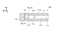
図2Aに示すように、封止体15は、内部空間111内に位置する第1部位15aと、貫通孔13に位置する第2部位15bとを有してもよい。第1部位15aは、内部空間111の第1内底面11c-1に接触していてもよい。第1内底面11c-1とは、内部空間111の内底面11cの一部であり、貫通孔13に沿って透視したときに、貫通孔13と重なる部位に相当する。
As shown in FIG. 2A, the sealing body 15 may have a first portion 15a located within the internal space 111 and a second portion 15b located in the through hole 13. The first portion 15a may be in contact with the first inner bottom surface 11c-1 of the internal space 111. The first inner bottom surface 11c-1 is a part of the inner bottom surface 11c of the internal space 111, and corresponds to a portion that overlaps with the through hole 13 when seen along the through hole 13.
封止体15の第2部位15bは、貫通孔13の内壁部12に圧力を加えた状態で密着していてもよいし、第2部位15bと内壁部12との間にろう材等の接合材が充填されていてもよい。
The second portion 15b of the sealing body 15 may be in close contact with the inner wall portion 12 of the through hole 13 under pressure, or may be bonded with a brazing material or the like between the second portion 15b and the inner wall portion 12. It may be filled with material.
縦断面において、第1部位15aの最大幅W15maxは、貫通孔13の最小幅W13minよりも大きくてもよい(すなわちW15max>W13min)。さらに、第1部位15aの最大幅W15maxは、第1開口部13aの幅W13aよりも大きくてもよい(すなわちW15max>W13a)。第1開口部13aとは、前述したように貫通孔13のうち内部空間111との境に位置する開口を意味する。第1開口部13aの幅W13aは、上記縦断面において第1開口部13aの一端から他端までを結んだ線分の長さを意味してもよい。当該縦断面は、第1開口部13aの重心と第2開口部13bの重心とを通る平断面を意味してもよい。上記の最大幅W15maxと最小幅W13minとの関係は、いずれの向きの縦断面においても成り立つ関係であってもよいし、幾つかの向きの縦断面を除いて成り立つ関係であってもよい。
In the longitudinal section, the maximum width W15max of the first portion 15a may be larger than the minimum width W13min of the through hole 13 (ie, W15max>W13min). Furthermore, the maximum width W15max of the first portion 15a may be larger than the width W13a of the first opening 13a (ie, W15max>W13a). The first opening 13a means the opening located in the through hole 13 at the border with the internal space 111, as described above. The width W13a of the first opening 13a may mean the length of a line segment connecting from one end of the first opening 13a to the other end in the longitudinal section. The longitudinal section may mean a plane section passing through the center of gravity of the first opening 13a and the center of gravity of the second opening 13b. The above relationship between the maximum width W15max and the minimum width W13min may be a relationship that holds true in any vertical cross section, or may hold true except for vertical cross sections in some directions.
上記の最小幅W13minと最大幅W15maxとの関係によれば、内部空間111の内圧が上昇した場合でも、封止体15が貫通孔13から抜けてしまう恐れが低減し、封止状態の保持が容易になる。上記の幅W13aと最大幅W15maxとの関係によっても、内部空間111の内圧が上昇した場合でも、封止体15が貫通孔13から抜けてしまう恐れがより低減し、封止状態の保持がより容易になる。
According to the above relationship between the minimum width W13min and the maximum width W15max, even if the internal pressure of the internal space 111 increases, the possibility that the sealing body 15 will come off from the through hole 13 is reduced, and the sealing state can be maintained. becomes easier. Due to the relationship between the width W13a and the maximum width W15max, even if the internal pressure of the internal space 111 increases, the risk of the sealing body 15 coming off from the through hole 13 is further reduced, and the sealing state is more easily maintained. becomes easier.
先にも説明したが、第1部位15aは第1内底面11c-1に接触していてもよい。当該構成によれば、内部空間111の内圧が上昇した際でも、第1部位15aの先端面が内部空間111の内圧に晒されにくい。よって、上昇した内圧によって封止体15に外に押し出す方向の力が作用することを低減できる。よって、封止体15が貫通孔13から抜ける方向に変位する恐れが低減され、内部空間111の封止状態の保持が容易になる。
As described above, the first portion 15a may be in contact with the first inner bottom surface 11c-1. According to this configuration, even when the internal pressure of the internal space 111 increases, the distal end surface of the first portion 15a is unlikely to be exposed to the internal pressure of the internal space 111. Therefore, it is possible to reduce the force acting on the sealing body 15 in the direction of pushing it outward due to the increased internal pressure. Therefore, the possibility that the sealing body 15 is displaced in the direction of coming out of the through hole 13 is reduced, and it becomes easier to maintain the sealed state of the internal space 111.
さらに、第1部位15aが第1内底面11c-1に接触していることにより、筐体11の封止体15の近傍部位の剛性が高まる。したがって、第1面11aに素子の端子又は導線を超音波ボンディングする場合に、ボンディングが容易になる。
Furthermore, since the first portion 15a is in contact with the first inner bottom surface 11c-1, the rigidity of the portion of the housing 11 near the sealing body 15 is increased. Therefore, when performing ultrasonic bonding of the terminals or conductive wires of the element to the first surface 11a, the bonding becomes easy.
<封止工程>
図1Bに示すように、封止前の封止体15の長さL1は、貫通孔13の外側の開口部(具体的には第2開口部13b、図2Aを参照)から第1内底面11c-1までの長さL2よりも長くてもよい。封止前の封止体15は、貫通孔13に通る太さを有していてもよい。 <Sealing process>
As shown in FIG. 1B, the length L1 of the sealedbody 15 before sealing is from the outer opening of the through hole 13 (specifically, the second opening 13b, see FIG. 2A) to the first inner bottom surface. It may be longer than the length L2 up to 11c-1. The sealed body 15 before sealing may have a thickness that allows it to pass through the through hole 13.
図1Bに示すように、封止前の封止体15の長さL1は、貫通孔13の外側の開口部(具体的には第2開口部13b、図2Aを参照)から第1内底面11c-1までの長さL2よりも長くてもよい。封止前の封止体15は、貫通孔13に通る太さを有していてもよい。 <Sealing process>
As shown in FIG. 1B, the length L1 of the sealed
封止工程は、封止体15の一端が第1内底面11c-1に接触するまで封止体15を貫通孔13に通す工程と、封止体15を更に押し込む工程とが含まれてもよい。更に押し込む工程により、図2Aに示すように、封止体15の第1部位15aが拡径するように変形し、第1部位15aの最大幅W15maxが貫通孔13の最小幅W13minよりも大きくなる。さらに、上記の変形の際、封止体15の第2部位15bが拡径することで、あるいは、第2部位15bの周囲がろう材などの接合材で充填されることで、貫通孔13が塞がれ、内部空間111が封止される。封止体15は、貫通孔13に通される前、あるいは、通された後に、第1面11aと封止体15の端面とが面一になるようにカット或いは研磨されてもよい。
The sealing process may include a step of passing the sealing body 15 through the through hole 13 until one end of the sealing body 15 contacts the first inner bottom surface 11c-1, and a step of further pushing the sealing body 15. good. Through the further pushing process, as shown in FIG. 2A, the first portion 15a of the sealing body 15 is deformed to expand in diameter, and the maximum width W15max of the first portion 15a becomes larger than the minimum width W13min of the through hole 13. . Furthermore, during the above deformation, the second portion 15b of the sealing body 15 expands in diameter, or the periphery of the second portion 15b is filled with a bonding material such as a brazing material, so that the through hole 13 is expanded. The internal space 111 is sealed. The sealing body 15 may be cut or polished before or after passing through the through hole 13 so that the first surface 11a and the end surface of the sealing body 15 are flush with each other.
上記の封止工程の前には、貫通孔13を介して内部空間111に液相流体が注入されてもよい。さらに、上記の封止工程は、減圧された空間で行われてもよい。当該工程により、内部空間111が液相流体を含みかつ減圧された状態で内部空間111を封止することができる。
Before the above sealing step, a liquid phase fluid may be injected into the internal space 111 through the through hole 13. Furthermore, the above sealing step may be performed in a reduced pressure space. Through this process, the internal space 111 can be sealed in a state where the internal space 111 contains the liquid phase fluid and is under reduced pressure.
上記の封止工程により達成される放熱基板10の封止構造によれば、貫通孔13、特に貫通孔13の第1面11a側の周辺に変形が生じにくく、よって、封止部周辺においても第1面11aの平坦性を向上できる。
According to the sealing structure of the heat dissipating substrate 10 achieved by the above-described sealing process, deformation hardly occurs in the through-holes 13, especially around the first surface 11a side of the through-holes 13, and therefore, even around the sealing part. The flatness of the first surface 11a can be improved.
(実施形態2)
図3Aは、実施形態2の放熱基板を示す横断面図である。図3Bは、図3AのB-B線における断面図である。実施形態2の放熱基板10Aは、内部空間111における封止体15の近傍の構造が異なる他は、実施形態1と同様であってもよい。 (Embodiment 2)
FIG. 3A is a cross-sectional view showing the heat dissipation board ofEmbodiment 2. FIG. 3B is a cross-sectional view taken along line BB in FIG. 3A. The heat dissipation board 10A of the second embodiment may be the same as that of the first embodiment except that the structure near the sealing body 15 in the internal space 111 is different.
図3Aは、実施形態2の放熱基板を示す横断面図である。図3Bは、図3AのB-B線における断面図である。実施形態2の放熱基板10Aは、内部空間111における封止体15の近傍の構造が異なる他は、実施形態1と同様であってもよい。 (Embodiment 2)
FIG. 3A is a cross-sectional view showing the heat dissipation board of
実施形態2の放熱基板10Aは、封止体15の側方に内部空間111の支持体112が位置してもよい。支持体112は、内部空間111がつぶれたり膨らんだりしないように内部空間111の内側から筐体11を支持する構造体であり、内部空間111の側壁であってもよいし、内底面11cから内天面11bにかけて位置する支柱であってもよい。図3Aでは、他の部位より厚い側壁が支持体112として適用されている。
In the heat dissipation substrate 10A of the second embodiment, the support body 112 of the internal space 111 may be located on the side of the sealing body 15. The support body 112 is a structure that supports the casing 11 from inside the interior space 111 to prevent the interior space 111 from collapsing or expanding. It may also be a pillar located over the top surface 11b. In FIG. 3A, a side wall that is thicker than the other portions is applied as a support 112.
支持体112は、封止体15の第1部位15aに接するように位置してもよい。支持体112と封止体15とは、内底面11cから内天面11bにかけた全体が接してもよいし、一部のみが接してもよいし、全体にわずかに隙間が空いていてもよい。
The support body 112 may be located so as to be in contact with the first portion 15a of the sealing body 15. The support body 112 and the sealing body 15 may be in contact with each other entirely from the inner bottom surface 11c to the inner top surface 11b, or only a part thereof may be in contact with each other, or there may be a slight gap between them. .
支持体112は、図3Aに示すように、封止体15から見て水平方向の三方に位置してもよいし、水平方向の二方又は一方に位置してもよい。一方、二方、三方とは、水平方向において全周囲を四等分したうちの1つの方向~3つの方向をそれぞれ意味する。
As shown in FIG. 3A, the supports 112 may be located on three sides in the horizontal direction when viewed from the sealing body 15, or may be located on two or one side in the horizontal direction. On the other hand, "two directions" and "three directions" refer to one to three directions obtained by dividing the entire circumference into four equal parts in the horizontal direction.
封止体15の側方に位置する支持体112は、他の領域の側壁115よりも厚くてもよい。
The support body 112 located on the side of the sealing body 15 may be thicker than the side wall 115 in other areas.
支持体112があることで、封止体15で貫通孔13を塞ぐ際に、貫通孔13の周辺が変形してしまうことをより低減できる。さらに、支持体112を厚い構成とすることで、上記の変形をより低減することができる。また、支持体112を厚い構成とすることで、貫通孔13が第1面11aの端に寄りすぎないように配置でき、設計段階において貫通孔13の配置自由度を高めることができるという利点が生じる。
The presence of the support body 112 can further reduce deformation of the periphery of the through hole 13 when the through hole 13 is closed with the sealing body 15. Furthermore, by making the support body 112 thick, the above deformation can be further reduced. Further, by making the support body 112 thick, the through holes 13 can be arranged so as not to be too close to the end of the first surface 11a, and there is an advantage that the degree of freedom in the arrangement of the through holes 13 can be increased at the design stage. arise.
図3Aに示すように、封止体15の三方に支持体112が位置する構成では、残りの一方に内部空間111の広い部分と繋がる通路111aが位置することになる。通路111aの幅W111は、貫通孔13の径φ13よりも大きくてもよいし、同一であってもよいし、小さくてもよい。小さいほうが、封止部近傍の筐体11の変形を低減する作用がより得られる。貫通孔13が円柱状でない場合、径は最小幅と言い換えてもよい。通路111aには、液相流体の循環が生じにくいため、通路111aは放熱作用が低減してもよい部位(例えば平面視における第1面11aの外周近傍)に位置してもよい。
As shown in FIG. 3A, in a configuration in which the supports 112 are located on three sides of the sealing body 15, a passage 111a that connects to a wide portion of the internal space 111 is located on the remaining one. The width W111 of the passage 111a may be larger than, the same as, or smaller than the diameter φ13 of the through hole 13. The smaller the size, the more effective the effect of reducing deformation of the casing 11 near the sealing part can be obtained. When the through hole 13 is not cylindrical, the diameter may be referred to as the minimum width. Since circulation of the liquid phase fluid is difficult to occur in the passage 111a, the passage 111a may be located at a portion where the heat dissipation effect may be reduced (for example, near the outer periphery of the first surface 11a in plan view).
(実施形態3)
図4Aは、実施形態3の放熱基板の縦断面図である。図4Bは、図4Aの部分C1の拡大図である。実施形態3の放熱基板10Bは、貫通孔13の内壁部12の結晶粒径、並びに、封止体15の結晶粒径に関して異なる他は、実施形態1、2の構成要素と同様であってもよい。 (Embodiment 3)
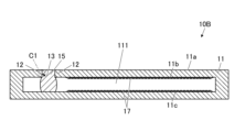
FIG. 4A is a longitudinal cross-sectional view of the heat dissipation board of Embodiment 3. FIG. 4B is an enlarged view of portion C1 in FIG. 4A. Theheat dissipation substrate 10B of the third embodiment is similar to the components of the first and second embodiments except for the crystal grain size of the inner wall portion 12 of the through hole 13 and the crystal grain size of the sealing body 15. good.
図4Aは、実施形態3の放熱基板の縦断面図である。図4Bは、図4Aの部分C1の拡大図である。実施形態3の放熱基板10Bは、貫通孔13の内壁部12の結晶粒径、並びに、封止体15の結晶粒径に関して異なる他は、実施形態1、2の構成要素と同様であってもよい。 (Embodiment 3)
FIG. 4A is a longitudinal cross-sectional view of the heat dissipation board of Embodiment 3. FIG. 4B is an enlarged view of portion C1 in FIG. 4A. The
封止体15の結晶粒径φ1と、内壁部12の結晶粒径φ2とは、下記(1)の条件を満たしてもよい。すなわち、封止体15の結晶粒径φ1は、内壁部12の結晶粒径φ2と同等以上であってもよい。
φ1 > 0.8×φ2 ・・・(1) The crystal grain size φ1 of the sealingbody 15 and the crystal grain size φ2 of the inner wall portion 12 may satisfy the following condition (1). That is, the crystal grain size φ1 of the sealing body 15 may be equal to or larger than the crystal grain size φ2 of the inner wall portion 12.
φ1 > 0.8×φ2 ... (1)
φ1 > 0.8×φ2 ・・・(1) The crystal grain size φ1 of the sealing
φ1 > 0.8×φ2 ... (1)
さらに、封止体15と内壁部12とは、主成分が同一の金属であってもよいし、同一成分の金属(例えば銅)であってもよい。
Further, the sealing body 15 and the inner wall portion 12 may have the same metal as the main component, or may have the same metal (for example, copper).
結晶粒径φ1、φ2は、下記(2)の条件を満たしてもよいし、さらに、下記(3)の条件を満たしてもよい。
φ1 ≧ φ2 ・・・(2)
φ1 > φ2 ・・・(3) The crystal grain sizes φ1 and φ2 may satisfy the condition (2) below, or may further satisfy the condition (3) below.
φ1 ≧ φ2 ...(2)
φ1 > φ2 ... (3)
φ1 ≧ φ2 ・・・(2)
φ1 > φ2 ・・・(3) The crystal grain sizes φ1 and φ2 may satisfy the condition (2) below, or may further satisfy the condition (3) below.
φ1 ≧ φ2 ...(2)
φ1 > φ2 ... (3)
一般に主成分の金属、あるいは、同一成分の金属においては、結晶粒径が大きい方が、応力が加わったときに変形しやすい。したがって、上記(1)の条件を満たことで、封止体15で貫通孔13を塞ぐ際に、筐体11の貫通孔13の周辺の変形をより低減しつつ、封止体15を変形させる作用が得られ、筐体11の外面側における封止部周辺の平坦性をより向上できる。さらに、上記(2)、(3)の条件を満たすことで、上記の作用がより得られ、封止部周辺の平坦性を更に向上することができる。
In general, in main component metals or metals with the same component, the larger the crystal grain size, the easier it is to deform when stress is applied. Therefore, by satisfying the condition (1) above, when closing the through hole 13 with the sealing body 15, the sealing body 15 can be deformed while further reducing deformation around the through hole 13 of the housing 11. Therefore, the flatness around the sealing portion on the outer surface side of the housing 11 can be further improved. Furthermore, by satisfying the conditions (2) and (3) above, the above effects can be better obtained, and the flatness around the sealing portion can be further improved.
上記の結晶粒径は、結晶粒径の平均値を意味し、次のように測定することができる。すなわち、該当部分の断面写真を用意し、断面写真上に所定長の線分を描き、当該線分と重なる結晶粒を数える。線分の端に重なる結晶粒は1/2個とする。そして、上記線分の長さ(具体的には断面写真の倍率を除算した長さ)を計数された結晶粒の個数で除算することで、一組のサンプルの結晶粒径を得る。さらに、線分の向きや位置を変えて複数組のサンプルの結晶粒径を計算し、当該計算された値の平均値を、計測対象の結晶粒径とする。
The above crystal grain size means the average value of crystal grain sizes, and can be measured as follows. That is, a cross-sectional photograph of the relevant portion is prepared, a line segment of a predetermined length is drawn on the cross-sectional photograph, and the crystal grains that overlap with the line segment are counted. The number of crystal grains that overlap the ends of the line segment is 1/2. Then, by dividing the length of the line segment (specifically, the length obtained by dividing the magnification of the cross-sectional photograph) by the number of counted crystal grains, the crystal grain size of a set of samples is obtained. Furthermore, the crystal grain sizes of a plurality of sets of samples are calculated by changing the direction and position of the line segment, and the average value of the calculated values is taken as the crystal grain size of the measurement target.
内壁部12の結晶粒径、並びに、封止体15の結晶粒径は、熱処理を加えることで大小に調整することができる。よって、封止前の筐体11の製造工程で加えられる熱処理と同等、あるいは、当該熱処理に所定の差異を加えた熱処理を封止体15に施すことで、上記(1)~(3)の条件を満たした結晶粒径を有する封止体15を製造することができる。
The crystal grain size of the inner wall portion 12 and the crystal grain size of the sealing body 15 can be adjusted to be large or small by applying heat treatment. Therefore, the above (1) to (3) can be achieved by subjecting the sealed body 15 to heat treatment that is equivalent to the heat treatment applied in the manufacturing process of the casing 11 before sealing, or with a predetermined difference added to the heat treatment. A sealed body 15 having a crystal grain size that satisfies the conditions can be manufactured.
なお、筐体11は、内壁部12と、その他の任意な箇所とで、略同一の結晶粒径を有していてもよい。
Note that the casing 11 may have substantially the same crystal grain size in the inner wall portion 12 and other arbitrary locations.
(実施形態4)
図5A~図5Cは、実施形態4、実施形態5及び実施形態6の放熱基板をそれぞれ示す縦断面図である。実施形態4~6の放熱基板10C~10Eは、封止体15の第1部位15aが接触する内部空間111の第1内底面11c-1の特性が異なる他は、実施形態1~3と同様であってもよい。 (Embodiment 4)
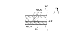
5A to 5C are vertical cross-sectional views showing the heat dissipation substrates of Embodiment 4, Embodiment 5, and Embodiment 6, respectively. Theheat dissipation substrates 10C to 10E of the fourth to sixth embodiments are the same as those of the first to third embodiments except that the characteristics of the first inner bottom surface 11c-1 of the internal space 111 with which the first portion 15a of the sealing body 15 contacts are different. It may be.
図5A~図5Cは、実施形態4、実施形態5及び実施形態6の放熱基板をそれぞれ示す縦断面図である。実施形態4~6の放熱基板10C~10Eは、封止体15の第1部位15aが接触する内部空間111の第1内底面11c-1の特性が異なる他は、実施形態1~3と同様であってもよい。 (Embodiment 4)
5A to 5C are vertical cross-sectional views showing the heat dissipation substrates of Embodiment 4, Embodiment 5, and Embodiment 6, respectively. The
実施形態4~6において、第1内底面11c-1のヤング率は、封止体15のヤング率よりも大きくてもよい。さらに、第1内底面11c-1のヤング率は、貫通孔13の内壁部12のヤング率よりも大きくてもよい。第1内底面11c-1とは、内部空間111の内底面11cのうち、封止体15の第1部位15aが接触する部位を意味する。ヤング率は、国際規格ISO14577に規定されたナノインデンテーション法により測定された値を意味してもよい。
In the fourth to sixth embodiments, the Young's modulus of the first inner bottom surface 11c-1 may be larger than the Young's modulus of the sealing body 15. Further, the Young's modulus of the first inner bottom surface 11c-1 may be larger than the Young's modulus of the inner wall portion 12 of the through hole 13. The first inner bottom surface 11c-1 refers to a portion of the inner bottom surface 11c of the internal space 111 that is in contact with the first portion 15a of the sealing body 15. Young's modulus may mean a value measured by the nanoindentation method specified in the international standard ISO14577.
当該構成によれば、封止体15で貫通孔13を塞ぐ際に、封止体15の第1部位15aが水平方向に膨らむ変形を効率的に発生させることができる。よって、第1内底面11c-1のヤング率が大きくない場合と比較して、少ないエネルギーで封止体15の第1部位15aを押し膨らませるこができる。したがって、封止体15から貫通孔13に加わるエネルギーも小さくすることができ、貫通孔13の周囲の変形を低減できる。よって、筐体11の外面側における封止部周辺の平坦性をより向上できる。
According to this configuration, when closing the through hole 13 with the sealing body 15, the first portion 15a of the sealing body 15 can be efficiently deformed to swell in the horizontal direction. Therefore, the first portion 15a of the sealing body 15 can be pushed and expanded with less energy than when the Young's modulus of the first inner bottom surface 11c-1 is not large. Therefore, the energy applied from the sealing body 15 to the through hole 13 can also be reduced, and deformation around the through hole 13 can be reduced. Therefore, the flatness around the sealing portion on the outer surface side of the housing 11 can be further improved.
上記のヤング率の関係を実現するために、実施形態4~6の放熱基板10C~10Eは次のように構成されてもよい。すなわち、図5Aの実施形態4の放熱基板10Cは、筐体11が、基部11Aと、基部11Aに接合された上部構造体11Bとを含んでもよい。そして、基部11Aが封止体15と異なる材料から構成されてもよい。
In order to realize the above Young's modulus relationship, the heat dissipating substrates 10C to 10E of embodiments 4 to 6 may be configured as follows. That is, in the heat dissipation board 10C of the fourth embodiment in FIG. 5A, the housing 11 may include a base 11A and an upper structure 11B joined to the base 11A. The base portion 11A may be made of a material different from that of the sealing body 15.
具体的には、上部構造体11B及び封止体15が銅などの金属から構成され、基部11Aがセラミックから構成されてもよい。当該セラミックには、主成分として窒化珪素(Si3N4)、炭化ケイ素(SiC)、ムライト又は窒化アルミニウム(AlN)、酸化アルミニウム(Al2O3)等を含んだ材料が適用されてもよい。
Specifically, the upper structure 11B and the sealing body 15 may be made of metal such as copper, and the base 11A may be made of ceramic. A material containing silicon nitride (Si 3 N 4 ), silicon carbide (SiC), mullite, aluminum nitride (AlN), aluminum oxide (Al 2 O 3 ), etc. as a main component may be applied to the ceramic. .
基部11Aと上部構造体11Bとはろう材等の接合材を介して接合されてもよい。そして、基部11Aと上部構造体11Bとの間に内部空間111が位置し、貫通孔13が上部構造体11Bに位置してもよい。そして、基部11Aの上面に第1内底面11c-1が含まれてもよい。
The base 11A and the upper structure 11B may be joined via a joining material such as a brazing material. The internal space 111 may be located between the base 11A and the upper structure 11B, and the through hole 13 may be located in the upper structure 11B. The upper surface of the base portion 11A may include a first inner bottom surface 11c-1.
図5Bの実施形態5の放熱基板10Dは、第1内底面11c-1と重なる部位に、筐体11の他の部位と異なる材質の板状又は膜状の部材11Dを有してもよい。部材11Dは、セラミックから構成され、ろう材等の接合材を介して筐体11の内底面11cに接合されていてもよい。当該セラミックは、主成分として窒化珪素(Si3N4)、炭化ケイ素(SiC)、ムライト又は窒化アルミニウム(AlN)、酸化アルミニウム(Al2O3)等を含んだ構成であってもよい。
The heat dissipation board 10D of the fifth embodiment in FIG. 5B may have a plate-like or film-like member 11D made of a different material from other parts of the casing 11 at a portion overlapping with the first inner bottom surface 11c-1. The member 11D may be made of ceramic and bonded to the inner bottom surface 11c of the housing 11 via a bonding material such as a brazing material. The ceramic may include silicon nitride (Si 3 N 4 ), silicon carbide (SiC), mullite, aluminum nitride (AlN), aluminum oxide (Al 2 O 3 ), or the like as a main component.
図5Cの実施形態6の放熱基板10Eは、筐体11の底部が多層構造を有し、底部の最上層(すなわち内底面11cとして露出する層)11Eが、筐体11のその他の部位と異なる材質から構成されてもよい。最上層11Eは、セラミックから構成されてもよい。当該セラミックは、主成分として窒化珪素(Si3N4)、炭化ケイ素(SiC)、ムライト又は窒化アルミニウム(AlN)、酸化アルミニウム(Al2O3)等を含んだ構成であってもよい。
In the heat dissipation board 10E of the sixth embodiment in FIG. 5C, the bottom of the casing 11 has a multilayer structure, and the top layer 11E of the bottom (that is, the layer exposed as the inner bottom surface 11c) is different from other parts of the casing 11. It may be made of any material. The top layer 11E may be made of ceramic. The ceramic may include silicon nitride (Si 3 N 4 ), silicon carbide (SiC), mullite, aluminum nitride (AlN), aluminum oxide (Al 2 O 3 ), or the like as a main component.
上記の実施形態4~6の放熱基板10C~10Eの構成により、上記のヤング率の関係を実現することができる。
The configuration of the heat dissipation substrates 10C to 10E of the fourth to sixth embodiments described above makes it possible to realize the above Young's modulus relationship.
<ヤング率の関係と封止体の形状>
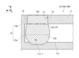
ここで、前述した実施形態1~6における封止体15の形状の詳細を説明する。図6Aは、実施形態1~3の封止体の形状を説明する図である。図6Bは、実施形態4~6の封止体の形状を説明する図である。実施形態1~3は、第1内底面11c-1のヤング率と、封止体15及び内壁部12のヤング率とが同等である。実施形態4~6は、第1内底面11c-1のヤング率の方が、封止体15及び内壁部12のヤング率よりも大きい。前述したように、貫通孔13のうち、内部空間111との境に位置する開口を第1開口部13aと呼び、外側の開口を第2開口部13bと呼ぶ。 <Relationship of Young's modulus and shape of sealed body>
Here, details of the shape of the sealingbody 15 in the first to sixth embodiments described above will be explained. FIG. 6A is a diagram illustrating the shape of the sealing body of Embodiments 1 to 3. FIG. 6B is a diagram illustrating the shape of the sealing body of Embodiments 4 to 6. In Embodiments 1 to 3, the Young's modulus of the first inner bottom surface 11c-1 and the Young's modulus of the sealing body 15 and the inner wall portion 12 are equivalent. In the fourth to sixth embodiments, the Young's modulus of the first inner bottom surface 11c-1 is larger than the Young's modulus of the sealing body 15 and the inner wall portion 12. As described above, in the through hole 13, the opening located at the border with the internal space 111 is called the first opening 13a, and the outer opening is called the second opening 13b.
ここで、前述した実施形態1~6における封止体15の形状の詳細を説明する。図6Aは、実施形態1~3の封止体の形状を説明する図である。図6Bは、実施形態4~6の封止体の形状を説明する図である。実施形態1~3は、第1内底面11c-1のヤング率と、封止体15及び内壁部12のヤング率とが同等である。実施形態4~6は、第1内底面11c-1のヤング率の方が、封止体15及び内壁部12のヤング率よりも大きい。前述したように、貫通孔13のうち、内部空間111との境に位置する開口を第1開口部13aと呼び、外側の開口を第2開口部13bと呼ぶ。 <Relationship of Young's modulus and shape of sealed body>
Here, details of the shape of the sealing
図6Aに示すように、実施形態1~3において、封止体15の第1部位15aは、貫通孔13の第1開口部13aに位置する上端部151と、第1内底面11c-1に接する下端部154と、上端部151と下端部154との間に位置する第1中間部152とを含む。そして、縦断面における第1部位15aの外形線は、上端部151から第1中間部152にかけて幅が漸次大きくなり、第1中間部152から下方にかけて幅が漸次小さくなるなだらかな曲線を有してもよい。封止体15が円柱状であれば上記の幅は径と言い換えてもよい。
As shown in FIG. 6A, in Embodiments 1 to 3, the first portion 15a of the sealing body 15 has an upper end portion 151 located at the first opening 13a of the through hole 13 and a first inner bottom surface 11c-1. It includes a lower end portion 154 that contacts, and a first intermediate portion 152 located between the upper end portion 151 and the lower end portion 154. The outline of the first portion 15a in the longitudinal section has a gentle curve in which the width gradually increases from the upper end portion 151 to the first intermediate portion 152, and the width gradually decreases from the first intermediate portion 152 downward. Good too. If the sealing body 15 has a cylindrical shape, the above width may be referred to as the diameter.
第1内底面11c-1は、凹んだ形状を有し、第1部位15aの先端が凹みに嵌っていてもよい。
The first inner bottom surface 11c-1 may have a concave shape, and the tip of the first portion 15a may fit into the concave.
第1部位15aの外形線に現れる膨らみ、並びに、第1内底面11c-1の凹みは、封止体15が貫通孔13を塞ぐ際に、封止体15が下方に押されることで形成された形状であってもよい。
The bulge appearing in the outline of the first portion 15a and the depression in the first inner bottom surface 11c-1 are formed by the sealing body 15 being pushed downward when the sealing body 15 closes the through hole 13. It may also have a different shape.
図6Bに示すように、実施形態4~6において、封止体15の第1部位15aは、実施形態1~3と同様に、上端部151、下端部154、第1中間部152を有してもよい。さらに、実施形態1~3と同様に、縦断面における第1部位15aの外形線は、上端部151から第1中間部152にかけて幅が漸次大きくなり、第1中間部から下方にかけて幅が漸次小さくなるなだらかな曲線を有してもよい。封止体15が円柱状であれば上記の幅は径と言い換えてもよい。
As shown in FIG. 6B, in Embodiments 4 to 6, the first portion 15a of the sealing body 15 has an upper end portion 151, a lower end portion 154, and a first intermediate portion 152, as in Embodiments 1 to 3. You can. Furthermore, similarly to Embodiments 1 to 3, the width of the outline of the first portion 15a in the longitudinal section gradually increases from the upper end portion 151 to the first intermediate portion 152, and the width gradually decreases from the first intermediate portion downward. It may have a gentle curve. If the sealing body 15 has a cylindrical shape, the above width may be referred to as the diameter.
加えて、実施形態4~6の第1部位15aは、第1中間部152と下端部154との間に第2中間部153を有し、縦断面における第1部位15aの外形線は、第2中間部153において幅が極小となる折れ曲がり153aを含んでもよい。幅が極小となる第2中間部153はくびれと呼んでもよい。
In addition, the first portion 15a of embodiments 4 to 6 has a second intermediate portion 153 between the first intermediate portion 152 and the lower end portion 154, and the outline of the first portion 15a in the longitudinal section is the same as the first portion 15a. The two intermediate portions 153 may include a bend 153a with a minimum width. The second intermediate portion 153 having the smallest width may be called a constriction.
実施形態4~6において、第1内底面11c-1は、平面状であり、封止体15の第1部位15aは、第2中間部153から下端部154へかけて幅が漸次大きくなっていてもよい。
In embodiments 4 to 6, the first inner bottom surface 11c-1 is planar, and the first portion 15a of the sealing body 15 has a width that gradually increases from the second intermediate portion 153 to the lower end portion 154. You can.
第1部位15aの外形線に現れる膨らみと第2中間部153の折れ曲がり(すなわちくびれの形状)は、封止体15が貫通孔13を塞ぐ際に、封止体15に圧力が加わることで形成される形状であってもよく、第1内底面11c-1のヤング率が大きいことで生じる。
The bulge that appears in the outline of the first portion 15a and the bend (that is, the shape of the constriction) of the second intermediate portion 153 are formed by pressure being applied to the sealing body 15 when the sealing body 15 closes the through hole 13. This is caused by the large Young's modulus of the first inner bottom surface 11c-1.
図6A及び図6Bに示した封止体15の形状により、貫通孔13の第2開口部13bの周辺が変形することを低減しつつ、貫通孔13を塞いで内部空間111を封止することができる。さらに、内部空間111の内圧が高低に変化した場合でも、内部空間111の封止を容易に維持することができる。
The shape of the sealing body 15 shown in FIGS. 6A and 6B allows the inner space 111 to be sealed by blocking the through hole 13 while reducing deformation of the periphery of the second opening 13b of the through hole 13. Can be done. Furthermore, even when the internal pressure of the internal space 111 changes in level, the sealing of the internal space 111 can be easily maintained.
(実施形態7)
図7は、実施形態7の放熱基板を示す縦断面図である。実施形態7の放熱基板10Fは、空隙構造体17に関する構成が異なる他は、実施形態1~6と同様であってもよい。図7では、筐体11の底部が他の部位と異なる材質である例を示しているが、筐体11の全体が同一の材質であってもよい。 (Embodiment 7)
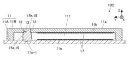
FIG. 7 is a longitudinal cross-sectional view showing a heat dissipation board of Embodiment 7. Theheat dissipation board 10F of the seventh embodiment may be the same as those of the first to sixth embodiments, except that the configuration regarding the gap structure 17 is different. Although FIG. 7 shows an example in which the bottom of the casing 11 is made of a different material from other parts, the entire casing 11 may be made of the same material.
図7は、実施形態7の放熱基板を示す縦断面図である。実施形態7の放熱基板10Fは、空隙構造体17に関する構成が異なる他は、実施形態1~6と同様であってもよい。図7では、筐体11の底部が他の部位と異なる材質である例を示しているが、筐体11の全体が同一の材質であってもよい。 (Embodiment 7)
FIG. 7 is a longitudinal cross-sectional view showing a heat dissipation board of Embodiment 7. The
空隙構造体17は、筐体11の内底面11cと一体化され、内底面11cの一部であってもよい。内底面11cは、封止体15の第1部位15aが接触する第1内底面11c-1と、第1内底面11c-1と隣り合う第2内底面11c-2とを含み、空隙構造体17は、第1内底面11c-1に位置する第1空隙構造体17-1と、第2内底面11c-2に位置する第2空隙構造体17-2とを含んでもよい。第2内底面11c-2とは、内底面11cのうち第1内底面11c-1の周辺の部位を意味してもよい。
The void structure 17 may be integrated with the inner bottom surface 11c of the housing 11, and may be a part of the inner bottom surface 11c. The inner bottom surface 11c includes a first inner bottom surface 11c-1 that is in contact with the first portion 15a of the sealing body 15, and a second inner bottom surface 11c-2 that is adjacent to the first inner bottom surface 11c-1. 17 may include a first void structure 17-1 located on the first inner bottom surface 11c-1 and a second void structure 17-2 located on the second inner bottom surface 11c-2. The second inner bottom surface 11c-2 may mean a portion of the inner bottom surface 11c around the first inner bottom surface 11c-1.
第1内底面11c-1に第1空隙構造体17-1が位置することで、封止工程において封止体15の先端が第1内底面11c-1に当たった後、さらに、封止体15を押し込む際に、封止体15の先端に摩擦力が作用する。したがって、封止体15の先端が第1内底面11c-1で滑って想定外の曲りが封止体15に生じてしまう恐れを低減できる。したがって、より安定的に封止工程を遂行でき、放熱基板10Fの歩留まりを向上できる。
By positioning the first cavity structure 17-1 on the first inner bottom surface 11c-1, after the tip of the sealing body 15 hits the first inner bottom surface 11c-1 in the sealing process, the sealing body When pushing in the sealing body 15, a frictional force acts on the tip of the sealing body 15. Therefore, it is possible to reduce the possibility that the tip of the sealing body 15 will slip on the first inner bottom surface 11c-1 and causing an unexpected bend in the sealing body 15. Therefore, the sealing process can be performed more stably, and the yield of the heat dissipation substrate 10F can be improved.
第1空隙構造体17-1の空隙率は、第2空隙構造体17-2の空隙率よりも小さくてもよい。空隙率とは、空隙構造体17の単位体積当たりの空隙が占める体積を意味する。当該空隙率の差異は、封止体15の先端と第1内底面11c-1との結合度が第1空隙構造体17-1により向上していることを意味する。したがって、上記構成により、第1空隙構造体17-1によるアンカー効果が得られ、封止体15が貫通孔13から抜ける方向に変位してしまうことをより低減できる。
The porosity of the first void structure 17-1 may be smaller than the porosity of the second void structure 17-2. The porosity refers to the volume occupied by voids per unit volume of the void structure 17. This difference in porosity means that the degree of bonding between the tip of the sealing body 15 and the first inner bottom surface 11c-1 is improved by the first void structure 17-1. Therefore, with the above configuration, the anchor effect by the first cavity structure 17-1 can be obtained, and the displacement of the sealing body 15 in the direction of coming out of the through hole 13 can be further reduced.
(実施形態8)
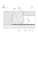
図8Aは、実施形態8の放熱基板を示す縦断面図である。図8Bは、図8Aの部分C2を示す拡大図である。実施形態8の放熱基板10Gは、貫通孔13を囲う内壁部12の一部が異なる他は、実施形態1~7と同様であってもよい。 (Embodiment 8)
FIG. 8A is a longitudinal cross-sectional view showing a heat dissipation board of Embodiment 8. FIG. 8B is an enlarged view showing portion C2 of FIG. 8A. Theheat dissipation board 10G of the eighth embodiment may be the same as those of the first to seventh embodiments, except that a portion of the inner wall portion 12 surrounding the through hole 13 is different.
図8Aは、実施形態8の放熱基板を示す縦断面図である。図8Bは、図8Aの部分C2を示す拡大図である。実施形態8の放熱基板10Gは、貫通孔13を囲う内壁部12の一部が異なる他は、実施形態1~7と同様であってもよい。 (Embodiment 8)
FIG. 8A is a longitudinal cross-sectional view showing a heat dissipation board of Embodiment 8. FIG. 8B is an enlarged view showing portion C2 of FIG. 8A. The
貫通孔13を囲う内壁部12は、内部空間111側に突出する突出部12aを含んでもよい。そして、突出部12aが封止体15に接触していてもよい。突出部12aは、貫通孔13と内部空間111との境(すなわち第1開口部13a)に位置し、突出部12aの先端は鋭角であってもよい。突出部12aの先端が鋭角とは、縦断面において突出部12aの先端の角部が鋭角であることを意味する。ここで、鋭角とは、微視的なレベルの丸みを無視したときの鋭角を意味する。すなわち、鋭角とは、図8Bに示すように、突出部12aの先端部を挟んで隣り合う第1辺12a-1の延長線と第2辺12a-2の延長線との成す角度θが鋭角であることを意味してもよい。
The inner wall portion 12 surrounding the through hole 13 may include a protrusion portion 12a that protrudes toward the internal space 111 side. The protruding portion 12a may be in contact with the sealing body 15. The protrusion 12a is located at the boundary between the through hole 13 and the internal space 111 (ie, the first opening 13a), and the tip of the protrusion 12a may have an acute angle. The term "the tip of the protrusion 12a has an acute angle" means that the corner of the tip of the protrusion 12a has an acute angle in a longitudinal section. Here, the acute angle means an acute angle when microscopic roundness is ignored. That is, as shown in FIG. 8B, an acute angle means that the angle θ formed by the extension line of the first side 12a-1 and the extension line of the second side 12a-2 that are adjacent to each other with the tip of the protrusion 12a sandwiched therebetween is an acute angle. It may also mean that
突出部12aは、例えば、次のように形成することができる。すなわち、筐体11に貫通孔13を形成する際に、内部空間111側の開口(すなわち第1開口部13a)にバリを残す。そして、当該バリの端が開口中央を向くように、上記バリを傾ける。当該状態で、封止体15を用いて封止工程を実行することで、突出部12aを形成できる。
For example, the protrusion 12a can be formed as follows. That is, when forming the through hole 13 in the housing 11, burrs are left in the opening on the internal space 111 side (ie, the first opening 13a). Then, the burr is tilted so that the end of the burr faces the center of the opening. In this state, by performing a sealing process using the sealant 15, the protrusion 12a can be formed.
突出部12aを有することで、内部空間111の内圧が上昇した場合でも、貫通孔13の第1開口部13aが広がりにくくなる。したがって、貫通孔13において封止体15が外方へ変位してしまう恐れをより低減でき、貫通孔13の内壁部12と封止体15との間の気密性をより向上できる。
By having the protrusion 12a, the first opening 13a of the through hole 13 becomes difficult to expand even when the internal pressure of the internal space 111 increases. Therefore, the possibility that the sealing body 15 is displaced outward in the through hole 13 can be further reduced, and the airtightness between the inner wall portion 12 of the through hole 13 and the sealing body 15 can be further improved.
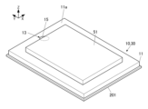
(素子の搭載例)
図9A及び図9Bは、実施形態の放熱基板に素子を搭載した例を示す縦断面図及び斜視図である。実施形態1の放熱基板10及びベイパーチャンバー30は、発熱する素子51が搭載されて、素子51の熱を放散させる。素子51は、パワー半導体など、大電流を流すパワー素子であってもよいし、その他の様々な素子であってもよい。素子51は、放熱基板10及びベイパーチャンバー30を介して、モジュール用基板201に搭載されてもよい。 (Example of mounting elements)
9A and 9B are a longitudinal cross-sectional view and a perspective view showing an example in which elements are mounted on a heat dissipation board according to an embodiment. The heat dissipation board 10 and the vapor chamber 30 of the first embodiment are mounted with theheat generating element 51 and dissipate the heat of the element 51. The element 51 may be a power element that allows a large current to flow, such as a power semiconductor, or may be various other elements. The element 51 may be mounted on the module substrate 201 via the heat dissipation substrate 10 and the vapor chamber 30.
図9A及び図9Bは、実施形態の放熱基板に素子を搭載した例を示す縦断面図及び斜視図である。実施形態1の放熱基板10及びベイパーチャンバー30は、発熱する素子51が搭載されて、素子51の熱を放散させる。素子51は、パワー半導体など、大電流を流すパワー素子であってもよいし、その他の様々な素子であってもよい。素子51は、放熱基板10及びベイパーチャンバー30を介して、モジュール用基板201に搭載されてもよい。 (Example of mounting elements)
9A and 9B are a longitudinal cross-sectional view and a perspective view showing an example in which elements are mounted on a heat dissipation board according to an embodiment. The heat dissipation board 10 and the vapor chamber 30 of the first embodiment are mounted with the
素子51は、図9A及び図9Bに示すように、第1面11aの貫通孔13及び封止体15が位置する領域に重なるように搭載されてもよいし、当該領域から外れて搭載されてもよい。あるいは、素子51の端子が、第1面11aの上記領域に接合されてもよい。端子は、導電性を有する接合材を介して接合されてもよいし、超音波ボンディング等により接合されてもよい。
As shown in FIGS. 9A and 9B, the element 51 may be mounted so as to overlap the area where the through hole 13 and the sealing body 15 of the first surface 11a are located, or may be mounted outside the area. Good too. Alternatively, the terminal of the element 51 may be joined to the above region of the first surface 11a. The terminals may be bonded via a conductive bonding material, or may be bonded by ultrasonic bonding or the like.
実施形態1の放熱基板10及びベイパーチャンバー30によれば、上述したように、筐体11の外面における封止部周辺の平坦性を向上できる。したがって、図9A及び図9Bのように、第1面11aに素子51を搭載する場合でも、封止部が素子51の搭載に障害になることを低減できる。
According to the heat dissipation substrate 10 and the vapor chamber 30 of the first embodiment, as described above, the flatness around the sealing portion on the outer surface of the housing 11 can be improved. Therefore, even when mounting the element 51 on the first surface 11a as shown in FIGS. 9A and 9B, it is possible to reduce the possibility that the sealing portion becomes an obstacle to mounting the element 51.
さらに、内部空間111に液相流体を注入しかつ内部空間111を減圧するための通路が、放熱基板10の側方に位置する別の構成と比較すれば、実施形態1の放熱基板10及びベイパーチャンバー30は、側方の平坦性を同様に高くすることができる。したがって、複数の放熱基板10及びベイパーチャンバー30を、1つのモジュール用基板201上に並べて搭載する場合に、隣り合う放熱基板10及びベイパーチャンバー30を近づけて搭載できるなど、放熱基板10及びベイパーチャンバー30の集約性を向上できる。さらに、放熱基板10及びベイパーチャンバー30の配置の自由度を向上できる。
Furthermore, compared to another configuration in which the passage for injecting the liquid phase fluid into the internal space 111 and depressurizing the internal space 111 is located on the side of the heat dissipating board 10, the heat dissipating board 10 and vapor of the first embodiment are The chamber 30 can have high lateral flatness as well. Therefore, when a plurality of heat dissipation boards 10 and vapor chambers 30 are mounted side by side on one module board 201, adjacent heat dissipation boards 10 and vapor chambers 30 can be mounted close together. can improve the aggregation of Furthermore, the degree of freedom in arranging the heat dissipation board 10 and the vapor chamber 30 can be improved.
図9A及び図9Bの放熱基板10は、実施形態2~8の放熱基板10A~10Gに代替されてもよく、当該代替された構成についても、上記と同様の作用を奏することができる。
The heat dissipation board 10 of FIGS. 9A and 9B may be replaced with the heat dissipation boards 10A to 10G of Embodiments 2 to 8, and the replaced configuration can also provide the same effect as described above.
以上、本開示の各実施形態について説明した。しかし、本開示の放熱基板及びベイパーチャンバーは、上記実施形態に限られるものでない。実施形態で示した細部は、発明の趣旨を逸脱しない範囲で適宜変更可能である。
Each embodiment of the present disclosure has been described above. However, the heat dissipation substrate and vapor chamber of the present disclosure are not limited to the above embodiments. Details shown in the embodiments can be changed as appropriate without departing from the spirit of the invention.
以下、本開示の一実施形態を示す。一実施形態において、
(1)放熱基板は、
内部空間を有する筐体と、
前記内部空間を封止する封止体と、
を備え、
前記筐体は、前記内部空間に繋がる貫通孔と、内底面と、を有し、
前記封止体は、前記内部空間に位置する第1部位と、前記貫通孔に位置する第2部位とを有し、
前記第1部位は、前記内底面に接触し、
縦断面において、前記第1部位の最大幅が、前記貫通孔の最小幅よりも大きい。 An embodiment of the present disclosure will be described below. In one embodiment,
(1) The heat dissipation board is
a casing having an internal space;
a sealing body that seals the internal space;
Equipped with
The casing has a through hole connected to the internal space and an inner bottom surface,
The sealing body has a first part located in the internal space and a second part located in the through hole,
the first portion contacts the inner bottom surface;
In the longitudinal section, the maximum width of the first portion is larger than the minimum width of the through hole.
(2)上記(1)の放熱基板は、
前記貫通孔は、前記内部空間との境に位置する第1開口部を含み、
縦断面において、前記第1部位の最大幅が、前記第1開口部の幅よりも大きい。 (2) The heat dissipation board of (1) above is
The through hole includes a first opening located at a border with the internal space,
In the longitudinal section, the maximum width of the first portion is larger than the width of the first opening.
(3)上記(1)又は(2)の放熱基板は、
前記筐体は平面状の第1面を有し、
前記貫通孔の一端が前記第1面に位置する。 (3) The heat dissipation board of (1) or (2) above is
The casing has a planar first surface,
One end of the through hole is located on the first surface.
前記筐体は平面状の第1面を有し、
前記貫通孔の一端が前記第1面に位置する。 (3) The heat dissipation board of (1) or (2) above is
The casing has a planar first surface,
One end of the through hole is located on the first surface.
(4)上記(1)から(3)のいずれか一項の放熱基板は、
前記筐体は、前記貫通孔を囲う内壁部を有し、
前記封止体の結晶粒径がφ1であり、
前記内壁部の結晶粒径がφ2であり、
φ1 > 0.8 × φ2
である。 (4) The heat dissipation board according to any one of (1) to (3) above,
The casing has an inner wall portion surrounding the through hole,
The crystal grain size of the sealed body is φ1,
The crystal grain size of the inner wall portion is φ2,
φ1 > 0.8 × φ2
It is.
(5)上記(4)の放熱基板は、
前記内壁部と前記封止体とは主成分が同一の金属である。 (5) The heat dissipation board of (4) above is
The inner wall portion and the sealing body are made of the same metal as a main component.
前記内壁部と前記封止体とは主成分が同一の金属である。 (5) The heat dissipation board of (4) above is
The inner wall portion and the sealing body are made of the same metal as a main component.
(6)上記(1)から(5)のいずれか一項の放熱基板は、
前記内底面は、前記封止体が接触する第1内底面を含み、
前記筐体は、前記貫通孔を囲う内壁部を有し、
前記第1内底面のヤング率が、前記封止体のヤング率よりも高く、
前記第1内底面のヤング率が、前記内壁部のヤング率よりも高い。 (6) The heat dissipation board according to any one of (1) to (5) above,
The inner bottom surface includes a first inner bottom surface with which the sealing body contacts,
The casing has an inner wall portion surrounding the through hole,
The Young's modulus of the first inner bottom surface is higher than the Young's modulus of the sealed body,
The Young's modulus of the first inner bottom surface is higher than the Young's modulus of the inner wall portion.
(7)上記(1)から(6)のいずれか一項の放熱基板は、
空隙を有する空隙構造体を更に備え、
前記空隙構造体は前記内底面に位置し、
前記内底面は、前記封止体が接触する第1内底面と、前記第1内底面に隣り合う第2内底面とを含み、
前記空隙構造体は、前記第1内底面に位置する第1空隙構造体と、前記第2内底面に位置する第2空隙構造体と、を含み、
前記第1空隙構造体の空隙率が、前記第2空隙構造体の空隙率よりも小さい。 (7) The heat dissipation board according to any one of (1) to (6) above,
further comprising a void structure having voids;
The void structure is located on the inner bottom surface,
The inner bottom surface includes a first inner bottom surface with which the sealing body contacts and a second inner bottom surface adjacent to the first inner bottom surface,
The void structure includes a first void structure located on the first inner bottom surface and a second void structure located on the second inner bottom surface,
The porosity of the first void structure is smaller than the porosity of the second void structure.
(8)上記(1)から(7)のいずれか一項の放熱基板は、
前記筐体は、前記貫通孔を囲う内壁部を有し、
前記内壁部は、前記内部空間側に位置する突出部を含み、
前記突出部が、前記封止体に接触している。 (8) The heat dissipation board according to any one of (1) to (7) above,
The casing has an inner wall portion surrounding the through hole,
The inner wall portion includes a protrusion located on the inner space side,
The protrusion is in contact with the sealing body.
(9)上記(1)から(8)のいずれか一項の放熱基板は、
前記貫通孔は、前記内部空間との境に位置する第1開口部を含み、
前記封止体の前記第1部位は、前記第1開口部に位置する上端部と、前記内底面に接する下端部と、前記上端部と前記下端部との間に位置する第1中間部とを有し、
縦断面における前記第1部位の外形線は、前記上端部から前記第1中間部にかけて前記第1部位の幅が漸次大きくなり、前記第1中間部から下方にかけて前記第1部位の幅が漸次小さくなる曲線を含む。 (9) The heat dissipation board according to any one of (1) to (8) above,
The through hole includes a first opening located at a border with the internal space,
The first portion of the sealing body includes an upper end portion located at the first opening, a lower end portion in contact with the inner bottom surface, and a first intermediate portion located between the upper end portion and the lower end portion. has
The outline of the first portion in a longitudinal section is such that the width of the first portion gradually increases from the upper end portion to the first intermediate portion, and the width of the first portion gradually decreases from the first intermediate portion downward. Contains a curve.
(10)上記(9)の放熱基板は、
前記封止体の前記第1部位は、前記第1中間部と前記下端部との間に第2中間部を有し、
縦断面における前記第1部位の外形線は、前記第2中間部において前記第1部位の幅が極小となる折れ曲がりを含む。 (10) The heat dissipation board of (9) above is
The first portion of the sealing body has a second intermediate portion between the first intermediate portion and the lower end portion,
The outline of the first portion in the longitudinal section includes a bend where the width of the first portion becomes minimum at the second intermediate portion.
一実施形態において、
(11)ベイパーチャンバーは、
(1)から(10)のいずれか一項の放熱基板と、
前記内部空間に位置する液相流体と、
を備える。 In one embodiment,
(11) The vapor chamber is
The heat dissipation board according to any one of (1) to (10),
a liquid phase fluid located in the internal space;
Equipped with.
(11)ベイパーチャンバーは、
(1)から(10)のいずれか一項の放熱基板と、
前記内部空間に位置する液相流体と、
を備える。 In one embodiment,
(11) The vapor chamber is
The heat dissipation board according to any one of (1) to (10),
a liquid phase fluid located in the internal space;
Equipped with.
本開示は、放熱基板及びベイパーチャンバーに利用できる。
The present disclosure can be used for heat dissipation substrates and vapor chambers.
10、10A~10G 放熱基板
11 筐体
11a 第1面
11A 基部
11B 上部構造体
11D 部材
11E 最上層
11c 内底面
11c-1 第1内底面
11c-2 第2内底面
12 内壁部
12a 突出部
13 貫通孔
13a 第1開口部
13b 第2開口部
15 封止体
15a 第1部位
15b 第2部位
17 空隙構造体
17-1 第1空隙構造体
17-2 第2空隙構造体
51 素子
111 内部空間
111a 通路
112 支持体
115 側壁
151 上端部
152 第1中間部
153 第2中間部
153a 折れ曲がり
154 下端部
201 モジュール用基板
W15max 最大幅
W13min 最小幅
W13a 幅 10, 10A to 10GHeat dissipation board 11 Housing 11a First surface 11A Base 11B Upper structure 11D Member 11E Top layer 11c Inner bottom surface 11c-1 First inner bottom surface 11c-2 Second inner bottom surface 12 Inner wall portion 12a Projection portion 13 Penetration Hole 13a First opening 13b Second opening 15 Sealing body 15a First part 15b Second part 17 Cavity structure 17-1 First cavity structure 17-2 Second cavity structure 51 Element 111 Internal space 111a Passage 112 Support body 115 Side wall 151 Upper end portion 152 First intermediate portion 153 Second intermediate portion 153a Bend 154 Lower end portion 201 Module substrate W15max Maximum width W13min Minimum width W13a Width
11 筐体
11a 第1面
11A 基部
11B 上部構造体
11D 部材
11E 最上層
11c 内底面
11c-1 第1内底面
11c-2 第2内底面
12 内壁部
12a 突出部
13 貫通孔
13a 第1開口部
13b 第2開口部
15 封止体
15a 第1部位
15b 第2部位
17 空隙構造体
17-1 第1空隙構造体
17-2 第2空隙構造体
51 素子
111 内部空間
111a 通路
112 支持体
115 側壁
151 上端部
152 第1中間部
153 第2中間部
153a 折れ曲がり
154 下端部
201 モジュール用基板
W15max 最大幅
W13min 最小幅
W13a 幅 10, 10A to 10G
Claims (11)
- 内部空間を有する筐体と、
前記内部空間を封止する封止体と、
を備え、
前記筐体は、前記内部空間に繋がる貫通孔と、内底面と、を有し、
前記封止体は、前記内部空間に位置する第1部位と、前記貫通孔に位置する第2部位とを有し、
前記第1部位は、前記内底面に接触し、
縦断面において、前記第1部位の最大幅が、前記貫通孔の最小幅よりも大きい、
放熱基板。 a casing having an internal space;
a sealing body that seals the internal space;
Equipped with
The casing has a through hole connected to the internal space and an inner bottom surface,
The sealing body has a first part located in the internal space and a second part located in the through hole,
the first portion contacts the inner bottom surface;
In a longitudinal section, the maximum width of the first portion is larger than the minimum width of the through hole;
heat dissipation board. - 前記貫通孔は、前記内部空間との境に位置する第1開口部を含み、
縦断面において、前記第1部位の最大幅が、前記第1開口部の幅よりも大きい、
請求項1記載の放熱基板。 The through hole includes a first opening located at a border with the internal space,
In a longitudinal section, the maximum width of the first portion is larger than the width of the first opening.
The heat dissipation board according to claim 1. - 前記筐体は平面状の第1面を有し、
前記貫通孔の一端が前記第1面に位置する、
請求項1記載の放熱基板。 The casing has a planar first surface,
one end of the through hole is located on the first surface;
The heat dissipation board according to claim 1. - 前記筐体は、前記貫通孔を囲う内壁部を有し、
前記封止体の結晶粒径がφ1であり、
前記内壁部の結晶粒径がφ2であり、
φ1 > 0.8 × φ2
である請求項1記載の放熱基板。 The casing has an inner wall portion surrounding the through hole,
The crystal grain size of the sealed body is φ1,
The crystal grain size of the inner wall portion is φ2,
φ1 > 0.8 × φ2
The heat dissipation board according to claim 1. - 前記内壁部と前記封止体とは主成分が同一の金属である、
請求項4記載の放熱基板。 The inner wall portion and the sealing body are made of the same metal as a main component,
The heat dissipation board according to claim 4. - 前記内底面は、前記封止体が接触する第1内底面を含み、
前記筐体は、前記貫通孔を囲う内壁部を有し、
前記第1内底面のヤング率が、前記封止体のヤング率よりも高く、
前記第1内底面のヤング率が、前記内壁部のヤング率よりも高い、
請求項1記載の放熱基板。 The inner bottom surface includes a first inner bottom surface with which the sealing body contacts,
The casing has an inner wall portion surrounding the through hole,
The Young's modulus of the first inner bottom surface is higher than the Young's modulus of the sealed body,
The Young's modulus of the first inner bottom surface is higher than the Young's modulus of the inner wall portion.
The heat dissipation board according to claim 1. - 空隙を有する空隙構造体を更に備え、
前記空隙構造体は前記内底面に位置し、
前記内底面は、前記封止体が接触する第1内底面と、前記第1内底面に隣り合う第2内底面とを含み、
前記空隙構造体は、前記第1内底面に位置する第1空隙構造体と、前記第2内底面に位置する第2空隙構造体と、を含み、
前記第1空隙構造体の空隙率が、前記第2空隙構造体の空隙率よりも小さい、
請求項1記載の放熱基板。 further comprising a void structure having voids;
The void structure is located on the inner bottom surface,
The inner bottom surface includes a first inner bottom surface with which the sealing body contacts and a second inner bottom surface adjacent to the first inner bottom surface,
The void structure includes a first void structure located on the first inner bottom surface and a second void structure located on the second inner bottom surface,
The porosity of the first void structure is smaller than the porosity of the second void structure.
The heat dissipation board according to claim 1. - 前記筐体は、前記貫通孔を囲う内壁部を有し、
前記内壁部は、前記内部空間側に位置する突出部を含み、
前記突出部が、前記封止体に接触している、
請求項1記載の放熱基板。 The casing has an inner wall portion surrounding the through hole,
The inner wall portion includes a protrusion located on the inner space side,
the protrusion is in contact with the sealing body;
The heat dissipation board according to claim 1. - 前記貫通孔は、前記内部空間との境に位置する第1開口部を含み、
前記封止体の前記第1部位は、前記第1開口部に位置する上端部と、前記内底面に接する下端部と、前記上端部と前記下端部との間に位置する第1中間部とを有し、
縦断面における前記第1部位の外形線は、前記上端部から前記第1中間部にかけて前記第1部位の幅が漸次大きくなり、前記第1中間部から下方にかけて前記第1部位の幅が漸次小さくなる曲線を含む、
請求項1記載の放熱基板。 The through hole includes a first opening located at a border with the internal space,
The first portion of the sealing body includes an upper end portion located at the first opening, a lower end portion in contact with the inner bottom surface, and a first intermediate portion located between the upper end portion and the lower end portion. has
The outline of the first portion in a longitudinal section is such that the width of the first portion gradually increases from the upper end portion to the first intermediate portion, and the width of the first portion gradually decreases from the first intermediate portion downward. including the curve
The heat dissipation board according to claim 1. - 前記封止体の前記第1部位は、前記第1中間部と前記下端部との間に第2中間部を有し、
縦断面における前記第1部位の外形線は、前記第2中間部において前記第1部位の幅が極小となる折れ曲がりを含む、
請求項9記載の放熱基板。 The first portion of the sealing body has a second intermediate portion between the first intermediate portion and the lower end portion,
The outline of the first portion in the longitudinal section includes a bend in which the width of the first portion becomes minimum at the second intermediate portion.
The heat dissipation board according to claim 9. - 請求項1記載の放熱基板と、
前記内部空間に位置する液相流体と、
を備えるベイパーチャンバー。 The heat dissipation board according to claim 1;
a liquid phase fluid located in the internal space;
Vapor chamber with.
Applications Claiming Priority (2)
| Application Number | Priority Date | Filing Date | Title |
|---|---|---|---|
| JP2022117281 | 2022-07-22 | ||
| JP2022-117281 | 2022-07-22 |
Publications (1)
| Publication Number | Publication Date |
|---|---|
| WO2024019108A1 true WO2024019108A1 (en) | 2024-01-25 |
Family
ID=89617877
Family Applications (1)
| Application Number | Title | Priority Date | Filing Date |
|---|---|---|---|
| PCT/JP2023/026555 WO2024019108A1 (en) | 2022-07-22 | 2023-07-20 | Heat-emitting substrate and vapor chamber |
Country Status (1)
| Country | Link |
|---|---|
| WO (1) | WO2024019108A1 (en) |
Citations (7)
| Publication number | Priority date | Publication date | Assignee | Title |
|---|---|---|---|---|
| JPS53106961A (en) * | 1977-02-28 | 1978-09-18 | Ngk Spark Plug Co Ltd | Ceramic heating pipes and manufacturing method |
| JPS5885555A (en) * | 1981-11-17 | 1983-05-21 | Ngk Spark Plug Co Ltd | Ceramic heat sink |
| JPH0321679U (en) * | 1989-06-29 | 1991-03-05 | ||
| JP2007315745A (en) * | 2005-09-01 | 2007-12-06 | Fuchigami Micro:Kk | Heat pipe and its manufacturing method |
| JP4035155B1 (en) * | 2006-07-28 | 2008-01-16 | 株式会社渕上ミクロ | Heat pipe and manufacturing method thereof |
| CN106225533A (en) * | 2016-07-29 | 2016-12-14 | 苏州聚力电机有限公司 | The mouth-sealing method of temperature-uniforming plate |
| WO2021182644A1 (en) * | 2020-03-13 | 2021-09-16 | 古河電気工業株式会社 | Vapor chamber and method for manufacturing vapor chamber |
-
2023
- 2023-07-20 WO PCT/JP2023/026555 patent/WO2024019108A1/en unknown
Patent Citations (7)
| Publication number | Priority date | Publication date | Assignee | Title |
|---|---|---|---|---|
| JPS53106961A (en) * | 1977-02-28 | 1978-09-18 | Ngk Spark Plug Co Ltd | Ceramic heating pipes and manufacturing method |
| JPS5885555A (en) * | 1981-11-17 | 1983-05-21 | Ngk Spark Plug Co Ltd | Ceramic heat sink |
| JPH0321679U (en) * | 1989-06-29 | 1991-03-05 | ||
| JP2007315745A (en) * | 2005-09-01 | 2007-12-06 | Fuchigami Micro:Kk | Heat pipe and its manufacturing method |
| JP4035155B1 (en) * | 2006-07-28 | 2008-01-16 | 株式会社渕上ミクロ | Heat pipe and manufacturing method thereof |
| CN106225533A (en) * | 2016-07-29 | 2016-12-14 | 苏州聚力电机有限公司 | The mouth-sealing method of temperature-uniforming plate |
| WO2021182644A1 (en) * | 2020-03-13 | 2021-09-16 | 古河電気工業株式会社 | Vapor chamber and method for manufacturing vapor chamber |
Similar Documents
| Publication | Publication Date | Title |
|---|---|---|
| CN107532860B (en) | High performance two-phase cooling apparatus | |
| CN108700282B (en) | High performance two-phase cooling device for portable applications | |
| JP2018503058A5 (en) | ||
| CN102811030B (en) | Vibration element and manufacture method, oscillator, electronic installation and electronics | |
| WO2018198354A1 (en) | Vapor chamber | |
| WO2016189952A1 (en) | Electronic component | |
| WO2018199215A1 (en) | Vapor chamber | |
| JP2012169678A (en) | Circuit board, semiconductor module using the same, and circuit board manufacturing method | |
| JP2006345518A (en) | Piezoelectric resonator and assembly comprising the piezoelectric resonator enclosed in case | |
| US20150076685A1 (en) | Flow path member, and heat exchanger and semiconductor device using the same | |
| CN110869689A (en) | Liquid absorption core structure and heat pipe containing liquid absorption core structure | |
| WO2024019108A1 (en) | Heat-emitting substrate and vapor chamber | |
| JP5278044B2 (en) | Package member, method for manufacturing the package member, and piezoelectric vibration device using the package member | |
| US8414704B2 (en) | Bonding structure and semiconductor device manufacturing apparatus | |
| WO2018198350A1 (en) | Vapor chamber | |
| JP5004837B2 (en) | Structure and electronic device | |
| WO2023190524A1 (en) | Heat dissipation plate and vapor chamber | |
| CN114061345A (en) | Heat conduction member and method for manufacturing heat conduction member | |
| JP2006313790A (en) | Through-hole structure of substrate | |
| JP7244712B2 (en) | package | |
| KR20190116092A (en) | Ceramic structure | |
| CN112005366A (en) | Heat dissipation substrate and electronic device | |
| US11387805B2 (en) | Electronic component | |
| JP6769830B2 (en) | Semiconductor packages and semiconductor devices | |
| WO2024041095A1 (en) | Package substrate having micro-structured chamber and manufacturing method therefor |
Legal Events
| Date | Code | Title | Description |
|---|---|---|---|
| 121 | Ep: the epo has been informed by wipo that ep was designated in this application |
Ref document number: 23843031 Country of ref document: EP Kind code of ref document: A1 |