WO2024018939A1 - 車輌用灯具 - Google Patents
車輌用灯具 Download PDFInfo
- Publication number
- WO2024018939A1 WO2024018939A1 PCT/JP2023/025407 JP2023025407W WO2024018939A1 WO 2024018939 A1 WO2024018939 A1 WO 2024018939A1 JP 2023025407 W JP2023025407 W JP 2023025407W WO 2024018939 A1 WO2024018939 A1 WO 2024018939A1
- Authority
- WO
- WIPO (PCT)
- Prior art keywords
- light
- light guide
- control
- section
- incident
- Prior art date
- Legal status (The legal status is an assumption and is not a legal conclusion. Google has not performed a legal analysis and makes no representation as to the accuracy of the status listed.)
- Ceased
Links
Images




Classifications
-
- F—MECHANICAL ENGINEERING; LIGHTING; HEATING; WEAPONS; BLASTING
- F21—LIGHTING
- F21S—NON-PORTABLE LIGHTING DEVICES; SYSTEMS THEREOF; VEHICLE LIGHTING DEVICES SPECIALLY ADAPTED FOR VEHICLE EXTERIORS
- F21S43/00—Signalling devices specially adapted for vehicle exteriors, e.g. brake lamps, direction indicator lights or reversing lights
- F21S43/10—Signalling devices specially adapted for vehicle exteriors, e.g. brake lamps, direction indicator lights or reversing lights characterised by the light source
- F21S43/13—Signalling devices specially adapted for vehicle exteriors, e.g. brake lamps, direction indicator lights or reversing lights characterised by the light source characterised by the type of light source
- F21S43/14—Light emitting diodes [LED]
-
- F—MECHANICAL ENGINEERING; LIGHTING; HEATING; WEAPONS; BLASTING
- F21—LIGHTING
- F21S—NON-PORTABLE LIGHTING DEVICES; SYSTEMS THEREOF; VEHICLE LIGHTING DEVICES SPECIALLY ADAPTED FOR VEHICLE EXTERIORS
- F21S43/00—Signalling devices specially adapted for vehicle exteriors, e.g. brake lamps, direction indicator lights or reversing lights
- F21S43/20—Signalling devices specially adapted for vehicle exteriors, e.g. brake lamps, direction indicator lights or reversing lights characterised by refractors, transparent cover plates, light guides or filters
- F21S43/235—Light guides
- F21S43/236—Light guides characterised by the shape of the light guide
- F21S43/239—Light guides characterised by the shape of the light guide plate-shaped
-
- F—MECHANICAL ENGINEERING; LIGHTING; HEATING; WEAPONS; BLASTING
- F21—LIGHTING
- F21S—NON-PORTABLE LIGHTING DEVICES; SYSTEMS THEREOF; VEHICLE LIGHTING DEVICES SPECIALLY ADAPTED FOR VEHICLE EXTERIORS
- F21S43/00—Signalling devices specially adapted for vehicle exteriors, e.g. brake lamps, direction indicator lights or reversing lights
- F21S43/20—Signalling devices specially adapted for vehicle exteriors, e.g. brake lamps, direction indicator lights or reversing lights characterised by refractors, transparent cover plates, light guides or filters
- F21S43/235—Light guides
- F21S43/236—Light guides characterised by the shape of the light guide
- F21S43/241—Light guides characterised by the shape of the light guide of complex shape
-
- F—MECHANICAL ENGINEERING; LIGHTING; HEATING; WEAPONS; BLASTING
- F21—LIGHTING
- F21S—NON-PORTABLE LIGHTING DEVICES; SYSTEMS THEREOF; VEHICLE LIGHTING DEVICES SPECIALLY ADAPTED FOR VEHICLE EXTERIORS
- F21S43/00—Signalling devices specially adapted for vehicle exteriors, e.g. brake lamps, direction indicator lights or reversing lights
- F21S43/20—Signalling devices specially adapted for vehicle exteriors, e.g. brake lamps, direction indicator lights or reversing lights characterised by refractors, transparent cover plates, light guides or filters
- F21S43/235—Light guides
- F21S43/242—Light guides characterised by the emission area
- F21S43/243—Light guides characterised by the emission area emitting light from one or more of its extremities
-
- G—PHYSICS
- G02—OPTICS
- G02B—OPTICAL ELEMENTS, SYSTEMS OR APPARATUS
- G02B6/00—Light guides; Structural details of arrangements comprising light guides and other optical elements, e.g. couplings
-
- F—MECHANICAL ENGINEERING; LIGHTING; HEATING; WEAPONS; BLASTING
- F21—LIGHTING
- F21W—INDEXING SCHEME ASSOCIATED WITH SUBCLASSES F21K, F21L, F21S and F21V, RELATING TO USES OR APPLICATIONS OF LIGHTING DEVICES OR SYSTEMS
- F21W2103/00—Exterior vehicle lighting devices for signalling purposes
- F21W2103/10—Position lights
-
- F—MECHANICAL ENGINEERING; LIGHTING; HEATING; WEAPONS; BLASTING
- F21—LIGHTING
- F21W—INDEXING SCHEME ASSOCIATED WITH SUBCLASSES F21K, F21L, F21S and F21V, RELATING TO USES OR APPLICATIONS OF LIGHTING DEVICES OR SYSTEMS
- F21W2103/00—Exterior vehicle lighting devices for signalling purposes
- F21W2103/20—Direction indicator lights
-
- F—MECHANICAL ENGINEERING; LIGHTING; HEATING; WEAPONS; BLASTING
- F21—LIGHTING
- F21W—INDEXING SCHEME ASSOCIATED WITH SUBCLASSES F21K, F21L, F21S and F21V, RELATING TO USES OR APPLICATIONS OF LIGHTING DEVICES OR SYSTEMS
- F21W2103/00—Exterior vehicle lighting devices for signalling purposes
- F21W2103/55—Daytime running lights [DRL]
-
- F—MECHANICAL ENGINEERING; LIGHTING; HEATING; WEAPONS; BLASTING
- F21—LIGHTING
- F21Y—INDEXING SCHEME ASSOCIATED WITH SUBCLASSES F21K, F21L, F21S and F21V, RELATING TO THE FORM OR THE KIND OF THE LIGHT SOURCES OR OF THE COLOUR OF THE LIGHT EMITTED
- F21Y2115/00—Light-generating elements of semiconductor light sources
- F21Y2115/10—Light-emitting diodes [LED]
Definitions
- the present invention relates to the technical field of a vehicular lamp having a light guide that guides and emits incident light.
- a round shaft-shaped light guide extending in a predetermined direction is provided, and a first reflective element and a second reflective element are formed as two types of reflective elements on the outer peripheral surface. ing.
- the light that is incident from the incident surface and reflected by the first reflective element goes to the first output site, and the light that is incident from the incident surface and reflected by the second reflective element goes to the second output site, and the light that is incident from the incident surface and reflected by the second reflective element goes to the second output site.
- Light is emitted from each of the two emitting portions.
- Such a narrow light emitting state can be achieved by reducing the diameter of the light guide when using a round shaft-shaped light guide as described in Patent Document 1. be.
- the diameter of the light guide is made smaller, the diameter of the incident surface is also made smaller, which reduces the amount of light emitted from the light source that enters the light guide, resulting in lower light utilization efficiency.
- the light emitted from each light source can be irradiated in the desired direction to form an appropriate light distribution pattern. There is a need to.
- an object of the vehicular lamp of the present invention is to improve the light utilization efficiency, realize a narrower light emission state, and form an appropriate light distribution pattern.
- a vehicular lamp according to the present invention includes a light guide having a light guide part extending in a predetermined direction and guiding light emitted from a plurality of light sources, and a plate-shaped output part continuous to the outer peripheral surface of the light guide part.
- the light guide part has a width in the same direction as the thickness direction of the light emitting part, which is larger than the thickness of the light emitting part, and at least one end surface in the longitudinal direction of the light guide part is formed so that the light emitted from the light source is formed.
- the light emitting section is formed as an incident surface through which the light enters
- the tip surface of the output section is formed as an output surface through which the light guided by the light guide section is output
- a control groove or a control hole is formed in the output section as a light control section.
- each part of the peripheral surface forming the light control section is formed as a control surface that controls light to direct the light toward the emission surface, and the light emitted from the different light sources and guided by the light guide section is Each light is controlled separately by the different control surfaces in the light control section.
- each light guided by the light guide section whose width is larger than the thickness of the output section is controlled by different control surfaces in the light control section and output from the output surface of the output section.
- each light guided by the light guide section whose width is larger than the thickness of the output section is controlled by different control surfaces in the light control section and emitted from the output surface of the output section.
- the amount of light emitted from the light source is incident on the incident surface, making it possible to improve light utilization efficiency, achieve a narrower light emission state, and form an appropriate light distribution pattern.
- FIG. 7 is an enlarged view showing an example in which the light control section is formed into a substantially trapezoidal shape.
- FIG. 3 is an enlarged view showing an example in which a light control section is formed in a substantially triangular shape.
- FIG. 3 is a diagram conceptually showing a light emitting state.
- FIG. 7 is a plan view showing a light guide according to a first modification. It is a perspective view showing the light guide concerning the 2nd modification. It is a sectional view showing the light guide concerning the 2nd modification.
- front, back, top, bottom, left, and right directions will be described with the direction of light emitted from the vehicle lamp being the front.
- the directions of front, rear, top, bottom, left and right shown below are for convenience of explanation, and the implementation of the present invention is not limited to these directions.
- the vehicle light of the present invention is preferably used as a clearance lamp, a turn signal lamp, or a daytime running lamp when it is attached to the front end of the vehicle body, and when it is attached to the rear end of the vehicle body. It is suitable for use as a tail lamp, stop lamp, or turn signal lamp. Further, the vehicular lamp of the present invention can also be applied to other vehicular lamps, such as an indicator light during automatic driving, an interior light, and a lighting lamp built into a door handle.
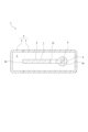
- the vehicular lamp 1 includes a lamp housing 2 that is open from the front or from the front to the sides, and a cover 3 that closes the opening of the lamp housing 2 (see FIG. 1).
- the lamp housing 2 and the cover 3 constitute a lamp outer casing 4, and an internal space of the lamp outer casing 4 is formed as a lamp chamber 5.
- a plurality of light sources 6 mounted on a board (not shown) and a light guide 7 that guides light emitted from the light sources 6 are arranged in the lamp chamber 5 (see FIGS. 1 to 3). Note that in addition to the light source 6 and the light guide 7, various members such as an extension may be arranged in the lamp chamber 5.
- the light source 6 for example, a light emitting diode (LED) is used.
- a first light source 6A and a second light source 6B are provided.
- the light source 6 is located on the side of the light guide 7.
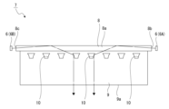
- the light guide 7 is composed of a linear light guide 8 extending in a predetermined direction, for example, the left-right direction, and a plate-shaped output part 9 that is continuous with the outer circumferential surface 8a of the light guide 8. and the emission section 9 are integrally formed of a transparent resin material or glass material.
- the cross-sectional shape of the light guide section 8 in the direction orthogonal to the longitudinal direction is, for example, circular, and is formed in the shape of a round shaft.
- the light guide portion 8 has a diameter of, for example, 4 mm or more.
- the light guide section 8 has one end surface in the longitudinal direction formed as a first entrance surface 8b, and the other end surface in the longitudinal direction formed as a second entrance surface 8c.
- the first entrance surface 8b is located facing the first light source 6A
- the second entrance surface 8c is located facing the second light source 6B.
- the light guide portion 8 is not formed with a step shape such as a reflective step.
- the shape of the light guide portion 8 is not limited to a round shaft shape, and the cross-sectional shape in the direction perpendicular to the longitudinal direction may be other shapes such as a rectangular shape or an elliptical shape.
- the cross-sectional shape of the light guide section 8 in the direction orthogonal to the longitudinal direction is formed into a circular shape, the shape of the light guide section 8 does not become an angular shape, and the first incident surface 8b and the second incident surface It becomes possible to increase the area of the surface 8c without excessively enlarging the outer shape, and it is possible to improve the light incidence efficiency while forming the light guide portion 8 in a simple shape.
- the light guide section 8 when light is guided by the light guide section 8, if there is a possibility that light that does not enter the output section 9 from the light guide section 8 may be emitted as leakage light, at least a part of the light guide section 8 may be extended. It is also possible to cover the light with a cover, etc., to prevent leakage of light.
- the emission part 9 is continuous with a part of the outer peripheral surface 8a of the light guide part 8.
- the emission part 9 is formed into a flat plate shape, for example, a rectangular shape, and one long side is continuous with the outer circumferential surface 8a of the light guide part 8.
- the thickness T of the emission part 9 is smaller than the width H of the light guide part 8 in the vertical direction (see FIG. 2). Therefore, the width H of the light guide section 8 in the same direction as the thickness direction of the emission section 9 is made larger than the thickness T of the emission section 9.
- the distal end surface of the emission part 9 is formed, for example, as a planar emission surface 9a facing forward (see FIGS. 2 and 3).
- the emission surface 9a has a vertical width of, for example, about 2 mm to 3 mm, and the light guided by the light guide section 8 is emitted from the emission surface 9a.
- the output surface 9a of the output section 9 may be formed in a curved shape that is convex toward the front when viewed from the vertical direction, or may be formed in a curved shape that is convex toward the front when viewed from the left and right directions. Good too.
- the output surface 9a of the output section 9 may be formed in a curved shape concave to the front when viewed from the vertical direction, or may be formed to have a curved shape concave to the front when viewed from the left and right directions. Good too.
- a lens step may be formed on the exit surface 9a.
- the design of the exit surface 9a when viewed from the outside through the cover 3 is enhanced, and visibility can be improved. Further, it is also possible to form a lens step on the output surface 9a or perform a predetermined processing so that the light emitted from the output surface 9a is emitted in a diffused state.
- the light control part formed on the upper surface or the lower surface of the emission part 9 can be controlled by the cover 3. It is also possible to ensure design quality by making it visible from the outside through.
- a plurality of light control parts 10 are formed in the emission part 9, and the light control part 10 is formed, for example, as a groove opened upward or downward (control groove) or a hole penetrated vertically (control hole). There is.
- the plurality of light control sections 10 are formed near the light guide section 8 and are spaced apart along the longitudinal direction of the light guide section 8 .
- the light control section 10 is shown as a control hole to simplify the explanation.
- the width of the emission part 9 in the front-rear direction can be set to any size depending on the size of the lamp chamber 5 and the relationship with other members arranged in the lamp chamber 5.
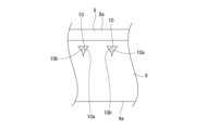
- the light control unit 10 has a circumferential surface formed by four surfaces: a first control surface 10a and a second control surface 10b separated from each other left and right, a third surface 10c facing rearward, and a third surface facing forward.
- a surface 10d of No. 4 is formed (see FIG. 4).
- the first control surface 10a and the second control surface 10b are formed into curved surfaces that are inclined so as to approach each other as they approach the exit surface 9a from the light guide section 8, and are convex in the direction in which they approach each other.
- the left and right ends of the third surface 10c are continuous with the front ends of the first control surface 10a and the second control surface 10b, respectively, and the left and right ends of the fourth surface 10d are continuous with the front ends of the first control surface 10a and the second control surface 10b, respectively. It is continuous with each rear end of the control surface 10b.
- the first control surface 10a and the second control surface 10b have a function of controlling the light guided by the light guide section 8.
- the light incident on the control surface 10b is totally reflected by the first control surface 10a and the second control surface 10b, respectively, and heads toward the output surface 9a.
- first control surface 10a and the second control surface 10b may be formed in a curved shape, a planar shape, or a shape in which a diffusion step is formed.
- the diffusion step By forming the diffusion step on the first control surface 10a and the second control surface 10b, the light emitted from the output surface 9a is diffused, and uniformity of the light can be ensured.
- first control surface 10a and the second control surface 10b are formed in the light control section 10, and the first control surface 10a and the second control surface 10b are connected to the exit surface 9a from the light guide section 8. They are tilted so that they approach each other as they get closer to each other.
- the light control section 10 is formed by each surface including the first control surface 10a and the second control surface 10b that are inclined toward each other, it is easy to form the light control section 10, and the manufacturing cost is reduced. It is possible to individually control the light emitted from the plurality of light sources 6 without causing a rise in the amount of light.
- the surfaces forming the light control section 10 are a first control surface 10a, a second control surface 10b, a third surface 10c, and a fourth surface 10d.
- the light control section 10 is formed by the first control surface 10a, the second control surface 10b, the third surface 10c, and the fourth surface 10d, the formation of the light control section 10 is easy, and the light
- the control unit 10 is formed in a simple shape, and can control each of the lights emitted from the plurality of light sources 6 with a simple configuration without increasing manufacturing costs. Furthermore, since the light control section 10 is formed into a rectangular shape, the corners of the shape are unlikely to have acute angles, making it easy to process and making it possible to form the light control section 10 with high processing accuracy.
- the plurality of light control units 10 may have the same size or may have different sizes.
- each light control part 10 is made so that the areas of the first control surface 10a and the second control surface 10b increase as the distance from the exit surface 9a increases. The size may be determined. Since the light guided by the light guide section 8 is attenuated as it goes away from the output surface 9a, with this configuration, the light is incident on all the first control surfaces 10a and the second control surfaces 10b. It becomes possible to make the amount of light constant, and it becomes possible to achieve uniformity in the brightness of the light emitted from the emission surface 9a.
- the shape of the light control section 10 is not limited to a rectangular shape, and may be formed in other shapes such as a triangular shape (see FIG. 5).
- the light control section 10 has a triangular shape, for example, the light control section 10 is formed in a triangular shape convex toward the front, and the left and right surfaces are a first control surface 10a and a second control surface 10b, respectively. be done.
- the vehicle lamp 1 when light is emitted from the first light source 6A, the emitted light enters from the first entrance surface 8b and is guided by the light guide section 8.
- the light guided by the light section 8 is respectively incident on the plurality of first control surfaces 10a (see FIG. 3).
- the light incident on the first control surface 10a is totally reflected by the first control surface 10a and is controlled and directed toward the emission surface 9a, and is emitted from the emission surface 9a, transmitted through the cover 3, and directed to the outside. irradiated.
- light is also emitted from the second light source 6B at the same time.
- the emitted light enters from the second incident surface 8c and is guided by the light guide section 8, and the light guided by the light guide section 8 is transmitted to each of the plurality of light guide sections 8.
- the light is incident on the control surface 10b of No.2.
- the light incident on the second control surface 10b is totally reflected by the second control surface 10b and is controlled and directed toward the output surface 9a, and is emitted from the output surface 9a, transmitted through the cover 3, and directed to the outside. irradiated.
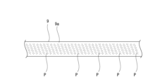
- the light is controlled by each of the first control surfaces 10a and each of the second control surfaces 10b, and each of the controlled lights is visually recognized as a thin line of light emitting portions from the output surface 9a, and a plurality of light emitting portions P, P, . . . are arranged in close proximity to each other (see FIG. 6).
- the emission surface 9a is formed in an elongated shape in the left-right direction, the light-emitting state seen through the cover 3 by the viewer is one horizontally long line where the light-emitting portions P, P,... It is visually recognized as a light emitting state.
- the light emitting portion P shown in FIG. 6 is inclined in a predetermined direction with respect to the vertical direction, but the direction and angle of this inclination depend on the shapes and orientations of the first control surface 10a and the second control surface 10b, etc. It is possible to set it arbitrarily.
- the light guide part 8 is formed in a linear shape and the output part 9 is formed in a flat plate shape facing in the vertical direction. It may be formed in a different shape.
- the light guide part 8 and the light emitting part 9 are formed in a bent or curved shape in this way, the light guide part 8 and the light emitting part 9 are formed into a shape that corresponds to the overall shape of the vehicle body and the vehicle lamp 1. This makes it possible to reduce the size of the vehicular lamp 1 by increasing the degree of freedom in design.
- the light guide section 8 when the light guide section 8 is formed in a straight line shape and the output section 9 is formed in a flat plate shape, the light guide section 8 and the output section 9 are formed in a simple shape and a shape that facilitates light control. The structure is simplified and light can be easily controlled.
- the width H of the light guide section 8 in the same direction as the thickness direction of the output section 9 is larger than the thickness T of the output section 9, and the light control section 10 is formed.
- Each part of the circumferential surface is formed as a control surface that controls the light to go toward the output surface 9a, and the light emitted from different light sources 6 and guided by the light guide section 8 is transmitted to a different control surface in the light control section 10.
- Each is controlled separately by
- each light guided by the light guide section 8 whose width H is larger than the thickness T of the output section 9 is controlled by different control surfaces in the light control section 10 and is emitted from the output surface 9a of the output section 9. Therefore, the amount of light emitted from each light source 6 is incident on the incident surface, increasing the efficiency of light use, realizing a narrower light emission state, and creating an appropriate light distribution pattern. can be formed.
- one end surface in the longitudinal direction of the light guide section 8 is formed as a first entrance surface 8b
- the other end surface in the longitudinal direction of the light guide section 8 is formed as a second entrance surface 8c
- the first end surface in the longitudinal direction of the light guide section 8 is formed as a first entrance surface 8b.
- a first light source 6A that emits light incident thereon and a second light source 6B that emits light incident from the second entrance surface 8c are provided.
- the light emitted from the first light source 6A and the second light source 6B is controlled separately by the first control surface 10a and the second control surface 10b, the light emitted from the first light source 6A and the second light source 6B is controlled separately, so that the desired light can be obtained while increasing the light emission efficiency. It is possible to emit light in a direction.
- each modification of the light guide shown below has the same basic structure as the light guide 7 described above, so symbols such as A, B, etc. are attached to each code to indicate the light guide.
- symbols such as A, B, etc. are attached to each code to indicate the light guide. The parts that are different from body 7 will be explained.
- the light guide 7A according to the first modification includes a first light guide section 8X, a second light guide section 8Y, and an output section 9 (see FIG. 7).
- the first light guide section 8X is formed, for example, in a linear shape, and one end surface is formed as the entrance surface 8d.
- the second light guide section 8Y is formed, for example, in a linear shape, and one end surface is formed as the entrance surface 8e.
- the second light guide section 8Y is parallel to the first light guide section 8X and is located on the opposite side of the output section 9 with the first light guide section 8X in between.
- the outer peripheral surfaces 8a of the first light guide section 8X and the second light guide section 8Y are connected to each other by a coupling section 11.
- the other end surface in the longitudinal direction of the first light guide section 8X and the other end surface in the longitudinal direction of the second light guide section 8Y are connected by a semicircular arc-shaped light guide connecting section 12.
- a first light source 6A is arranged at a position facing the entrance surface 8d of the first light guide 8X, and a second light source 6B is arranged at a position opposite the entrance surface 8e of the second light guide 8Y. has been done.
- the first light source 6A and the second light source 6B may emit light of the same color, or may emit light of different colors.
- the light guide 7A configured as described above
- the emitted light enters from the entrance surface 8d and enters the first guide.
- the light guided by the light section 8X and guided by the first light guide section 8X is incident on the plurality of first control surfaces 10a.
- the light incident on the first control surface 10a is totally reflected by the first control surface 10a and is controlled and directed toward the emission surface 9a, and is emitted from the emission surface 9a, transmitted through the cover 3, and directed to the outside. irradiated.
- light is also emitted from the second light source 6B.
- the emitted light enters from the entrance surface 8e and is guided by the second light guide section 8Y, and is sequentially connected to the light guide connecting section 12 and the first light guide section. 8X and enters the plurality of second control surfaces 10b.
- the light incident on the second control surface 10b is totally reflected by the second control surface 10b and is controlled and directed toward the output surface 9a, and is emitted from the output surface 9a, transmitted through the cover 3, and directed to the outside. irradiated.
- the light guide 7A is provided with the first light guide section 8X and the second light guide section 8Y, and the other end surface in the longitudinal direction of the first light guide section 8X and the second light guide section 8Y are provided.
- the other end surface in the longitudinal direction is connected by the light guide connecting part 12, and the light guided by the second light guide part 8Y is guided from the light guide connecting part 12 to the first light guide part 8X.
- the first light source 6A and the second light source It becomes easier for light to enter the light guide 7A from the light guide 6B, and it is possible to improve the efficiency of light incidence into the light guide 7A.
- the light guided by the second light guide section 8Y is guided from the light guide connecting section 12 to the first light guide section 8X, and the light emitted from the first light source 6A and the second light source 6B is Since each light is controlled individually by different control surfaces, it is possible to emit light in a desired direction while increasing emission efficiency.
- the light from the first light source 6A and the second light source 6B is Since the incident efficiency of the light becomes high, it is possible to reliably emit the mixed light of the desired color.
- the number of light guide parts 8 in 7 A of light guides is There may be three or more.
- the light sources 6 are arranged opposite to each incident surface of each light guide section 8 .
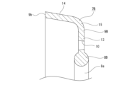
- the light guide 7B according to the second modification has a light guide section 8B and an output section 9 (see FIGS. 8 and 9).
- the light guide portion 8B is formed in a curved shape, for example, an arc shape, and one end surface in the longitudinal direction is formed as a first entrance surface 8b, and the other end surface in the longitudinal direction is formed as a second entrance surface 8c.
- the first entrance surface 8b is located facing the first light source 6A
- the second entrance surface 8c is located facing the second light source 6B.
- the output portion 9B is formed in a shape that extends in the circumferential direction as a whole in correspondence with the light guide portion 8B, and is bent at an intermediate portion in the direction of protrusion from the light guide portion 8B.
- the output section 9B is composed of a first section 13 continuous to the light guide section 8B and a second section 14 continuous to the first section 13.
- the first portion 13 and the second portion 14 are formed in substantially perpendicular shapes, and the distal end surface of the second portion 14 is formed as an output surface 9b facing substantially forward.
- a continuous portion 15 of the first portion 13 and the second portion 14 is formed in a curved shape.
- the vehicle lamp 1 having the light guide body 7B configured as described above, when light is emitted from the first light source 6A, the emitted light enters from the first entrance surface 8b and enters the light guide part. 8B, and the light guided by the light guide portion 8B is incident on the plurality of first control surfaces 10a, respectively.
- the light incident on the first control surface 10a is totally reflected by the first control surface 10a and is controlled and directed toward the output surface 9a, and is emitted from the output surface 9a, transmitted through the cover 3, and directed to the outside. irradiated.
- light is also emitted from the second light source 6B.
- the emitted light enters the second entrance surface 8c and is guided by the light guide section 8B, and the light guided by the light guide section 8B is transmitted to each of the plurality of light guide sections 8B.
- the light is incident on the control surface 10b of No.2.
- the light incident on the second control surface 10b is totally reflected by the second control surface 10b and is controlled and directed toward the output surface 9a, and is emitted from the output surface 9a, transmitted through the cover 3, and directed to the outside. irradiated.
- the output surface 9b of the output part 9B is formed in a curved shape, so that the light can be adjusted to a desired shape according to the overall shape of the vehicle body and the vehicle lamp 1. It is now possible to emit light from the region of , which increases the degree of freedom in design and improves visibility.
- the light guide 7B has a curved portion 15 of the output portion 9B, the light is easily totally reflected at the portion 15, and the light controlled by the light control portion 10 does not reach the output surface 9b. It is possible to easily improve the light output efficiency.
- parts other than the second part 14 are covered from the front side with an extension to prevent leakage light from being emitted to the front and to improve visibility when viewed from the outside. You can do it like this.
- SYMBOLS 1 Vehicle lamp, 6... Light source, 6A... First light source, 6B... Second light source, 7... Light guide, 8... Light guide part, 8a... Outer peripheral surface, 8b... First incident surface, 8c ...Second entrance surface, 9...Emission section, 9a...Emission surface, 10...Light control section, 10a...First control surface, 10b...Second control surface, 10c...Third surface, 10d...Fourth surface, 7A...light guide, 8X...first light guide, 8d...incident surface, 8Y...second light guide, 8e...incident surface, 12...light guide coupling part, 7B...light guide , 8B...Light guide part, 9B...Emission part
Landscapes
- Engineering & Computer Science (AREA)
- General Engineering & Computer Science (AREA)
- Physics & Mathematics (AREA)
- Optics & Photonics (AREA)
- General Physics & Mathematics (AREA)
- Microelectronics & Electronic Packaging (AREA)
- Non-Portable Lighting Devices Or Systems Thereof (AREA)
Priority Applications (1)
| Application Number | Priority Date | Filing Date | Title |
|---|---|---|---|
| JP2024535029A JPWO2024018939A1 (https=) | 2022-07-20 | 2023-07-10 |
Applications Claiming Priority (2)
| Application Number | Priority Date | Filing Date | Title |
|---|---|---|---|
| JP2022-115389 | 2022-07-20 | ||
| JP2022115389 | 2022-07-20 |
Publications (1)
| Publication Number | Publication Date |
|---|---|
| WO2024018939A1 true WO2024018939A1 (ja) | 2024-01-25 |
Family
ID=89617862
Family Applications (1)
| Application Number | Title | Priority Date | Filing Date |
|---|---|---|---|
| PCT/JP2023/025407 Ceased WO2024018939A1 (ja) | 2022-07-20 | 2023-07-10 | 車輌用灯具 |
Country Status (2)
| Country | Link |
|---|---|
| JP (1) | JPWO2024018939A1 (https=) |
| WO (1) | WO2024018939A1 (https=) |
Citations (3)
| Publication number | Priority date | Publication date | Assignee | Title |
|---|---|---|---|---|
| JP2012532339A (ja) * | 2009-06-29 | 2012-12-13 | スリーエム イノベイティブ プロパティズ カンパニー | ライトガイド及び該ライトガイドが組み込まれた光源 |
| JP2020031016A (ja) * | 2018-08-24 | 2020-02-27 | 株式会社小糸製作所 | 車両用灯具 |
| JP2020095782A (ja) * | 2018-12-10 | 2020-06-18 | 株式会社小糸製作所 | 車両用灯具 |
-
2023
- 2023-07-10 WO PCT/JP2023/025407 patent/WO2024018939A1/ja not_active Ceased
- 2023-07-10 JP JP2024535029A patent/JPWO2024018939A1/ja active Pending
Patent Citations (3)
| Publication number | Priority date | Publication date | Assignee | Title |
|---|---|---|---|---|
| JP2012532339A (ja) * | 2009-06-29 | 2012-12-13 | スリーエム イノベイティブ プロパティズ カンパニー | ライトガイド及び該ライトガイドが組み込まれた光源 |
| JP2020031016A (ja) * | 2018-08-24 | 2020-02-27 | 株式会社小糸製作所 | 車両用灯具 |
| JP2020095782A (ja) * | 2018-12-10 | 2020-06-18 | 株式会社小糸製作所 | 車両用灯具 |
Also Published As
| Publication number | Publication date |
|---|---|
| JPWO2024018939A1 (https=) | 2024-01-25 |
Similar Documents
| Publication | Publication Date | Title |
|---|---|---|
| JP7278920B2 (ja) | 導光レンズ、レンズ結合体及び車両用灯具 | |
| JP2012119199A (ja) | 車両用灯具 | |
| JP2004103503A (ja) | 導光体及びこの導光体を有する車両用灯具 | |
| CN115667794A (zh) | 车辆用灯具 | |
| JP7265437B2 (ja) | 車両用灯具 | |
| JP6814070B2 (ja) | 車両用灯具 | |
| US20250216049A1 (en) | Vehicle lamp | |
| JP6887257B2 (ja) | 車両用灯具 | |
| JP7788920B2 (ja) | 車両用灯具 | |
| JP2018026192A (ja) | 車両用灯具 | |
| WO2024018939A1 (ja) | 車輌用灯具 | |
| KR20180100758A (ko) | 차량용 램프 | |
| JP2025133395A (ja) | 車両用灯具 | |
| WO2023210343A1 (ja) | 車両用灯具 | |
| JP7554101B2 (ja) | 車両用灯具 | |
| WO2022004287A1 (ja) | 車輌用灯具 | |
| JP2023000113A (ja) | 車両用灯具 | |
| JP7764213B2 (ja) | 車両用灯具 | |
| JP7756044B2 (ja) | 車両用灯具 | |
| JP7840818B2 (ja) | 車両用灯具 | |
| JP7792229B2 (ja) | 車両用灯具 | |
| JP7579723B2 (ja) | 車両用灯具 | |
| WO2025192333A1 (ja) | 車輌用灯具 | |
| JP2025022357A (ja) | 車輌用灯具 | |
| JP7417412B2 (ja) | 車両用灯具 |
Legal Events
| Date | Code | Title | Description |
|---|---|---|---|
| 121 | Ep: the epo has been informed by wipo that ep was designated in this application |
Ref document number: 23842864 Country of ref document: EP Kind code of ref document: A1 |
|
| WWE | Wipo information: entry into national phase |
Ref document number: 2024535029 Country of ref document: JP |
|
| NENP | Non-entry into the national phase |
Ref country code: DE |
|
| 122 | Ep: pct application non-entry in european phase |
Ref document number: 23842864 Country of ref document: EP Kind code of ref document: A1 |