WO2024018820A1 - モータ及び天井扇 - Google Patents
モータ及び天井扇 Download PDFInfo
- Publication number
- WO2024018820A1 WO2024018820A1 PCT/JP2023/023212 JP2023023212W WO2024018820A1 WO 2024018820 A1 WO2024018820 A1 WO 2024018820A1 JP 2023023212 W JP2023023212 W JP 2023023212W WO 2024018820 A1 WO2024018820 A1 WO 2024018820A1
- Authority
- WO
- WIPO (PCT)
- Prior art keywords
- rotor
- hall
- motor
- stator
- electromagnets
- Prior art date
- Legal status (The legal status is an assumption and is not a legal conclusion. Google has not performed a legal analysis and makes no representation as to the accuracy of the status listed.)
- Ceased
Links
Images


Classifications
-
- H—ELECTRICITY
- H02—GENERATION; CONVERSION OR DISTRIBUTION OF ELECTRIC POWER
- H02K—DYNAMO-ELECTRIC MACHINES
- H02K1/00—Details of the magnetic circuit
- H02K1/06—Details of the magnetic circuit characterised by the shape, form or construction
- H02K1/22—Rotating parts of the magnetic circuit
- H02K1/27—Rotor cores with permanent magnets
- H02K1/2793—Rotors axially facing stators
- H02K1/2795—Rotors axially facing stators the rotor consisting of two or more circumferentially positioned magnets
- H02K1/2798—Rotors axially facing stators the rotor consisting of two or more circumferentially positioned magnets where both axial sides of the stator face a rotor
-
- H—ELECTRICITY
- H02—GENERATION; CONVERSION OR DISTRIBUTION OF ELECTRIC POWER
- H02K—DYNAMO-ELECTRIC MACHINES
- H02K11/00—Structural association of dynamo-electric machines with electric components or with devices for shielding, monitoring or protection
- H02K11/20—Structural association of dynamo-electric machines with electric components or with devices for shielding, monitoring or protection for measuring, monitoring, testing, protecting or switching
- H02K11/21—Devices for sensing speed or position, or actuated thereby
- H02K11/215—Magnetic effect devices, e.g. Hall-effect or magneto-resistive elements
-
- H—ELECTRICITY
- H02—GENERATION; CONVERSION OR DISTRIBUTION OF ELECTRIC POWER
- H02K—DYNAMO-ELECTRIC MACHINES
- H02K16/00—Machines with more than one rotor or stator
- H02K16/02—Machines with one stator and two or more rotors
-
- H—ELECTRICITY
- H02—GENERATION; CONVERSION OR DISTRIBUTION OF ELECTRIC POWER
- H02K—DYNAMO-ELECTRIC MACHINES
- H02K21/00—Synchronous motors having permanent magnets; Synchronous generators having permanent magnets
- H02K21/12—Synchronous motors having permanent magnets; Synchronous generators having permanent magnets with stationary armatures and rotating magnets
- H02K21/24—Synchronous motors having permanent magnets; Synchronous generators having permanent magnets with stationary armatures and rotating magnets with magnets axially facing the armatures, e.g. hub-type cycle dynamos
Definitions
- the present disclosure relates to a motor and a ceiling fan, and more particularly, to a so-called axial gap type motor and a ceiling fan using the motor as a power source.
- an axial gap type rotating electrical machine (motor) described in Patent Document 1 is illustrated.
- the axial gap type rotating electrical machine described in Patent Document 1 (hereinafter referred to as a conventional example) includes a stator and a pair of rotors.
- the stator has a plurality of stator cores and a plurality of coils formed by winding conductive wire around each stator core. These plurality of stator cores are arranged at equal intervals along the circumferential direction of the rotating shaft.
- the pair of rotors are attached to the rotating shaft so as to sandwich the stator in the axial direction of the rotating shaft.
- Each rotor includes a disk-shaped back yoke and a plurality of permanent magnets arranged on a surface of the back yoke facing the stator.
- the plurality of permanent magnets are fixed to the back yoke so as to be arranged at equal intervals along the circumferential direction of the rotating shaft.
- conventional brushless motors usually use a Hall element to detect the magnetic field (magnetic flux) of a permanent magnet in order to determine the timing of passing excitation current through a plurality of electromagnets (coils).
- a Hall element (or a Hall IC in which a Hall element and a signal processing circuit are integrated) is mounted on a printed wiring board and placed at a position where the magnetism (magnetic flux) of a permanent magnet can be detected.
- An object of the present disclosure is to provide a motor and a ceiling fan that can suppress deterioration in accuracy of magnetic detection.
- a motor includes a stator and a rotor that is rotatable with respect to the stator.
- the rotor includes permanent magnets in which different magnetic poles are arranged alternately along the rotation direction, and a support member that supports the permanent magnets.
- the stator includes a plurality of electromagnets arranged along the rotational direction of the rotor, a mounting member to which the plurality of electromagnets are attached, and a magnetic detection section that detects magnetism of the permanent magnet.
- Each of the plurality of electromagnets has a stator core and a coil wound around the stator core.
- the magnetic detection section includes a Hall element or a Hall IC, and a support substrate that supports the Hall element or the Hall IC.
- the Hall element or the Hall IC is arranged outside the stator core with respect to the rotation center of the rotor.
- a ceiling fan includes the motor and one or more blades that are driven and rotated by the motor.
- FIG. 1 is an exploded perspective view of a motor according to an embodiment of the present disclosure.
- FIG. 2 is a perspective view of the same motor with the connecting body omitted.
- FIG. 3 is a side view of the same motor with the connecting body omitted.
- FIG. 4 is a perspective view of the same motor with the connecting body and second rotor omitted.
- FIG. 5 is a perspective view of the same motor with the connecting body, second rotor, and mounting plate omitted.
- FIG. 6 is a plan view of the same motor with the connecting body and support member omitted.
- FIG. 7 is a plan view of the same motor with the connecting body, support member, and permanent magnet omitted.
- FIG. 1 is an exploded perspective view of a motor according to an embodiment of the present disclosure.
- FIG. 2 is a perspective view of the same motor with the connecting body omitted.
- FIG. 3 is a side view of the same motor with the connecting body omitted.
- FIG. 4 is a
- FIG. 8 is a plan view of the main parts of the same motor with the connecting body, support member, and permanent magnet omitted.
- FIG. 9 is an explanatory diagram for explaining the operation of the motor same as above.
- FIG. 10 is an explanatory diagram for explaining the operation of the motor same as above.
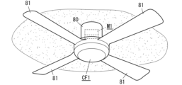
- FIG. 11 is a perspective view of a ceiling fan according to an embodiment of the present disclosure.
- the motor M1 includes a stator S1 and a rotor (first rotor R1) that is rotatable with respect to the stator S1 (see FIGS. 1 to 3).
- the first rotor R1 includes a permanent magnet 4 in which different magnetic poles (magnetic pole portions 40) are arranged alternately along the rotation direction, and a support member 5 that supports the permanent magnet 4.
- the stator S1 includes a plurality of electromagnets 1 arranged along the rotational direction of the first rotor R1, a mounting member 2 to which the plurality of electromagnets 1 are attached, and a magnetic detection section 3 that detects the magnetism of the permanent magnet 4. .
- Each of the plurality of electromagnets 1 has a stator core 10 and a coil 11 wound around the stator core 10.
- the magnetic detection unit 3 includes a Hall element or Hall IC 30 and a support substrate 31 that supports the Hall IC 30.
- Hall IC 30 is arranged outside stator core 10 with respect to the rotation center of first rotor R1 (center of shaft 6) (see FIG. 7).
- the Hall element or Hall IC 30 when the Hall element or Hall IC 30 is arranged inside the stator core 10 with respect to the rotation center of the first rotor R1, the Hall element or the Hall IC 30 is The gap between the Hall IC 30 and the permanent magnet 4 becomes wider, which may lead to a decrease in the accuracy of magnetic detection by the magnetic detection section 3.
- the Hall element or Hall IC 30 is arranged outside the stator core 10 with respect to the rotation center of the first rotor R1 (the center of the shaft 6). Therefore, in the motor M1 according to the embodiment, the accuracy of magnetic detection is reduced due to the deflection of the support substrate 31, compared to the case where the Hall element or the Hall IC 30 is arranged inside the stator core 10 with respect to the rotation center of the first rotor R1. can be suppressed.
- the ceiling fan CF1 includes a motor M1 according to the embodiment of the present disclosure, and one or more blades 81 that are driven and rotated by the motor M1.
- the ceiling fan CF1 according to the embodiment includes the motor M1 according to the embodiment of the present disclosure, it is possible to suppress a decrease in accuracy of magnetic detection.
- the motor M1 (hereinafter abbreviated as motor M1) according to the embodiment includes a rotor block and a stator S1.
- the motor M1 further includes a shaft 6 that rotatably supports the rotor block (see FIGS. 1 to 3).
- the shaft 6 is formed of a metal material into a hollow cylindrical shape.
- the rotor block has a first rotor R1, a second rotor R2, and a connecting body W1 that connects the first rotor R1 and the second rotor R2 (see FIG. 1). ).
- the first rotor R1 includes a permanent magnet 4 and a support member 5 that supports the permanent magnet 4.
- the permanent magnet 4 is, for example, a ring-shaped neodymium magnet with multiple poles on both sides. That is, the permanent magnet 4 has a plurality of magnetic pole parts 40 that are magnetized to have different poles (N pole and S pole) in the thickness direction. These plurality of magnetic pole parts 40 have the same shape and the same size, and are arranged so that different poles are alternately lined up along the circumferential direction of the permanent magnet 4 (see FIG. 1). Although the number of magnetic pole parts 40 in the embodiment is 18, it is not limited to this, and may be from 2 to 17 or 19 or more. Furthermore, the permanent magnet 4 may be a magnet other than a neodymium magnet, such as a ferrite magnet or a samarium cobalt magnet.
- the support member 5 has a bottom wall 50, a peripheral wall 51, a flange 52, and a housing portion 53 (see FIGS. 1 to 5). Note that it is preferable that the bottom wall 50, the peripheral wall 51, the flange 52, and the accommodating portion 53 be integrally formed of a soft magnetic material such as stainless steel.
- the bottom wall 50 is formed into a disk shape.
- the peripheral wall 51 is formed in a cylindrical shape and protrudes from the peripheral edge of the bottom wall 50 in the thickness direction of the bottom wall 50.
- the flange 52 is formed in a ring shape and protrudes outward from the tip of the peripheral wall 51.
- the accommodating portion 53 is formed into a cylindrical shape with a bottom. The accommodating portion 53 protrudes from the center of the bottom wall 50 along the thickness direction of the bottom wall 50 in a direction opposite to the peripheral wall 51 (downward in FIG. 1).
- a circular hole 530 passes through the bottom of the housing portion 53 (see FIG. 1).
- a bearing is housed in the housing portion 53.
- the support member 5 (first rotor R1) is rotatably supported by the shaft 6 via a bearing housed in the housing section 53.
- the permanent magnet 4 is fixed to the bottom wall 50 by an appropriate method such as adhesion, welding, caulking, or screwing. That is, the permanent magnet 4 is housed in a space surrounded by the bottom wall 50 and the peripheral wall 51 (see FIG. 2).
- the second rotor R2 has a top plate 70, a side plate 71, a flange 72, and a housing portion 73.
- the top plate 70, the side plate 71, the flange 72, and the accommodating part 73 be integrally formed of a soft magnetic material such as stainless steel.
- the top plate 70 is formed into a disk shape.
- the side plate 71 is formed in a cylindrical shape and protrudes from the periphery of the top plate 70 in the thickness direction of the top plate 70.
- the flange 72 is formed in a ring shape and protrudes outward from the tip of the side plate 71.
- the housing portion 73 is formed into a cylindrical shape with a bottom. The housing portion 73 protrudes from the center of the top plate 70 along the thickness direction of the top plate 70 in a direction opposite to the side plate 71 (upward in FIG. 1).
- a circular hole 730 passes through the bottom of the accommodating portion 73.
- a bearing is housed in the housing portion 73.
- the second rotor R2 is rotatably supported by the shaft 6 via a bearing housed in the housing portion 73.
- the connecting body W1 is formed into a cylindrical shape from a soft magnetic material such as stainless steel.
- the flange 52 of the support member 5 of the first rotor R1 is screwed (or riveted) to the first end surface (the lower end surface in FIG. 1) of the coupling body W1.
- the flange 72 of the second rotor R2 is screwed (or riveted) to the second end surface (the upper end surface in FIG. 1) of the coupling body W1. That is, the first rotor R1 (support member 5) and the second rotor R2 are connected by the connecting body W1 and can rotate integrally.
- the stator S1 includes a plurality of electromagnets 1 arranged along the rotation direction of the rotor block, a mounting member 2 to which the plurality of electromagnets 1 are attached, and a magnetic detection section 3 that detects the magnetism of the permanent magnet 4. , has.
- Electromagnet The plurality of electromagnets 1 all have the same configuration. Note that the number of the plurality of electromagnets 1 is the same as the number of the plurality of magnetic pole parts 40 of the permanent magnet 4 (18 pieces). However, the number of electromagnets 1 may not be the same as the number of magnetic pole parts 40.
- the electromagnet 1 includes a stator core 10, a coil 11, and a bobbin 12.
- the stator core 10 includes a first flange 101, a second flange 102, a fixed part 103, and a body (see FIG. 5).
- the first flange 101 and the second flange 102 are each formed into a rectangular flat plate shape.
- the body is formed into a prismatic shape and connects the first flange 101 and the second flange 102.
- the fixing portion 103 is formed into a rectangular flat plate shape.
- the fixing part 103 is coupled to the second flange 102 so that a part thereof overlaps a part of the second flange 102 in the thickness direction (see FIG. 5). Note that two protrusions 105 are provided on the surface of the fixing part 103.
- These two protrusions 105 are formed in the shape of a square column and protrude from the surface of the fixing part 103 so as to be lined up parallel to each other.
- the first flange 101, the second flange 102, the fixed part 103, and the body are preferably formed integrally by laminating a plurality of laminated steel plates made of a soft magnetic material such as electromagnetic steel plates in one direction. .
- the bobbin 12 has a cylindrical winding trunk through which the body of the stator core 10 is inserted, and a pair of flanges 121 provided at both ends of the winding trunk in the axial direction.
- the pair of flange portions 121 are formed in an elliptical shape and protrude outward from each end of the winding drum portion in the axial direction.
- the winding trunk portion and the pair of flange portions 121 are integrally formed of an electrically insulating material such as synthetic resin.
- the bobbin 12 is composed of two parts in consideration of ease of assembly.
- the coil 11 is constructed by winding a wire rod made of aluminum or aluminum alloy around the body of the stator core 10 from above the winding body of the bobbin 12 .
- the mounting member 2 includes a mounting plate 20, a plurality of fixing members 21, and a reinforcing member 22.
- the mounting plate 20 is formed into a disc shape from a soft magnetic material such as stainless steel.
- a D-shaped insertion hole 200 passes through the center of the mounting plate 20.
- the shaft 6 is inserted through the insertion hole 200.
- the mounting plate 20 has a plurality of first mounting holes 201, a plurality of second mounting holes 202, and a plurality of third mounting holes 203 (see FIG. 1).
- the plurality of first mounting holes 201 are each circular and are arranged at equal intervals along the circumferential direction of the mounting plate 20 at both ends of the mounting plate 20 in the radial direction.
- the plurality of second mounting holes 202 are each rectangular, and are lined up along the circumferential direction of the mounting plate 20 inside the plurality of first mounting holes 201 at both ends of the mounting plate 20 in the radial direction.
- the plurality of third mounting holes 203 are each circular, and are arranged at equal intervals along the circumferential direction of the mounting plate 20 inside the plurality of second mounting holes 202 at both ends of the mounting plate 20 in the radial direction. There is.
- the plurality of fixing members 21 all have the same configuration. Note that the number of the plurality of fixing members 21 is the same as that of the electromagnets 1 (18 pieces). However, the number of fixing members 21 may not be the same as the number of electromagnets 1.
- the fixing member 21 is formed into a wedge shape from a non-magnetic material such as synthetic resin.
- a recess 210 is formed in the first surface of the fixing member 21 (the surface facing the mounting plate 20). Furthermore, one through hole 211 and one through hole 212 are provided at both longitudinal ends of the fixing member 21, each penetrating in the height direction of the fixing member 21 (see FIG. 5).
- the reinforcing member 22 has a cylindrical main body portion 220, a tube portion 221, and a plurality of prismatic protrusions 222 (see FIGS. 1 and 5). Note that it is preferable that the main body portion 220, the cylindrical portion 221, and the plurality of protrusions 222 be integrally formed of a non-magnetic material such as synthetic resin or aluminum.
- a D-shaped insertion hole passes through the center of the main body portion 220.
- the cylindrical portion 221 protrudes from the periphery of the insertion hole on the first surface (lower surface in FIG. 1) of the main body portion 220 in the normal direction of the first surface (downward in FIG. 1). Note that the cylindrical portion 221 is formed into a cylindrical shape whose cross-sectional shape parallel to the first surface has the same shape as the insertion hole.
- Each of the plurality of protrusions 222 protrudes from the first surface of the main body portion 220 in the same direction as the cylindrical portion 221. Further, the plurality of protrusions 222 are arranged at equal intervals in the circumferential direction at both radial ends of the main body portion 220. Furthermore, a through hole 224 that penetrates the protrusion 222 in the height direction (vertical direction in FIG. 1) is provided at the outer end of each protrusion 222 (see FIG. 5). Note that the number of the plurality of protrusions 222 is the same as that of the electromagnets 1 (18 pieces), but the number does not have to be the same as that of the electromagnets 1.
- the main body portion 220 is provided with a plurality of groove portions 223.
- the plurality of grooves 223 are arranged at equal intervals along the circumferential direction of the main body 220, spanning the second surface (the upper surface in FIG. 1) of the main body 220 and the side surface of the main body 220.
- the tip portions of the plurality of fixing members 21 are fitted into each of the plurality of grooves 223 one by one (see FIG. 5). That is, the number of the plurality of grooves 223 is the same as that of the fixing member 21 (18 pieces).
- the magnetic detection unit 3 includes a plurality of Hall ICs 30, a support substrate 31, and a holder 32 (see FIG. 1).
- Each of the plurality of (three in the illustrated example) Hall ICs 30 is configured by accommodating a Hall element for magnetic detection and a signal processing circuit in one package.
- the signal processing circuit performs signal processing on the output of the Hall element and outputs a detection signal.
- the detection signal output from the signal processing circuit (Hall IC 30) is a signal indicating the timing at which the direction of the magnetic field (magnetic flux) of the permanent magnet 4 is reversed as the rotor block rotates.
- the support substrate 31 has a mounting section 313, a protruding section 314, and a base section 315.
- the mounting portion 313 is formed into an arcuate flat plate shape.
- the three Hall ICs 30 are mounted on the first surface 311 (lower surface in FIG. 1) of the mounting portion 313 at equal intervals along the circumferential direction (see FIG. 7).
- the protrusion 314 is formed into a narrow rectangular shape.
- the tip of the protruding portion 314 is connected to the mounting portion 313.
- the base portion 315 is formed into a rectangular shape that is sufficiently wider than the protrusion portion 314.
- the base portion 315 is connected to the rear end of the protruding portion 314.
- a connector is mounted on the surface of the base portion 315 (the upper surface in FIG. 1).
- the connector is electrically connected to each Hall IC 30 via conductors (printed wiring) formed on the mounting portion 313, the protruding portion 314, and the base portion 315. That is, the detection signal output from each Hall IC 30 is output to an external drive device (driver circuit) via the connector.
- the holder 32 includes a first support part 321 that supports the mounting part 313, a second support part 322 that supports the protrusion part 314, a third support part 323 that supports the base part 315, and a mounting part 324.
- the first support part 321, the second support part 322, the third support part 323, and the attachment part 324 are integrally formed of a non-magnetic material such as synthetic resin (see FIGS. 1, 5, and 7). ).
- the first support portion 321 is formed into an arcuate frame shape.
- the first support portion 321 supports the periphery of the mounting portion 313 of the support substrate 31 (see FIG. 5).
- the second support portion 322 is formed into a long box shape.
- the tip of the second support part 322 is connected to the first support part 321.
- the second support portion 322 accommodates and supports the protrusion portion 314 of the support substrate 31 (see FIG. 5).
- the third support portion 323 is formed into a rectangular box shape.
- the third support part 323 is connected to the rear end of the second support part 322.
- the third support portion 323 accommodates and supports the base portion 315 of the support substrate 31 (see FIG. 1).
- the mounting portion 324 is formed into a disk shape with a circular hole 325 passing through the center.
- the attachment part 324 is connected to the rear end of the third support part 323 (see FIGS. 1 and 7).
- the operator places the fixing members 21 one by one between the plurality of electromagnets 1 attached to the mounting plate 20.
- a part of each stator core 10 of two adjacent electromagnets 1 (a part of the second collar part 102 and a part of the fixing part 103) is accommodated in the recess 210 of the fixing member 21 (see FIG. 5).
- the operator inserts one stud or screw into each of the two through holes 211 and 212 of the fixing member 21, which overlaps with the first mounting hole 201 of the mounting plate 20.
- the plurality of fixing members 21 are fixed to the mounting plate 20 with rivets or screws.
- the operator accommodates the reinforcing member 22 in a space surrounded by the plurality of electromagnets 1 attached to the mounting plate 20.
- the operator fits the tip portions of the plurality of fixing members 21 into the plurality of grooves 223 of the reinforcing member 22 one by one (see FIG. 5).
- the operator inserts one stud or screw into each through hole 224 of the plurality of protrusions 222 and one through hole 211 of each fixing member 21 that overlaps with each through hole 224, and
- the reinforcing member 22 is fixed to the mounting plate 20 with screws.
- the operator inserts the shaft 6 into the cylindrical portion 221 of the reinforcing member 22 and the insertion hole 200 of the mounting plate 20. Then, the operator fixes the reinforcing member 22 to the shaft 6 by screwing the cylindrical portion 221 and the shaft 6 together.
- the operator inserts the shaft 6 into the hole 325 of the attachment part 324 in such a way that the first support part 321 of the holder 32 faces the electromagnet 1. Then, the operator fixes the mounting portion 324 of the holder 32 and the tip of the cylindrical portion 221 of the reinforcing member 22 using an appropriate method such as adhesive. As a result, the magnetic detection section 3 is attached to the reinforcing member 22, and the assembly work of the stator S1 is completed.
- the operator attaches the connecting body W1 to the flange 52 of the support member 5. Then, the operator rotatably attaches the second rotor R2 to the shaft 6 via the bearing housed in the housing section 73.
- the 18 electromagnets 1 are divided into 3 groups, each group consisting of 6 electromagnets. Then, the electromagnets 1 belonging to different groups are arranged in order along the circumferential direction of the mounting member 2. Further, the coils 11 of six electromagnets 1 belonging to the same group are electrically connected in series, and the coils 11 of each group are connected in a three-phase star connection. That is, the three sets of electromagnets 1 are individually supplied with U-phase, V-phase, and W-phase alternating current voltages (alternating current) whose phases are shifted by 120 degrees.
- the drive device controls the inverter connected to the three sets of electromagnets 1 based on the detection signal of the magnetic detection unit 3, and switches the polarity of the electromagnets 1 belonging to each set to generate a rotor block (first rotor R1). Rotate.
- the holder 32 of the magnetic detection section 3 supports the support substrate 31 in a cantilevered manner. Therefore, the magnetic attraction force of the permanent magnet 4 acts on the Hall IC 30 mounted on the free end (mounting section 313) of the support substrate 31, causing the magnetic detection section 3 to bend.
- FIG. 9 shows the position coordinates of the Hall IC 30 in an orthogonal coordinate system in which the axial center of the shaft 6 is the origin O, the direction perpendicular to the axial center is the X axis, and the direction of the axial center is the Z axis.
- the X coordinate of the Hall IC 30 when the magnetic detection section 3 is not bent (when the Z coordinate of the Hall IC 30 is 0) is set to X1.
- the magnetic detection unit 3 is deflected by the magnetic attraction force (when the Z coordinate of the Hall IC 30 becomes greater than 0)
- the X coordinate of the Hall IC 30 changes from X1 to X2 ( ⁇ X1).
- the Hall IC 30 is displaced toward the axis of the shaft 6 (origin O).
- the Hall IC 30 is arranged inside the electromagnet 1 (stator core 10) (on the side closer to the shaft 6 than the electromagnet 1 in the radial direction of the mounting member 2).
- the distance between the Hall IC 30 and the permanent magnet 4 increases in the direction perpendicular to the axis (radial direction of the mounting member 2).
- a solid line ⁇ 1 in FIG. 10 indicates a change in the magnetic field (magnetic flux density) that intersects with the Hall IC when the magnetic detection section 3 is not bent.
- the magnetic pole part 40 of the permanent magnet 4 attached to the first rotor R1 moves in the circumferential direction, the magnetic flux density that intersects with the Hall IC changes monotonically (see solid line ⁇ 1).
- the solid line ⁇ 2 in FIG. 10 shows the change in magnetic flux density when the magnetic detection unit 3 is bent, and indicates that the magnetic flux density intersecting the Hall IC does not change monotonically but repeats increases and decreases.
- the symbol "Th" in FIG. 10 indicates a threshold value for the Hall IC to determine switching of the magnetic field (magnetic flux density). That is, as shown by the solid line ⁇ 2 in FIG. 10, when the magnetic detection section 3 is bent, the detection accuracy of the magnetic detection section 3 is reduced.
- the Hall IC 30 is arranged outside the stator core 10 with respect to the rotation center of the first rotor R1 (the axis of the shaft 6). Therefore, when the magnetic detection section 3 is deflected and the Hall IC 30 is displaced in a direction closer to the axis of the shaft 6, the distance between the Hall IC 30 and the permanent magnet 4 becomes shorter in the direction perpendicular to the axis. Therefore, in the motor M1, the magnetic field (magnetic flux density) detected by the Hall IC 30 of the magnetic detection section 3 changes monotonically, so that it is possible to suppress a decrease in accuracy of magnetic detection due to deflection of the magnetic detection section 3.
- the Hall IC 30 is mounted on the first surface 311 of the support substrate 31, that is, the surface facing the permanent magnet 4 attached to the first rotor R1 (see FIG. 3). Therefore, in the motor M1, the distance between the Hall IC 30 and the permanent magnet 4 becomes smaller when the magnetic detection section 3 is bent, compared to when the Hall IC 30 is mounted on the second surface 312 of the support substrate 31. As a result, the motor M1 can further suppress deterioration in accuracy of magnetic detection.
- the support substrate 31 has a mounting section 313 on which the Hall IC 30 is mounted, and a protrusion section 314 that projects from the mounting section 313 toward the rotation center. That is, in the motor M1, the support substrate 31 can be attached to the stator S1 not through the mounting section 313 on which the Hall IC 30 is mounted, but through the protruding section 314 that projects from the mounting section 313. Therefore, in the motor M1, the support substrate 31 can be accommodated within the height of the stator core 10, so that the height of the stator S1 can be reduced (flattened).
- wiring (conductor) for electrically connecting the Hall IC 30 and the driving device is formed on the protrusion 314 of the support substrate 31. If the current flowing through the wiring of the protrusion 314 is influenced by the magnetic field of the electromagnet 1, there is a risk that the detection accuracy of the magnetic detection section 3 will be reduced.
- the protrusion 314 is arranged between two electromagnets 1 adjacent to each other along the rotational direction among the plurality of electromagnets 1, and the width d1 of the protrusion 314 is set between the two electromagnets 1.
- the distance between the stator cores 10 is set to be less than or equal to d2 (see FIG. 8).
- the distance r2 from the rotation center (axis center of the shaft 6) to the outermost circumference of the support substrate 31 is less than or equal to the distance r1 from the rotation center to the inner circumference of the rotor (first rotor R1 and second rotor R2). Yes (see Figure 7). That is, since the motor M1 does not allow the support substrate 31 to protrude outside the mounting plate 20 of the first rotor R1, the risk of contact between the support substrate 31 and the first rotor R1 is reduced, and the Hall IC 30 is permanently attached. It is possible to prevent the detection accuracy from decreasing due to being too far away from the magnet 4.
- the motor M1 is a so-called double rotor axial gap type single-sided magnet, which is equipped with a second rotor R2 that faces the first rotor R1 with the stator S1 in between and is connected to the first rotor R1. It's a motor.
- a double rotor axial gap type motor is generally a double-side magnet type in which a permanent magnet is mounted on each of the two rotors.
- the motor M1 has a permanent magnet 4 only in the first rotor R1 and does not have a permanent magnet in the second rotor R2.
- the motor M1 since the motor M1 has the permanent magnet 4 only on one rotor (first rotor R1), manufacturing costs can be reduced compared to the case where both rotors have permanent magnets. Furthermore, since the motor M1 is a double rotor type, it has an advantage over a single rotor type in that it can suppress wobbling when rotating an object (such as the blade 81 of the ceiling fan CF1). .
- the ceiling fan CF1 according to the embodiment has a main body 80 that incorporates a motor M1, and a main body 80 that is rotated by the motor M1.
- a plurality of (four in the illustrated example) blades 81 are provided.
- the main body 80 is formed into a cylindrical shape from metal or synthetic resin.
- the main body 80 is mechanically and electrically detachably attached to, for example, a hanging ceiling body installed on the ceiling of a room.
- the main body 80 accommodates the motor M1 so that the axis of the shaft 6 is perpendicular to the ceiling surface.
- the four blades 81 are each made of synthetic resin and have the same shape and dimensions.
- the root portion of each blade 81 is fixed to, for example, a connecting body W1 of the motor M1. That is, when the rotor block of the motor M1 rotates, the four blades 81 fixed to the rotor block (coupled body W1) also rotate.
- the ceiling fan CF1 rotates the blades 81 using the motor M1 according to the embodiment, it is possible to suppress a decrease in the detection accuracy of the magnetic detection section 3 similarly to the motor M1.
- the motor (M1) includes a stator (S1) and a rotor (first rotor R1) that is rotatable with respect to the stator (S1).
- the rotor includes permanent magnets (4) in which different magnetic poles are arranged alternately along the rotation direction, and a support member (5) that supports the permanent magnets (4).
- the stator (S1) includes a plurality of electromagnets (1) lined up along the rotational direction of the rotor, a mounting member (2) to which the plurality of electromagnets (1) are attached, and a magnetic sensor that detects the magnetism of a permanent magnet (4). Part (3).
- Each of the plurality of electromagnets (1) has a stator core (10) and a coil (11) wound around the stator core (10).
- the magnetic detection unit (3) includes a Hall element or Hall IC (30) and a support substrate (31) that supports the Hall element or Hall IC (30).
- the Hall element or Hall IC (30) is arranged outside the stator core (10) with respect to the rotation center of the rotor.
- the motor (M1) even if the support substrate (31) is bent, the distance between the Hall element or Hall IC (30) and the permanent magnet (4) is unlikely to increase, so the support substrate (31) It is possible to suppress a decrease in accuracy of magnetic detection due to deflection of the magnetic field.
- the motor (M1) according to the second aspect of the present disclosure can be realized in combination with the first aspect.
- the support substrate (31) has a first surface (311) facing the rotor and a second surface (312) facing the mounting member (2). is preferred.
- the Hall element or Hall IC (30) is preferably supported by the first surface (311) of the support substrate (31).
- the motor (M1) according to the second aspect can further suppress deterioration in accuracy of magnetic detection.
- the motor (M1) according to the third aspect of the present disclosure can be realized in combination with the first or second aspect.
- the support substrate (31) includes a mounting portion (313) on which the Hall element or Hall IC (30) is mounted, and a mounting portion (313) that protrudes toward the rotation center from the mounting portion (313). It is preferable to have a protrusion (314) that
- the motor (M1) according to the third aspect can reduce the height (flattening) of the stator (S1).
- the motor (M1) according to the fourth aspect of the present disclosure can be realized in combination with the third aspect.
- the protrusion (314) is preferably arranged between two electromagnets (1) adjacent to each other along the rotational direction among the plurality of electromagnets (1).
- the width (d1) of the protrusion (314) is preferably equal to or less than the distance (d2) between the stator cores (10) of the two electromagnets (1).
- the motor (M1) according to the fourth aspect can further reduce the height (flattening) of the stator (S1).
- the motor (M1) according to the fifth aspect of the present disclosure can be realized in combination with any one of the first to fourth aspects.
- the distance (r2) from the rotation center to the outermost periphery of the support substrate (31) is preferably equal to or less than the distance (r1) from the rotation center to the inner periphery of the rotor. .
- the motor (M1) according to the fifth aspect does not allow the support substrate (31) to protrude outside the rotor, the risk of contact between the support substrate (31) and the rotor is reduced, and the Hall element or Hall IC ( 30) can be prevented from being too far away from the permanent magnet (4) and resulting in a decrease in detection accuracy.
- the motor (M1) according to the sixth aspect of the present disclosure can be realized in combination with any one of the first to fifth aspects.
- the rotor is preferably the first rotor (R1).
- the motor (M1) according to the sixth aspect includes a second rotor (R2) that faces the first rotor (R1) across the stator (S1) and is connected to the first rotor (R1). It is preferable to further include.
- the second rotor (R2) does not have permanent magnets.
- the motor (M1) according to the sixth aspect can reduce manufacturing costs.
- a ceiling fan (CF1) includes the motor (M1) according to any one of the first to sixth aspects, and one or more blades (81) that are driven and rotated by the motor (M1). ) and.
- the ceiling fan (CF1) according to the seventh aspect includes the motor (M1) according to any one of the first to sixth aspects, it is possible to suppress a decrease in accuracy of magnetic detection.
Landscapes
- Engineering & Computer Science (AREA)
- Power Engineering (AREA)
- Microelectronics & Electronic Packaging (AREA)
Priority Applications (1)
| Application Number | Priority Date | Filing Date | Title |
|---|---|---|---|
| JP2024534988A JPWO2024018820A1 (https=) | 2022-07-20 | 2023-06-22 |
Applications Claiming Priority (2)
| Application Number | Priority Date | Filing Date | Title |
|---|---|---|---|
| JP2022115877 | 2022-07-20 | ||
| JP2022-115877 | 2022-07-20 |
Publications (1)
| Publication Number | Publication Date |
|---|---|
| WO2024018820A1 true WO2024018820A1 (ja) | 2024-01-25 |
Family
ID=89617624
Family Applications (1)
| Application Number | Title | Priority Date | Filing Date |
|---|---|---|---|
| PCT/JP2023/023212 Ceased WO2024018820A1 (ja) | 2022-07-20 | 2023-06-22 | モータ及び天井扇 |
Country Status (2)
| Country | Link |
|---|---|
| JP (1) | JPWO2024018820A1 (https=) |
| WO (1) | WO2024018820A1 (https=) |
Citations (9)
| Publication number | Priority date | Publication date | Assignee | Title |
|---|---|---|---|---|
| JPH02136464U (https=) * | 1989-04-14 | 1990-11-14 | ||
| JPH03135353A (ja) * | 1989-10-13 | 1991-06-10 | Canon Electron Inc | 三相半導体モータ |
| JPH05146133A (ja) * | 1991-11-18 | 1993-06-11 | Toshiba Corp | ブラシレスモータ |
| JPH0756623Y2 (ja) * | 1988-05-12 | 1995-12-25 | 株式会社東芝 | アキシャルギャップ形ブラシレスモータ |
| JPH08237922A (ja) * | 1995-02-24 | 1996-09-13 | Sony Corp | モータ用速度センサー |
| JP2008109794A (ja) * | 2006-10-26 | 2008-05-08 | Daikin Ind Ltd | アキシャルギャップ型モータおよびそれを用いた圧縮機 |
| JP2008295212A (ja) * | 2007-05-24 | 2008-12-04 | Sumitomo Electric Ind Ltd | アキシャルモータ及びインホイールモータ |
| US20180248454A1 (en) * | 2017-02-27 | 2018-08-30 | Autel Robotics Co., Ltd. | Motor, gimbal, and mechanical arm having the same |
| JP2022052814A (ja) * | 2020-09-24 | 2022-04-05 | パナソニックIpマネジメント株式会社 | ブラシレスdcモータ |
-
2023
- 2023-06-22 JP JP2024534988A patent/JPWO2024018820A1/ja active Pending
- 2023-06-22 WO PCT/JP2023/023212 patent/WO2024018820A1/ja not_active Ceased
Patent Citations (9)
| Publication number | Priority date | Publication date | Assignee | Title |
|---|---|---|---|---|
| JPH0756623Y2 (ja) * | 1988-05-12 | 1995-12-25 | 株式会社東芝 | アキシャルギャップ形ブラシレスモータ |
| JPH02136464U (https=) * | 1989-04-14 | 1990-11-14 | ||
| JPH03135353A (ja) * | 1989-10-13 | 1991-06-10 | Canon Electron Inc | 三相半導体モータ |
| JPH05146133A (ja) * | 1991-11-18 | 1993-06-11 | Toshiba Corp | ブラシレスモータ |
| JPH08237922A (ja) * | 1995-02-24 | 1996-09-13 | Sony Corp | モータ用速度センサー |
| JP2008109794A (ja) * | 2006-10-26 | 2008-05-08 | Daikin Ind Ltd | アキシャルギャップ型モータおよびそれを用いた圧縮機 |
| JP2008295212A (ja) * | 2007-05-24 | 2008-12-04 | Sumitomo Electric Ind Ltd | アキシャルモータ及びインホイールモータ |
| US20180248454A1 (en) * | 2017-02-27 | 2018-08-30 | Autel Robotics Co., Ltd. | Motor, gimbal, and mechanical arm having the same |
| JP2022052814A (ja) * | 2020-09-24 | 2022-04-05 | パナソニックIpマネジメント株式会社 | ブラシレスdcモータ |
Also Published As
| Publication number | Publication date |
|---|---|
| JPWO2024018820A1 (https=) | 2024-01-25 |
Similar Documents
| Publication | Publication Date | Title |
|---|---|---|
| JP3146492B2 (ja) | ブラシレスdcモータ | |
| KR100803570B1 (ko) | 축방향 공극형 모터 | |
| CN106877615B (zh) | 电动机及搭载了该电动机的电气设备 | |
| US10778071B2 (en) | Stacking-type stator using multi-layered substrate, and in-car sensor using same | |
| US7595575B2 (en) | Motor/generator to reduce cogging torque | |
| US20120326552A1 (en) | Stator and motor | |
| US20190149002A1 (en) | Slim-type stator, and single phase motor and cooling fan using same | |
| CN1081844C (zh) | 永磁体插入式转子结构 | |
| JPH07213041A (ja) | 単相ブラシレスモ−タ | |
| JP4586717B2 (ja) | モータ | |
| US20100052457A1 (en) | Methods and apparatus for fabrication of electric motors | |
| US6710504B2 (en) | Brushless DC motor | |
| CN113574773B (zh) | 定子和电动机 | |
| US8294315B2 (en) | Inner-rotor brushless motor | |
| US20250149940A1 (en) | Flux-concentrated motor | |
| US20190312490A1 (en) | Fault-tolerant motor | |
| CN1340235A (zh) | 无电刷电动机及其驱动控制装置 | |
| WO2024018820A1 (ja) | モータ及び天井扇 | |
| KR102761273B1 (ko) | 고정자에 독립 병렬 결선된 다상의 전기자권선코일과 복수의 영구자석을 가진 회전자와 회전자의 극에 따라 병렬로 권선된 코일을 가진 직류모터 | |
| US20220140672A1 (en) | Electric motor, fan, and air conditioner | |
| WO2024018819A1 (ja) | モータ及び天井扇 | |
| CN115882630A (zh) | 旋转电机 | |
| JP2024095223A (ja) | モータ及び天井扇 | |
| JP2024095224A (ja) | モータ及び天井扇 | |
| KR102796464B1 (ko) | 토크 리플 저감 및 조립공수 절감형 로터 |
Legal Events
| Date | Code | Title | Description |
|---|---|---|---|
| 121 | Ep: the epo has been informed by wipo that ep was designated in this application |
Ref document number: 23842751 Country of ref document: EP Kind code of ref document: A1 |
|
| WWE | Wipo information: entry into national phase |
Ref document number: 2024534988 Country of ref document: JP |
|
| NENP | Non-entry into the national phase |
Ref country code: DE |
|
| 122 | Ep: pct application non-entry in european phase |
Ref document number: 23842751 Country of ref document: EP Kind code of ref document: A1 |