WO2024018599A1 - 切削工具 - Google Patents
切削工具 Download PDFInfo
- Publication number
- WO2024018599A1 WO2024018599A1 PCT/JP2022/028382 JP2022028382W WO2024018599A1 WO 2024018599 A1 WO2024018599 A1 WO 2024018599A1 JP 2022028382 W JP2022028382 W JP 2022028382W WO 2024018599 A1 WO2024018599 A1 WO 2024018599A1
- Authority
- WO
- WIPO (PCT)
- Prior art keywords
- flank
- cutting tool
- boron nitride
- less
- cutting
- Prior art date
- Legal status (The legal status is an assumption and is not a legal conclusion. Google has not performed a legal analysis and makes no representation as to the accuracy of the status listed.)
- Ceased
Links
Images



Classifications
-
- C—CHEMISTRY; METALLURGY
- C04—CEMENTS; CONCRETE; ARTIFICIAL STONE; CERAMICS; REFRACTORIES
- C04B—LIME, MAGNESIA; SLAG; CEMENTS; COMPOSITIONS THEREOF, e.g. MORTARS, CONCRETE OR LIKE BUILDING MATERIALS; ARTIFICIAL STONE; CERAMICS; REFRACTORIES; TREATMENT OF NATURAL STONE
- C04B35/00—Shaped ceramic products characterised by their composition; Ceramics compositions; Processing powders of inorganic compounds preparatory to the manufacturing of ceramic products
- C04B35/515—Shaped ceramic products characterised by their composition; Ceramics compositions; Processing powders of inorganic compounds preparatory to the manufacturing of ceramic products based on non-oxide ceramics
- C04B35/58—Shaped ceramic products characterised by their composition; Ceramics compositions; Processing powders of inorganic compounds preparatory to the manufacturing of ceramic products based on non-oxide ceramics based on borides, nitrides, i.e. nitrides, oxynitrides, carbonitrides or oxycarbonitrides or silicides
- C04B35/583—Shaped ceramic products characterised by their composition; Ceramics compositions; Processing powders of inorganic compounds preparatory to the manufacturing of ceramic products based on non-oxide ceramics based on borides, nitrides, i.e. nitrides, oxynitrides, carbonitrides or oxycarbonitrides or silicides based on boron nitride
- C04B35/5831—Shaped ceramic products characterised by their composition; Ceramics compositions; Processing powders of inorganic compounds preparatory to the manufacturing of ceramic products based on non-oxide ceramics based on borides, nitrides, i.e. nitrides, oxynitrides, carbonitrides or oxycarbonitrides or silicides based on boron nitride based on cubic boron nitrides or Wurtzitic boron nitrides, including crystal structure transformation of powder
-
- B—PERFORMING OPERATIONS; TRANSPORTING
- B23—MACHINE TOOLS; METAL-WORKING NOT OTHERWISE PROVIDED FOR
- B23B—TURNING; BORING
- B23B27/00—Tools for turning or boring machines; Tools of a similar kind in general; Accessories therefor
- B23B27/14—Cutting tools of which the bits or tips or cutting inserts are of special material
- B23B27/148—Composition of the cutting inserts
-
- C—CHEMISTRY; METALLURGY
- C04—CEMENTS; CONCRETE; ARTIFICIAL STONE; CERAMICS; REFRACTORIES
- C04B—LIME, MAGNESIA; SLAG; CEMENTS; COMPOSITIONS THEREOF, e.g. MORTARS, CONCRETE OR LIKE BUILDING MATERIALS; ARTIFICIAL STONE; CERAMICS; REFRACTORIES; TREATMENT OF NATURAL STONE
- C04B35/00—Shaped ceramic products characterised by their composition; Ceramics compositions; Processing powders of inorganic compounds preparatory to the manufacturing of ceramic products
- C04B35/515—Shaped ceramic products characterised by their composition; Ceramics compositions; Processing powders of inorganic compounds preparatory to the manufacturing of ceramic products based on non-oxide ceramics
- C04B35/56—Shaped ceramic products characterised by their composition; Ceramics compositions; Processing powders of inorganic compounds preparatory to the manufacturing of ceramic products based on non-oxide ceramics based on carbides or oxycarbides
- C04B35/5607—Shaped ceramic products characterised by their composition; Ceramics compositions; Processing powders of inorganic compounds preparatory to the manufacturing of ceramic products based on non-oxide ceramics based on carbides or oxycarbides based on refractory metal carbides
- C04B35/5611—Shaped ceramic products characterised by their composition; Ceramics compositions; Processing powders of inorganic compounds preparatory to the manufacturing of ceramic products based on non-oxide ceramics based on carbides or oxycarbides based on refractory metal carbides based on titanium carbides
-
- C—CHEMISTRY; METALLURGY
- C04—CEMENTS; CONCRETE; ARTIFICIAL STONE; CERAMICS; REFRACTORIES
- C04B—LIME, MAGNESIA; SLAG; CEMENTS; COMPOSITIONS THEREOF, e.g. MORTARS, CONCRETE OR LIKE BUILDING MATERIALS; ARTIFICIAL STONE; CERAMICS; REFRACTORIES; TREATMENT OF NATURAL STONE
- C04B35/00—Shaped ceramic products characterised by their composition; Ceramics compositions; Processing powders of inorganic compounds preparatory to the manufacturing of ceramic products
- C04B35/515—Shaped ceramic products characterised by their composition; Ceramics compositions; Processing powders of inorganic compounds preparatory to the manufacturing of ceramic products based on non-oxide ceramics
- C04B35/58—Shaped ceramic products characterised by their composition; Ceramics compositions; Processing powders of inorganic compounds preparatory to the manufacturing of ceramic products based on non-oxide ceramics based on borides, nitrides, i.e. nitrides, oxynitrides, carbonitrides or oxycarbonitrides or silicides
-
- C—CHEMISTRY; METALLURGY
- C04—CEMENTS; CONCRETE; ARTIFICIAL STONE; CERAMICS; REFRACTORIES
- C04B—LIME, MAGNESIA; SLAG; CEMENTS; COMPOSITIONS THEREOF, e.g. MORTARS, CONCRETE OR LIKE BUILDING MATERIALS; ARTIFICIAL STONE; CERAMICS; REFRACTORIES; TREATMENT OF NATURAL STONE
- C04B35/00—Shaped ceramic products characterised by their composition; Ceramics compositions; Processing powders of inorganic compounds preparatory to the manufacturing of ceramic products
- C04B35/515—Shaped ceramic products characterised by their composition; Ceramics compositions; Processing powders of inorganic compounds preparatory to the manufacturing of ceramic products based on non-oxide ceramics
- C04B35/58—Shaped ceramic products characterised by their composition; Ceramics compositions; Processing powders of inorganic compounds preparatory to the manufacturing of ceramic products based on non-oxide ceramics based on borides, nitrides, i.e. nitrides, oxynitrides, carbonitrides or oxycarbonitrides or silicides
- C04B35/58007—Shaped ceramic products characterised by their composition; Ceramics compositions; Processing powders of inorganic compounds preparatory to the manufacturing of ceramic products based on non-oxide ceramics based on borides, nitrides, i.e. nitrides, oxynitrides, carbonitrides or oxycarbonitrides or silicides based on refractory metal nitrides
- C04B35/58014—Shaped ceramic products characterised by their composition; Ceramics compositions; Processing powders of inorganic compounds preparatory to the manufacturing of ceramic products based on non-oxide ceramics based on borides, nitrides, i.e. nitrides, oxynitrides, carbonitrides or oxycarbonitrides or silicides based on refractory metal nitrides based on titanium nitrides, e.g. TiAlON
-
- C—CHEMISTRY; METALLURGY
- C04—CEMENTS; CONCRETE; ARTIFICIAL STONE; CERAMICS; REFRACTORIES
- C04B—LIME, MAGNESIA; SLAG; CEMENTS; COMPOSITIONS THEREOF, e.g. MORTARS, CONCRETE OR LIKE BUILDING MATERIALS; ARTIFICIAL STONE; CERAMICS; REFRACTORIES; TREATMENT OF NATURAL STONE
- C04B35/00—Shaped ceramic products characterised by their composition; Ceramics compositions; Processing powders of inorganic compounds preparatory to the manufacturing of ceramic products
- C04B35/515—Shaped ceramic products characterised by their composition; Ceramics compositions; Processing powders of inorganic compounds preparatory to the manufacturing of ceramic products based on non-oxide ceramics
- C04B35/58—Shaped ceramic products characterised by their composition; Ceramics compositions; Processing powders of inorganic compounds preparatory to the manufacturing of ceramic products based on non-oxide ceramics based on borides, nitrides, i.e. nitrides, oxynitrides, carbonitrides or oxycarbonitrides or silicides
- C04B35/581—Shaped ceramic products characterised by their composition; Ceramics compositions; Processing powders of inorganic compounds preparatory to the manufacturing of ceramic products based on non-oxide ceramics based on borides, nitrides, i.e. nitrides, oxynitrides, carbonitrides or oxycarbonitrides or silicides based on aluminium nitride
-
- C—CHEMISTRY; METALLURGY
- C04—CEMENTS; CONCRETE; ARTIFICIAL STONE; CERAMICS; REFRACTORIES
- C04B—LIME, MAGNESIA; SLAG; CEMENTS; COMPOSITIONS THEREOF, e.g. MORTARS, CONCRETE OR LIKE BUILDING MATERIALS; ARTIFICIAL STONE; CERAMICS; REFRACTORIES; TREATMENT OF NATURAL STONE
- C04B35/00—Shaped ceramic products characterised by their composition; Ceramics compositions; Processing powders of inorganic compounds preparatory to the manufacturing of ceramic products
- C04B35/622—Forming processes; Processing powders of inorganic compounds preparatory to the manufacturing of ceramic products
- C04B35/64—Burning or sintering processes
- C04B35/645—Pressure sintering
-
- C—CHEMISTRY; METALLURGY
- C04—CEMENTS; CONCRETE; ARTIFICIAL STONE; CERAMICS; REFRACTORIES
- C04B—LIME, MAGNESIA; SLAG; CEMENTS; COMPOSITIONS THEREOF, e.g. MORTARS, CONCRETE OR LIKE BUILDING MATERIALS; ARTIFICIAL STONE; CERAMICS; REFRACTORIES; TREATMENT OF NATURAL STONE
- C04B37/00—Joining burned ceramic articles with other burned ceramic articles or other articles by heating
- C04B37/02—Joining burned ceramic articles with other burned ceramic articles or other articles by heating with metallic articles
- C04B37/023—Joining burned ceramic articles with other burned ceramic articles or other articles by heating with metallic articles characterised by the interlayer used
- C04B37/026—Joining burned ceramic articles with other burned ceramic articles or other articles by heating with metallic articles characterised by the interlayer used consisting of metals or metal salts
-
- C—CHEMISTRY; METALLURGY
- C04—CEMENTS; CONCRETE; ARTIFICIAL STONE; CERAMICS; REFRACTORIES
- C04B—LIME, MAGNESIA; SLAG; CEMENTS; COMPOSITIONS THEREOF, e.g. MORTARS, CONCRETE OR LIKE BUILDING MATERIALS; ARTIFICIAL STONE; CERAMICS; REFRACTORIES; TREATMENT OF NATURAL STONE
- C04B41/00—After-treatment of mortars, concrete, artificial stone or ceramics; Treatment of natural stone
- C04B41/0027—Ion-implantation, ion-irradiation or ion-injection
-
- C—CHEMISTRY; METALLURGY
- C04—CEMENTS; CONCRETE; ARTIFICIAL STONE; CERAMICS; REFRACTORIES
- C04B—LIME, MAGNESIA; SLAG; CEMENTS; COMPOSITIONS THEREOF, e.g. MORTARS, CONCRETE OR LIKE BUILDING MATERIALS; ARTIFICIAL STONE; CERAMICS; REFRACTORIES; TREATMENT OF NATURAL STONE
- C04B41/00—After-treatment of mortars, concrete, artificial stone or ceramics; Treatment of natural stone
- C04B41/009—After-treatment of mortars, concrete, artificial stone or ceramics; Treatment of natural stone characterised by the material treated
-
- C—CHEMISTRY; METALLURGY
- C04—CEMENTS; CONCRETE; ARTIFICIAL STONE; CERAMICS; REFRACTORIES
- C04B—LIME, MAGNESIA; SLAG; CEMENTS; COMPOSITIONS THEREOF, e.g. MORTARS, CONCRETE OR LIKE BUILDING MATERIALS; ARTIFICIAL STONE; CERAMICS; REFRACTORIES; TREATMENT OF NATURAL STONE
- C04B41/00—After-treatment of mortars, concrete, artificial stone or ceramics; Treatment of natural stone
- C04B41/80—After-treatment of mortars, concrete, artificial stone or ceramics; Treatment of natural stone of only ceramics
- C04B41/91—After-treatment of mortars, concrete, artificial stone or ceramics; Treatment of natural stone of only ceramics involving the removal of part of the materials of the treated articles, e.g. etching
-
- C—CHEMISTRY; METALLURGY
- C22—METALLURGY; FERROUS OR NON-FERROUS ALLOYS; TREATMENT OF ALLOYS OR NON-FERROUS METALS
- C22C—ALLOYS
- C22C29/00—Alloys based on carbides, oxides, nitrides, borides, or silicides, e.g. cermets, or other metal compounds, e.g. oxynitrides, sulfides
- C22C29/005—Alloys based on carbides, oxides, nitrides, borides, or silicides, e.g. cermets, or other metal compounds, e.g. oxynitrides, sulfides comprising a particular metallic binder
-
- B—PERFORMING OPERATIONS; TRANSPORTING
- B22—CASTING; POWDER METALLURGY
- B22F—WORKING METALLIC POWDER; MANUFACTURE OF ARTICLES FROM METALLIC POWDER; MAKING METALLIC POWDER; APPARATUS OR DEVICES SPECIALLY ADAPTED FOR METALLIC POWDER
- B22F5/00—Manufacture of workpieces or articles from metallic powder characterised by the special shape of the product
- B22F2005/001—Cutting tools, earth boring or grinding tool other than table ware
-
- B—PERFORMING OPERATIONS; TRANSPORTING
- B22—CASTING; POWDER METALLURGY
- B22F—WORKING METALLIC POWDER; MANUFACTURE OF ARTICLES FROM METALLIC POWDER; MAKING METALLIC POWDER; APPARATUS OR DEVICES SPECIALLY ADAPTED FOR METALLIC POWDER
- B22F2999/00—Aspects linked to processes or compositions used in powder metallurgy
-
- B—PERFORMING OPERATIONS; TRANSPORTING
- B23—MACHINE TOOLS; METAL-WORKING NOT OTHERWISE PROVIDED FOR
- B23B—TURNING; BORING
- B23B2222/00—Materials of tools or workpieces composed of metals, alloys or metal matrices
- B23B2222/14—Cast iron
-
- B—PERFORMING OPERATIONS; TRANSPORTING
- B23—MACHINE TOOLS; METAL-WORKING NOT OTHERWISE PROVIDED FOR
- B23B—TURNING; BORING
- B23B2222/00—Materials of tools or workpieces composed of metals, alloys or metal matrices
- B23B2222/44—Iron
-
- B—PERFORMING OPERATIONS; TRANSPORTING
- B23—MACHINE TOOLS; METAL-WORKING NOT OTHERWISE PROVIDED FOR
- B23B—TURNING; BORING
- B23B2226/00—Materials of tools or workpieces not comprising a metal
- B23B2226/12—Boron nitride
- B23B2226/125—Boron nitride cubic [CBN]
-
- C—CHEMISTRY; METALLURGY
- C04—CEMENTS; CONCRETE; ARTIFICIAL STONE; CERAMICS; REFRACTORIES
- C04B—LIME, MAGNESIA; SLAG; CEMENTS; COMPOSITIONS THEREOF, e.g. MORTARS, CONCRETE OR LIKE BUILDING MATERIALS; ARTIFICIAL STONE; CERAMICS; REFRACTORIES; TREATMENT OF NATURAL STONE
- C04B2111/00—Mortars, concrete or artificial stone or mixtures to prepare them, characterised by specific function, property or use
- C04B2111/00241—Physical properties of the materials not provided for elsewhere in C04B2111/00
- C04B2111/00405—Materials with a gradually increasing or decreasing concentration of ingredients or property from one layer to another
-
- C—CHEMISTRY; METALLURGY
- C04—CEMENTS; CONCRETE; ARTIFICIAL STONE; CERAMICS; REFRACTORIES
- C04B—LIME, MAGNESIA; SLAG; CEMENTS; COMPOSITIONS THEREOF, e.g. MORTARS, CONCRETE OR LIKE BUILDING MATERIALS; ARTIFICIAL STONE; CERAMICS; REFRACTORIES; TREATMENT OF NATURAL STONE
- C04B2235/00—Aspects relating to ceramic starting mixtures or sintered ceramic products
- C04B2235/02—Composition of constituents of the starting material or of secondary phases of the final product
- C04B2235/30—Constituents and secondary phases not being of a fibrous nature
- C04B2235/38—Non-oxide ceramic constituents or additives
- C04B2235/3817—Carbides
- C04B2235/3821—Boron carbides
-
- C—CHEMISTRY; METALLURGY
- C04—CEMENTS; CONCRETE; ARTIFICIAL STONE; CERAMICS; REFRACTORIES
- C04B—LIME, MAGNESIA; SLAG; CEMENTS; COMPOSITIONS THEREOF, e.g. MORTARS, CONCRETE OR LIKE BUILDING MATERIALS; ARTIFICIAL STONE; CERAMICS; REFRACTORIES; TREATMENT OF NATURAL STONE
- C04B2235/00—Aspects relating to ceramic starting mixtures or sintered ceramic products
- C04B2235/02—Composition of constituents of the starting material or of secondary phases of the final product
- C04B2235/30—Constituents and secondary phases not being of a fibrous nature
- C04B2235/38—Non-oxide ceramic constituents or additives
- C04B2235/3817—Carbides
- C04B2235/3839—Refractory metal carbides
- C04B2235/3843—Titanium carbides
-
- C—CHEMISTRY; METALLURGY
- C04—CEMENTS; CONCRETE; ARTIFICIAL STONE; CERAMICS; REFRACTORIES
- C04B—LIME, MAGNESIA; SLAG; CEMENTS; COMPOSITIONS THEREOF, e.g. MORTARS, CONCRETE OR LIKE BUILDING MATERIALS; ARTIFICIAL STONE; CERAMICS; REFRACTORIES; TREATMENT OF NATURAL STONE
- C04B2235/00—Aspects relating to ceramic starting mixtures or sintered ceramic products
- C04B2235/02—Composition of constituents of the starting material or of secondary phases of the final product
- C04B2235/30—Constituents and secondary phases not being of a fibrous nature
- C04B2235/38—Non-oxide ceramic constituents or additives
- C04B2235/3852—Nitrides, e.g. oxynitrides, carbonitrides, oxycarbonitrides, lithium nitride, magnesium nitride
-
- C—CHEMISTRY; METALLURGY
- C04—CEMENTS; CONCRETE; ARTIFICIAL STONE; CERAMICS; REFRACTORIES
- C04B—LIME, MAGNESIA; SLAG; CEMENTS; COMPOSITIONS THEREOF, e.g. MORTARS, CONCRETE OR LIKE BUILDING MATERIALS; ARTIFICIAL STONE; CERAMICS; REFRACTORIES; TREATMENT OF NATURAL STONE
- C04B2235/00—Aspects relating to ceramic starting mixtures or sintered ceramic products
- C04B2235/02—Composition of constituents of the starting material or of secondary phases of the final product
- C04B2235/30—Constituents and secondary phases not being of a fibrous nature
- C04B2235/38—Non-oxide ceramic constituents or additives
- C04B2235/3852—Nitrides, e.g. oxynitrides, carbonitrides, oxycarbonitrides, lithium nitride, magnesium nitride
- C04B2235/386—Boron nitrides
-
- C—CHEMISTRY; METALLURGY
- C04—CEMENTS; CONCRETE; ARTIFICIAL STONE; CERAMICS; REFRACTORIES
- C04B—LIME, MAGNESIA; SLAG; CEMENTS; COMPOSITIONS THEREOF, e.g. MORTARS, CONCRETE OR LIKE BUILDING MATERIALS; ARTIFICIAL STONE; CERAMICS; REFRACTORIES; TREATMENT OF NATURAL STONE
- C04B2235/00—Aspects relating to ceramic starting mixtures or sintered ceramic products
- C04B2235/02—Composition of constituents of the starting material or of secondary phases of the final product
- C04B2235/30—Constituents and secondary phases not being of a fibrous nature
- C04B2235/38—Non-oxide ceramic constituents or additives
- C04B2235/3852—Nitrides, e.g. oxynitrides, carbonitrides, oxycarbonitrides, lithium nitride, magnesium nitride
- C04B2235/3865—Aluminium nitrides
-
- C—CHEMISTRY; METALLURGY
- C04—CEMENTS; CONCRETE; ARTIFICIAL STONE; CERAMICS; REFRACTORIES
- C04B—LIME, MAGNESIA; SLAG; CEMENTS; COMPOSITIONS THEREOF, e.g. MORTARS, CONCRETE OR LIKE BUILDING MATERIALS; ARTIFICIAL STONE; CERAMICS; REFRACTORIES; TREATMENT OF NATURAL STONE
- C04B2235/00—Aspects relating to ceramic starting mixtures or sintered ceramic products
- C04B2235/02—Composition of constituents of the starting material or of secondary phases of the final product
- C04B2235/30—Constituents and secondary phases not being of a fibrous nature
- C04B2235/38—Non-oxide ceramic constituents or additives
- C04B2235/3852—Nitrides, e.g. oxynitrides, carbonitrides, oxycarbonitrides, lithium nitride, magnesium nitride
- C04B2235/3886—Refractory metal nitrides, e.g. vanadium nitride, tungsten nitride
-
- C—CHEMISTRY; METALLURGY
- C04—CEMENTS; CONCRETE; ARTIFICIAL STONE; CERAMICS; REFRACTORIES
- C04B—LIME, MAGNESIA; SLAG; CEMENTS; COMPOSITIONS THEREOF, e.g. MORTARS, CONCRETE OR LIKE BUILDING MATERIALS; ARTIFICIAL STONE; CERAMICS; REFRACTORIES; TREATMENT OF NATURAL STONE
- C04B2235/00—Aspects relating to ceramic starting mixtures or sintered ceramic products
- C04B2235/70—Aspects relating to sintered or melt-casted ceramic products
- C04B2235/72—Products characterised by the absence or the low content of specific components, e.g. alkali metal free alumina ceramics
- C04B2235/723—Oxygen content
-
- C—CHEMISTRY; METALLURGY
- C04—CEMENTS; CONCRETE; ARTIFICIAL STONE; CERAMICS; REFRACTORIES
- C04B—LIME, MAGNESIA; SLAG; CEMENTS; COMPOSITIONS THEREOF, e.g. MORTARS, CONCRETE OR LIKE BUILDING MATERIALS; ARTIFICIAL STONE; CERAMICS; REFRACTORIES; TREATMENT OF NATURAL STONE
- C04B2235/00—Aspects relating to ceramic starting mixtures or sintered ceramic products
- C04B2235/70—Aspects relating to sintered or melt-casted ceramic products
- C04B2235/80—Phases present in the sintered or melt-cast ceramic products other than the main phase
-
- C—CHEMISTRY; METALLURGY
- C04—CEMENTS; CONCRETE; ARTIFICIAL STONE; CERAMICS; REFRACTORIES
- C04B—LIME, MAGNESIA; SLAG; CEMENTS; COMPOSITIONS THEREOF, e.g. MORTARS, CONCRETE OR LIKE BUILDING MATERIALS; ARTIFICIAL STONE; CERAMICS; REFRACTORIES; TREATMENT OF NATURAL STONE
- C04B2235/00—Aspects relating to ceramic starting mixtures or sintered ceramic products
- C04B2235/70—Aspects relating to sintered or melt-casted ceramic products
- C04B2235/96—Properties of ceramic products, e.g. mechanical properties such as strength, toughness, wear resistance
- C04B2235/963—Surface properties, e.g. surface roughness
-
- C—CHEMISTRY; METALLURGY
- C04—CEMENTS; CONCRETE; ARTIFICIAL STONE; CERAMICS; REFRACTORIES
- C04B—LIME, MAGNESIA; SLAG; CEMENTS; COMPOSITIONS THEREOF, e.g. MORTARS, CONCRETE OR LIKE BUILDING MATERIALS; ARTIFICIAL STONE; CERAMICS; REFRACTORIES; TREATMENT OF NATURAL STONE
- C04B2237/00—Aspects relating to ceramic laminates or to joining of ceramic articles with other articles by heating
- C04B2237/02—Aspects relating to interlayers, e.g. used to join ceramic articles with other articles by heating
- C04B2237/12—Metallic interlayers
-
- C—CHEMISTRY; METALLURGY
- C04—CEMENTS; CONCRETE; ARTIFICIAL STONE; CERAMICS; REFRACTORIES
- C04B—LIME, MAGNESIA; SLAG; CEMENTS; COMPOSITIONS THEREOF, e.g. MORTARS, CONCRETE OR LIKE BUILDING MATERIALS; ARTIFICIAL STONE; CERAMICS; REFRACTORIES; TREATMENT OF NATURAL STONE
- C04B2237/00—Aspects relating to ceramic laminates or to joining of ceramic articles with other articles by heating
- C04B2237/30—Composition of layers of ceramic laminates or of ceramic or metallic articles to be joined by heating, e.g. Si substrates
- C04B2237/32—Ceramic
- C04B2237/36—Non-oxidic
-
- C—CHEMISTRY; METALLURGY
- C22—METALLURGY; FERROUS OR NON-FERROUS ALLOYS; TREATMENT OF ALLOYS OR NON-FERROUS METALS
- C22C—ALLOYS
- C22C26/00—Alloys containing diamond or cubic or wurtzitic boron nitride, fullerenes or carbon nanotubes
- C22C2026/003—Cubic boron nitrides only
Definitions
- the present disclosure relates to cutting tools.
- Patent Document 1 a cutting tool having a flank face, a rake face connected to the flank face, and a cutting edge located on the ridgeline of the flank face and the rake face has been used for cutting.
- the cutting tool of the present disclosure includes a cutting edge portion made of a cubic boron nitride sintered body,
- the cutting edge portion has a flank face, a rake face continuous with the flank face, and a cutting edge located on the ridgeline of the flank face and the rake face,
- the arithmetic mean height Sa of the flank surface is 0.5 ⁇ m or more and 3.0 ⁇ m or less,
- the Sa is measured in accordance with ISO25178-2:2012,
- the oxygen concentration on the flank surface is 10% by mass or more and 50% by mass or less.
- FIG. 1 is a plan view of a cutting tool 100.
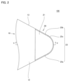
- FIG. 2 is an enlarged view of region II in FIG.
- FIG. 3 is a perspective view of the cutting tool 100.
- FIG. 4 is a perspective view of the main body 10.
- FIG. 5 is a sectional view taken along the line VV in FIG. 2.
- FIG. 6 is a diagram illustrating the relationship between surface unevenness and skewness.
- FIG. 7 is a diagram illustrating another relationship between surface unevenness and skewness.
- the cutting tool of the present disclosure includes a cutting edge portion made of a cubic boron nitride sintered body,
- the cutting edge portion has a flank face, a rake face continuous with the flank face, and a cutting edge located on a ridgeline of the flank face and the rake face,
- the arithmetic mean height Sa of the flank surface is 0.5 ⁇ m or more and 3.0 ⁇ m or less,
- the Sa is measured in accordance with ISO25178-2:2012,
- the oxygen concentration on the flank surface is 10% by mass or more and 50% by mass or less.
- the skewness Ssk of the flank surface is -1.0 or more and 1.0 or less,
- the Ssk is preferably measured in accordance with ISO25178-3:2012. This makes it possible to provide a cutting tool with a longer tool life, especially in high-efficiency machining of cast iron.
- the cubic boron nitride sintered body contains cubic boron nitride particles at 30% by volume or more and 95% by volume or less, and a binder,
- the binding material includes an aluminum compound,
- the oxygen concentration in the cubic boron nitride sintered body is preferably less than 10% by mass. This makes it possible to provide a cutting tool with a longer tool life, especially in high-efficiency machining of cast iron.
- the arithmetic mean height Sa of the rake face is preferably 0.5 ⁇ m or less. This makes it possible to provide a cutting tool with a longer tool life, especially in high-efficiency machining of cast iron.
- the notation in the format "A to B” means the upper and lower limits of the range (i.e., from A to B), and when there is no unit described in A and only in B, The units of and the units of B are the same.
- the atomic ratio when a compound or the like is expressed by a chemical formula, unless the atomic ratio is specifically limited, it includes all conventionally known atomic ratios, and should not necessarily be limited to only those in the stoichiometric range.
- AlN when "AlN" is written, the ratio of the number of atoms constituting AlN includes all conventionally known atomic ratios.
- FIGS. 1 to 7 A cutting tool according to an embodiment of the present disclosure will be described using FIGS. 1 to 7.
- One embodiment of the present disclosure (hereinafter also referred to as “this embodiment”) includes a cutting edge portion 20 made of a cubic boron nitride sintered body, The cutting edge portion 20 has a flank surface 22, a rake surface 21 continuous to the flank surface 22, and a cutting edge 23 located on the ridgeline of the flank surface 22 and the rake surface 21,
- the arithmetic mean height Sa of the flank surface 22 is 0.5 ⁇ m or more and 3.0 ⁇ m or less, The Sa is measured in accordance with ISO25178-2:2012,
- the oxygen concentration of the flank 22 is 10% by mass or more and 50% by mass or less.
- the arithmetic mean height Sa of the flank 22 is 0.5 ⁇ m or more.
- aluminum originating from the workpiece (cast iron) is likely to be trapped in the flank surface 22 of the cutting tool 100 during cutting of cast iron.
- a belag of aluminum oxide (Al 2 O 3 ) containing aluminum as a constituent element is likely to be formed on the surface of the flank 22 of the cutting tool. Therefore, in cutting cast iron, the wear resistance of the cutting tool 100 is improved by the bellag.
- the arithmetic mean height Sa of the flank surface 22 is 0.5 ⁇ m or more, bellag is likely to be formed on the surface of the flank surface 22 of the cutting tool 100, so the cutting tool 100% wear resistance is improved.
- the arithmetic mean height Sa of the flank surface 22 is too large, wear will progress locally on the convex portion, and wear resistance will tend to deteriorate.
- the arithmetic mean height Sa of the flank 22 is 3.0 ⁇ m or less. This prevents the cutting resistance on the flank surface 22 of the cutting tool 100 from becoming excessively large, so that the wear resistance of the cutting tool 100 is improved.
- the oxygen concentration of the flank surface 22 is 10% by mass or more and 50% by mass or less.
- the aluminum trapped on the flank surface 22 of the cutting tool 100 is easily oxidized, so that an aluminum oxide (Al 2 O 3 ) belag is more likely to be formed. Therefore, in cutting of cast iron, the wear resistance of the cutting tool 100 is improved due to the bellag generated on the flank surface of the cutting tool 100.
- the wear resistance of the cutting tool 100 can be improved even in high-efficiency machining of cast iron, so it is possible to provide the cutting tool 100 with a long tool life.
- cutting tool 100 (Configuration of cutting tool according to embodiment) The configuration of a cutting tool (hereinafter referred to as "cutting tool 100") according to an embodiment will be described below.
- FIG. 1 is a plan view of the cutting tool 100.
- FIG. 2 is an enlarged view of region II in FIG.
- FIG. 3 is a perspective view of the cutting tool 100.
- the cutting tool 100 includes a main body portion 10 and a cutting edge portion 20.
- “the cutting tool has a main body part and a cutting edge part” refers not only to the case where the cutting tool part (cBN sintered body) is brazed to the main body part (cemented carbide). This concept also includes cases where the entire cutting tool is made of a cubic boron nitride sintered body (solid type).
- FIG. 4 is a perspective view of the main body 10. As shown in FIG. 4, the main body 10 has a bottom surface 11, a top surface 12, and side surfaces 13. The top surface 12 is the opposite surface to the bottom surface 11. The side surface 13 is continuous with the bottom surface 11 and the top surface 12. The bottom surface 11, the top surface 12, and the side surfaces 13 are the bottom surface of the cutting tool 100, the top surface of the cutting tool 100, and the side surfaces of the cutting tool 100, respectively.
- the main body portion 10 has a rhombic shape in plan view (viewed from a direction perpendicular to the top surface 12) (see FIG. 1).
- the "diamond shape" herein includes cases where the corners of the main body 10 in plan view are rounded.
- the shape of the main body portion 10 in plan view is not limited to a diamond shape.
- the shape of the main body portion 10 in plan view may be a quadrangular shape or a triangular shape.
- the "quadrangular shape” and “triangular shape” herein include cases where the corners of the main body 10 in plan view are rounded.
- the top surface 12 includes a seat surface 14 and a support surface 15.
- the seat surface 14 is located at a corner of the main body 10 in plan view.
- the distance between the seat surface 14 and the bottom surface 11 is smaller than the distance between the top surface 12 and the bottom surface 11 other than the seat surface 14. That is, a step is formed between the seat surface 14 and the top surface 12 located outside the seat surface 14.
- the support surface 15 extends along the direction from the bottom surface 11 toward the top surface 12, and is continuous with the seat surface 14 and the top surface 12 other than the seat surface 14.
- the cutting edge portion 20 includes a flank surface 22, a rake surface 21 continuous to the flank surface 22, and a cutting edge 23 located on the ridgeline of the flank surface 22 and the rake surface 21.
- the cutting edge portion 20 further includes a bottom surface 24 and a supported surface 25 (see FIG. 5).
- the flank surface 22 is continuous with the side surface 13 on the side opposite to the rake surface 21.
- the flank surface 22 is continuous with the rake surface 21 and the bottom surface 24.
- the flank 22 has a first flank 22a, a second flank 22b, and a third flank 22c.
- the first flank surface 22a and the second flank surface 22b are configured by a plane.
- the third flank surface 22c is formed of a curved surface.
- the third flank surface 22c is located between the first flank surface 22a and the second flank surface 22b, and is continuous with both the first flank surface 22a and the second flank surface 22b.
- the cutting edge 23 is formed on the ridgeline between the rake face 21 and the flank face 22.
- the cutting edge 23 is, for example, round honed.
- the cutting edge 23 has a first cutting edge 23a, a second cutting edge 23b, and a third cutting edge 23c.
- the first cutting edge 23a is formed on the ridge line between the rake surface 21 and the first flank surface 22a
- the second cutting edge 23b is formed on the ridge line between the rake surface 21 and the second flank surface 22b.
- the third cutting edge 23c is formed on the ridgeline between the rake face 21 and the third flank face 22c.
- the first cutting edge 23a and the second cutting edge 23b extend linearly in plan view.
- the third cutting edge 23c is connected to the first cutting edge 23a at one end, and connected to the second cutting edge 23b at the other end.
- the third cutting edge 23c extends in a convex curved shape toward the outside of the cutting tool 100 in plan view. That is, an imaginary straight line connecting one end of the third cutting edge 23c and the other end of the third cutting edge 23c passes on the rake face 21.
- the cutting edge portion has a coating on the surface of the flank surface 22 from the viewpoint of keeping the arithmetic mean height Sa of the flank surface, the skewness Ssk of the flank surface, and the oxygen concentration of the flank surface within desired ranges. It is preferable not to have it.
- the arithmetic mean height Sa of the flank 22 is 0.5 ⁇ m or more and 3.0 ⁇ m or less. Note that here, the Sa is measured in accordance with ISO25178-2:2012.
- the "arithmetic mean height Sa" here is a parameter obtained by extending the arithmetic mean roughness Ra (arithmetic mean height of a line) to a surface, and the height of each point relative to the average surface of the surface. Represents the average of the absolute values of the differences. Thereby, the wear resistance of the cutting tool 100 can be improved especially in high-efficiency machining of cast iron.
- the lower limit of the arithmetic mean height Sa of the flank 22 is preferably 0.8 ⁇ m or more, more preferably 1.0 ⁇ m or more, and even more preferably 1.2 ⁇ m or more.
- the upper limit of the arithmetic mean height Sa of the flank 22 is preferably 2.8 ⁇ m or less, more preferably 2.6 ⁇ m or less, and even more preferably 2.4 ⁇ m or less.
- the arithmetic mean height Sa of the flank 22 is preferably 0.8 ⁇ m or more and 2.8 ⁇ m or less, more preferably 1.0 ⁇ m or more and 2.6 ⁇ m or less, and 1.2 ⁇ m or more and 2.4 ⁇ m or less. It is even more preferable that there be.
- the skewness Ssk of the flank 22 is preferably -1.0 or more and 1.0 or less. Note that here, the Ssk is measured in accordance with ISO25178-3:2012. Moreover, the "skewness Ssk” here means the skewness of the roughness curve, and is a parameter indicating the degree of skewness between the peaks and valleys of the surface. In other words, “skewness” is an index representing the symmetry between peaks and valleys when the average line L1 is the center, as shown in FIGS. 6 and 7. When the surface is biased downward with respect to the average line L1, the "skewness” takes a positive value (FIG. 6).
- the skewness Ssk of the flank 22 is preferably -0.9 or more and 0.9 or less, more preferably -0.8 or more and 0.8 or less, and -0.7 or more and 0.7 or less. It is even more preferable that there be.
- the arithmetic mean height Sa and the skewness Ssk were determined using a laser microscope ("OPTELICS HYBRID" (trademark) manufactured by Lasertech) with respect to the flank surface 22 of the surface of the cutting tool 100, and were determined according to ISO25178-2:2012 and ISO25178. -3:2012. Specifically, first, on the surface of the cutting tool 100, a portion of the flank surface 22 that is involved in cutting (in other words, an area within 1 mm from the cutting edge ridgeline (i.e., the ridgeline of the flank surface 22 and the rake surface 21) ) as the measurement field of view, five 200 ⁇ m x 200 ⁇ m rectangular fields of view are arbitrarily set.
- the arithmetic mean height and skewness are measured for each of the five measurement fields of view.
- the arithmetic mean height Sa and the skewness Ssk are determined by calculating the mean value of the obtained arithmetic mean heights and the mean value of the obtained skewnesses.
- the arithmetic mean height Sa of the rake face 21, which will be described later, is also determined in the same manner, except that the measurement is performed on the rake face 21 of the surface of the cutting tool 100.
- the arithmetic mean height Sa of the rake face 21 is preferably 0.5 ⁇ m or less. This makes it easier to prevent the occurrence of welding caused by the high affinity between the components of the workpiece and the components of the cubic boron nitride sintered body during cutting. Can improve resistance. If welding of the rake face is prevented, dulling of the sharpness due to changes in the rake angle caused by the welding can be prevented, and therefore resistance to wear of the flank face can be improved. Therefore, the wear resistance of the cutting tool 100 can be further improved.
- the lower limit of the arithmetic mean height Sa of the rake face 21 is preferably 0.05 ⁇ m or more, more preferably 0.08 ⁇ m or more, and even more preferably 0.10 ⁇ m or more.
- the upper limit of the arithmetic mean height Sa of the rake face 21 is preferably 0.28 ⁇ m or less, more preferably 0.26 ⁇ m or less, and even more preferably 0.24 ⁇ m or less.
- the arithmetic mean height Sa of the rake face 21 is preferably 0.05 ⁇ m or more and 0.5 ⁇ m or less, more preferably 0.08 ⁇ m or more and 0.28 ⁇ m or less, and 0.10 ⁇ m or more and 0.26 ⁇ m or less. It is more preferable that Further, it is also preferable that the arithmetic mean height Sa of the rake face 21 is 0.1 ⁇ m or more and 0.5 ⁇ m or less.
- the cutting edge portion 20 is made of a cubic boron nitride (cBN) sintered body.
- cBN cubic boron nitride
- "consisting of a cubic boron nitride sintered body” is not limited to an embodiment consisting only of a cubic boron nitride sintered body, but as long as the effects of the present disclosure are achieved, a cubic boron nitride sintered body is used.
- the concept also includes embodiments containing components other than the cubic boron nitride sintered body (for example, unavoidable impurities).
- unavoidable impurities examples include carbon (C), aluminum (Al), silicon (Si), lithium (Li), calcium (Ca), and magnesium (Mg).
- the content of unavoidable impurities in the cutting edge portion 20 can be, for example, 0% or more and 1% or less on a mass basis.
- the content of unavoidable impurities in the cutting edge portion 20 is measured by ICP (Inductively Coupled Plasma) emission spectrometry (measuring device: Shimadzu Corporation "ICPS-8100" (trademark)).
- the cubic boron nitride sintered body preferably contains cubic boron nitride particles in an amount of 30% by volume or more and 95% by volume or less. As a result, the cubic boron nitride sintered body can have higher hardness, so the cutting tool according to this embodiment can have better wear resistance.
- the cubic boron nitride sintered body preferably contains cubic boron nitride particles in an amount of 40% by volume or more, more preferably 50% by volume or more, and even more preferably 60% by volume or more.
- the cubic boron nitride sintered body preferably contains cubic boron nitride particles at 93% by volume or less, more preferably at most 90% by volume, even more preferably at most 88% by volume.
- the cubic boron nitride sintered body preferably contains cubic boron nitride particles from 40% by volume to 93% by volume, more preferably from 50% by volume to 90% by volume, and from 60% by volume to 88% by volume. It is more preferable to include the following.
- the term "cubic boron nitride particles" as used herein means particles made of cubic boron nitride (cBN).
- the cubic boron nitride particles can contain unavoidable impurities as long as the effects of the present disclosure are achieved.
- the cubic boron nitride sintered body preferably contains a binder.
- the cubic boron nitride sintered body preferably contains 5% by volume or more of the binder, more preferably 7% by volume or more, and even more preferably 10% by volume or more.
- the cubic boron nitride sintered body preferably contains 70% by volume or less of the binder, more preferably 60% by volume or less, and even more preferably 50% by volume or less.
- the cubic boron nitride sintered body preferably contains a binder of 5% by volume or more and 70% by volume or less, more preferably 7% by volume or more and 60% by volume or less, and 10% by volume or more and 50% by volume or less. is even more preferable.
- the cubic boron nitride sintered body may contain inevitable impurities in addition to the cubic boron nitride sintered particles and the binder. Further, the cubic boron nitride sintered body may include the cubic boron nitride sintered particles and the binder, and the cubic boron nitride sintered body may include the cubic boron nitride sintered particles. , the above-mentioned binder, and unavoidable impurities.
- the content of cubic boron nitride particles and the content of the binder were determined using a scanning electron microscope (SEM) ("JSM-7800F” (product name) manufactured by JEOL Ltd.). Microstructure observation, elemental analysis, etc. were performed on the cBN sintered body using an energy dispersive X-ray spectrometer (EDX) (Octane Elect EDS system) (hereinafter also referred to as "SEM-EDX"). This can be confirmed by carrying out the test.
- SEM-EDX energy dispersive X-ray spectrometer
- a cBN sintered body is cut at an arbitrary position to prepare a sample including a cross section of the cBN sintered body.
- a focused ion beam device, a cross-section polisher device, or the like can be used to prepare the cross section.
- the cross section is observed with a SEM at a magnification of 1000 to obtain a backscattered electron image.
- the region where cBN particles exist becomes a black region, and the region where the binder exists becomes a gray region and/or a white region.
- the area ratio of pixels originating from the dark field (pixels originating from cBN particles, pixels originating from the black area in the backscattered electron image) to the total area of the measurement visual field is calculated.
- the calculated area ratio as volume %, the cBN particle content (volume %) can be determined.
- the bonding material includes an aluminum compound.
- the binding material contains an aluminum compound can be specified by XRD (X-ray diffraction measurement). That is, "the binding material contains an aluminum compound” means that the aluminum compound is present in the binding material to the extent that it can be detected by XRD.
- the aluminum compound examples include aluminum nitride (AlN), aluminum oxide (Al 2 O 3 ), aluminum oxynitride (AlON), and aluminum boride (AlB 2 ). From the viewpoint of strengthening the bonding force with cubic boron nitride, the aluminum compound preferably contains aluminum nitride (AlN).
- the content of the aluminum compound in the binder is preferably 5% by volume or more and 70% by volume or less. This facilitates the formation of aluminum oxide (Al 2 O 3 ) belag on the surface of the cutting tool during cutting. Therefore, in the cutting process of cast iron, the wear resistance of the cutting tool 100 is improved by the bellag generated on the surface of the cutting tool 100, so the cutting tool according to the present embodiment has better wear resistance. Can be done.
- the lower limit of the content of the aluminum compound in the binder is preferably 7% by volume or more, more preferably 10% by volume or more, and even more preferably 12% by volume or more.
- the upper limit of the content of the aluminum compound in the binder is preferably 60% by volume or less, more preferably 50% by volume or less, and even more preferably 40% by volume or less.
- the content of the aluminum compound in the binder is preferably 7 volume% or more and 60 volume% or less, more preferably 10 volume% or more and 50 volume% or less, and 12 volume% or more and 40 volume% or less. More preferably.
- the content rate of the aluminum compound in the binder can be specified by the RIR method (Reference Intensity Ratio) using XRD.
- the above-mentioned binding material can contain a component other than the above-mentioned aluminum compound together with the above-mentioned aluminum compound.
- Components other than the aluminum compound include a single element selected from the group consisting of Group 4 elements, Group 5 elements, Group 6 elements, aluminum, silicon, iron, cobalt, and nickel.
- alloys of two or more elements selected from the group consisting of Group 4 elements, Group 5 elements, Group 6 elements, aluminum, silicon, iron, cobalt, and nickel can be mentioned.
- components other than aluminum compounds include intermetallic compounds of two or more elements selected from the group consisting of Group 4 elements, Group 5 elements, Group 6 elements, silicon, iron, cobalt, and nickel.
- components other than the aluminum compound include one element selected from the group consisting of Group 4 elements, Group 5 elements, Group 6 elements, silicon, iron, cobalt, and nickel, nitrogen, carbon, boron, and Examples include compounds comprising at least one element selected from the group consisting of oxygen.
- Components other than aluminum compounds include, for example, titanium nitride (TiN), tungsten carbide (WC), cobalt (Co), titanium boride (TiB 2 ), titanium carbide (TiC), chromium nitride (CrN), and silicon nitride (Si). 3 N 4 ), iron (Fe), and nickel (Ni).
- the types of compounds other than aluminum compounds in the binder in the cubic boron nitride sintered body can be identified by XRD (X-ray diffraction measurement).
- the oxygen concentration on the flank surface is 10% by mass or more and 50% by mass or less.
- the lower limit of the oxygen concentration on the flank is preferably 15% by mass or more, more preferably 20% by mass or more, and even more preferably 25% by mass or more.
- the upper limit of the oxygen concentration on the flank is preferably 45% by mass or less, more preferably 40% by mass or less, and even more preferably 35% by mass or less.
- the oxygen concentration on the flank surface is preferably 15% by mass or more and 45% by mass or less, more preferably 20% by mass or more and 40% by mass or less, and still more preferably 25% by mass or more and 35% by mass or less. preferable.
- the oxygen concentration on the flank surface can be confirmed by performing elemental analysis on the flank surface using SEM-EDX.
- the specific measurement method is as follows.
- the oxygen concentration (mass %) of the flank surface is determined by calculating the average value of the oxygen concentration at five locations in total.
- the oxygen concentration in the cubic boron nitride sintered body is preferably less than 10% by mass.
- bellag is formed on the flank surface of the cutting tool during cutting of cast iron, thereby improving the durability of the cutting tool. Improves abrasion resistance.
- oxygen mainly exists in the binder phase, and if the oxygen concentration in the binder phase is too high, the cubic boron nitride sintered body itself becomes brittle, making it difficult to cut tools. It becomes brittle easily.
- the oxygen concentration in the cubic boron nitride sintered body is more preferably 9.9% by mass or less, even more preferably 9.8% by mass or less, and even more preferably 9.5% by mass or less. Even more preferably, it is less than 8% by weight, even more preferably less than 6% by weight.
- the oxygen concentration in the cubic boron nitride sintered body can be 0.5% by mass or more, 1% by mass or more, or 1.5% by mass or more from the viewpoint of the manufacturing method.
- the oxygen concentration in the cubic boron nitride sintered body can be confirmed by elemental analysis using SEM-EDX.
- the specific measurement method is as follows.
- the oxygen concentration in the cubic boron nitride sintered body can be determined using the same method as in B2 to C2 above.
- the cutting tool of this embodiment includes a first step of preparing a cutting tool precursor having a cutting edge made of a cubic boron nitride sintered body, and a second step of performing surface treatment on the flank of the cutting edge. It can be manufactured by performing and in this order. Each step will be explained below.
- This step is a step of preparing a cutting tool precursor having a cutting edge portion made of a cubic boron nitride sintered body.
- the cubic boron nitride sintered body is obtained by a conventionally known method.
- cBN particles (raw material) and raw material powder constituting the binder phase are placed in a cemented carbide container together with ethanol, and mixed and pulverized using a ball mill mixing method for 20 hours to obtain a mixed powder.
- the above-mentioned mixed powder is filled into a Ta (tantalum) container and vacuum-sealed.
- the vacuum-sealed mixed powder is sintered by holding it under conditions of 3 to 9 GPa and 1100 to 1900° C.
- the cubic boron nitride sintered body obtained thereby is a cutting tool precursor.
- the cutting tool precursor is then formed by bonding the cubic boron nitride sintered body to the main body portion via a bonding material.
- the bonding material include silver solder.
- the molten joining material is solidified by cooling the joined cubic boron nitride sintered body and the main body. Then, by polishing the joint surface between the cubic boron nitride sintered body and the main body, the joint surface between the cubic boron nitride sintered body and the tool base material is smoothed, and a cutting tool precursor is produced.
- This step is a step of performing electrical discharge machining on the cutting tool precursor.
- the cutting tool precursor can be finished into the shape of a cutting tool (that is, it includes a cutting edge portion, and the cutting edge portion includes a flank surface, a rake surface continuous to the flank surface, and a flank surface and the rake surface).
- a cutting tool having a cutting edge located on the ridgeline of the surface is obtained), and the arithmetic mean height Sa of the flank surface at the cutting edge portion of the cutting tool and the skewness Ssk of the flank surface are adjusted to a desired range. be able to.
- the oxygen concentration on the flank surface is 10% by mass or more and 50% by mass or less.
- the electrical discharge machining described above may be performed, for example, in the following manner.
- the cutting tool precursor described above is set in an electrical discharge machine and processed under conditions where the no-load voltage is 50V or more and less than 200V.
- the shape of the wire is preferably bent or needle-like depending on the processing surface.
- the arithmetic mean height Sa of the flank surface at the cutting edge portion is set to 0.5 ⁇ m or more and 3.0 ⁇ m or less, and the oxygen concentration of the flank surface is set to 10 mass% or more and 50 mass% or less.
- the oxygen concentration of the flank surface is set to 10 mass% or more and 50 mass% or less.
- Conventionally, cutting tools that have been subjected to electric discharge machining have been avoided because a brittle layer is formed on the tool surface, which may not be able to withstand high stress during cutting.
- the present inventors have determined that even if a cutting tool is subjected to electrical discharge machining or electrical discharge machining under the above-mentioned no-load voltage conditions, the arithmetic mean height Sa of the flank surface is set to 0.5 ⁇ m or more and 3.0 ⁇ m or less, and It has been newly discovered that when the oxygen concentration on the flank surface is set to 10% by mass or more and 50% by mass or less, high wear resistance can be exhibited even in high-efficiency machining of cast iron.
- ion etching may be further performed on the flank surface.
- the ion etching may be performed under the following conditions, for example. (Ion etching conditions) ⁇ Input gas: Ar or O 2 ⁇ Acceleration voltage: 0.1 kV or more and 10 kV or less ⁇ Oxygen partial pressure: 0.001 Pa or more and 1.000 Pa or less ⁇ Time: 5 minutes or more and 120 minutes or less
- the cutting tool manufacturing method of the present disclosure may further include the step of performing the polishing process on the rake face. This allows the arithmetic mean height Sa of the rake face to be 0.5 ⁇ m or less. Note that the polishing process is performed using a grindstone of #400 or higher.
- the cutting tool precursors according to samples 1 to 16 and 18 to 25 were molded into a predetermined shape (ISO standard: SNGN120408).
- the predetermined shape includes a cutting edge, and the cutting edge has a flank, a rake face continuous to the flank, and a cutting edge located on the ridgeline of the flank and the rake face. .
- the composition of the cubic boron nitride sintered body (the content of cubic boron nitride particles, the content of the binder), the composition of the binder, the oxygen concentration in the cubic boron nitride sintered body, The arithmetic mean height Sa of the flank face, the oxygen concentration of the flank face, the skewness Ssk of the flank face, and the arithmetic mean height Sa of the rake face were measured.
- flank skewness Ssk was determined by the method described in Embodiment 1. The obtained results are shown in the "Ssk” section in the "Flank surface” section of Table 2.
- the cutting tools of Samples 1 to 11 and 18 to 25 correspond to Examples.
- Samples 12 to 16 correspond to comparative examples.
- the cutting tools of samples 1 to 11 and 18 to 25 (example) have excellent wear resistance and long tool life even in high-efficiency machining of cast iron compared to the cutting tools of samples 12 to 16 (comparative examples). It was confirmed that it has.
Landscapes
- Chemical & Material Sciences (AREA)
- Engineering & Computer Science (AREA)
- Ceramic Engineering (AREA)
- Materials Engineering (AREA)
- Organic Chemistry (AREA)
- Structural Engineering (AREA)
- Manufacturing & Machinery (AREA)
- Mechanical Engineering (AREA)
- Health & Medical Sciences (AREA)
- Toxicology (AREA)
- Crystallography & Structural Chemistry (AREA)
- Metallurgy (AREA)
- Inorganic Chemistry (AREA)
- Cutting Tools, Boring Holders, And Turrets (AREA)
Priority Applications (5)
| Application Number | Priority Date | Filing Date | Title |
|---|---|---|---|
| JP2022578847A JP7276980B1 (ja) | 2022-07-21 | 2022-07-21 | 切削工具 |
| PCT/JP2022/028382 WO2024018599A1 (ja) | 2022-07-21 | 2022-07-21 | 切削工具 |
| US18/029,394 US11826834B1 (en) | 2022-07-21 | 2022-07-21 | Cutting tool |
| CN202280057561.8A CN117836079A (zh) | 2022-07-21 | 2022-07-21 | 切削工具 |
| EP22951984.8A EP4559601A4 (en) | 2022-07-21 | 2022-07-21 | CUTTING TOOL |
Applications Claiming Priority (1)
| Application Number | Priority Date | Filing Date | Title |
|---|---|---|---|
| PCT/JP2022/028382 WO2024018599A1 (ja) | 2022-07-21 | 2022-07-21 | 切削工具 |
Publications (1)
| Publication Number | Publication Date |
|---|---|
| WO2024018599A1 true WO2024018599A1 (ja) | 2024-01-25 |
Family
ID=86378133
Family Applications (1)
| Application Number | Title | Priority Date | Filing Date |
|---|---|---|---|
| PCT/JP2022/028382 Ceased WO2024018599A1 (ja) | 2022-07-21 | 2022-07-21 | 切削工具 |
Country Status (5)
| Country | Link |
|---|---|
| US (1) | US11826834B1 (https=) |
| EP (1) | EP4559601A4 (https=) |
| JP (1) | JP7276980B1 (https=) |
| CN (1) | CN117836079A (https=) |
| WO (1) | WO2024018599A1 (https=) |
Families Citing this family (4)
| Publication number | Priority date | Publication date | Assignee | Title |
|---|---|---|---|---|
| US20230219143A1 (en) * | 2020-06-17 | 2023-07-13 | Sumitomo Electric Hardmetal Corp. | Coolant supply mechanism |
| CN121194844A (zh) * | 2023-05-31 | 2025-12-23 | 住友电工硬质合金株式会社 | 切削刀片以及加工方法 |
| JP1771198S (ja) * | 2023-09-08 | 2024-05-23 | 切削工具用インサート | |
| JP1771199S (ja) * | 2023-09-08 | 2024-05-23 | 切削工具用インサート |
Citations (6)
| Publication number | Priority date | Publication date | Assignee | Title |
|---|---|---|---|---|
| JPH01101704U (https=) * | 1987-12-25 | 1989-07-10 | ||
| JPH10217006A (ja) * | 1997-01-29 | 1998-08-18 | Toyota Banmotsupusu Kk | 超砥粒焼結体製刃先チップを有する切削工具及びその製造方法 |
| JP2002126914A (ja) | 2000-10-19 | 2002-05-08 | Sumitomo Electric Ind Ltd | 高精度加工用切削工具 |
| WO2018116524A1 (ja) * | 2016-12-20 | 2018-06-28 | 住友電工ハードメタル株式会社 | 切削工具及びその製造方法 |
| WO2019065397A1 (ja) * | 2017-09-27 | 2019-04-04 | 三菱日立ツール株式会社 | 被覆切削工具 |
| WO2021260778A1 (ja) * | 2020-06-22 | 2021-12-30 | 住友電工ハードメタル株式会社 | 工具及び工具の製造方法 |
Family Cites Families (4)
| Publication number | Priority date | Publication date | Assignee | Title |
|---|---|---|---|---|
| JP4739234B2 (ja) * | 2004-12-03 | 2011-08-03 | 住友電工ハードメタル株式会社 | 刃先交換型切削チップおよびその製造方法 |
| JP2008272863A (ja) * | 2007-04-27 | 2008-11-13 | Allied Material Corp | 気相合成ダイヤモンドチップおよびダイヤモンド工具 |
| US20130022418A1 (en) * | 2010-02-24 | 2013-01-24 | Kyocera Corporation | Cutting tool |
| JP7251716B2 (ja) * | 2020-07-09 | 2023-04-04 | 住友電工ハードメタル株式会社 | ダイヤモンド被覆工具及びその製造方法 |
-
2022
- 2022-07-21 US US18/029,394 patent/US11826834B1/en active Active
- 2022-07-21 EP EP22951984.8A patent/EP4559601A4/en active Pending
- 2022-07-21 JP JP2022578847A patent/JP7276980B1/ja active Active
- 2022-07-21 CN CN202280057561.8A patent/CN117836079A/zh active Pending
- 2022-07-21 WO PCT/JP2022/028382 patent/WO2024018599A1/ja not_active Ceased
Patent Citations (6)
| Publication number | Priority date | Publication date | Assignee | Title |
|---|---|---|---|---|
| JPH01101704U (https=) * | 1987-12-25 | 1989-07-10 | ||
| JPH10217006A (ja) * | 1997-01-29 | 1998-08-18 | Toyota Banmotsupusu Kk | 超砥粒焼結体製刃先チップを有する切削工具及びその製造方法 |
| JP2002126914A (ja) | 2000-10-19 | 2002-05-08 | Sumitomo Electric Ind Ltd | 高精度加工用切削工具 |
| WO2018116524A1 (ja) * | 2016-12-20 | 2018-06-28 | 住友電工ハードメタル株式会社 | 切削工具及びその製造方法 |
| WO2019065397A1 (ja) * | 2017-09-27 | 2019-04-04 | 三菱日立ツール株式会社 | 被覆切削工具 |
| WO2021260778A1 (ja) * | 2020-06-22 | 2021-12-30 | 住友電工ハードメタル株式会社 | 工具及び工具の製造方法 |
Non-Patent Citations (1)
| Title |
|---|
| See also references of EP4559601A4 |
Also Published As
| Publication number | Publication date |
|---|---|
| EP4559601A4 (en) | 2025-08-13 |
| JP7276980B1 (ja) | 2023-05-18 |
| US11826834B1 (en) | 2023-11-28 |
| EP4559601A1 (en) | 2025-05-28 |
| CN117836079A (zh) | 2024-04-05 |
| JPWO2024018599A1 (https=) | 2024-01-25 |
Similar Documents
| Publication | Publication Date | Title |
|---|---|---|
| JP7276980B1 (ja) | 切削工具 | |
| JP5568827B2 (ja) | 立方晶窒化硼素焼結体、及び立方晶窒化硼素焼結体工具 | |
| KR101414910B1 (ko) | 입방정 질화붕소 소결체 공구 | |
| JP7392714B2 (ja) | 超硬合金及びそれを基材として含む切削工具 | |
| KR102738187B1 (ko) | 초경합금, 절삭 공구 및 초경합금의 제조 방법 | |
| WO2014156625A1 (ja) | 立方晶窒化ホウ素焼結体の製造方法および立方晶窒化ホウ素焼結体 | |
| JP7283636B1 (ja) | 超硬合金およびそれを含む工具 | |
| JP7392423B2 (ja) | 超硬合金及びそれを基材として含む切削工具 | |
| CN104942555B (zh) | 立方晶氮化硼基超高压烧结材料制切削工具 | |
| WO2022137399A1 (ja) | 超硬合金およびそれを基材として含む切削工具 | |
| JP2019137914A (ja) | TiN基焼結体およびTiN基焼結体製切削工具 | |
| WO2022137400A1 (ja) | 超硬合金およびそれを基材として含む切削工具 | |
| JP6607470B2 (ja) | 焼結体およびそれを含む切削工具 | |
| JP7691662B2 (ja) | 立方晶窒化硼素焼結体及び被覆立方晶窒化硼素焼結体 | |
| JP6843096B2 (ja) | 立方晶窒化硼素焼結体、及び、立方晶窒化硼素焼結体を有する工具 | |
| US12534412B2 (en) | Cubic boron nitride sintered body and coated cubic boron nitride sintered body | |
| JP7251691B1 (ja) | 超硬合金およびそれを含む工具 | |
| JP7346751B1 (ja) | 立方晶窒化硼素焼結体 | |
| JP7336062B2 (ja) | 立方晶窒化硼素焼結体及び被覆立方晶窒化硼素焼結体 | |
| CN117326873B (zh) | 立方氮化硼烧结体和涂覆立方氮化硼烧结体 | |
| JP7614468B1 (ja) | 立方晶窒化硼素焼結体および工具 | |
| JPWO2021010476A1 (ja) | 立方晶窒化硼素焼結体 | |
| JP7452762B1 (ja) | 超硬合金およびそれを含む工具 | |
| JP2005206912A (ja) | 被覆超硬合金部材 | |
| WO2019159781A1 (ja) | TiN基焼結体およびTiN基焼結体製切削工具 |
Legal Events
| Date | Code | Title | Description |
|---|---|---|---|
| WWE | Wipo information: entry into national phase |
Ref document number: 2022578847 Country of ref document: JP |
|
| WWE | Wipo information: entry into national phase |
Ref document number: 202280057561.8 Country of ref document: CN |
|
| WWE | Wipo information: entry into national phase |
Ref document number: 202447013922 Country of ref document: IN |
|
| 121 | Ep: the epo has been informed by wipo that ep was designated in this application |
Ref document number: 22951984 Country of ref document: EP Kind code of ref document: A1 |
|
| WWE | Wipo information: entry into national phase |
Ref document number: 2022951984 Country of ref document: EP |
|
| NENP | Non-entry into the national phase |
Ref country code: DE |
|
| ENP | Entry into the national phase |
Ref document number: 2022951984 Country of ref document: EP Effective date: 20250221 |
|
| WWP | Wipo information: published in national office |
Ref document number: 2022951984 Country of ref document: EP |