WO2024018503A1 - ロータ用スリーブおよびロータ - Google Patents
ロータ用スリーブおよびロータ Download PDFInfo
- Publication number
- WO2024018503A1 WO2024018503A1 PCT/JP2022/027988 JP2022027988W WO2024018503A1 WO 2024018503 A1 WO2024018503 A1 WO 2024018503A1 JP 2022027988 W JP2022027988 W JP 2022027988W WO 2024018503 A1 WO2024018503 A1 WO 2024018503A1
- Authority
- WO
- WIPO (PCT)
- Prior art keywords
- diameter hole
- hole
- small
- groove
- diameter
- Prior art date
- Legal status (The legal status is an assumption and is not a legal conclusion. Google has not performed a legal analysis and makes no representation as to the accuracy of the status listed.)
- Ceased
Links
Images




Classifications
-
- H—ELECTRICITY
- H02—GENERATION; CONVERSION OR DISTRIBUTION OF ELECTRIC POWER
- H02K—DYNAMO-ELECTRIC MACHINES
- H02K1/00—Details of the magnetic circuit
- H02K1/06—Details of the magnetic circuit characterised by the shape, form or construction
- H02K1/22—Rotating parts of the magnetic circuit
- H02K1/28—Means for mounting or fastening rotating magnetic parts on to, or to, the rotor structures
- H02K1/30—Means for mounting or fastening rotating magnetic parts on to, or to, the rotor structures using intermediate parts, e.g. spiders
Definitions
- the present disclosure relates to a rotor sleeve and a rotor.
- a rotor that includes a shaft having a stepped portion and a sleeve fitted to the shaft (see, for example, Patent Document 1).
- the sleeve has a hollow portion arranged to cover the stepped portion, and has a hydraulic pressure supply hole communicating with the hollow portion.
- the sleeve When assembling the rotor, the sleeve is fitted around the shaft by shrink fitting. Thereby, the sleeve and the shaft are fixed to each other by high contact pressure on both sides of the hollow portion in the axial direction.
- hydraulic pressure is supplied from the hydraulic supply hole into the hollow part to cause the sleeve to expand in the radial direction due to elastic deformation, and the sleeve is detached from the shaft by the axial force applied to the stepped portion of the shaft.
- the rigidity of the sleeve is low, such as when the sleeve is made thin and lightweight, applying hydraulic pressure inside the hollow part will deform the sleeve into a barrel shape. That is, the amount of deformation at both ends of the sleeve in the axial direction is small, and the contact pressure between the sleeve and the shaft on both sides of the hollow portion in the axial direction cannot be sufficiently reduced. Therefore, even if the sleeve has low rigidity, it is desired to more easily remove the shaft from the sleeve.
- One aspect of the present disclosure includes a through hole into which a shaft is fitted, in which a small diameter shaft portion and a large diameter shaft portion having different outer diameter dimensions are arranged side by side in the axial direction, and the through hole is spaced apart in the axial direction.
- a small-diameter hole and a large-diameter hole which are arranged at positions such that the small-diameter shaft and the large-diameter shaft are closely fitted, respectively; and a small-diameter hole and a large-diameter hole arranged between the small-diameter hole and the large-diameter hole.
- the sleeve for a rotor is provided with a hydraulic pressure supply hole that opens into an intermediate hole portion or an inner surface of the groove.
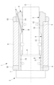
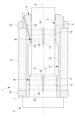
- FIG. 1 is a longitudinal cross-sectional view showing a rotor according to a first embodiment of the present disclosure.
- FIG. 2 is a longitudinal cross-sectional view showing a sleeve according to a first embodiment of the present disclosure, which constitutes the rotor of FIG. 1.
- FIG. FIG. 3 is a longitudinal sectional view illustrating the functions of the rotor of FIG. 1 and the sleeve of FIG. 2;
- FIG. 2 is a front view showing a main shaft constituting the rotor of FIG. 1.
- FIG. FIG. 3 is a longitudinal sectional view showing a first modification of the sleeve of FIG. 2;
- FIG. 3 is a longitudinal cross-sectional view showing a second modification of the sleeve of FIG. 2;
- FIG. 3 is a longitudinal sectional view showing a third modification of the sleeve of FIG. 2;
- FIG. 7 is a longitudinal cross-sectional view showing a rotor according to a second embodiment of the present disclosure.
- 9 is a longitudinal sectional view showing a modification of the rotor of FIG. 8.
- the rotor 1 is, for example, a rotor for a built-in motor whose stator is incorporated into an industrial machine.
- the rotor 1 includes a main shaft (shaft) 2 and a cylindrical sleeve (rotor sleeve) 4 having a through hole 3 into which the main shaft 2 is fitted.
- the main shaft 2 includes a small diameter shaft portion 5 and a large diameter shaft portion 6 that are arranged side by side in the direction of the axis O.
- the main shaft 2 also includes an abutment surface 7 against which the end surface of the sleeve 4 on the large-diameter shaft portion 6 side in the axial direction abuts.
- the small diameter shaft portion 5 and the large diameter shaft portion 6 each have a smooth cylindrical surface, and the large diameter shaft portion 6 has a larger outer diameter dimension than the small diameter shaft portion 5.
- a step 8 having a height corresponding to the difference in outer diameter dimension (radius) is formed between the small diameter shaft portion 5 and the large diameter shaft portion 6.
- An iron core 9 is fitted onto the outer surface of the sleeve 4 by shrink fitting.
- Side rings 10 are fixed to both ends of the iron core 9 in the direction of the axis O.
- the side ring 10 has a larger outer diameter than the iron core 9 and protects the iron core 9 from coming into contact with the inner surface of the stator when the rotor 1 is inserted into the stator. Further, the side ring 10 is provided with a plurality of screw holes (not shown) for fixing a mass for adjusting the balance of the rotor 1.
- the side ring 10 is made of a non-magnetic material and blocks the magnetic path from the iron core 9. Since the linear expansion coefficient of the non-magnetic material is generally larger than that of the magnetic material constituting the iron core 9, the non-magnetic material is fixed to the outer surface of the sleeve 4 by shrink fitting with a larger interference than the iron core 9.
- the through hole 3 of the sleeve 4 has a large diameter hole 11 at one end in the direction of the axis O, into which the large diameter shaft 6 of the main shaft 2 is tightly fitted. Further, the through hole 3 of the sleeve 4 has a small diameter hole portion 12 at the other end in the direction of the axis O, into which the small diameter shaft portion 5 of the main shaft 2 is tightly fitted. In this embodiment, the length dimensions of the small diameter hole portion 12 and the large diameter hole portion 11 in the direction of the axis O are approximately the same.
- the through hole 3 of the sleeve 4 includes an intermediate hole portion 13 at a position sandwiched between the small diameter hole portion 12 and the large diameter hole portion 11 in the direction of the axis O.
- the intermediate hole 13 has a longer length in the direction of the axis O than the small diameter hole 12 and the large diameter hole 11, and a larger inner diameter than the large diameter hole 11.
- a hydraulic pressure supply hole 14 for supplying hydraulic pressure from the outside is opened on the inner surface of the intermediate hole portion 13 .
- a spiral groove (groove) 15 is formed on the inner surface of the small diameter hole 12 and the large diameter hole 11 of the sleeve 4.
- the spiral groove 15 is formed from an intermediate position in the axis O direction of the small diameter hole 12 and the large diameter hole 11 to a boundary position with the intermediate hole 13 and is connected to the intermediate hole 13 .
- the spiral groove 15 has a predetermined groove width and a predetermined pitch, and rotates a plurality of times along the axis O direction.
- the circumferential direction of the spiral groove 15 may be arbitrary.
- the width, pitch, and number of turns of the spiral groove 15 are appropriately set based on the magnitude of the radial force obtained by the supplied hydraulic pressure.
- the radial force obtained by the hydraulic pressure can be increased.
- the contact areas between the small-diameter hole 12 and the small-diameter shaft 5 and between the large-diameter hole 11 and the large-diameter shaft 6 become smaller, and the frictional force between them becomes smaller.
- the width, pitch, and number of turns of the spiral groove 15 are set to appropriate values based on the relationship between the magnitude of the radial force obtained by the hydraulic pressure and the frictional force.
- the iron core and the side ring 10 are previously fitted to the outer surface of the sleeve 4 by shrink fitting.
- the main shaft 2 is inserted into the through hole 3 of the sleeve 4 into the assembly of the sleeve 4, the iron core 9, and the side ring 10 from the left side to the right side in FIG. 1 by shrink fitting.
- the main shaft 2 and the sleeve 4 can be positioned in the direction of the axis O.
- a cylindrical first space A is defined between the intermediate hole portion 13 and the outer surface of the main shaft 2 facing in the radial direction.
- a spiral second space B having a dead end at one end is formed between the spiral groove 15 and the outer surface of the main shaft 2 facing the spiral groove 15, respectively. defined.
- Each spiral second space B opens into the first space A at the other end.
- high-pressure oil pressure is supplied into the first space A via the oil pressure supply hole 14.
- the hydraulic pressure supplied to the first space A is also supplied to a spiral second space B connected to the first space A.
- hydraulic pressure acts to expand the sleeve 4 in the radial direction, as shown by the arrows in FIG. Furthermore, as shown by the arrow, an axial force proportional to the difference in cross-sectional area between the large-diameter shaft portion 6 and the small-diameter shaft portion 5 acts on the step 8 provided on the main shaft 2 .
- the sleeves can also be formed in the small diameter hole section 12 and the large diameter hole section 11, as shown by the arrows. 4 is expanded in the radial direction.
- the contact pressure between the small diameter shaft part 5 and the small diameter hole part 12 and the contact pressure between the large diameter shaft part 6 and the large diameter hole part 11 are reduced, and the axial force generated by the hydraulic pressure causes the sleeve 4 to The main shaft 2 can be easily extracted from the main shaft 2.
- the intermediate hole portion 13 is longer in the axis O direction than the small diameter hole portion 12 and the large diameter hole portion 11, even with low hydraulic pressure, the sleeve 4 can be inserted in the center portion of the sleeve 4 in the axis O direction. It is possible to generate a large force that increases the
- the side rings 10 are fitted to both ends of the sleeve 4 in the direction of the axis O with a large interference, the expansion of the hydraulic pressure in the radial direction is suppressed more than in the center part in the direction of the axis O. Therefore, especially when the sleeve 4 is made thin and lightweight, the sleeve 4 tends to be elastically deformed into a so-called barrel shape, which is large at the center in the direction of the axis O and small at both ends, by the supply of hydraulic pressure.
- the spiral grooves 15 on the inner surfaces of the small diameter hole section 12 and the large diameter hole section 11 it is possible to generate a force that expands the sleeve 4 in the radial direction even at both ends in the direction of the axis O. .
- the contact pressure between the small diameter hole part 12 and the small diameter shaft part 5 and between the large diameter hole part 11 and the large diameter shaft part 6 can be easily reduced. That is, even if the sleeve 4 is made thinner and lighter, there is an advantage that the elastic deformation of the barrel shape caused by the supply of hydraulic pressure can be alleviated, and the main shaft 2 can be easily extracted from the sleeve 4.
- the sleeve 4 and rotor 1 can be made thinner and lighter, and the rotor 1 and the motor can be made lighter and less expensive, and the main shaft 2 can have a larger diameter and higher rigidity. be able to.
- the spiral groove 15 is formed on the inner surface of the small diameter hole section 12 and the large diameter hole section 11, there is no need to process grooves on the outer surface of the main shaft 2. .
- the main spindle 2 is prepared by the user, there is an advantage that there is no need to process grooves on the outer surface of the main spindle 2, thereby eliminating the burden of special processing on the user.
- the inner diameter of the intermediate hole 13 is set larger than that of the large diameter hole 11. Accordingly, it is sufficient to prepare the main shaft 2 with a simple shape having two cylindrical surfaces, a smooth small-diameter shaft portion 5 and a smooth large-diameter shaft portion 6 with different diameter dimensions. This also eliminates the need for the user to perform any special processing on the spindle 2.
- the small diameter shaft section 5 can be inserted into the intermediate hole section 13. It can be fitted into the small diameter hole 12 without contacting the inner surface. Therefore, the work of inserting the main shaft 2 into the sleeve 4 is easy.
- the intermediate hole portion 13 is formed longer in the axis O direction than the small diameter hole portion 12 and the large diameter hole portion 11.
- a gap is formed in the radial direction between the outer surface of the main shaft 2 and the main shaft 2 and the sleeve 4 do not fit into each other, so that requirements for surface roughness and surface accuracy are low.
- Precise machining is required only for the small-diameter hole 12 and large-diameter hole 11 located at both ends of the sleeve 4 in the direction of the axis O, and for the small-diameter shaft 5 and large-diameter shaft 6 that fit into these. be. Therefore, in the sleeve 4, the area to be precisely machined can be limited to a part of the sleeve 4 in the direction of the axis O, rather than the entire length of the sleeve 4, and there is an advantage that the machining cost can be reduced.
- main shaft 2 there is no need to perform precision machining on the entire range of the small diameter shaft portion 5 and the large diameter shaft portion 6, and as shown by hatching in FIG. Only the mating area needs to be precisely machined. This also reduces the burden on the user.
- the spiral grooves 15 formed in the small diameter hole portion 12 and the large diameter hole portion 11 are made to rotate around the axis O multiple times at a predetermined pitch.
- the spiral groove 15 is a groove distributed in the circumferential direction in the small diameter hole portion 12 and the large diameter hole portion 11.
- the radial force generated by the hydraulic pressure can be distributed almost uniformly in the axis O direction and the circumferential direction of the small diameter hole portion 12 and the large diameter hole portion 11. Therefore, the small-diameter hole portion 12 and the large-diameter hole portion 11 can be uniformly expanded in the circumferential direction, and the contact pressure can be evenly reduced.
- the spiral groove 15 is provided in the small diameter hole 12 and the large diameter hole 11.
- a plurality of circumferential grooves 16 which extend in an annular shape in the circumferential direction are provided at intervals in the direction of the axis O, and extend along the direction of the axis O at any position in the circumferential direction.
- a straight connecting groove 17 may also be provided.
- the connection groove 17 connects the plurality of circumferential grooves 16 to the intermediate hole portion 13.
- the circumferential grooves 16 are distributed in the axis O direction and the circumferential direction, and the hydraulic pressure supplied to the first space A can be supplied into each circumferential groove 16 via the connecting groove 17.
- the annular circumferential groove 16 and the linear connecting groove 17 can be machined more easily than the spiral groove 15.
- a plurality of linear grooves (grooves) 18 extending linearly along the axis O direction may be arranged at intervals in the circumferential direction.
- Each straight groove 18 extends from a midway position in the axis O direction of the small diameter hole 12 and the large diameter hole 11 to the boundary with the intermediate hole 13 and is connected to the intermediate hole 13 .
- linear grooves 18 This also allows the linear grooves 18 to be distributed in the circumferential direction, and the hydraulic pressure supplied to the first space A to be supplied to each linear groove 18. Moreover, the straight groove 18 can be processed more easily than the spiral groove 15. Further, the plurality of straight grooves 18 formed at intervals in the circumferential direction may be twisted around the axis O, as shown in FIG.
- the inner diameter of the intermediate hole portion 13 is formed larger than that of the large diameter hole portion 11, but it may be the same as the large diameter hole portion 11, or may be larger than the small diameter hole portion 12, and the inner diameter of the intermediate hole portion 13 is larger than that of the large diameter hole portion 11. The following may be sufficient. If it is larger than the small diameter hole 12, it is possible to generate axial force due to hydraulic pressure, and it is easy to insert the main shaft 2 into the sleeve 4.
- the dimension of the intermediate hole 13 in the axis O direction is set larger than the dimensions of the small diameter hole 12 and the large diameter hole 11 in the axis O direction.
- the dimension of the intermediate hole 13 in the direction of the axis O may be less than or equal to the dimension of the small diameter hole 12 and the large diameter hole 11 in the direction of the axis O.
- the rotor 20 according to this embodiment has the first feature that the spiral groove 15 is not provided in the sleeve 4 but is formed in the small diameter shaft portion 5 and the large diameter shaft portion 6 of the main shaft 2. This is different from the rotor 1 according to the embodiment.
- the spiral groove 15 extends from an intermediate position in the axis O direction of the small diameter shaft portion 5 facing the small diameter hole portion 12 to a position beyond the boundary between the small diameter hole portion 12 and the intermediate hole portion 13. Further, the spiral groove 15 extends from an intermediate position in the direction of the axis O of the large diameter shaft portion 6 facing the large diameter hole portion 11 to the boundary between the large diameter hole portion 11 and the intermediate hole portion 13 .
- hydraulic pressure is also supplied from the first space A to the spiral second space B. Further, it is possible to generate a force that expands the sleeve 4 in the radial direction not only in the intermediate hole portion 13 but also in the small diameter hole portion 12 and the large diameter hole portion 11.
- a plurality of annular circumferential grooves 16 may be provided on the inner surface of the small diameter hole section 12 and the large diameter hole section 11, and a linear connecting groove 17 may be provided on the outer surface of the main shaft 2.
- a plurality of annular circumferential grooves 16 are formed on the outer surfaces of the small-diameter shaft portion 5 and large-diameter shaft portion 6, and linear connecting grooves 17 are formed on the inner surfaces of the small-diameter hole portion 12 and the large-diameter hole portion 11, respectively. may also be provided.
- At least one of the spiral groove 15, the circumferential groove 16, the connecting groove 17, and the straight groove 18 may be provided in the small diameter hole 12, the small diameter shaft 5, the large diameter hole 11, and the large diameter shaft 6.
- the hydraulic pressure supply hole 14 is opened in the intermediate hole portion 13, but instead of this, a spiral groove 15, a circumferential groove 16, a circumferential groove 16, Either the connecting groove 17 or the straight groove 18 may be opened.
Landscapes
- Engineering & Computer Science (AREA)
- Power Engineering (AREA)
- Shafts, Cranks, Connecting Bars, And Related Bearings (AREA)
- Iron Core Of Rotating Electric Machines (AREA)
- Details And Applications Of Rotary Liquid Pumps (AREA)
- Sliding-Contact Bearings (AREA)
- Applications Or Details Of Rotary Compressors (AREA)
Priority Applications (6)
| Application Number | Priority Date | Filing Date | Title |
|---|---|---|---|
| JP2022569084A JP7219375B1 (ja) | 2022-07-19 | 2022-07-19 | ロータ用スリーブおよびロータ |
| CN202280098002.1A CN119547300A (zh) | 2022-07-19 | 2022-07-19 | 转子用套筒以及转子 |
| US18/877,383 US20250385558A1 (en) | 2022-07-19 | 2022-07-19 | Rotor sleeve and rotor |
| DE112022007152.4T DE112022007152T5 (de) | 2022-07-19 | 2022-07-19 | Rotorhülse und Rotor |
| PCT/JP2022/027988 WO2024018503A1 (ja) | 2022-07-19 | 2022-07-19 | ロータ用スリーブおよびロータ |
| TW112125739A TW202406268A (zh) | 2022-07-19 | 2023-07-10 | 轉子套筒及轉子 |
Applications Claiming Priority (1)
| Application Number | Priority Date | Filing Date | Title |
|---|---|---|---|
| PCT/JP2022/027988 WO2024018503A1 (ja) | 2022-07-19 | 2022-07-19 | ロータ用スリーブおよびロータ |
Publications (1)
| Publication Number | Publication Date |
|---|---|
| WO2024018503A1 true WO2024018503A1 (ja) | 2024-01-25 |
Family
ID=85158973
Family Applications (1)
| Application Number | Title | Priority Date | Filing Date |
|---|---|---|---|
| PCT/JP2022/027988 Ceased WO2024018503A1 (ja) | 2022-07-19 | 2022-07-19 | ロータ用スリーブおよびロータ |
Country Status (6)
| Country | Link |
|---|---|
| US (1) | US20250385558A1 (https=) |
| JP (1) | JP7219375B1 (https=) |
| CN (1) | CN119547300A (https=) |
| DE (1) | DE112022007152T5 (https=) |
| TW (1) | TW202406268A (https=) |
| WO (1) | WO2024018503A1 (https=) |
Cited By (1)
| Publication number | Priority date | Publication date | Assignee | Title |
|---|---|---|---|---|
| DE102024206807A1 (de) * | 2024-07-19 | 2026-01-22 | Volkswagen Aktiengesellschaft | Ringmodul und Verfahren zum Aufbau eines Motors einer elektrischen Maschine, Rotor für eine elektrische Maschine und elektrische Maschine |
Families Citing this family (2)
| Publication number | Priority date | Publication date | Assignee | Title |
|---|---|---|---|---|
| DE112023005143T5 (de) * | 2023-03-07 | 2025-10-02 | Fanuc Corporation | Läuferhülse, läufer und motor |
| KR20250066201A (ko) * | 2023-11-06 | 2025-05-13 | 삼성전자주식회사 | 모터 |
Citations (5)
| Publication number | Priority date | Publication date | Assignee | Title |
|---|---|---|---|---|
| JPS62178755U (https=) * | 1986-04-30 | 1987-11-13 | ||
| JPS63105441U (https=) * | 1986-12-26 | 1988-07-08 | ||
| JPS6425854U (https=) * | 1987-08-04 | 1989-02-14 | ||
| JP2008515365A (ja) * | 2004-09-24 | 2008-05-08 | シーメンス アクチエンゲゼルシヤフト | クランプ装置を備えた回転子 |
| JP2013009528A (ja) * | 2011-06-24 | 2013-01-10 | Fanuc Ltd | 回転軸にスリーブを高精度に取り付け可能な電動機 |
-
2022
- 2022-07-19 WO PCT/JP2022/027988 patent/WO2024018503A1/ja not_active Ceased
- 2022-07-19 JP JP2022569084A patent/JP7219375B1/ja active Active
- 2022-07-19 US US18/877,383 patent/US20250385558A1/en active Pending
- 2022-07-19 DE DE112022007152.4T patent/DE112022007152T5/de active Pending
- 2022-07-19 CN CN202280098002.1A patent/CN119547300A/zh active Pending
-
2023
- 2023-07-10 TW TW112125739A patent/TW202406268A/zh unknown
Patent Citations (5)
| Publication number | Priority date | Publication date | Assignee | Title |
|---|---|---|---|---|
| JPS62178755U (https=) * | 1986-04-30 | 1987-11-13 | ||
| JPS63105441U (https=) * | 1986-12-26 | 1988-07-08 | ||
| JPS6425854U (https=) * | 1987-08-04 | 1989-02-14 | ||
| JP2008515365A (ja) * | 2004-09-24 | 2008-05-08 | シーメンス アクチエンゲゼルシヤフト | クランプ装置を備えた回転子 |
| JP2013009528A (ja) * | 2011-06-24 | 2013-01-10 | Fanuc Ltd | 回転軸にスリーブを高精度に取り付け可能な電動機 |
Cited By (1)
| Publication number | Priority date | Publication date | Assignee | Title |
|---|---|---|---|---|
| DE102024206807A1 (de) * | 2024-07-19 | 2026-01-22 | Volkswagen Aktiengesellschaft | Ringmodul und Verfahren zum Aufbau eines Motors einer elektrischen Maschine, Rotor für eine elektrische Maschine und elektrische Maschine |
Also Published As
| Publication number | Publication date |
|---|---|
| JP7219375B1 (ja) | 2023-02-07 |
| JPWO2024018503A1 (https=) | 2024-01-25 |
| DE112022007152T5 (de) | 2025-05-08 |
| CN119547300A (zh) | 2025-02-28 |
| TW202406268A (zh) | 2024-02-01 |
| US20250385558A1 (en) | 2025-12-18 |
Similar Documents
| Publication | Publication Date | Title |
|---|---|---|
| WO2024018503A1 (ja) | ロータ用スリーブおよびロータ | |
| WO2010001776A1 (ja) | 永久磁石式回転機の回転子構造 | |
| JP3646957B2 (ja) | 流体軸受 | |
| JP2016077034A (ja) | バランサ錘を備える回転子、およびモータ | |
| JP2016086611A (ja) | 回転電機のステータコア冷却構造 | |
| WO2021200944A1 (ja) | 固定子、回転子及び回転電機 | |
| KR20030070843A (ko) | 유체 베어링 기구와 이 유체 베어링 기구를 구비한브러시리스 모터 | |
| US7488112B2 (en) | Assembly arrangement between a bearing inner race and a journal, race and journal suitable for such an arrangement, and turbomachine fitted therewith | |
| US20120301216A1 (en) | Shrink disk for the frictional connection of rotating machine parts | |
| US11703086B2 (en) | Apparatus and method for assembling a split sleeve onto a shaft | |
| JPH09303408A (ja) | 軸受構造体 | |
| WO2024185025A1 (ja) | ロータ用スリーブ、ロータおよびモータ | |
| US20080211334A1 (en) | Spindle motor | |
| JPWO2024185025A5 (https=) | ||
| JP5026301B2 (ja) | 転がり軸受ユニットおよびその製造方法 | |
| JP6925519B2 (ja) | 回転電機 | |
| JP7780168B2 (ja) | モータ軸構造 | |
| JPWO2018216160A1 (ja) | 回転子部材及び回転電機 | |
| JPH05106633A (ja) | 動圧軸受 | |
| JPS5834684B2 (ja) | 多円弧形すべり軸受装置 | |
| JP4478942B2 (ja) | 軸受固定装置 | |
| JP4908372B2 (ja) | 静圧流体軸受 | |
| JP7135786B2 (ja) | 固定子、磁気軸受、回転機械 | |
| JP2025063805A (ja) | ボールブッシュおよびその製造方法 | |
| JP2019047679A (ja) | 回転電機とその製造方法 |
Legal Events
| Date | Code | Title | Description |
|---|---|---|---|
| WWE | Wipo information: entry into national phase |
Ref document number: 2022569084 Country of ref document: JP |
|
| 121 | Ep: the epo has been informed by wipo that ep was designated in this application |
Ref document number: 22951894 Country of ref document: EP Kind code of ref document: A1 |
|
| WWE | Wipo information: entry into national phase |
Ref document number: 112022007152 Country of ref document: DE |
|
| WWE | Wipo information: entry into national phase |
Ref document number: 18877383 Country of ref document: US |
|
| WWE | Wipo information: entry into national phase |
Ref document number: 202280098002.1 Country of ref document: CN |
|
| WWP | Wipo information: published in national office |
Ref document number: 202280098002.1 Country of ref document: CN |
|
| WWP | Wipo information: published in national office |
Ref document number: 112022007152 Country of ref document: DE |
|
| 122 | Ep: pct application non-entry in european phase |
Ref document number: 22951894 Country of ref document: EP Kind code of ref document: A1 |
|
| WWP | Wipo information: published in national office |
Ref document number: 18877383 Country of ref document: US |