WO2024018503A1 - Rotor sleeve and rotor - Google Patents
Rotor sleeve and rotor Download PDFInfo
- Publication number
- WO2024018503A1 WO2024018503A1 PCT/JP2022/027988 JP2022027988W WO2024018503A1 WO 2024018503 A1 WO2024018503 A1 WO 2024018503A1 JP 2022027988 W JP2022027988 W JP 2022027988W WO 2024018503 A1 WO2024018503 A1 WO 2024018503A1
- Authority
- WO
- WIPO (PCT)
- Prior art keywords
- diameter hole
- hole
- small
- groove
- diameter
- Prior art date
Links
- XEEYBQQBJWHFJM-UHFFFAOYSA-N Iron Chemical group [Fe] XEEYBQQBJWHFJM-UHFFFAOYSA-N 0.000 description 9
- 239000000696 magnetic material Substances 0.000 description 4
- 230000004048 modification Effects 0.000 description 4
- 238000012986 modification Methods 0.000 description 4
- 230000008901 benefit Effects 0.000 description 3
- 238000003754 machining Methods 0.000 description 3
- 238000000034 method Methods 0.000 description 3
- 230000008569 process Effects 0.000 description 3
- 230000005489 elastic deformation Effects 0.000 description 2
- 238000007792 addition Methods 0.000 description 1
- 230000008859 change Effects 0.000 description 1
- 230000003247 decreasing effect Effects 0.000 description 1
- 238000012217 deletion Methods 0.000 description 1
- 230000037430 deletion Effects 0.000 description 1
- 230000012447 hatching Effects 0.000 description 1
- 230000013011 mating Effects 0.000 description 1
- 238000006467 substitution reaction Methods 0.000 description 1
- 230000003746 surface roughness Effects 0.000 description 1
Images


Classifications
-
- H—ELECTRICITY
- H02—GENERATION; CONVERSION OR DISTRIBUTION OF ELECTRIC POWER
- H02K—DYNAMO-ELECTRIC MACHINES
- H02K1/00—Details of the magnetic circuit
- H02K1/06—Details of the magnetic circuit characterised by the shape, form or construction
- H02K1/22—Rotating parts of the magnetic circuit
- H02K1/28—Means for mounting or fastening rotating magnetic parts on to, or to, the rotor structures
- H02K1/30—Means for mounting or fastening rotating magnetic parts on to, or to, the rotor structures using intermediate parts, e.g. spiders
Definitions
- the present disclosure relates to a rotor sleeve and a rotor.
- a rotor that includes a shaft having a stepped portion and a sleeve fitted to the shaft (see, for example, Patent Document 1).
- the sleeve has a hollow portion arranged to cover the stepped portion, and has a hydraulic pressure supply hole communicating with the hollow portion.
- the sleeve When assembling the rotor, the sleeve is fitted around the shaft by shrink fitting. Thereby, the sleeve and the shaft are fixed to each other by high contact pressure on both sides of the hollow portion in the axial direction.
- hydraulic pressure is supplied from the hydraulic supply hole into the hollow part to cause the sleeve to expand in the radial direction due to elastic deformation, and the sleeve is detached from the shaft by the axial force applied to the stepped portion of the shaft.
- the rigidity of the sleeve is low, such as when the sleeve is made thin and lightweight, applying hydraulic pressure inside the hollow part will deform the sleeve into a barrel shape. That is, the amount of deformation at both ends of the sleeve in the axial direction is small, and the contact pressure between the sleeve and the shaft on both sides of the hollow portion in the axial direction cannot be sufficiently reduced. Therefore, even if the sleeve has low rigidity, it is desired to more easily remove the shaft from the sleeve.
- One aspect of the present disclosure includes a through hole into which a shaft is fitted, in which a small diameter shaft portion and a large diameter shaft portion having different outer diameter dimensions are arranged side by side in the axial direction, and the through hole is spaced apart in the axial direction.
- a small-diameter hole and a large-diameter hole which are arranged at positions such that the small-diameter shaft and the large-diameter shaft are closely fitted, respectively; and a small-diameter hole and a large-diameter hole arranged between the small-diameter hole and the large-diameter hole.
- the sleeve for a rotor is provided with a hydraulic pressure supply hole that opens into an intermediate hole portion or an inner surface of the groove.
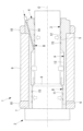
- FIG. 1 is a longitudinal cross-sectional view showing a rotor according to a first embodiment of the present disclosure.
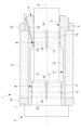
- FIG. 2 is a longitudinal cross-sectional view showing a sleeve according to a first embodiment of the present disclosure, which constitutes the rotor of FIG. 1.
- FIG. FIG. 3 is a longitudinal sectional view illustrating the functions of the rotor of FIG. 1 and the sleeve of FIG. 2;
- FIG. 2 is a front view showing a main shaft constituting the rotor of FIG. 1.
- FIG. FIG. 3 is a longitudinal sectional view showing a first modification of the sleeve of FIG. 2;
- FIG. 3 is a longitudinal cross-sectional view showing a second modification of the sleeve of FIG. 2;
- FIG. 3 is a longitudinal sectional view showing a third modification of the sleeve of FIG. 2;
- FIG. 7 is a longitudinal cross-sectional view showing a rotor according to a second embodiment of the present disclosure.
- 9 is a longitudinal sectional view showing a modification of the rotor of FIG. 8.
- the rotor 1 is, for example, a rotor for a built-in motor whose stator is incorporated into an industrial machine.
- the rotor 1 includes a main shaft (shaft) 2 and a cylindrical sleeve (rotor sleeve) 4 having a through hole 3 into which the main shaft 2 is fitted.
- the main shaft 2 includes a small diameter shaft portion 5 and a large diameter shaft portion 6 that are arranged side by side in the direction of the axis O.
- the main shaft 2 also includes an abutment surface 7 against which the end surface of the sleeve 4 on the large-diameter shaft portion 6 side in the axial direction abuts.
- the small diameter shaft portion 5 and the large diameter shaft portion 6 each have a smooth cylindrical surface, and the large diameter shaft portion 6 has a larger outer diameter dimension than the small diameter shaft portion 5.
- a step 8 having a height corresponding to the difference in outer diameter dimension (radius) is formed between the small diameter shaft portion 5 and the large diameter shaft portion 6.
- An iron core 9 is fitted onto the outer surface of the sleeve 4 by shrink fitting.
- Side rings 10 are fixed to both ends of the iron core 9 in the direction of the axis O.
- the side ring 10 has a larger outer diameter than the iron core 9 and protects the iron core 9 from coming into contact with the inner surface of the stator when the rotor 1 is inserted into the stator. Further, the side ring 10 is provided with a plurality of screw holes (not shown) for fixing a mass for adjusting the balance of the rotor 1.
- the side ring 10 is made of a non-magnetic material and blocks the magnetic path from the iron core 9. Since the linear expansion coefficient of the non-magnetic material is generally larger than that of the magnetic material constituting the iron core 9, the non-magnetic material is fixed to the outer surface of the sleeve 4 by shrink fitting with a larger interference than the iron core 9.
- the through hole 3 of the sleeve 4 has a large diameter hole 11 at one end in the direction of the axis O, into which the large diameter shaft 6 of the main shaft 2 is tightly fitted. Further, the through hole 3 of the sleeve 4 has a small diameter hole portion 12 at the other end in the direction of the axis O, into which the small diameter shaft portion 5 of the main shaft 2 is tightly fitted. In this embodiment, the length dimensions of the small diameter hole portion 12 and the large diameter hole portion 11 in the direction of the axis O are approximately the same.
- the through hole 3 of the sleeve 4 includes an intermediate hole portion 13 at a position sandwiched between the small diameter hole portion 12 and the large diameter hole portion 11 in the direction of the axis O.
- the intermediate hole 13 has a longer length in the direction of the axis O than the small diameter hole 12 and the large diameter hole 11, and a larger inner diameter than the large diameter hole 11.
- a hydraulic pressure supply hole 14 for supplying hydraulic pressure from the outside is opened on the inner surface of the intermediate hole portion 13 .
- a spiral groove (groove) 15 is formed on the inner surface of the small diameter hole 12 and the large diameter hole 11 of the sleeve 4.
- the spiral groove 15 is formed from an intermediate position in the axis O direction of the small diameter hole 12 and the large diameter hole 11 to a boundary position with the intermediate hole 13 and is connected to the intermediate hole 13 .
- the spiral groove 15 has a predetermined groove width and a predetermined pitch, and rotates a plurality of times along the axis O direction.
- the circumferential direction of the spiral groove 15 may be arbitrary.
- the width, pitch, and number of turns of the spiral groove 15 are appropriately set based on the magnitude of the radial force obtained by the supplied hydraulic pressure.
- the radial force obtained by the hydraulic pressure can be increased.
- the contact areas between the small-diameter hole 12 and the small-diameter shaft 5 and between the large-diameter hole 11 and the large-diameter shaft 6 become smaller, and the frictional force between them becomes smaller.
- the width, pitch, and number of turns of the spiral groove 15 are set to appropriate values based on the relationship between the magnitude of the radial force obtained by the hydraulic pressure and the frictional force.
- the iron core and the side ring 10 are previously fitted to the outer surface of the sleeve 4 by shrink fitting.
- the main shaft 2 is inserted into the through hole 3 of the sleeve 4 into the assembly of the sleeve 4, the iron core 9, and the side ring 10 from the left side to the right side in FIG. 1 by shrink fitting.
- the main shaft 2 and the sleeve 4 can be positioned in the direction of the axis O.
- a cylindrical first space A is defined between the intermediate hole portion 13 and the outer surface of the main shaft 2 facing in the radial direction.
- a spiral second space B having a dead end at one end is formed between the spiral groove 15 and the outer surface of the main shaft 2 facing the spiral groove 15, respectively. defined.
- Each spiral second space B opens into the first space A at the other end.
- high-pressure oil pressure is supplied into the first space A via the oil pressure supply hole 14.
- the hydraulic pressure supplied to the first space A is also supplied to a spiral second space B connected to the first space A.
- hydraulic pressure acts to expand the sleeve 4 in the radial direction, as shown by the arrows in FIG. Furthermore, as shown by the arrow, an axial force proportional to the difference in cross-sectional area between the large-diameter shaft portion 6 and the small-diameter shaft portion 5 acts on the step 8 provided on the main shaft 2 .
- the sleeves can also be formed in the small diameter hole section 12 and the large diameter hole section 11, as shown by the arrows. 4 is expanded in the radial direction.
- the contact pressure between the small diameter shaft part 5 and the small diameter hole part 12 and the contact pressure between the large diameter shaft part 6 and the large diameter hole part 11 are reduced, and the axial force generated by the hydraulic pressure causes the sleeve 4 to The main shaft 2 can be easily extracted from the main shaft 2.
- the intermediate hole portion 13 is longer in the axis O direction than the small diameter hole portion 12 and the large diameter hole portion 11, even with low hydraulic pressure, the sleeve 4 can be inserted in the center portion of the sleeve 4 in the axis O direction. It is possible to generate a large force that increases the
- the side rings 10 are fitted to both ends of the sleeve 4 in the direction of the axis O with a large interference, the expansion of the hydraulic pressure in the radial direction is suppressed more than in the center part in the direction of the axis O. Therefore, especially when the sleeve 4 is made thin and lightweight, the sleeve 4 tends to be elastically deformed into a so-called barrel shape, which is large at the center in the direction of the axis O and small at both ends, by the supply of hydraulic pressure.
- the spiral grooves 15 on the inner surfaces of the small diameter hole section 12 and the large diameter hole section 11 it is possible to generate a force that expands the sleeve 4 in the radial direction even at both ends in the direction of the axis O. .
- the contact pressure between the small diameter hole part 12 and the small diameter shaft part 5 and between the large diameter hole part 11 and the large diameter shaft part 6 can be easily reduced. That is, even if the sleeve 4 is made thinner and lighter, there is an advantage that the elastic deformation of the barrel shape caused by the supply of hydraulic pressure can be alleviated, and the main shaft 2 can be easily extracted from the sleeve 4.
- the sleeve 4 and rotor 1 can be made thinner and lighter, and the rotor 1 and the motor can be made lighter and less expensive, and the main shaft 2 can have a larger diameter and higher rigidity. be able to.
- the spiral groove 15 is formed on the inner surface of the small diameter hole section 12 and the large diameter hole section 11, there is no need to process grooves on the outer surface of the main shaft 2. .
- the main spindle 2 is prepared by the user, there is an advantage that there is no need to process grooves on the outer surface of the main spindle 2, thereby eliminating the burden of special processing on the user.
- the inner diameter of the intermediate hole 13 is set larger than that of the large diameter hole 11. Accordingly, it is sufficient to prepare the main shaft 2 with a simple shape having two cylindrical surfaces, a smooth small-diameter shaft portion 5 and a smooth large-diameter shaft portion 6 with different diameter dimensions. This also eliminates the need for the user to perform any special processing on the spindle 2.
- the small diameter shaft section 5 can be inserted into the intermediate hole section 13. It can be fitted into the small diameter hole 12 without contacting the inner surface. Therefore, the work of inserting the main shaft 2 into the sleeve 4 is easy.
- the intermediate hole portion 13 is formed longer in the axis O direction than the small diameter hole portion 12 and the large diameter hole portion 11.
- a gap is formed in the radial direction between the outer surface of the main shaft 2 and the main shaft 2 and the sleeve 4 do not fit into each other, so that requirements for surface roughness and surface accuracy are low.
- Precise machining is required only for the small-diameter hole 12 and large-diameter hole 11 located at both ends of the sleeve 4 in the direction of the axis O, and for the small-diameter shaft 5 and large-diameter shaft 6 that fit into these. be. Therefore, in the sleeve 4, the area to be precisely machined can be limited to a part of the sleeve 4 in the direction of the axis O, rather than the entire length of the sleeve 4, and there is an advantage that the machining cost can be reduced.
- main shaft 2 there is no need to perform precision machining on the entire range of the small diameter shaft portion 5 and the large diameter shaft portion 6, and as shown by hatching in FIG. Only the mating area needs to be precisely machined. This also reduces the burden on the user.
- the spiral grooves 15 formed in the small diameter hole portion 12 and the large diameter hole portion 11 are made to rotate around the axis O multiple times at a predetermined pitch.
- the spiral groove 15 is a groove distributed in the circumferential direction in the small diameter hole portion 12 and the large diameter hole portion 11.
- the radial force generated by the hydraulic pressure can be distributed almost uniformly in the axis O direction and the circumferential direction of the small diameter hole portion 12 and the large diameter hole portion 11. Therefore, the small-diameter hole portion 12 and the large-diameter hole portion 11 can be uniformly expanded in the circumferential direction, and the contact pressure can be evenly reduced.
- the spiral groove 15 is provided in the small diameter hole 12 and the large diameter hole 11.
- a plurality of circumferential grooves 16 which extend in an annular shape in the circumferential direction are provided at intervals in the direction of the axis O, and extend along the direction of the axis O at any position in the circumferential direction.
- a straight connecting groove 17 may also be provided.
- the connection groove 17 connects the plurality of circumferential grooves 16 to the intermediate hole portion 13.
- the circumferential grooves 16 are distributed in the axis O direction and the circumferential direction, and the hydraulic pressure supplied to the first space A can be supplied into each circumferential groove 16 via the connecting groove 17.
- the annular circumferential groove 16 and the linear connecting groove 17 can be machined more easily than the spiral groove 15.
- a plurality of linear grooves (grooves) 18 extending linearly along the axis O direction may be arranged at intervals in the circumferential direction.
- Each straight groove 18 extends from a midway position in the axis O direction of the small diameter hole 12 and the large diameter hole 11 to the boundary with the intermediate hole 13 and is connected to the intermediate hole 13 .
- linear grooves 18 This also allows the linear grooves 18 to be distributed in the circumferential direction, and the hydraulic pressure supplied to the first space A to be supplied to each linear groove 18. Moreover, the straight groove 18 can be processed more easily than the spiral groove 15. Further, the plurality of straight grooves 18 formed at intervals in the circumferential direction may be twisted around the axis O, as shown in FIG.
- the inner diameter of the intermediate hole portion 13 is formed larger than that of the large diameter hole portion 11, but it may be the same as the large diameter hole portion 11, or may be larger than the small diameter hole portion 12, and the inner diameter of the intermediate hole portion 13 is larger than that of the large diameter hole portion 11. The following may be sufficient. If it is larger than the small diameter hole 12, it is possible to generate axial force due to hydraulic pressure, and it is easy to insert the main shaft 2 into the sleeve 4.
- the dimension of the intermediate hole 13 in the axis O direction is set larger than the dimensions of the small diameter hole 12 and the large diameter hole 11 in the axis O direction.
- the dimension of the intermediate hole 13 in the direction of the axis O may be less than or equal to the dimension of the small diameter hole 12 and the large diameter hole 11 in the direction of the axis O.
- the rotor 20 according to this embodiment has the first feature that the spiral groove 15 is not provided in the sleeve 4 but is formed in the small diameter shaft portion 5 and the large diameter shaft portion 6 of the main shaft 2. This is different from the rotor 1 according to the embodiment.
- the spiral groove 15 extends from an intermediate position in the axis O direction of the small diameter shaft portion 5 facing the small diameter hole portion 12 to a position beyond the boundary between the small diameter hole portion 12 and the intermediate hole portion 13. Further, the spiral groove 15 extends from an intermediate position in the direction of the axis O of the large diameter shaft portion 6 facing the large diameter hole portion 11 to the boundary between the large diameter hole portion 11 and the intermediate hole portion 13 .
- hydraulic pressure is also supplied from the first space A to the spiral second space B. Further, it is possible to generate a force that expands the sleeve 4 in the radial direction not only in the intermediate hole portion 13 but also in the small diameter hole portion 12 and the large diameter hole portion 11.
- a plurality of annular circumferential grooves 16 may be provided on the inner surface of the small diameter hole section 12 and the large diameter hole section 11, and a linear connecting groove 17 may be provided on the outer surface of the main shaft 2.
- a plurality of annular circumferential grooves 16 are formed on the outer surfaces of the small-diameter shaft portion 5 and large-diameter shaft portion 6, and linear connecting grooves 17 are formed on the inner surfaces of the small-diameter hole portion 12 and the large-diameter hole portion 11, respectively. may also be provided.
- At least one of the spiral groove 15, the circumferential groove 16, the connecting groove 17, and the straight groove 18 may be provided in the small diameter hole 12, the small diameter shaft 5, the large diameter hole 11, and the large diameter shaft 6.
- the hydraulic pressure supply hole 14 is opened in the intermediate hole portion 13, but instead of this, a spiral groove 15, a circumferential groove 16, a circumferential groove 16, Either the connecting groove 17 or the straight groove 18 may be opened.
Abstract
This rotor sleeve comprises: a small-diameter hole section and a large-diameter hole section that have through holes for fitting a shaft in which a small-diameter shaft portion and a large-diameter shaft portion that differ in outer diameters are arranged side by side in the axial direction, the through holes being arranged at positions set apart in the axial direction and ensuring tight fitting of the small-diameter shaft portion and large-diameter shaft portion, respectively; and an intermediate hole section disposed between the small-diameter hole section and the large-diameter hole section, the rotor sleeve further comprising: grooves located on the inner surfaces of the small-diameter hole section and large-diameter hole section and extending from intermediate positions in the axial direction of the small-diameter hole section and large-diameter hole section to the intermediate hole section; and a hydraulic pressure supply hole that opens on the inner surface of the intermediate hole section or the groove.
Description
本開示は、ロータ用スリーブおよびロータに関するものである。
The present disclosure relates to a rotor sleeve and a rotor.
段差部を有する軸と、軸に嵌合されるスリーブとを備えるロータが知られている(例えば、特許文献1参照。)。スリーブは、段差部をカバーするように配置される中空部を有し、この中空部と連通する油圧供給孔を有する。
A rotor is known that includes a shaft having a stepped portion and a sleeve fitted to the shaft (see, for example, Patent Document 1). The sleeve has a hollow portion arranged to cover the stepped portion, and has a hydraulic pressure supply hole communicating with the hollow portion.
ロータの組立に当たっては、スリーブを軸に焼き嵌めにより嵌合する。これにより、スリーブと軸とは、中空部を軸線方向に挟んだ両側において、高い接触圧力によって相互に固定される。ロータの分解に当たっては、油圧供給孔から中空部内に油圧を供給し、スリーブを弾性変形により径方向に膨張させるとともに、軸の段差部にかかる軸線方向の力により、スリーブを軸から離脱させる。
When assembling the rotor, the sleeve is fitted around the shaft by shrink fitting. Thereby, the sleeve and the shaft are fixed to each other by high contact pressure on both sides of the hollow portion in the axial direction. To disassemble the rotor, hydraulic pressure is supplied from the hydraulic supply hole into the hollow part to cause the sleeve to expand in the radial direction due to elastic deformation, and the sleeve is detached from the shaft by the axial force applied to the stepped portion of the shaft.
スリーブを薄肉軽量化するなど、スリーブの剛性が低い場合に、中空部内に油圧をかけていくと、スリーブが樽状に変形する。すなわち、スリーブの軸線方向の両端における変形量は小さく、中空部を軸線方向に挟んだ両側におけるスリーブと軸との接触圧力を十分に低下させることができない。したがって、スリーブの剛性が低い場合であっても、より容易にスリーブから軸を離脱させることが望まれている。
If the rigidity of the sleeve is low, such as when the sleeve is made thin and lightweight, applying hydraulic pressure inside the hollow part will deform the sleeve into a barrel shape. That is, the amount of deformation at both ends of the sleeve in the axial direction is small, and the contact pressure between the sleeve and the shaft on both sides of the hollow portion in the axial direction cannot be sufficiently reduced. Therefore, even if the sleeve has low rigidity, it is desired to more easily remove the shaft from the sleeve.
本開示の一態様は、外径寸法の異なる小径軸部と大径軸部とが軸線方向に並んで配置された軸を嵌合させる貫通孔を備え、該貫通孔が、前記軸線方向に離れた位置に配置され前記小径軸部および前記大径軸部をそれぞれ密着状態に嵌合させる小径孔部および大径孔部と、前記小径孔部と前記大径孔部との間に配置された中間孔部とを備え、前記小径孔部および前記大径孔部の内面に、前記小径孔部および前記大径孔部の前記軸線方向の途中位置から前記中間孔部まで延びる溝を備え、前記中間孔部または前記溝の内面に開口する油圧供給孔を備えるロータ用スリーブである。
One aspect of the present disclosure includes a through hole into which a shaft is fitted, in which a small diameter shaft portion and a large diameter shaft portion having different outer diameter dimensions are arranged side by side in the axial direction, and the through hole is spaced apart in the axial direction. a small-diameter hole and a large-diameter hole, which are arranged at positions such that the small-diameter shaft and the large-diameter shaft are closely fitted, respectively; and a small-diameter hole and a large-diameter hole arranged between the small-diameter hole and the large-diameter hole. a groove extending from an intermediate position in the axial direction of the small diameter hole and the large diameter hole to the intermediate hole on the inner surface of the small diameter hole and the large diameter hole; The sleeve for a rotor is provided with a hydraulic pressure supply hole that opens into an intermediate hole portion or an inner surface of the groove.
以下に、本開示の第1の実施形態に係るスリーブ4およびロータ1について図面を参照して説明する。
本実施形態に係るロータ1は、例えば、ステータが産業機械に組み込まれたビルトインモータ用のロータである。ロータ1は、図1に示すように、主軸(軸)2と、主軸2を嵌合させる貫通孔3を備える円筒状のスリーブ(ロータ用スリーブ)4とを備えている。 Below, asleeve 4 and a rotor 1 according to a first embodiment of the present disclosure will be described with reference to the drawings.
Therotor 1 according to this embodiment is, for example, a rotor for a built-in motor whose stator is incorporated into an industrial machine. As shown in FIG. 1, the rotor 1 includes a main shaft (shaft) 2 and a cylindrical sleeve (rotor sleeve) 4 having a through hole 3 into which the main shaft 2 is fitted.
本実施形態に係るロータ1は、例えば、ステータが産業機械に組み込まれたビルトインモータ用のロータである。ロータ1は、図1に示すように、主軸(軸)2と、主軸2を嵌合させる貫通孔3を備える円筒状のスリーブ(ロータ用スリーブ)4とを備えている。 Below, a
The
主軸2は、図1および図4に示すように、軸線O方向に並んで配置される小径軸部5と大径軸部6とを備える。また、主軸2は、スリーブ4の軸線方向の大径軸部6側の端面を突き当てる突当て面7を備える。
As shown in FIGS. 1 and 4, the main shaft 2 includes a small diameter shaft portion 5 and a large diameter shaft portion 6 that are arranged side by side in the direction of the axis O. The main shaft 2 also includes an abutment surface 7 against which the end surface of the sleeve 4 on the large-diameter shaft portion 6 side in the axial direction abuts.
小径軸部5および大径軸部6は、それぞれ平滑な円筒面であり、大径軸部6は、小径軸部5よりも大きな外径寸法を有する。小径軸部5と大径軸部6との間には、外径寸法(半径)の差分に対応する高さの段差8が形成されている。
The small diameter shaft portion 5 and the large diameter shaft portion 6 each have a smooth cylindrical surface, and the large diameter shaft portion 6 has a larger outer diameter dimension than the small diameter shaft portion 5. A step 8 having a height corresponding to the difference in outer diameter dimension (radius) is formed between the small diameter shaft portion 5 and the large diameter shaft portion 6.
スリーブ4の外面には鉄心9が焼き嵌めにより嵌合されている。鉄心9の軸線O方向の両端にはサイドリング10が固定されている。サイドリング10は、鉄心9よりも大きな外径寸法を有し、ロータ1をステータ内に挿入する際にステータ内面に鉄心9が接触しないように保護する。また、サイドリング10は、ロータ1のバランス調整用の質量を固定するための図示しない複数のネジ孔を備えている。
An iron core 9 is fitted onto the outer surface of the sleeve 4 by shrink fitting. Side rings 10 are fixed to both ends of the iron core 9 in the direction of the axis O. The side ring 10 has a larger outer diameter than the iron core 9 and protects the iron core 9 from coming into contact with the inner surface of the stator when the rotor 1 is inserted into the stator. Further, the side ring 10 is provided with a plurality of screw holes (not shown) for fixing a mass for adjusting the balance of the rotor 1.
サイドリング10は非磁性材料により構成され、鉄心9からの磁路を遮断している。非磁性材料の線膨張係数は、一般に鉄心9を構成する磁性材料よりも大きいため、鉄心9よりも大きな締め代によりスリーブ4の外面に焼き嵌めにより固定されている。
The side ring 10 is made of a non-magnetic material and blocks the magnetic path from the iron core 9. Since the linear expansion coefficient of the non-magnetic material is generally larger than that of the magnetic material constituting the iron core 9, the non-magnetic material is fixed to the outer surface of the sleeve 4 by shrink fitting with a larger interference than the iron core 9.
スリーブ4の貫通孔3は、軸線O方向の一端に主軸2の大径軸部6を密着状態に嵌合させる大径孔部11を備えている。また、スリーブ4の貫通孔3は、軸線O方向の他端に、主軸2の小径軸部5を密着状態に嵌合させる小径孔部12を備えている。本実施形態において、小径孔部12と大径孔部11の軸線O方向の長さ寸法はほぼ同等である。
The through hole 3 of the sleeve 4 has a large diameter hole 11 at one end in the direction of the axis O, into which the large diameter shaft 6 of the main shaft 2 is tightly fitted. Further, the through hole 3 of the sleeve 4 has a small diameter hole portion 12 at the other end in the direction of the axis O, into which the small diameter shaft portion 5 of the main shaft 2 is tightly fitted. In this embodiment, the length dimensions of the small diameter hole portion 12 and the large diameter hole portion 11 in the direction of the axis O are approximately the same.
さらに、スリーブ4の貫通孔3は、小径孔部12と大径孔部11との間に軸線O方向に挟まれる位置に、中間孔部13を備えている。本実施形態においては、中間孔部13は、小径孔部12および大径孔部11よりも大きな軸線O方向の長さ寸法と、大径孔部11よりも大きな内径寸法とを有する。また、中間孔部13の内面には、外部から油圧を供給するための油圧供給孔14が開口している。
Further, the through hole 3 of the sleeve 4 includes an intermediate hole portion 13 at a position sandwiched between the small diameter hole portion 12 and the large diameter hole portion 11 in the direction of the axis O. In this embodiment, the intermediate hole 13 has a longer length in the direction of the axis O than the small diameter hole 12 and the large diameter hole 11, and a larger inner diameter than the large diameter hole 11. Furthermore, a hydraulic pressure supply hole 14 for supplying hydraulic pressure from the outside is opened on the inner surface of the intermediate hole portion 13 .
また、本実施形態においては、図2に示すように、スリーブ4の小径孔部12および大径孔部11の内面に、螺旋溝(溝)15が形成されている。螺旋溝15は、小径孔部12および大径孔部11の軸線O方向の途中位置から中間孔部13との境界位置まで形成され、中間孔部13に接続している。
Furthermore, in this embodiment, as shown in FIG. 2, a spiral groove (groove) 15 is formed on the inner surface of the small diameter hole 12 and the large diameter hole 11 of the sleeve 4. The spiral groove 15 is formed from an intermediate position in the axis O direction of the small diameter hole 12 and the large diameter hole 11 to a boundary position with the intermediate hole 13 and is connected to the intermediate hole 13 .
螺旋溝15は、図2に示す例では、所定の溝幅と所定のピッチとを有し、軸線O方向に沿って複数回周回している。螺旋溝15の周回方向は任意でよい。
In the example shown in FIG. 2, the spiral groove 15 has a predetermined groove width and a predetermined pitch, and rotates a plurality of times along the axis O direction. The circumferential direction of the spiral groove 15 may be arbitrary.
螺旋溝15の幅、ピッチおよび周回数は、供給される油圧により得られる径方向の力の大きさから適宜設定されている。螺旋溝15の幅を大きくし、ピッチを小さくし、周回数を多くすると油圧により得られる径方向の力を大きくすることができる。その反面、小径孔部12と小径軸部5、および、大径孔部11と大径軸部6との接触面積が小さくなり、両者間の摩擦力が小さくなる。
The width, pitch, and number of turns of the spiral groove 15 are appropriately set based on the magnitude of the radial force obtained by the supplied hydraulic pressure. By increasing the width of the spiral groove 15, decreasing the pitch, and increasing the number of turns, the radial force obtained by the hydraulic pressure can be increased. On the other hand, the contact areas between the small-diameter hole 12 and the small-diameter shaft 5 and between the large-diameter hole 11 and the large-diameter shaft 6 become smaller, and the frictional force between them becomes smaller.
したがって、螺旋溝15の幅、ピッチおよび周回数は油圧により得られる径方向の力の大きさと摩擦力との関係から適当な大きさに設定される。
Therefore, the width, pitch, and number of turns of the spiral groove 15 are set to appropriate values based on the relationship between the magnitude of the radial force obtained by the hydraulic pressure and the frictional force.
このように構成された本実施形態に係るスリーブ4およびロータ1の作用について、以下に説明する。本実施形態に係るロータ1を組み立てるには、スリーブ4の外面に鉄心およびサイドリング10を、予め焼き嵌めにより嵌合しておく。
The functions of the sleeve 4 and rotor 1 according to the present embodiment configured in this way will be described below. To assemble the rotor 1 according to the present embodiment, the iron core and the side ring 10 are previously fitted to the outer surface of the sleeve 4 by shrink fitting.
そして、スリーブ4と鉄心9とサイドリング10との組立体に対し、スリーブ4の貫通孔3内に、主軸2を、図1において左側から右側に向かって焼き嵌めにより挿入する。主軸2の突当て面7をスリーブ4の大径孔部11側の端面に突き当てることにより、主軸2とスリーブ4とを軸線O方向に位置決めすることができる。
Then, the main shaft 2 is inserted into the through hole 3 of the sleeve 4 into the assembly of the sleeve 4, the iron core 9, and the side ring 10 from the left side to the right side in FIG. 1 by shrink fitting. By abutting the abutting surface 7 of the main shaft 2 against the end surface of the sleeve 4 on the large diameter hole 11 side, the main shaft 2 and the sleeve 4 can be positioned in the direction of the axis O.
この状態において、主軸2の小径軸部5がスリーブ4の小径孔部12に、主軸2の大径軸部6がスリーブ4の大径孔部11に、それぞれ密着状態に嵌合し、主軸2とスリーブ4とが相互に固定される。その結果、主軸2とスリーブ4との間には、密閉された空間が画定される。
In this state, the small diameter shaft portion 5 of the main shaft 2 is tightly fitted into the small diameter hole 12 of the sleeve 4, and the large diameter shaft portion 6 of the main shaft 2 is fitted into the large diameter hole 11 of the sleeve 4 in a tight state. and sleeve 4 are fixed to each other. As a result, a sealed space is defined between the main shaft 2 and the sleeve 4.
中間孔部13の位置においては、中間孔部13に径方向に対向する主軸2の外面との間に円筒状の第1空間Aが画定される。また、小径孔部12および大径孔部11の位置においては、螺旋溝15と螺旋溝15に対向する主軸2の外面との間に、一端が行き止まりとなる螺旋状の第2空間Bがそれぞれ画定される。各螺旋状の第2空間Bは、他端において第1空間Aに開口している。
At the position of the intermediate hole portion 13, a cylindrical first space A is defined between the intermediate hole portion 13 and the outer surface of the main shaft 2 facing in the radial direction. Further, at the positions of the small diameter hole portion 12 and the large diameter hole portion 11, a spiral second space B having a dead end at one end is formed between the spiral groove 15 and the outer surface of the main shaft 2 facing the spiral groove 15, respectively. defined. Each spiral second space B opens into the first space A at the other end.
ロータ1を分解するには、油圧供給孔14を経由して第1空間A内に、高圧の油圧を供給する。第1空間Aに供給された油圧は、第1空間Aに接続する螺旋状の第2空間Bにも供給される。
To disassemble the rotor 1, high-pressure oil pressure is supplied into the first space A via the oil pressure supply hole 14. The hydraulic pressure supplied to the first space A is also supplied to a spiral second space B connected to the first space A.
第1空間Aにおいては、油圧により、図3に矢印によって示されるように、スリーブ4を径方向に拡大させる力が作用する。また、矢印によって示されるように、主軸2に設けられた段差8に、大径軸部6と小径軸部5との断面積の差分に比例する軸力が作用する。
In the first space A, hydraulic pressure acts to expand the sleeve 4 in the radial direction, as shown by the arrows in FIG. Furthermore, as shown by the arrow, an axial force proportional to the difference in cross-sectional area between the large-diameter shaft portion 6 and the small-diameter shaft portion 5 acts on the step 8 provided on the main shaft 2 .
さらに、本実施形態においては、第1空間Aから螺旋状の第2空間Bに油圧が供給されることにより、小径孔部12および大径孔部11においても、矢印によって示されるように、スリーブ4が径方向に拡大させられる。
Furthermore, in the present embodiment, by supplying hydraulic pressure from the first space A to the spiral second space B, the sleeves can also be formed in the small diameter hole section 12 and the large diameter hole section 11, as shown by the arrows. 4 is expanded in the radial direction.
その結果、小径軸部5と小径孔部12との間の接触圧力および大径軸部6と大径孔部11との間の接触圧力が低減し、油圧によって発生した軸力により、スリーブ4から主軸2を容易に抜き出すことができる。
この場合において、中間孔部13は、小径孔部12および大径孔部11よりも軸線O方向に長いので、低圧の油圧でも、スリーブ4の軸線O方向の中央部分に、スリーブ4を径方向に拡大させる大きな力を発生させることができる。 As a result, the contact pressure between the smalldiameter shaft part 5 and the small diameter hole part 12 and the contact pressure between the large diameter shaft part 6 and the large diameter hole part 11 are reduced, and the axial force generated by the hydraulic pressure causes the sleeve 4 to The main shaft 2 can be easily extracted from the main shaft 2.
In this case, since theintermediate hole portion 13 is longer in the axis O direction than the small diameter hole portion 12 and the large diameter hole portion 11, even with low hydraulic pressure, the sleeve 4 can be inserted in the center portion of the sleeve 4 in the axis O direction. It is possible to generate a large force that increases the
この場合において、中間孔部13は、小径孔部12および大径孔部11よりも軸線O方向に長いので、低圧の油圧でも、スリーブ4の軸線O方向の中央部分に、スリーブ4を径方向に拡大させる大きな力を発生させることができる。 As a result, the contact pressure between the small
In this case, since the
一方、スリーブ4の軸線O方向の両端には、サイドリング10が大きな締め代によって嵌合されているので、油圧の径方向の拡大は軸線O方向の中央部分よりも抑制される。したがって、特に、スリーブ4を薄肉軽量化した場合には、スリーブ4は、油圧の供給により、軸線O方向の中央において大きく両端において小さく、いわゆる樽型に弾性変形し易い。
On the other hand, since the side rings 10 are fitted to both ends of the sleeve 4 in the direction of the axis O with a large interference, the expansion of the hydraulic pressure in the radial direction is suppressed more than in the center part in the direction of the axis O. Therefore, especially when the sleeve 4 is made thin and lightweight, the sleeve 4 tends to be elastically deformed into a so-called barrel shape, which is large at the center in the direction of the axis O and small at both ends, by the supply of hydraulic pressure.
本実施形態によれば、小径孔部12および大径孔部11の内面に螺旋溝15を設けることにより、軸線O方向の両端においてもスリーブ4を径方向に拡大させる力を発生させることができる。これにより、小径孔部12と小径軸部5との間および大径孔部11と大径軸部6との間の接触圧力を容易に低減させることができる。
すなわち、スリーブ4を薄肉軽量化しても、油圧の供給による樽型の弾性変形を緩和して、スリーブ4から主軸2を容易に抜き出すことができるという利点がある。 According to this embodiment, by providing thespiral grooves 15 on the inner surfaces of the small diameter hole section 12 and the large diameter hole section 11, it is possible to generate a force that expands the sleeve 4 in the radial direction even at both ends in the direction of the axis O. . Thereby, the contact pressure between the small diameter hole part 12 and the small diameter shaft part 5 and between the large diameter hole part 11 and the large diameter shaft part 6 can be easily reduced.
That is, even if thesleeve 4 is made thinner and lighter, there is an advantage that the elastic deformation of the barrel shape caused by the supply of hydraulic pressure can be alleviated, and the main shaft 2 can be easily extracted from the sleeve 4.
すなわち、スリーブ4を薄肉軽量化しても、油圧の供給による樽型の弾性変形を緩和して、スリーブ4から主軸2を容易に抜き出すことができるという利点がある。 According to this embodiment, by providing the
That is, even if the
その結果、本実施形態に係るスリーブ4およびロータ1によれば、スリーブ4を薄肉軽量化することができ、ロータ1およびモータの軽量化、低コスト化、主軸2の大径高剛性化を図ることができる。
As a result, according to the sleeve 4 and rotor 1 according to the present embodiment, the sleeve 4 can be made thinner and lighter, and the rotor 1 and the motor can be made lighter and less expensive, and the main shaft 2 can have a larger diameter and higher rigidity. be able to.
また、本実施形態に係るスリーブ4およびロータ1によれば、小径孔部12および大径孔部11の内面に螺旋溝15を形成しているので、主軸2の外面に溝加工が不要である。ビルトインモータにおいては、ユーザが主軸2を用意するので、主軸2の外面の溝加工を不要とすることにより、ユーザに特殊な加工の負担をかけずに済むという利点がある。
Furthermore, according to the sleeve 4 and rotor 1 according to the present embodiment, since the spiral groove 15 is formed on the inner surface of the small diameter hole section 12 and the large diameter hole section 11, there is no need to process grooves on the outer surface of the main shaft 2. . In the built-in motor, since the main spindle 2 is prepared by the user, there is an advantage that there is no need to process grooves on the outer surface of the main spindle 2, thereby eliminating the burden of special processing on the user.
また、本実施形態によれば、中間孔部13の内径寸法が大径孔部11よりも大きく設定されている。これにより、主軸2として、径寸法の異なる平滑な小径軸部5と平滑な大径軸部6の2つの円筒面を有する単純な形状のものを用意すれば、足りる。これによっても、ユーザが主軸2に特別な加工を施す必要がない。
Furthermore, according to the present embodiment, the inner diameter of the intermediate hole 13 is set larger than that of the large diameter hole 11. Accordingly, it is sufficient to prepare the main shaft 2 with a simple shape having two cylindrical surfaces, a smooth small-diameter shaft portion 5 and a smooth large-diameter shaft portion 6 with different diameter dimensions. This also eliminates the need for the user to perform any special processing on the spindle 2.
さらに、中間孔部13の内径を小径孔部12の内径よりも大きくすることにより、主軸2をスリーブ4の貫通孔3内に挿入していく作業に当たり、小径軸部5を中間孔部13の内面に接触させることなく小径孔部12に嵌合させることができる。したがって、主軸2のスリーブ4への挿入作業が容易である。
Furthermore, by making the inner diameter of the intermediate hole section 13 larger than the inner diameter of the small diameter hole section 12, when inserting the main shaft 2 into the through hole 3 of the sleeve 4, the small diameter shaft section 5 can be inserted into the intermediate hole section 13. It can be fitted into the small diameter hole 12 without contacting the inner surface. Therefore, the work of inserting the main shaft 2 into the sleeve 4 is easy.
また、本実施形態に係るスリーブ4およびロータ1によれば、中間孔部13が小径孔部12および大径孔部11よりも軸線O方向に長く形成されている。中間孔部13においては主軸2の外面との間に径方向に隙間が形成され、主軸2とスリーブ4とが相互に嵌合しないので、表面粗さおよび面精度に対する要求が低い。
Furthermore, according to the sleeve 4 and rotor 1 according to the present embodiment, the intermediate hole portion 13 is formed longer in the axis O direction than the small diameter hole portion 12 and the large diameter hole portion 11. In the intermediate hole portion 13, a gap is formed in the radial direction between the outer surface of the main shaft 2 and the main shaft 2 and the sleeve 4 do not fit into each other, so that requirements for surface roughness and surface accuracy are low.
精密な加工が必要となるのはスリーブ4の軸線O方向の両端に位置する小径孔部12および大径孔部11、および、これらと嵌合する小径軸部5および大径軸部6のみである。したがって、スリーブ4においては、精密加工される領域をスリーブ4の全長ではなく、スリーブ4の軸線O方向の一部に限定することができ、加工コストを低減することができるという利点がある。
Precise machining is required only for the small-diameter hole 12 and large-diameter hole 11 located at both ends of the sleeve 4 in the direction of the axis O, and for the small-diameter shaft 5 and large-diameter shaft 6 that fit into these. be. Therefore, in the sleeve 4, the area to be precisely machined can be limited to a part of the sleeve 4 in the direction of the axis O, rather than the entire length of the sleeve 4, and there is an advantage that the machining cost can be reduced.
また、主軸2においても、小径軸部5および大径軸部6の全範囲に精密加工を施す必要がなく、図4にハッチングによって示されるように、小径孔部12および大径孔部11と嵌合する領域のみを精密に加工すればよい。これによっても、ユーザにかかる負担を軽減することができる。
Further, in the main shaft 2, there is no need to perform precision machining on the entire range of the small diameter shaft portion 5 and the large diameter shaft portion 6, and as shown by hatching in FIG. Only the mating area needs to be precisely machined. This also reduces the burden on the user.
また、本実施形態においては、小径孔部12および大径孔部11に形成する螺旋溝15を、所定のピッチで軸線O回りに複数回周回させている。螺旋溝15は、小径孔部12および大径孔部11において周方向に分布する溝である。
Furthermore, in this embodiment, the spiral grooves 15 formed in the small diameter hole portion 12 and the large diameter hole portion 11 are made to rotate around the axis O multiple times at a predetermined pitch. The spiral groove 15 is a groove distributed in the circumferential direction in the small diameter hole portion 12 and the large diameter hole portion 11.
これにより、油圧により発生させる径方向の力を小径孔部12および大径孔部11の軸線O方向および周方向にほぼ均一に分布させることができる。したがって、小径孔部12および大径孔部11を周方向に偏りなく拡大させて、満遍なく接触圧力を低減することができる。
Thereby, the radial force generated by the hydraulic pressure can be distributed almost uniformly in the axis O direction and the circumferential direction of the small diameter hole portion 12 and the large diameter hole portion 11. Therefore, the small-diameter hole portion 12 and the large-diameter hole portion 11 can be uniformly expanded in the circumferential direction, and the contact pressure can be evenly reduced.
なお、本実施形態に係るスリーブ4およびロータ1においては、小径孔部12および大径孔部11に螺旋溝15を設けた。これに代えて、図5に示すように、周方向に円環状に延びる周溝16を軸線O方向に間隔をあけて複数設けるとともに、周方向のいずれかの位置に軸線O方向に沿って延びる直線状の接続溝17を設けてもよい。接続溝17は、複数の周溝16を中間孔部13に接続する。
In addition, in the sleeve 4 and rotor 1 according to the present embodiment, the spiral groove 15 is provided in the small diameter hole 12 and the large diameter hole 11. Instead, as shown in FIG. 5, a plurality of circumferential grooves 16 which extend in an annular shape in the circumferential direction are provided at intervals in the direction of the axis O, and extend along the direction of the axis O at any position in the circumferential direction. A straight connecting groove 17 may also be provided. The connection groove 17 connects the plurality of circumferential grooves 16 to the intermediate hole portion 13.
これによっても、周溝16が軸線O方向および周方向に分布し、第1空間Aに供給した油圧を、接続溝17を経由して各周溝16内に供給することができる。円環状の周溝16および直線状の接続溝17の方が、螺旋溝15よりも容易に加工することができる。
With this also, the circumferential grooves 16 are distributed in the axis O direction and the circumferential direction, and the hydraulic pressure supplied to the first space A can be supplied into each circumferential groove 16 via the connecting groove 17. The annular circumferential groove 16 and the linear connecting groove 17 can be machined more easily than the spiral groove 15.
また、図6に示すように、軸線O方向に沿って直線状に延びる直線溝(溝)18を周方向に間隔をあけて複数配置することにしてもよい。各直線溝18は小径孔部12および大径孔部11の軸線O方向の途中位置から、中間孔部13との境界まで延び、中間孔部13に接続している。
Furthermore, as shown in FIG. 6, a plurality of linear grooves (grooves) 18 extending linearly along the axis O direction may be arranged at intervals in the circumferential direction. Each straight groove 18 extends from a midway position in the axis O direction of the small diameter hole 12 and the large diameter hole 11 to the boundary with the intermediate hole 13 and is connected to the intermediate hole 13 .
これによっても直線溝18を周方向に分布させることができ、第1空間Aに供給された油圧を、各直線溝18内に供給することができる。また、直線溝18であれば、螺旋溝15よりも容易に加工することができる。
また、周方向に間隔をあけて複数形成される直線溝18は、図7に示されるように、軸線O回りに捩れていてもよい。 This also allows thelinear grooves 18 to be distributed in the circumferential direction, and the hydraulic pressure supplied to the first space A to be supplied to each linear groove 18. Moreover, the straight groove 18 can be processed more easily than the spiral groove 15.
Further, the plurality ofstraight grooves 18 formed at intervals in the circumferential direction may be twisted around the axis O, as shown in FIG.
また、周方向に間隔をあけて複数形成される直線溝18は、図7に示されるように、軸線O回りに捩れていてもよい。 This also allows the
Further, the plurality of
また、本実施形態においては、中間孔部13の内径を大径孔部11よりも大きく形成したが、大径孔部11と同一でもよく、小径孔部12よりも大きく、大径孔部11以下であってもよい。小径孔部12よりも大きければ、油圧による軸力を発生させることができ、主軸2のスリーブ4への挿入が容易である。
Further, in the present embodiment, the inner diameter of the intermediate hole portion 13 is formed larger than that of the large diameter hole portion 11, but it may be the same as the large diameter hole portion 11, or may be larger than the small diameter hole portion 12, and the inner diameter of the intermediate hole portion 13 is larger than that of the large diameter hole portion 11. The following may be sufficient. If it is larger than the small diameter hole 12, it is possible to generate axial force due to hydraulic pressure, and it is easy to insert the main shaft 2 into the sleeve 4.
また、本実施形態においては、中間孔部13の軸線O方向の寸法を小径孔部12および大径孔部11の軸線O方向の寸法よりも大きく設定した。これに代えて、中間孔部13の軸線O方向の寸法は小径孔部12および大径孔部11の軸線O方向の寸法以下であってもよい
Furthermore, in this embodiment, the dimension of the intermediate hole 13 in the axis O direction is set larger than the dimensions of the small diameter hole 12 and the large diameter hole 11 in the axis O direction. Alternatively, the dimension of the intermediate hole 13 in the direction of the axis O may be less than or equal to the dimension of the small diameter hole 12 and the large diameter hole 11 in the direction of the axis O.
次に、本開示の第2の実施形態に係るロータ20について、図面を参照して以下に説明する。
本実施形態の説明において、上述した第1の実施形態に係るロータ1と構成を共通とする箇所には同一符号を付して説明を省略する。 Next, a rotor 20 according to a second embodiment of the present disclosure will be described below with reference to the drawings.
In the description of this embodiment, parts having the same configuration as therotor 1 according to the first embodiment described above are given the same reference numerals, and the description thereof will be omitted.
本実施形態の説明において、上述した第1の実施形態に係るロータ1と構成を共通とする箇所には同一符号を付して説明を省略する。 Next, a rotor 20 according to a second embodiment of the present disclosure will be described below with reference to the drawings.
In the description of this embodiment, parts having the same configuration as the
本実施形態に係るロータ20は、図8に示すように、螺旋溝15がスリーブ4に設けられず、主軸2の小径軸部5および大径軸部6に形成されている点において、第1の実施形態に係るロータ1と相違している。
As shown in FIG. 8, the rotor 20 according to this embodiment has the first feature that the spiral groove 15 is not provided in the sleeve 4 but is formed in the small diameter shaft portion 5 and the large diameter shaft portion 6 of the main shaft 2. This is different from the rotor 1 according to the embodiment.
螺旋溝15は、小径孔部12に対向する小径軸部5の軸線O方向の途中位置から小径孔部12と中間孔部13との境界を超える位置まで延びている。また、螺旋溝15は、大径孔部11に対向する大径軸部6の軸線O方向の途中位置から大径孔部11と中間孔部13との境界まで延びている。
The spiral groove 15 extends from an intermediate position in the axis O direction of the small diameter shaft portion 5 facing the small diameter hole portion 12 to a position beyond the boundary between the small diameter hole portion 12 and the intermediate hole portion 13. Further, the spiral groove 15 extends from an intermediate position in the direction of the axis O of the large diameter shaft portion 6 facing the large diameter hole portion 11 to the boundary between the large diameter hole portion 11 and the intermediate hole portion 13 .
これによっても、第1空間Aへの油圧の供給により、油圧が第1空間Aから螺旋状の第2空間Bにも供給される。そして、中間孔部13のみならず小径孔部12および大径孔部11においてもスリーブ4を径方向に拡大させる力を発生させることができる。
With this, as well, by supplying hydraulic pressure to the first space A, hydraulic pressure is also supplied from the first space A to the spiral second space B. Further, it is possible to generate a force that expands the sleeve 4 in the radial direction not only in the intermediate hole portion 13 but also in the small diameter hole portion 12 and the large diameter hole portion 11.
また、螺旋溝15に代えて、図5と同様の周溝16と接続溝17あるいは図6と同様の直線溝18が主軸2の小径軸部5および大径軸部6に形成されていてもよい。
さらに、図9に示すように、複数の円環状の周溝16を小径孔部12および大径孔部11の内面に、直線状の接続溝17を主軸2の外面にそれぞれも設けてもよい。これとは逆に、複数の円環状の周溝16を小径軸部5および大径軸部6の外面に、直線状の接続溝17を小径孔部12および大径孔部11の内面にそれぞれも設けてもよい。 Further, instead of thespiral groove 15, a circumferential groove 16 and a connecting groove 17 similar to those shown in FIG. 5 or a straight groove 18 similar to that shown in FIG. good.
Furthermore, as shown in FIG. 9, a plurality of annularcircumferential grooves 16 may be provided on the inner surface of the small diameter hole section 12 and the large diameter hole section 11, and a linear connecting groove 17 may be provided on the outer surface of the main shaft 2. . On the contrary, a plurality of annular circumferential grooves 16 are formed on the outer surfaces of the small-diameter shaft portion 5 and large-diameter shaft portion 6, and linear connecting grooves 17 are formed on the inner surfaces of the small-diameter hole portion 12 and the large-diameter hole portion 11, respectively. may also be provided.
さらに、図9に示すように、複数の円環状の周溝16を小径孔部12および大径孔部11の内面に、直線状の接続溝17を主軸2の外面にそれぞれも設けてもよい。これとは逆に、複数の円環状の周溝16を小径軸部5および大径軸部6の外面に、直線状の接続溝17を小径孔部12および大径孔部11の内面にそれぞれも設けてもよい。 Further, instead of the
Furthermore, as shown in FIG. 9, a plurality of annular
また、螺旋溝15、周溝16と接続溝17および直線溝18の少なくとも1つを小径孔部12、小径軸部5、大径孔部11および大径軸部6に設けてもよい。
また、本実施形態においては、油圧供給孔14を中間孔部13に開口させたが、これに代えて、小径孔部12および大径孔部11に設けられた螺旋溝15、周溝16、接続溝17あるいは直線溝18のいずれかに開口させてもよい。 Further, at least one of thespiral groove 15, the circumferential groove 16, the connecting groove 17, and the straight groove 18 may be provided in the small diameter hole 12, the small diameter shaft 5, the large diameter hole 11, and the large diameter shaft 6.
Further, in the present embodiment, the hydraulicpressure supply hole 14 is opened in the intermediate hole portion 13, but instead of this, a spiral groove 15, a circumferential groove 16, a circumferential groove 16, Either the connecting groove 17 or the straight groove 18 may be opened.
また、本実施形態においては、油圧供給孔14を中間孔部13に開口させたが、これに代えて、小径孔部12および大径孔部11に設けられた螺旋溝15、周溝16、接続溝17あるいは直線溝18のいずれかに開口させてもよい。 Further, at least one of the
Further, in the present embodiment, the hydraulic
本開示の実施形態について詳述したが、本開示は上述した個々の実施形態に限定されるものではない。これらの実施形態は、開示の要旨を逸脱しない範囲で、または、特許請求の範囲に記載された内容とその均等物から導き出される本開示の思想および趣旨を逸脱しない範囲で、種々の追加、置き換え、変更、部分的削除等が可能である。例えば、上述した実施形態において、各動作の順序や各処理の順序は、一例として示したものであり、これらに限定されるものではない。また、上述した実施形態の説明に数値又は数式が用いられている場合も同様である。
Although the embodiments of the present disclosure have been described in detail, the present disclosure is not limited to the individual embodiments described above. These embodiments are subject to various additions and substitutions without departing from the gist of the disclosure or the spirit and spirit of the present disclosure derived from the content described in the claims and equivalents thereof. , change, partial deletion, etc. are possible. For example, in the embodiments described above, the order of each operation and the order of each process are shown as examples, and are not limited to these. Further, the same applies when numerical values or formulas are used in the description of the embodiments described above.
1,20 ロータ
2 主軸(軸)
3 貫通孔
4 スリーブ(ロータ用スリーブ)
5 小径軸部
6 大径軸部
11 大径孔部
12 小径孔部
13 中間孔部
14 油圧供給孔
15 螺旋溝(溝)
16 周溝
17 接続溝
18 直線溝(溝)
O 軸線 1,20Rotor 2 Main shaft (shaft)
3 Throughhole 4 Sleeve (sleeve for rotor)
5 Smalldiameter shaft portion 6 Large diameter shaft portion 11 Large diameter hole portion 12 Small diameter hole portion 13 Intermediate hole portion 14 Hydraulic pressure supply hole 15 Spiral groove (groove)
16Circumferential groove 17 Connection groove 18 Straight groove (groove)
O axis
2 主軸(軸)
3 貫通孔
4 スリーブ(ロータ用スリーブ)
5 小径軸部
6 大径軸部
11 大径孔部
12 小径孔部
13 中間孔部
14 油圧供給孔
15 螺旋溝(溝)
16 周溝
17 接続溝
18 直線溝(溝)
O 軸線 1,20
3 Through
5 Small
16
O axis
Claims (12)
- 外径寸法の異なる小径軸部と大径軸部とが軸線方向に並んで配置された軸を嵌合させる貫通孔を備え、
該貫通孔が、前記軸線方向に離れた位置に配置され前記小径軸部および前記大径軸部をそれぞれ密着状態に嵌合させる小径孔部および大径孔部と、前記小径孔部と前記大径孔部との間に配置された中間孔部とを備え、
前記小径孔部および前記大径孔部の内面に、前記小径孔部および前記大径孔部の前記軸線方向の途中位置から前記中間孔部まで延びる溝を備え、
前記中間孔部または前記溝の内面に開口する油圧供給孔を備えるロータ用スリーブ。 A small diameter shaft portion and a large diameter shaft portion having different outer diameter dimensions are provided with a through hole into which a shaft is fitted, which are arranged side by side in the axial direction.
The through hole includes a small diameter hole portion and a large diameter hole portion which are arranged at positions apart in the axial direction and into which the small diameter shaft portion and the large diameter shaft portion fit tightly, respectively, and the small diameter hole portion and the large diameter hole portion. and an intermediate hole portion disposed between the diameter hole portion and the diameter hole portion.
A groove extending from an intermediate position in the axial direction of the small diameter hole and the large diameter hole to the intermediate hole is provided on the inner surface of the small diameter hole and the large diameter hole,
A sleeve for a rotor, comprising a hydraulic pressure supply hole opening to the inner surface of the intermediate hole portion or the groove. - 前記中間孔部が、前記小径孔部および前記大径孔部よりも大きな前記軸線方向の長さ寸法と、前記小径孔部よりも大きな内径寸法とを有する請求項1に記載のロータ用スリーブ。 The rotor sleeve according to claim 1, wherein the intermediate hole has a length in the axial direction that is larger than the small diameter hole and the large diameter hole, and an inner diameter larger than the small diameter hole.
- 前記溝が、前記小径孔部および前記大径孔部の内面の周方向に分布している請求項1または請求項2に記載のロータ用スリーブ。 The rotor sleeve according to claim 1 or 2, wherein the grooves are distributed in the circumferential direction of the inner surfaces of the small diameter hole and the large diameter hole.
- 前記溝が、螺旋溝である請求項1から請求項3のいずれか1項に記載のロータ用スリーブ。 The rotor sleeve according to any one of claims 1 to 3, wherein the groove is a spiral groove.
- 前記溝が、全周にわたって環状に形成される1以上の周溝と、該周溝と前記中間孔部と接続する接続溝とを備える請求項1から請求項3のいずれか1項に記載のロータ用スリーブ。 The groove according to any one of claims 1 to 3, wherein the groove includes one or more circumferential grooves formed in an annular shape over the entire circumference, and a connecting groove connecting the circumferential groove and the intermediate hole portion. Rotor sleeve.
- 前記溝が、周方向に間隔をあけて複数設けられている請求項1から請求項3のいずれか1項に記載のロータ用スリーブ。 The rotor sleeve according to any one of claims 1 to 3, wherein a plurality of the grooves are provided at intervals in the circumferential direction.
- 外径寸法の異なる小径軸部と大径軸部とが軸線方向に並んで配置された軸と、該軸を嵌合させる貫通孔を有するロータ用スリーブとを備え、
前記貫通孔が、前記軸線方向に離れた位置に配置され前記小径軸部および前記大径軸部をそれぞれ密着状態に嵌合させる小径孔部および大径孔部と、前記小径孔部と前記大径孔部との間に配置された中間孔部とを備え、
前記小径孔部および前記大径孔部の内面、および、前記小径孔部に嵌合する位置の前記小径軸部および前記大径孔部に嵌合する位置の前記大径軸部の外面の少なくとも1つに、前記小径孔部および前記大径孔部の前記軸線方向の途中位置から前記中間孔部まで延びる溝を備え、
前記中間孔部の内面、前記溝または前記中間孔部に径方向に対向する前記軸の外面に開口する油圧供給孔を備えるロータ。 A rotor sleeve includes a shaft in which a small diameter shaft portion and a large diameter shaft portion having different outer diameter dimensions are arranged side by side in the axial direction, and a rotor sleeve having a through hole into which the shaft is fitted,
The through hole includes a small diameter hole portion and a large diameter hole portion which are arranged at positions apart in the axial direction and into which the small diameter shaft portion and the large diameter shaft portion fit tightly, respectively, and the small diameter hole portion and the large diameter hole portion. and an intermediate hole portion disposed between the diameter hole portion and the diameter hole portion.
At least the inner surfaces of the small-diameter hole and the large-diameter hole, and the outer surfaces of the small-diameter shaft at a position to fit into the small-diameter hole and the large-diameter shaft at a position to fit into the large-diameter hole. First, a groove is provided that extends from an intermediate position in the axial direction of the small-diameter hole portion and the large-diameter hole portion to the intermediate hole portion,
A rotor comprising a hydraulic pressure supply hole that opens on an inner surface of the intermediate hole, the groove, or an outer surface of the shaft that radially faces the intermediate hole. - 前記中間孔部が、前記小径孔部よりも大きな前記軸線方向の長さ寸法と、前記小径孔部よりも大きな内径寸法とを有する請求項7に記載のロータ。 The rotor according to claim 7, wherein the intermediate hole has a length in the axial direction that is larger than the small diameter hole, and an inner diameter that is larger than the small diameter hole.
- 前記溝が、前記小径孔部および前記大径孔部の内面の周方向に分布している請求項7または請求項8に記載のロータ。 The rotor according to claim 7 or 8, wherein the grooves are distributed in the circumferential direction of the inner surfaces of the small diameter hole and the large diameter hole.
- 前記溝が、螺旋溝である請求項7から請求項9のいずれか1項に記載のロータ。 The rotor according to any one of claims 7 to 9, wherein the groove is a spiral groove.
- 前記溝が、全周にわたって環状に形成される1以上の周溝と、該周溝と前記中間孔部と接続する接続溝とを備える請求項7から請求項9のいずれか1項に記載のロータ。 The groove according to any one of claims 7 to 9, wherein the groove includes one or more circumferential grooves formed in an annular shape over the entire circumference, and a connecting groove connecting the circumferential groove and the intermediate hole portion. Rotor.
- 前記溝が、周方向に間隔をあけて複数設けられている請求項7から請求項9のいずれか1項に記載のロータ。
The rotor according to any one of claims 7 to 9, wherein a plurality of the grooves are provided at intervals in the circumferential direction.
Priority Applications (3)
| Application Number | Priority Date | Filing Date | Title |
|---|---|---|---|
| JP2022569084A JP7219375B1 (en) | 2022-07-19 | 2022-07-19 | Rotor sleeve and rotor |
| PCT/JP2022/027988 WO2024018503A1 (en) | 2022-07-19 | 2022-07-19 | Rotor sleeve and rotor |
| TW112125739A TW202406268A (en) | 2022-07-19 | 2023-07-10 | Rotor sleeve and rotor |
Applications Claiming Priority (1)
| Application Number | Priority Date | Filing Date | Title |
|---|---|---|---|
| PCT/JP2022/027988 WO2024018503A1 (en) | 2022-07-19 | 2022-07-19 | Rotor sleeve and rotor |
Publications (1)
| Publication Number | Publication Date |
|---|---|
| WO2024018503A1 true WO2024018503A1 (en) | 2024-01-25 |
Family
ID=85158973
Family Applications (1)
| Application Number | Title | Priority Date | Filing Date |
|---|---|---|---|
| PCT/JP2022/027988 WO2024018503A1 (en) | 2022-07-19 | 2022-07-19 | Rotor sleeve and rotor |
Country Status (3)
| Country | Link |
|---|---|
| JP (1) | JP7219375B1 (en) |
| TW (1) | TW202406268A (en) |
| WO (1) | WO2024018503A1 (en) |
Citations (5)
| Publication number | Priority date | Publication date | Assignee | Title |
|---|---|---|---|---|
| JPS62178755U (en) * | 1986-04-30 | 1987-11-13 | ||
| JPS63105441U (en) * | 1986-12-26 | 1988-07-08 | ||
| JPS6425854U (en) * | 1987-08-04 | 1989-02-14 | ||
| JP2008515365A (en) * | 2004-09-24 | 2008-05-08 | シーメンス アクチエンゲゼルシヤフト | Rotor with clamping device |
| JP2013009528A (en) * | 2011-06-24 | 2013-01-10 | Fanuc Ltd | Electric motor in which sleeve can be mounted to rotation shaft at high accuracy |
Family Cites Families (1)
| Publication number | Priority date | Publication date | Assignee | Title |
|---|---|---|---|---|
| EP3397957B1 (en) | 2015-12-30 | 2021-03-24 | Koninklijke Philips N.V. | Tracking exposure to air pollution |
-
2022
- 2022-07-19 JP JP2022569084A patent/JP7219375B1/en active Active
- 2022-07-19 WO PCT/JP2022/027988 patent/WO2024018503A1/en unknown
-
2023
- 2023-07-10 TW TW112125739A patent/TW202406268A/en unknown
Patent Citations (5)
| Publication number | Priority date | Publication date | Assignee | Title |
|---|---|---|---|---|
| JPS62178755U (en) * | 1986-04-30 | 1987-11-13 | ||
| JPS63105441U (en) * | 1986-12-26 | 1988-07-08 | ||
| JPS6425854U (en) * | 1987-08-04 | 1989-02-14 | ||
| JP2008515365A (en) * | 2004-09-24 | 2008-05-08 | シーメンス アクチエンゲゼルシヤフト | Rotor with clamping device |
| JP2013009528A (en) * | 2011-06-24 | 2013-01-10 | Fanuc Ltd | Electric motor in which sleeve can be mounted to rotation shaft at high accuracy |
Also Published As
| Publication number | Publication date |
|---|---|
| TW202406268A (en) | 2024-02-01 |
| JP7219375B1 (en) | 2023-02-07 |
Similar Documents
| Publication | Publication Date | Title |
|---|---|---|
| CN107546888B (en) | Rotor member, rotor, and motor | |
| US9444293B2 (en) | Rotary electric machine | |
| JP5359062B2 (en) | Rotor structure of permanent magnet rotating machine | |
| JP3646957B2 (en) | Fluid bearing | |
| JP2008520918A (en) | Joint device and / or bearing device | |
| JP2016086611A (en) | Stator core cooling structure for rotary electric machine | |
| US20120301216A1 (en) | Shrink disk for the frictional connection of rotating machine parts | |
| WO2024018503A1 (en) | Rotor sleeve and rotor | |
| JPH09303408A (en) | Bearing structure | |
| JP5760498B2 (en) | Bearing device, rotary table of machine tool, and spindle device | |
| JP6529209B2 (en) | Angular contact ball bearings | |
| JP2021027799A (en) | Rotor and rotor manufacturing method | |
| JP2002017063A (en) | Motor and manufacturing method | |
| US20080211334A1 (en) | Spindle motor | |
| JP5026301B2 (en) | Rolling bearing unit and manufacturing method thereof | |
| WO2019189116A1 (en) | Composite bearing | |
| WO2018037486A1 (en) | Induction-motor rotor and induction motor | |
| JP6925519B2 (en) | Rotating machine | |
| US4895475A (en) | Assembly of cylinder and shaft with low stress coupling and method of making same | |
| WO2024084548A1 (en) | Sleeve for rotor and rotor | |
| JP4478942B2 (en) | Bearing fixing device | |
| JP2005291455A (en) | Rotary joint | |
| JP6351915B1 (en) | Rotor member and rotating electric machine | |
| JP7425470B2 (en) | plain bearing | |
| WO2023074544A1 (en) | Outer ring member and inner ring member constituting friction torque limiter, and friction torque limiter |
Legal Events
| Date | Code | Title | Description |
|---|---|---|---|
| 121 | Ep: the epo has been informed by wipo that ep was designated in this application |
Ref document number: 22951894 Country of ref document: EP Kind code of ref document: A1 |