JP2005291455A - Rotary joint - Google Patents
Rotary joint Download PDFInfo
- Publication number
- JP2005291455A JP2005291455A JP2004110857A JP2004110857A JP2005291455A JP 2005291455 A JP2005291455 A JP 2005291455A JP 2004110857 A JP2004110857 A JP 2004110857A JP 2004110857 A JP2004110857 A JP 2004110857A JP 2005291455 A JP2005291455 A JP 2005291455A
- Authority
- JP
- Japan
- Prior art keywords
- hole
- bearings
- inner diameter
- shaft
- rotary
- Prior art date
- Legal status (The legal status is an assumption and is not a legal conclusion. Google has not performed a legal analysis and makes no representation as to the accuracy of the status listed.)
- Pending
Links
- 239000002184 metal Substances 0.000 claims abstract description 14
- 239000012530 fluid Substances 0.000 claims abstract description 9
- 239000000853 adhesive Substances 0.000 claims description 2
- 230000001070 adhesive effect Effects 0.000 claims description 2
- YCKRFDGAMUMZLT-UHFFFAOYSA-N Fluorine atom Chemical compound [F] YCKRFDGAMUMZLT-UHFFFAOYSA-N 0.000 description 2
- 239000011248 coating agent Substances 0.000 description 2
- 238000000576 coating method Methods 0.000 description 2
- 229910052731 fluorine Inorganic materials 0.000 description 2
- 239000011737 fluorine Substances 0.000 description 2
- 230000000694 effects Effects 0.000 description 1
- 230000007257 malfunction Effects 0.000 description 1
- 230000002093 peripheral effect Effects 0.000 description 1
Images
Classifications
-
- F—MECHANICAL ENGINEERING; LIGHTING; HEATING; WEAPONS; BLASTING
- F16—ENGINEERING ELEMENTS AND UNITS; GENERAL MEASURES FOR PRODUCING AND MAINTAINING EFFECTIVE FUNCTIONING OF MACHINES OR INSTALLATIONS; THERMAL INSULATION IN GENERAL
- F16C—SHAFTS; FLEXIBLE SHAFTS; ELEMENTS OR CRANKSHAFT MECHANISMS; ROTARY BODIES OTHER THAN GEARING ELEMENTS; BEARINGS
- F16C2361/00—Apparatus or articles in engineering in general
Landscapes
- Joints Allowing Movement (AREA)
- Mounting Of Bearings Or Others (AREA)
Abstract
【課題】かじり減少が発生し難いメタルシール構造の回転継手を提供する。
【解決手段】 継手本体11には中心部に貫通孔11aが穿孔され、継手本体11の両端に軸受13、14が挿着され、軸受13の方が内径、外径共に大きい径とされ、軸受13の内径は継手本体11の貫通孔11aの内径寸法とほぼ同一に形成されており、軸受14の内径は貫通孔11aの内径よりも小さくされている。軸受13、14間の貫通孔11aの内径側から継手本体11の外径側に、流体通路11d、11e、11fが形成されている。貫通孔11aに回転軸12が挿通され、回転軸12の両端は軸受13、14のそれぞれの内径に嵌合される軸端部12a、12bとされている。両軸端部12a、12bの間の貫通孔11aとの間でメタルシール構造を構成する軸中部12cが形成されており、この軸中部12cは軸端部12aよりも稍々小径とされている。
【選択図】図1A rotary joint having a metal seal structure in which galling reduction is unlikely to occur.
A joint body 11 has a through hole 11a in the center, and bearings 13 and 14 are inserted into both ends of the joint body 11. The bearing 13 has a larger inner diameter and outer diameter. The inner diameter of 13 is formed substantially the same as the inner diameter of the through hole 11a of the joint body 11, and the inner diameter of the bearing 14 is smaller than the inner diameter of the through hole 11a. Fluid passages 11 d, 11 e, and 11 f are formed from the inner diameter side of the through hole 11 a between the bearings 13 and 14 to the outer diameter side of the joint body 11. The rotary shaft 12 is inserted through the through hole 11a, and both ends of the rotary shaft 12 are shaft end portions 12a and 12b fitted to the inner diameters of the bearings 13 and 14, respectively. A shaft center portion 12c constituting a metal seal structure is formed between the shaft end portions 12a and 12b and the through hole 11a. The shaft center portion 12c is often smaller in diameter than the shaft end portion 12a. .
[Selection] Figure 1
Description
本発明は、固定体と回転体との間において、圧力油、圧縮空気などの流体を流通させるための回転継手に関するものである。 The present invention relates to a rotary joint for circulating a fluid such as pressure oil and compressed air between a fixed body and a rotating body.
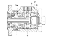
従来から図3に示す構成の回転継手が知られている。この構成においては、回転軸1の外周が継手本体2に所定間隔をおいて回転軸受3a、3bを介在して相対回転自在に装着され、両回転軸受3a、3b間にスリーブ4が装着されている。この回転継手においては、複数系統の流体を回転軸1から継手本体2に又は継手本体2から回転軸1に流通するようになっている。スリーブ4と継手本体2間は、シール部材5により流路間を遮断するように密封状態に弾性支持されており、スリーブ4の内径側は回転軸1と微少隙間を持って嵌合し、所謂メタルシール構造とされている。
Conventionally, a rotary joint having a configuration shown in FIG. 3 is known. In this configuration, the outer periphery of the
このメタルシール構造においては、通常の隙間量(クリアランス)としては、5/1000mm〜1/100mmといった微小量であるため、回転中に何らかの偏荷重がスリーブ4へ加わったりすると、回転軸1の外周面とスリーブ4の内周面とが接触し、両者間にかじり(喰い付き)現象が発生し、作動不良を生じ使用不能を引き起こす虞れがある。
In this metal seal structure, the normal gap amount (clearance) is a minute amount such as 5/1000 mm to 1/100 mm. Therefore, if some unbalanced load is applied to the
この場合に、部品精度を高めかつ組み立て精度を向上させても、なかなか均一な製品精度が得られず、より構造を簡略化して、コストダウンをする必要が生じている。 In this case, even if the component accuracy is improved and the assembly accuracy is improved, it is difficult to obtain uniform product accuracy, and it is necessary to further simplify the structure and reduce the cost.
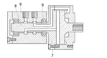
このため、スリーブ4を省略した回転継手構造も提案されており、図4に示す例えば特許文献1に記載されている構造が知られている。この回転継手構造においては、継手本体に相当する供給体6の両端において、回転軸に相当する回転体7はその突出部8との間でベアリング9を介して回転自在に保持されており、ベアリング9に挟まれた供給体6の内径側が、突出部8の外周との間で環状微小隙間を形成している。また、この特許文献1には供給体6の内径側、突出部8の外径側の部分にフッ素コーティングをすることが明示されている。
For this reason, a rotary joint structure in which the
しかしながら、この構造においては両端のベアリング9による支持部分に対して、突出部8による環状微少隙間の同芯度が重要になり、この同芯度が精度良く得られていないと、前述したようなフッ素コーティングを施しても、回転が特に高速回転になるに従って回転による振れの影響が発生し、それによって接触、かじり発生という虞れがあり、メタルシール構造における問題点は解決されていない。
However, in this structure, the concentricity of the annular minute gap by the
本発明の目的は、上述の問題点を解消し、かじり減少が発生し難いメタルシール構造の回転継手を提供することにある。 An object of the present invention is to provide a rotary joint having a metal seal structure that eliminates the above-mentioned problems and is less likely to cause galling reduction.
上記目的を達成するための本発明に係る回転継手は、回転軸を継手本体の貫通孔に挿通したメタルシール方式の回転継手において、前記回転軸をその両端において回転自在に支持する第1、第2の軸受を前記継手本体の両端側に設けた穴部内に配置し、少なくとも前記第1の軸受の内径と前記貫通孔の内径とを略同一とし、前記第1、第2の軸受の間に位置する前記回転軸の外径と前記貫通孔の内径との間をメタルシール構造としたことを特徴とする。 In order to achieve the above object, a rotary joint according to the present invention is a metal seal type rotary joint in which a rotary shaft is inserted into a through hole of a joint body, and the rotary shaft is rotatably supported at both ends thereof. The two bearings are disposed in holes provided on both ends of the joint body, at least the inner diameter of the first bearing and the inner diameter of the through hole are substantially the same, and the first and second bearings are disposed between the first and second bearings. A metal seal structure is formed between the outer diameter of the rotary shaft positioned and the inner diameter of the through hole.
本発明に係る回転継手によれば、次に列挙する利点がある。 The rotary joint according to the present invention has the following advantages.
(1)スリーブを無くして構造を簡単にできるので、コストを大幅に低減できる。(2)加工を容易にしかつ精度を高めることができ、更には組立を容易にできる。(3)組立精度、同芯度が向上するので、高速においてもメタルシール部の非接触状態が良好に保持でき長寿命化を図れる。 (1) Since the structure can be simplified without the sleeve, the cost can be greatly reduced. (2) Processing can be facilitated and accuracy can be increased, and further assembly can be facilitated. (3) Since the assembly accuracy and concentricity are improved, the non-contact state of the metal seal portion can be satisfactorily maintained even at high speed, and the life can be extended.
本発明を図1、図2に図示の実施例に基づいて詳細に説明する。 The present invention will be described in detail based on the embodiment shown in FIGS.
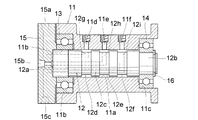
図1において、継手本体11には中心部に貫通孔11aが穿孔され、継手本体11の両端に第1、第2の軸受13、14が挿着されている。軸受13、14の径は相異し、第1の軸受13の方が内径、外径共に大きい径とされ、第1の軸受13の内径は継手本体11の貫通孔11aの内径寸法とほぼ同一に形成されており、第2の軸受14の内径は貫通孔11aの内径よりも小さくされている。
In FIG. 1, a
第1、第2の軸受13、14は継手本体11の両端に設けられた大径穴11b、11c内にそれぞれ取り付けられ、大径穴11b、11cの径は軸受13、14の外径寸法よりも稍々大きく形成されている。大径穴11b、11cの間の貫通孔11aの内径側から継手本体11の外径側に、所定間隔で流体通路11d、11e、11fが形成され、これらの外径側はねじ穴とされている。
The first and
貫通孔11aに回転軸12が挿通され、回転軸12の両端は第1、第2の軸受13、14のそれぞれの内径に嵌合される第1、第2の軸端部12a、12bとされ、第1の軸端部12aの外側にエンドカバー15が接続され、第2の軸端部12bの外側に止め輪16が設けられている。両軸端部12a、12bの間の貫通孔11aとの間でメタルシール構造を構成する軸中部12cが形成されており、この軸中部12cは第1の軸端部12aよりも稍々小径とされている。
The
継手本体11の流体通路11d、11e、11fに対向した軸中部12cには環状溝12d、12e、12fが形成されている。回転軸12には、これらの環状溝12d、12e、12fに面して通孔12g、12h、12iが形成され、これらの通孔12g、12h、12iは軸芯中心に向けて穿孔され、途中から軸芯方向に屈曲され、第1の軸端部12aの側面に開口し、エンドカバー15に設けられた孔部と接続され、エンドカバー15の外面に接続口15a、15b、15cとして開口されている。
An
この構成により、軸受本体11の流体通路11d、11e、11fは、回転軸12の通孔12g、12h、12iを介してエンドカバー15の接続口15a、15b、15cと導通することにより、貫通孔11aと回転軸12との間はメタルシール構造とされているために、貫通孔11aと回転軸12間で流体が漏出することもなく、各通路の独立性は保持される。
With this configuration, the
また、この構成により、回転軸12の第1の軸端部12aを基準にして、第2の軸端部12b、軸中部12cをワンチャックで研削精密加工することができ、更に継手本体11の貫通孔11aを第1の軸受13の内径と同一に形成することで、組立精度を高めることができる。
Further, with this configuration, the second
この回転軸受の組立に際して使用する環状の組立治具の外径は、第1の軸受13の内径つまり継手本体11の貫通孔11aの内径寸法と同一に形成され、かつ先端側の軸径は第2の軸受14の内径寸法に形成されている。この組立治具を継手本体11の貫通孔11aに挿入し、この状態で第1、第2の軸受13、14を継手本体11の大径穴11b、11cに挿入する。
The outer diameter of the annular assembly jig used for assembling the rotary bearing is the same as the inner diameter of the first bearing 13, that is, the inner diameter of the
第1、第2の軸受13、14は組立治具側の外径で保持されており、この状態で軸受13、14の外径と大径穴11b、11cとの間には隙間が生じているが、この隙間部分に接着剤を流し込み軸受13、14を固定することによって、軸受13、14の内径と継手本体11の貫通孔11aとが同芯状に固定される。
The first and
その後に組立治具を抜いて、回転軸12を第1の軸受13側から挿入することで、軸受本体11と固定軸12を正確に所定位置に組立てることができる。
Thereafter, the assembly jig is removed, and the
また、メタルシール部についても、回転軸12の第1の軸端部12aに対して軸中部12cを精密加工ができるので、継手本体11の貫通孔11aとの隙間量を正確に設定することができる。
In addition, since the
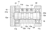
なお実施例1では、両端の第1、第2の軸受13、14の大きさを変えたが、同じ大きさの軸受に構成しても、基本的には同じである。
In the first embodiment, the sizes of the first and
即ち、図2の実施例2に示すように、両軸受21、22の内径21a、22a同士は継手本体11の貫通孔11aの内径と同一に形成することで、先の実施例1と同様な効果が得られる。
That is, as shown in the second embodiment of FIG. 2, the
11 継手本体
11a 貫通孔
11b、11c 大径孔
11d、11e、11f 流体通路
12 回転軸
12a、12b 軸端部
12c 軸中部
12d、12e、12f 環状溝
12g、12h、12i 通孔
13、14、21、22 軸受
15 エンドカバー
11
Claims (5)
Priority Applications (1)
| Application Number | Priority Date | Filing Date | Title |
|---|---|---|---|
| JP2004110857A JP2005291455A (en) | 2004-04-05 | 2004-04-05 | Rotary joint |
Applications Claiming Priority (1)
| Application Number | Priority Date | Filing Date | Title |
|---|---|---|---|
| JP2004110857A JP2005291455A (en) | 2004-04-05 | 2004-04-05 | Rotary joint |
Publications (1)
| Publication Number | Publication Date |
|---|---|
| JP2005291455A true JP2005291455A (en) | 2005-10-20 |
Family
ID=35324601
Family Applications (1)
| Application Number | Title | Priority Date | Filing Date |
|---|---|---|---|
| JP2004110857A Pending JP2005291455A (en) | 2004-04-05 | 2004-04-05 | Rotary joint |
Country Status (1)
| Country | Link |
|---|---|
| JP (1) | JP2005291455A (en) |
Cited By (3)
| Publication number | Priority date | Publication date | Assignee | Title |
|---|---|---|---|---|
| CN103100970A (en) * | 2013-01-31 | 2013-05-15 | 西安工业大学 | Rotating sealing device capable of polishing with air |
| KR101456296B1 (en) * | 2007-12-27 | 2014-11-04 | 두산인프라코어 주식회사 | A joint structure for a cutting oil in a rear part of a spindle for a machining apparatus |
| DE202016101447U1 (en) | 2016-03-16 | 2017-06-19 | Zasche handling GmbH | Rotary union |
Citations (5)
| Publication number | Priority date | Publication date | Assignee | Title |
|---|---|---|---|---|
| JPS6319488A (en) * | 1986-07-11 | 1988-01-27 | 株式会社 北川鉄工所 | Rotary joint for fluid |
| JPH01168090U (en) * | 1988-05-18 | 1989-11-27 | ||
| JPH0798085A (en) * | 1993-04-30 | 1995-04-11 | Kuroda Precision Ind Ltd | Combined rotary joint device |
| JP2002130308A (en) * | 2000-10-17 | 2002-05-09 | Nsk Ltd | Method of assembling bearing device |
| JP2003056719A (en) * | 2001-08-08 | 2003-02-26 | Thk Co Ltd | Dynamic pressure seal device and rotary joint device using the same |
-
2004
- 2004-04-05 JP JP2004110857A patent/JP2005291455A/en active Pending
Patent Citations (5)
| Publication number | Priority date | Publication date | Assignee | Title |
|---|---|---|---|---|
| JPS6319488A (en) * | 1986-07-11 | 1988-01-27 | 株式会社 北川鉄工所 | Rotary joint for fluid |
| JPH01168090U (en) * | 1988-05-18 | 1989-11-27 | ||
| JPH0798085A (en) * | 1993-04-30 | 1995-04-11 | Kuroda Precision Ind Ltd | Combined rotary joint device |
| JP2002130308A (en) * | 2000-10-17 | 2002-05-09 | Nsk Ltd | Method of assembling bearing device |
| JP2003056719A (en) * | 2001-08-08 | 2003-02-26 | Thk Co Ltd | Dynamic pressure seal device and rotary joint device using the same |
Cited By (3)
| Publication number | Priority date | Publication date | Assignee | Title |
|---|---|---|---|---|
| KR101456296B1 (en) * | 2007-12-27 | 2014-11-04 | 두산인프라코어 주식회사 | A joint structure for a cutting oil in a rear part of a spindle for a machining apparatus |
| CN103100970A (en) * | 2013-01-31 | 2013-05-15 | 西安工业大学 | Rotating sealing device capable of polishing with air |
| DE202016101447U1 (en) | 2016-03-16 | 2017-06-19 | Zasche handling GmbH | Rotary union |
Similar Documents
| Publication | Publication Date | Title |
|---|---|---|
| US7654744B2 (en) | Fluid dynamic bearing mechanism for a motor | |
| JPH1113764A (en) | Hydrostatic air bearing | |
| WO2013002252A1 (en) | Rolling bearing | |
| US7391139B2 (en) | Spindle motor and rotation apparatus | |
| JPH1151069A (en) | Double seal bearing | |
| KR20050039660A (en) | Radial rotary transfer assembly | |
| JP2016086611A (en) | Stator core cooling structure for rotary electric machine | |
| JP2010151292A (en) | Tilting-pad bearing | |
| JPH1182486A (en) | Fluid bearing | |
| JP4451771B2 (en) | Spindle motor | |
| JP2005291455A (en) | Rotary joint | |
| US7550887B2 (en) | Spindle motor and method of manufacturing spindle motor | |
| JP3547844B2 (en) | Fluid dynamic pressure bearing | |
| CN100485211C (en) | Viscoelastic frictional damping device in use for reducing vibration of high-speed rotor system | |
| JP2004190855A (en) | Spindle motor | |
| JP2000205469A (en) | Rotary joint | |
| JP2001116046A (en) | Dynamic pressure bearing device | |
| JP2001041242A (en) | Static pressure gas bearing device | |
| JP5026301B2 (en) | Rolling bearing unit and manufacturing method thereof | |
| JPH06173952A (en) | Static pressure fluid bearing | |
| JP5225700B2 (en) | Rolling bearing unit | |
| JP7003683B2 (en) | Angular contact ball bearings, bearing devices, and spindle devices | |
| JP5230020B2 (en) | Spindle motor for hard disk drive | |
| JP2006077835A (en) | Sealing device | |
| JP4573230B2 (en) | Rotary joint for fluid supply |
Legal Events
| Date | Code | Title | Description |
|---|---|---|---|
| A621 | Written request for application examination |
Free format text: JAPANESE INTERMEDIATE CODE: A621 Effective date: 20070330 |
|
| A711 | Notification of change in applicant |
Free format text: JAPANESE INTERMEDIATE CODE: A711 Effective date: 20080929 |
|
| A521 | Written amendment |
Free format text: JAPANESE INTERMEDIATE CODE: A821 Effective date: 20080930 |
|
| A521 | Written amendment |
Free format text: JAPANESE INTERMEDIATE CODE: A523 Effective date: 20081128 |
|
| A521 | Written amendment |
Free format text: JAPANESE INTERMEDIATE CODE: A821 Effective date: 20081128 |
|
| A521 | Written amendment |
Free format text: JAPANESE INTERMEDIATE CODE: A523 Effective date: 20090217 |
|
| A521 | Written amendment |
Free format text: JAPANESE INTERMEDIATE CODE: A821 Effective date: 20090217 |
|
| A977 | Report on retrieval |
Free format text: JAPANESE INTERMEDIATE CODE: A971007 Effective date: 20091030 |
|
| A131 | Notification of reasons for refusal |
Free format text: JAPANESE INTERMEDIATE CODE: A131 Effective date: 20091110 |
|
| A02 | Decision of refusal |
Free format text: JAPANESE INTERMEDIATE CODE: A02 Effective date: 20100330 |