WO2024014216A1 - 水中探知装置、送信条件の最適化方法、およびプログラム - Google Patents
水中探知装置、送信条件の最適化方法、およびプログラム Download PDFInfo
- Publication number
- WO2024014216A1 WO2024014216A1 PCT/JP2023/021893 JP2023021893W WO2024014216A1 WO 2024014216 A1 WO2024014216 A1 WO 2024014216A1 JP 2023021893 W JP2023021893 W JP 2023021893W WO 2024014216 A1 WO2024014216 A1 WO 2024014216A1
- Authority
- WO
- WIPO (PCT)
- Prior art keywords
- transmission
- voltage
- current
- detection device
- control circuit
- Prior art date
- Legal status (The legal status is an assumption and is not a legal conclusion. Google has not performed a legal analysis and makes no representation as to the accuracy of the status listed.)
- Ceased
Links
Images




Classifications
-
- G—PHYSICS
- G01—MEASURING; TESTING
- G01S—RADIO DIRECTION-FINDING; RADIO NAVIGATION; DETERMINING DISTANCE OR VELOCITY BY USE OF RADIO WAVES; LOCATING OR PRESENCE-DETECTING BY USE OF THE REFLECTION OR RERADIATION OF RADIO WAVES; ANALOGOUS ARRANGEMENTS USING OTHER WAVES
- G01S15/00—Systems using the reflection or reradiation of acoustic waves, e.g. sonar systems
- G01S15/88—Sonar systems specially adapted for specific applications
- G01S15/96—Sonar systems specially adapted for specific applications for locating fish
-
- G—PHYSICS
- G01—MEASURING; TESTING
- G01S—RADIO DIRECTION-FINDING; RADIO NAVIGATION; DETERMINING DISTANCE OR VELOCITY BY USE OF RADIO WAVES; LOCATING OR PRESENCE-DETECTING BY USE OF THE REFLECTION OR RERADIATION OF RADIO WAVES; ANALOGOUS ARRANGEMENTS USING OTHER WAVES
- G01S15/00—Systems using the reflection or reradiation of acoustic waves, e.g. sonar systems
- G01S15/88—Sonar systems specially adapted for specific applications
- G01S15/89—Sonar systems specially adapted for specific applications for mapping or imaging
-
- G—PHYSICS
- G01—MEASURING; TESTING
- G01S—RADIO DIRECTION-FINDING; RADIO NAVIGATION; DETERMINING DISTANCE OR VELOCITY BY USE OF RADIO WAVES; LOCATING OR PRESENCE-DETECTING BY USE OF THE REFLECTION OR RERADIATION OF RADIO WAVES; ANALOGOUS ARRANGEMENTS USING OTHER WAVES
- G01S7/00—Details of systems according to groups G01S13/00, G01S15/00, G01S17/00
- G01S7/52—Details of systems according to groups G01S13/00, G01S15/00, G01S17/00 of systems according to group G01S15/00
- G01S7/52004—Means for monitoring or calibrating
-
- G—PHYSICS
- G01—MEASURING; TESTING
- G01S—RADIO DIRECTION-FINDING; RADIO NAVIGATION; DETERMINING DISTANCE OR VELOCITY BY USE OF RADIO WAVES; LOCATING OR PRESENCE-DETECTING BY USE OF THE REFLECTION OR RERADIATION OF RADIO WAVES; ANALOGOUS ARRANGEMENTS USING OTHER WAVES
- G01S7/00—Details of systems according to groups G01S13/00, G01S15/00, G01S17/00
- G01S7/52—Details of systems according to groups G01S13/00, G01S15/00, G01S17/00 of systems according to group G01S15/00
- G01S7/523—Details of pulse systems
- G01S7/524—Transmitters
-
- G—PHYSICS
- G01—MEASURING; TESTING
- G01S—RADIO DIRECTION-FINDING; RADIO NAVIGATION; DETERMINING DISTANCE OR VELOCITY BY USE OF RADIO WAVES; LOCATING OR PRESENCE-DETECTING BY USE OF THE REFLECTION OR RERADIATION OF RADIO WAVES; ANALOGOUS ARRANGEMENTS USING OTHER WAVES
- G01S7/00—Details of systems according to groups G01S13/00, G01S15/00, G01S17/00
- G01S7/52—Details of systems according to groups G01S13/00, G01S15/00, G01S17/00 of systems according to group G01S15/00
- G01S7/56—Display arrangements
- G01S7/62—Cathode-ray tube displays
-
- H—ELECTRICITY
- H04—ELECTRIC COMMUNICATION TECHNIQUE
- H04R—LOUDSPEAKERS, MICROPHONES, GRAMOPHONE PICK-UPS OR LIKE ACOUSTIC ELECTROMECHANICAL TRANSDUCERS; ELECTRIC HEARING AIDS; PUBLIC ADDRESS SYSTEMS
- H04R1/00—Details of transducers, loudspeakers or microphones
- H04R1/44—Special adaptations for subaqueous use, e.g. for hydrophone
Definitions
- the present invention relates to an underwater detection device that detects underwater conditions, and a transmission condition optimization method that automatically optimizes the transmission conditions of an ultrasonic transducer for transmitting ultrasonic waves into the water.
- underwater detection devices that detect underwater conditions are known.
- ultrasonic waves are transmitted underwater and the reflected waves are received.
- Echo data is generated according to the intensity of the received reflected wave, and an echo image is displayed based on the generated echo data.
- a new control device may be connected to the existing transducer.
- the new control device requires setting the transmission conditions for the ultrasonic transducer included in the transducer. In this case, it is necessary to separately check the impedance characteristics of the ultrasonic transducer in the transducer attached to the bottom of the ship using a measuring device. Such work is quite complicated.
- This problem can be solved by having the transducer retain information regarding the ultrasonic transducer in advance. For example, information regarding the characteristics of the ultrasonic transducer, such as the resonant frequency of the ultrasonic transducer, allowable input power, transmission/reception sensitivity, and impedance, is stored in the storage section of the transducer. When a new control device is connected to this transducer, the above information is read from the storage section of the transducer. Thereby, it is possible to obtain the impedance characteristics of the ultrasonic transducer without separately measuring it with a measuring device.
- information regarding the characteristics of the ultrasonic transducer such as the resonant frequency of the ultrasonic transducer, allowable input power, transmission/reception sensitivity, and impedance
- the same type of transducer holds the same information. Therefore, if there are individual differences between the transducers, it is not possible to set optimal transmission conditions for each transducer in the underwater detection device. Further, the impedance characteristics of the ultrasonic transducer may change depending on the underwater environment such as the temperature of the water. The above configuration cannot cope with such changes in characteristics.
- the present invention provides an underwater detection device, a method for optimizing transmission conditions, and a program that can easily and accurately optimize the transmission conditions of an ultrasonic transducer included in a transducer.
- the purpose is to
- a first aspect of the present invention relates to an underwater detection device.
- the underwater detection device includes a transmitting circuit that supplies a transmitting voltage and a transmitting current to the ultrasonic transducer, a transmitting voltage measuring circuit that measures the transmitting voltage, and a transmitting current measuring circuit that measures the transmitting current. , a control circuit that optimizes transmission conditions of the ultrasonic transducer based on the transmission voltage and transmission current measured by the transmission voltage measurement circuit and the transmission current measurement circuit, respectively.
- the transmission voltage and transmission current of the ultrasonic transducer included in the transducer can be measured by the transmission voltage measurement circuit and the transmission current measurement circuit, it is possible to measure the transmission voltage and transmission current of the ultrasonic transducer included in the transducer.
- the transmission conditions of the acoustic wave transducer can be optimized.
- the actual transmission voltage and current of the ultrasonic transducer included in the transducer can be measured, allowing underwater detection to determine the optimal transmission conditions for the ultrasonic transducer. Can be set on the device.
- the underwater detector can determine the optimal transmitting conditions according to the underwater environment. Can be set to Therefore, the transmission conditions of the ultrasonic transducer can be easily and accurately optimized.
- control circuit performs the control circuit based on the transmission voltage and the transmission current respectively measured by the transmission voltage measurement circuit and the transmission current measurement circuit under actual usage conditions. It may be configured to optimize transmission conditions of the ultrasonic transducer.
- the transmission conditions of the ultrasonic transducer are optimized under the conditions of actual use. Can transmit waves.
- actual usage conditions refer to, for example, the rated value of the transmission current determined by the hardware constraints of the transmission system including the transmission circuit, the rated power of the ultrasonic transducer, etc. This refers to certain restrictions required of underwater detection equipment.
- control circuit may be configured to optimize the transmission voltage as optimization of the transmission condition.
- control circuit increases the transmission voltage within a range where the transmission power calculated from the transmission voltage and the transmission current and the transmission current do not exceed their respective upper limit values. It may be configured to perform voltage optimization.
- the transmission voltage as high as possible can be set as the optimum value of the transmission voltage within a range where the transmission power and the transmission current do not exceed their respective upper limit values.
- control circuit adjusts the transmission voltage to a predetermined value from the current transmission voltage on the condition that the transmission power and the transmission current measured by the current transmission voltage are less than the respective upper limit values. It may be configured to repeatedly perform control to increase only the voltage.
- the transmission power and transmission current can be gradually brought closer to their respective upper limit values, and the transmission voltage can be smoothly set to the highest possible voltage value.
- the control circuit when the transmission power and the transmission current measured by the current transmission voltage exceed the respective upper limit values, the control circuit reduces the transmission voltage by a predetermined voltage to reach the upper limit value.
- the transmission voltage may be controlled to return to the transmission voltage immediately before exceeding the voltage.
- control circuit optimizes the transmission voltage when the condition is satisfied after performing control to reduce the transmission voltage by a predetermined voltage and return it to the transmission voltage immediately before exceeding the upper limit value.
- the transmission voltage can be set to a voltage value as high as possible within a range where the transmission power and transmission current do not exceed their respective upper limits.
- the predetermined voltage may be set to a voltage with a minimum width that allows the transmission voltage to be increased or decreased.
- control circuit increases the transmission voltage by the predetermined voltage within a range in which the transmission power and the transmission current do not exceed the respective upper limit values at a plurality of transmission frequencies used for transmitting the ultrasonic waves.
- the control may be configured to execute repeatedly.
- control circuit may be configured to optimize the transmission frequency as the optimization of the transmission conditions.
- control circuit acquires the transmission voltage and the transmission current from the transmission voltage measurement circuit and the transmission current measurement circuit while changing the frequency of the transmission signal, and the transmission voltage acquired for each frequency. And an equivalent parallel resistance is calculated from the transmission current, and the frequency at which the value of the calculated equivalent parallel resistance is the minimum is obtained as the optimum value of the transmission frequency.
- a transmission frequency that can most efficiently apply transmission power to the ultrasonic transducer can be set in the underwater detection device.
- control circuit further transmits a transmission signal for optimizing the transmission conditions to the transmission circuit in one sequence of transmitting and receiving the ultrasonic waves for detection. It can be configured to output to
- control circuit may be configured to cause the transmission circuit to output a transmission signal for optimizing the transmission conditions at a timing different from the transmission of the ultrasonic waves for detection.
- transmission signals for optimization can be output to the transmission circuit in parallel, and the transmission voltage and transmission current can be measured by the transmission voltage measurement circuit and the transmission current measurement circuit. Therefore, transmission conditions can be optimized in real time during actual underwater detection operations.
- a second aspect of the present invention relates to a transmission condition optimization method for automatically optimizing the transmission conditions of an ultrasonic transducer for transmitting ultrasonic waves into water.
- the method for optimizing transmission conditions according to this aspect includes measuring the transmission voltage and transmission current supplied to the ultrasonic transducer during actual use, and determining whether the ultrasonic wave Optimize the transducer transmission conditions.
- a third aspect of the present invention includes a transmitting circuit that supplies a transmitting voltage and a transmitting current to an ultrasonic transducer, a transmitting voltage measuring circuit that measures the transmitting voltage, a transmitting current measuring circuit that measures the transmitting current,
- the present invention relates to a program that causes a control circuit of an underwater detection device equipped with the following to execute a predetermined function.
- the program according to this aspect has a function of optimizing the transmission conditions of the ultrasonic transducer based on the transmission voltage and the transmission current measured by the transmission voltage measurement circuit and the transmission current measurement circuit during actual use. Execute.
- the present invention provides an underwater detection device, a method for optimizing transmission conditions, and a program that can easily and accurately optimize the transmission conditions of an ultrasonic transducer included in a transducer. be able to.
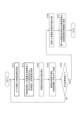
- FIG. 1 is a diagram showing a usage pattern of a fish finding device according to an embodiment.
- FIG. 2 is a block diagram showing the configuration of the fish finding device according to the embodiment.
- FIG. 3 is a flowchart illustrating basic processing for optimizing the transmission conditions of the ultrasonic transducer according to the embodiment.
- FIG. 4 is a flowchart showing processing for optimizing the transmission frequency according to the embodiment.
- FIG. 5(a) is a graph showing an example of the frequency-impedance characteristic of the ultrasonic transducer according to the embodiment.
- FIG. 5(b) is a graph showing an example of frequency-phase characteristics of the ultrasonic transducer according to the embodiment.
- FIG. 5(c) is a graph showing an example of the frequency-equivalent parallel resistance characteristic of the ultrasonic transducer according to the embodiment.
- FIG. 6 is a flowchart illustrating processing for optimizing transmission voltage according to the embodiment.
- FIG. 7 is a flowchart illustrating processing for optimizing transmission voltage according to modification example 1.
- FIG. 8 is a diagram schematically showing a test period added to one sequence in order to perform transmission frequency optimization processing according to modification example 2.
- FIG. 9 is a flowchart illustrating processing for optimizing the transmission frequency according to modification example 2.
- FIG. 10 is a diagram schematically showing a test period added to one sequence in order to perform transmission voltage optimization processing according to modification example 2.
- FIG. 11 is a flowchart illustrating processing for optimizing transmission voltage according to modification example 2.
- a fish detection device is shown as an example of an underwater detection device.
- FIG. 1 is a diagram showing how the fish finding device is used.
- a transducer 2 is installed on the bottom of a ship 1, and a transmission beam 3 (ultrasonic wave) is transmitted from the transducer 2 into the water.
- the transmission beam 3 has a conical shape with a small apex angle, and is transmitted in a pulsed manner in a vertically downward direction.
- the transmitted beam 3 is reflected by the water bottom 4 and the school of fish 5, and the reflected wave (echo) is received by the transducer 2. Echo data in which the signal strength (echo strength) of the received signal is distributed in the detection range in the water depth direction is generated by the received signal of the reflected wave based on one transmission of the transmission beam 3.
- an echo image showing the distribution of signal intensity (echo intensity) in the water depth direction is generated.
- the echo image includes the intensity distribution of echoes from each target.
- the generated underwater echo image is displayed on a display unit installed in the wheelhouse of the ship 1 or the like. This allows the user to confirm underwater targets (water bottom 4, fish school 5, etc.).
- FIG. 2 is a block diagram showing the configuration of the fish finding device 100.
- the fish finding device 100 includes a control circuit 101, a memory 102, a transmitting circuit 103, a receiving circuit 104, a switching circuit 105, an input section 106, a display section 107, and a transmitting voltage measurement device. It includes a circuit 108, a transmission current measurement circuit 109, and the transducer 2 shown in FIG.
- the control circuit 101, memory 102, transmission circuit 103, reception circuit 104, switching circuit 105, input section 106, display section 107, transmission voltage measurement circuit 108, and transmission current measurement circuit 109 are installed in the wheelhouse of the ship 1, etc. .
- the configuration other than the transducer 2 may be integrated into one housing, or some components such as the display section 107 may be separated.
- the switching circuit 105 is communicably connected to the transducer 2 via a signal cable.
- the transducer 2 includes a wave transmitting element used for transmitting ultrasonic waves and a wave receiving element used for receiving ultrasonic waves.
- the wave transmitting element and the wave receiving element of the transducer 2 are constituted by one ultrasonic transducer 21.
- the transmission circuit 103 generates a transmission signal for driving the ultrasonic transducer 21 from the control signal input from the control circuit 101, and transmits the generated transmission signal to the ultrasonic wave of the transducer 2 via the switching circuit 105. Output to the vibrator 21.
- control circuit 101 outputs a frequency control signal that has a rectangular amplitude at a predetermined control frequency and a voltage control signal that defines a control voltage to the transmission circuit 103 as the above-mentioned control signals.
- the transmission circuit 103 generates a transmission signal having a frequency similar to the control frequency of the input frequency control signal and a transmission voltage similar to the control voltage of the input voltage control signal.
- the control circuit 101 outputs the generated control signal to the ultrasound transducer 21 via the switching circuit 105.
- the ultrasonic transducer 21 transmits ultrasonic waves (transmission beam 3) into the water based on the input transmission signal. Further, the ultrasonic transducer 21 receives reflected waves of the transmitted ultrasonic waves, and outputs a received signal having a magnitude corresponding to the intensity of the reflected waves to the receiving circuit 104 via the switching circuit 105. The switching circuit 105 switches transmission and reception of signals to and from the ultrasonic transducer 21 .
- the receiving circuit 104 includes a filter that extracts the frequency component of the transmitted wave from the received signal from the ultrasonic transducer 21, and an amplification circuit that amplifies the received signal.
- the receiving circuit 104 generates echo data indicating echo intensity for each depth based on the received signal of the frequency components extracted by the filter. Specifically, the receiving circuit 104 generates, as echo data, data that associates the elapsed time from the timing of transmitting the ultrasound (transmission beam 3) with the intensity of the reflected wave, and uses the generated echo data as echo data. It is output to the control circuit 101.
- the elapsed time from the timing of transmitting the ultrasound corresponds to the depth.
- the intensity of the reflected wave attenuates as the depth increases. Therefore, the receiving circuit 104 corrects the intensity of the reflected wave that attenuates depending on the elapsed time, and outputs the echo data with the intensity corrected to the control circuit 101.
- the control circuit 101 is composed of an arithmetic processing circuit such as a CPU or an integrated circuit such as an FPGA.
- the memory 102 is composed of ROM, RAM, hard disk, etc.
- the memory 102 stores various programs. These programs include a program that causes the control circuit 101 (computer) to execute a function of processing echo data to generate an image and a function of optimizing the transmission conditions of the ultrasound transducer 21.
- the memory 102 is used as a work area during processing by the control circuit 101.
- the control circuit 101 controls each section according to a program stored in the memory 102. The process of optimizing the transmission conditions of the ultrasonic transducer 21 will be explained later with reference to FIGS. 3 to 6.
- the input unit 106 is comprised of input means such as a mouse and a keyboard, and accepts input from the user.
- the input unit 106 may be a touch panel integrated into the display unit 107.
- the display unit 107 is configured with a display device such as a CRT monitor or a liquid crystal panel, and displays images generated by the control circuit 101. As described above, the display unit 107 displays an echo image generated based on echo data.
- the control circuit 101 acquires echo data in which depth and echo intensity are associated with each other at each transmission timing of the ultrasound (transmission beam 3).
- the control circuit 101 generates an echo image based on one frame of continuously acquired echo data, and causes the display unit 107 to display the echo image.
- An echo image is sometimes called an echo diagram.
- An echo image is an image in which echo intensity is distributed in a coordinate area with depth and time as two axes.
- each pixel is colored or shaded in gradation according to the signal strength of the reflected wave.
- a user such as a fisherman can understand the position and range of a school of fish underwater by referring to the echo image displayed on the display unit 107.
- the transmission voltage measurement circuit 108 measures the transmission voltage supplied from the transmission circuit 103 to the ultrasound transducer 21.
- Transmission current measurement circuit 109 measures the transmission current supplied from transmission circuit 103 to ultrasound transducer 21 .
- the configurations of the transmission voltage measurement circuit 108 and the transmission current measurement circuit 109 are similar to the configurations of the transmission voltage measurement circuit and the transmission current measurement circuit used for measuring the transmission voltage and transmission current of a power supply circuit or the like.
- the transmission voltage measurement circuit 108 and the transmission current measurement circuit 109 adjust the parameters (resistance value, etc.) of each element to match the magnitude of the transmission voltage and transmission current that can be expected to be supplied to the ultrasonic transducer 21. has been adjusted.
- a process of optimizing the transmission conditions of the ultrasonic transducer 21 is performed using the transmission voltage and transmission current measured by the transmission voltage measurement circuit 108 and the transmission current measurement circuit 109.
- FIG. 3 is a flowchart showing basic processing for optimizing the transmission conditions of the ultrasonic transducer 21.
- the process shown in FIG. 3 is executed, for example, immediately after the fish finding device 100 is started, when the operation is interrupted, or by an arbitrary instruction from the user.
- this process is executed in response to an instruction from the user, generation of echo data and updating of the echo image are interrupted during this process.
- control circuit 101 controls the transmission circuit 10 while changing the control frequency and control voltage.
- a control signal is output to 3.
- the control circuit 101 causes the transmission circuit 103 to output a transmission signal while changing the transmission frequency and transmission voltage (S11).
- measured values of the transmission voltage and transmission current are output from the transmission voltage measurement circuit 108 and the transmission current measurement circuit 109 to the control circuit 101.
- the control circuit 101 acquires these measured values for each combination of transmission frequency (control frequency) and transmission voltage (control voltage) (S12). Then, the control circuit 101 optimizes the transmission conditions of the ultrasonic transducer 21 based on the acquired measured values of the transmission voltage and transmission current (S13).
- optimization of transmission conditions includes optimization of transmission frequency and transmission voltage.
- specific processing for optimizing the transmission frequency and optimizing the transmission voltage will be described.
- the range of frequencies that can be used for transmission (hereinafter referred to as "nominal band"), the initial value of the transmission voltage, the upper limit of the transmission current, and the upper limit of the transmission power are value is used.
- the initial value of the transmission voltage for example, the minimum value of the transmission voltage range (appropriate operating range) in which the transducer 2 (ultrasonic transducer 21) can properly operate in transmitting waves may be used.
- the initial value of the transmission voltage may be any other voltage value within the proper operating range.
- the upper limit value of the transmitting current is the rated value of the transmitting current defined by the hardware constraints of the transmitting system including the transmitting circuit 103, and the upper limit value of the transmitting power is the rated power of the ultrasonic transducer 21.
- the upper limit value of the transmission current may be set slightly lower than the above-mentioned rated value, and the upper limit value of the transmission power may be set slightly lower than the above-mentioned rated value.
- These values are input by a service person via the input unit 106, for example, when installing the fish finding device 100 (including when replacing components other than the transducer 2).
- the service person for example, refers to a correspondence table in which these values are mapped to the model of the transducer 2 and the model of the fish finder 100, and determines the target transducer 2 and fish finder 100. Enter the value corresponding to 100.
- the upper limit value of the transmission current (rated current of the transmission system) may be stored in the memory 102 in advance.
- FIG. 4 is a flowchart showing the process for optimizing the transmission frequency.
- the control circuit 101 sets the target frequency to a predetermined frequency within the nominal band (S101).
- the control circuit 101 outputs a control signal according to the set target frequency and the initial value of the transmission voltage to the transmission circuit 103, and transmits the measured value of the transmission voltage and the measured value of the transmission current to the transmission voltage measurement circuit 108 and the transmission current measurement circuit 108. It is acquired from the circuit 109 (S102).
- the control circuit 101 calculates the equivalent parallel resistance from the acquired transmission voltage measurement value and transmission current measurement value (S103).
- step S103 the control circuit 101 calculates the impedance Z of the ultrasonic transducer 21 from the measured value Vm of the transmission voltage and the measured value Im of the transmission current using the following equation (1).
- control circuit 101 obtains the phase ⁇ between the control voltage and the transmission voltage, and calculates the value of the equivalent parallel resistance Rp from the obtained phase ⁇ and the impedance Z using the following formula.
- the control circuit 101 stores the calculated value of the equivalent parallel resistance Rp in the memory 102 in association with the target frequency set in step S101 (S104).
- the control circuit 101 determines whether the processing of steps S101 to S104 has been completed for all frequencies set at predetermined frequency intervals within the nominal band (S105). If the determination in step S105 is NO, the control circuit 101 sets the next frequency within the nominal band as the target frequency in step S101, and similarly executes the processes in steps S102 to S104. The control circuit 101 repeatedly executes this process until the determination in step S105 becomes YES.
- the control circuit 101 acquires the equivalent parallel resistance of each target frequency stored in the memory 102. The values of are compared with each other (S106). Then, the control circuit 101 sets the target frequency at which the minimum equivalent parallel resistance value among these equivalent parallel resistance values is obtained as the optimum value of the transmission frequency (S107). Thereby, the control circuit 101 ends the process of FIG.
- all equivalent parallel resistance values for all target frequencies are stored in the memory 102, and then all stored equivalent parallel resistance values are compared to determine the minimum equivalent parallel resistance value.
- the method for extracting the value of the minimum equivalent parallel resistance is not limited to this.
- the control circuit 101 each time the control circuit 101 calculates the value of the equivalent parallel resistance, the control circuit 101 compares the value of the equivalent parallel resistance stored in the memory 102 as the minimum so far with the calculated value of the equivalent parallel resistance, If the calculated value of the equivalent parallel resistance is smaller, the value of the calculated equivalent parallel resistance is stored in the memory 102 instead of the value of the equivalent parallel resistance that was the minimum until then.
- the value of the equivalent parallel resistance and its target frequency may be obtained.
- FIGS. 5(a) to 5(c) are graphs showing examples of the impedance Z, phase ⁇ , and equivalent parallel resistance Rp of each target frequency calculated in step S103 of FIG. 4, respectively.
- FIG. 5(a) shows an example of the frequency-impedance characteristic of the ultrasonic transducer 21
- FIG. 5(b) shows an example of the frequency-phase characteristic of the ultrasonic transducer 21
- 5(c) shows an example of the frequency-equivalent parallel resistance characteristic of this ultrasonic transducer 21.
- the nominal band is set to about 150 to 240 kHz.
- the impedance characteristics in FIG. 5(a) are calculated by applying the measured value Vm of the transmitted voltage and the measured value Im of the transmitted current obtained at each target frequency to the above formula (1). be.
- the equivalent parallel resistance characteristic in FIG. 5(c) is calculated by using the above equation (2) by calculating the impedance Z value of each target frequency in FIG. 5(a) and the phase ⁇ of each target frequency in FIG. 5(b). It was calculated by applying it to
- the value of the equivalent parallel resistance Rp is minimum near 160 kHz. Therefore, in this example, 160 kHz is set as the optimal value for the transmission frequency.
- the transmission power of the ultrasonic transducer 21 can be increased most efficiently. Therefore, by setting the frequency at which the equivalent parallel resistance Rp is minimum as the optimum value of the transmission frequency through the process shown in FIG. 4, ultrasonic waves can be transmitted most efficiently.
- FIG. 6 is a flowchart showing the process for optimizing the transmission voltage.
- the control circuit 101 sets the transmission frequency to the frequency optimized by the process of FIG. 4 (S201), and further sets the transmission voltage to the initial value (S202).
- the initial value is the minimum value of the proper operating range of the transmission voltage, as described above.
- the control circuit 101 outputs a control signal according to the set transmission frequency and transmission voltage to the transmission circuit 103, causes the transmission circuit 103 to output a transmission signal according to the transmission frequency and transmission voltage, and adjusts the transmission voltage and transmission current.
- the measured value of is acquired from the transmission voltage measurement circuit 108 and the transmission current measurement circuit 109 (S203).
- the control circuit 101 determines whether the acquired transmission current exceeds the upper limit value (S204). As described above, this upper limit value is the rated value of the transmission current defined by the hardware constraints of the transmission system including the transmission circuit 103. If the transmission current does not exceed the upper limit (S204: NO), the control circuit 101 determines whether the transmission power calculated from the acquired transmission voltage and transmission current exceeds the upper limit (S205). This upper limit value is the rated power of the ultrasonic transducer 21, as described above.
- the control circuit 101 determines whether the transmission voltage has converged to the maximum allowable value (S206). That is, after the transmission voltage is reduced by a predetermined voltage in step S208, the control circuit 101 determines whether the determination in step S205 is NO and the process moves to step S206.
- step S206 If the determination in step S206 is NO, that is, if the transmission voltage has not yet been reduced in step S208, the control circuit 101 increases the current transmission voltage by a predetermined voltage by increasing the current control voltage by a predetermined voltage. It is increased (S209), and the process returns to step S203.
- the predetermined voltage is set, for example, to a voltage with a minimum width that allows the transmission voltage to be increased or decreased. That is, the predetermined voltage is set to a voltage corresponding to one step when increasing/decreasing the transmission voltage in steps. Note that the transmission frequency is maintained at the optimum value set in step S201.
- the control circuit 101 increases the transmission voltage by a predetermined voltage until the determination in either step S204 or S205 becomes YES, and repeatedly executes the processing in steps S203 to S206 for each transmission voltage. . After that, if the determination in either step S204 or S205 is YES, the control circuit 101 reduces the control voltage by a predetermined voltage, thereby reducing the transmission voltage by a predetermined voltage (S208), and returns the process to step S203. .
- This predetermined voltage is set to be the same as the predetermined voltage in step S209.
- the control circuit 101 executes the processing from step S203 using the reduced transmission voltage.
- the voltage value of the transmission voltage after reduction is the voltage value that was subjected to the processing from step S203 onward, and this voltage value is the voltage value that was used in the processing from step S203 onwards, and the determination in steps S204 and S205 was NO in the processing on the previous day. . Therefore, it is normally assumed that the determinations in steps S204 and S205 will be NO this time as well. However, exceptionally, if either of the determinations in step S204 or S205 is YES, the control circuit 101 reduces the transmission voltage by a predetermined voltage again in step S208, and executes the processing from step S203 onwards. do.
- the control circuit 101 performs the determination in step S206.
- the determination in step S206 is YES.
- the transmission voltage at this time becomes the maximum voltage value within a range in which both the transmission current and the transmission power do not exceed their respective upper limits.
- step S206 If the determination in step S206 is YES, the control circuit 101 sets the transmission voltage (control voltage) at this time to the optimum value (S207), and ends the process. Thereafter, the control circuit 101 causes the transmitting circuit 103 to output a transmitting signal to which the optimum value of the transmitting frequency set by the process of FIG. 4 and the optimum value of the transmitting voltage set by the process of FIG. Transmits ultrasonic waves at the same time. Thereby, ultrasonic waves can be transmitted efficiently and appropriately, and echo images can be displayed smoothly and appropriately.
- the predetermined voltage defined in steps S208 and S209 does not necessarily have to be the minimum width voltage that allows the transmission voltage to be increased or decreased.
- the predetermined voltage in step S209 may change depending on the number of times the transmission voltage is increased. In other words, until the number of times the transmission voltage is increased reaches a predetermined number (for example, several times), the voltage for multiple steps when increasing and decreasing the transmission voltage in steps is set to the predetermined voltage, and the number of times the transmission voltage is increased is set to the predetermined voltage. After reaching a predetermined number of times (for example, several times), the voltage for one step when increasing/decreasing the transmission voltage in steps may be set to the predetermined voltage.
- predetermined voltages in steps S209 and S208 do not necessarily have to be the same.
- the predetermined voltage in step S208 may be greater than the predetermined voltage in step S209.
- the fish finding device 100 (underwater finding device) includes a transmitting circuit 103 that supplies a transmitting voltage and a transmitting current to the ultrasonic transducer 21, and a transmitting circuit 103 that supplies a transmitting voltage and a transmitting current to the ultrasonic transducer 21. It includes a transmission voltage measurement circuit 108 for measuring, a transmission current measurement circuit 109 for measuring the transmission current supplied to the ultrasonic transducer 21, and a control circuit 101. As shown in FIG. 3, the control circuit 101 optimizes the transmission conditions of the ultrasonic transducer 21 based on the transmission voltage and transmission current measured by the transmission voltage measurement circuit 108 and the transmission current measurement circuit 109, respectively. Execute (S13).
- the fish finder 100 can measure the transmitting voltage and transmitting current of the ultrasonic transducer 21 included in the transducer 2 using the transmitting voltage measuring circuit 108 and the transmitting current measuring circuit 109. , From these measurement results, the transmission conditions of the ultrasonic transducer 21 can be optimized. In addition, even if there are individual differences in the transducer 2, the actual transmission voltage and transmission current of the ultrasonic transducer 21 included in the transducer 2 can be measured, so the optimum transmission for the ultrasonic transducer 21 can be achieved. Conditions can be set in the fish finding device 100 (underwater finding device).
- the transmission voltage and current of the ultrasonic transducer 21 can be measured in that environment, so the optimal transmission conditions can be determined according to the underwater environment for fish detection. It can be set in the device 100 (underwater detection device). Therefore, the transmission conditions of the ultrasonic transducer 21 included in the transducer 2 can be easily and accurately optimized.
- the control circuit 101 controls the transmission voltage and transmission voltage measured by the transmission voltage measurement circuit 108 and the transmission current measurement circuit 109 under actual usage conditions (the upper limit values in steps S204 and S205), respectively.
- the transmission conditions of the ultrasonic transducer 21 are optimized under the conditions of actual use, so that the transmission conditions optimized for the actual use of the fish finding device 100 (underwater detection device) Waves can be properly transmitted from the ultrasonic transducer 21.
- the control circuit 101 optimizes the transmission voltage as optimization of the transmission conditions.
- the control circuit 101 increases the transmission voltage within a range where the transmission power and transmission current calculated from the transmission voltage and transmission current do not exceed their respective upper limit values (S204: NO, S205: NO). By doing so (S209), the transmission voltage is optimized.
- the transmission voltage as high as possible can be set as the optimum value of the transmission voltage within a range where the transmission power and the transmission current do not exceed their respective upper limit values.
- control circuit 101 transmits ultrasonic waves under the condition that the transmission power and transmission current measured by the current transmission voltage do not reach their respective upper limit values (S204: NO, S205: NO).
- Control (S209) for increasing the transmission voltage applied to the vibrator 21 by a predetermined voltage from the current transmission voltage is repeatedly executed. Thereby, as the transmission voltage increases, the transmission power and the transmission current can be gradually brought closer to their respective upper limit values, and the transmission voltage can be smoothly set to a voltage value as high as possible.
- control circuit 101 adjusts the transmission voltage. Control is performed to reduce the voltage by a predetermined value and return it to the transmission voltage immediately before exceeding the upper limit value (S208).
- control circuit 101 performs control to reduce the transmission voltage by a predetermined voltage and return it to the transmission voltage immediately before exceeding the upper limit value (S208), and if the conditions (S204, S205) are satisfied ( S206: YES), the optimization of the transmission voltage is completed (S207).
- the transmission voltage can be set to a voltage value as high as possible within a range where the transmission power and transmission current do not exceed their respective upper limits.
- the predetermined voltage in step S209 may be set to the minimum width voltage that allows the transmission voltage to be increased or decreased. This prevents the transmission power and transmission current from greatly exceeding their respective upper limit values when the transmission voltage is increased by a predetermined voltage value from a state where the transmission power and transmission voltage are slightly lower than their respective upper limit values. It can be suppressed. Therefore, it is possible to prevent problems such as damage to the ultrasonic transducer 21 and the transmission system from occurring due to excessive transmission power and transmission current being applied to the ultrasonic transducer 21 and the transmission system.
- the control circuit 101 optimizes the transmission frequency as optimization of the transmission conditions.
- the control circuit 101 acquires the transmission voltage and transmission current from the transmission voltage measurement circuit 108 and the transmission current measurement circuit 109 while changing the frequency of the transmission signal (S101, S102), and acquires the transmission voltage and transmission current for each frequency.
- the equivalent parallel resistance is calculated from the transmission current (S103), and the frequency at which the value of the calculated equivalent parallel resistance is the minimum is acquired as the optimum value of the transmission frequency (S107).
- FIG. 7 is a flowchart illustrating processing for optimizing transmission voltage according to Modification Example 1.
- step S204 the processing flow after step S204 is shown for convenience.
- the processing in steps S201 to S203 is similar to the corresponding processing in FIG.
- step S210 is added to the flowchart of FIG.
- the processing of steps other than step S210 is the same as the corresponding steps of FIG.
- control circuit 101 further controls the current transmission frequency at a plurality of transmission frequencies that can be used for ultrasound transmission, that is, at all frequencies in the above-mentioned nominal band. It is determined whether the transmission power and transmission current obtained from the voltage do not exceed their respective upper limit values (S210).
- step S210 the control circuit 101 causes the transmission circuit 103 to output a transmission signal at the current transmission voltage while changing the transmission frequency at predetermined frequency intervals within the nominal band, and transmits the transmission voltage and transmission current at each frequency. Obtained from voltage measurement circuit 108 and transmission current measurement circuit 109. The control circuit 101 calculates transmission power for each frequency with respect to the acquired transmission voltage and transmission current of each frequency. Then, the control circuit 101 performs the same determination as in steps S204 and S205 for the transmission current and transmission power of each frequency.
- step S210 If either the transmission current or the transmission power exceeds their respective upper limit values (the same upper limit values as in steps S204 and S205) at any frequency, the control circuit 101 makes the determination in step S210 NO and changes the current The transmission voltage is reduced by a predetermined voltage (S208). On the other hand, if neither the transmission current nor the transmission power exceeds their respective upper limit values (the upper limit values similar to steps S204 and S205) at any frequency, the determination in step S210 is set as YES, and the process returns to step S206. Proceed to. The processing after step S206 is similar to the processing shown in FIG. 6 in the above embodiment.
- the optimum value of the transmission voltage set in step S207 is determined by changing the transmission frequency from the optimum value set by the process of FIG. 4 to another frequency within the nominal band.
- the transmission current and transmission power are set to voltage values that do not exceed their respective upper limits. Therefore, even if the transmission frequency of the ultrasonic transducer 21 is switched from the optimum value to another transmission frequency due to interference with ultrasonic waves transmitted from another ship, the optimum value obtained in step S207
- the transmission voltage By setting the transmission voltage to , it is possible to appropriately transmit ultrasonic waves at the transmission voltage set (optimized) to a voltage value as high as possible at other transmission frequencies.
- step S210 of FIG. 7 it is determined whether the conditions of steps S204 and S205 are satisfied for all frequencies within the nominal band, but the frequencies to be determined are not limited to this. For example, several (plural) frequencies preset within the nominal band may be determined in step S210, or in the process of FIG. A plurality of frequencies may be subjected to the determination in step S210.
- modification example 1 in the process for optimizing the transmission voltage, steps are taken in advance so that the transmission frequency can be changed immediately even if interference with the transmission frequency with another ship occurs. S210 has been added.
- the present invention is not limited to this, and after actual operation is performed by setting the optimum values obtained through the processing of FIGS. 4 and 6 as the transmission frequency and transmission voltage of the transmission signal, interference of the transmission frequency with other ships In response to this occurrence, the process shown in FIG. 6 may be performed using a transmission frequency that does not interfere with other ships, and the optimum value of the transmission voltage may be reset.
- FIG. 8 is a diagram schematically showing a test period added to one sequence to perform transmission frequency optimization processing.
- one sequence includes a transmission period for transmitting ultrasound waves, a reception period for receiving reflected waves of ultrasound waves, and a transmission signal (hereinafter referred to as A test period is set for applying a test signal (referred to as a "test signal").
- ultrasonic waves are transmitted using a transmission signal whose transmission frequency and transmission voltage are the optimum value f0 and the optimum value V0, respectively.
- the optimal values f0 and V0 at the time of startup of the fish finding device 100 can be obtained, for example, by performing the processes shown in FIGS. 4 and 6 in response to startup.
- the optimum values f0 and V0 at the time of startup may be default values, or may be the optimum values f0 and V0 obtained at the end of the previous operation of the fish finding device 100.
- the control circuit 101 transmits and receives the transmission signals with the optimum values f0 and V0, and performs transmission frequency optimization processing ( Figure 9) is executed.
- control circuit 101 causes transmission circuit 103 to output a test signal with frequency f1 and voltage value Vs during the test period of sequence S1.
- Frequency f1 is, for example, the minimum frequency in the nominal band.
- the voltage value Vs is an initial value set in step S102 of FIG. 4.
- the control circuit 101 causes the transmitting circuit 103 to output a test signal having a frequency f2 and a voltage value Vs.
- Frequency f2 is, for example, the second frequency from the bottom in the nominal band.
- control circuit 101 causes the transmission circuit 103 to output a test signal in which only the frequency is changed within the nominal band during the test period of each sequence.
- control circuit 101 causes the transmission circuit 103 to output the test signal of the last frequency fn within the nominal band, thereby ending the output of the test signal for performing the transmission frequency optimization process.
- FIG. 9 is a flowchart illustrating processing for optimizing the transmission frequency according to Modification Example 2.
- steps S101 and S102 in the flowchart of FIG. 4 are replaced with steps S111 and S112. Processing in other steps is similar to the corresponding steps in FIG.
- step S111 the control circuit 101 sets one target frequency within the nominal band during the test period in FIG.
- step S112 the control circuit 101 causes the transmission circuit 103 to output a test signal of the transmission voltage at the target frequency and the initial voltage value, and causes the transmission voltage measurement circuit 108 and the transmission current measurement circuit 109 to output a test signal of the transmission voltage at the target frequency and the initial voltage value.
- a transmission voltage and a transmission current are respectively acquired from (S102).
- steps S103 and S104 the control circuit 101 calculates and stores the value of the equivalent parallel resistance from the acquired transmission voltage and transmission current.
- the control circuit 101 repeatedly executes the processes of steps S111 to S104 for each sequence while changing the target frequency set during the test period within the nominal band. In this way, when the calculation and storage of the equivalent parallel resistance values for all frequencies within the nominal band are completed (S105: YES), the control circuit 101 selects the target frequency corresponding to the minimum equivalent parallel resistance value from the transmission frequency. is set to the optimum value (S106, S107), and the process of FIG. 9 is ended.
- FIG. 10 is a diagram schematically showing a test period added to one sequence to perform transmission voltage optimization processing.
- Each sequence in FIG. 10 is performed following sequence Sn in FIG. 8.
- the voltage value Vs of the test signal is not changed in each test period, and the frequency of the test signal is changed from f1 to fn, but in each sequence in FIG. 10, in each test period, The voltage value of the test signal is changed to V1 to Vm without changing the frequency f0 of the test signal.
- the frequency f0 is the optimum value of the transmission frequency obtained by the process of FIG.
- the voltage value V1 is the initial value of the transmission voltage in step S202 of FIG.
- FIG. 11 is a flowchart illustrating processing for optimizing transmission voltage according to Modification Example 2.
- steps S201, S202, S208, and S209 in the flowchart of FIG. 6 are replaced with steps S211, S212, S213, and S214, respectively. Processing in other steps is similar to the corresponding steps in FIG.
- step S211 the control circuit 101 sets the transmission frequency of the test signal during the test period of each sequence to the optimal value obtained in the process of FIG.
- step S212 the control circuit 101 sets the transmission voltage of the test signal during the test period of the first sequence to an initial value. After that, during the test period of the first sequence, the control circuit 101 causes the transmission circuit 103 to output the test signal of the transmission frequency and transmission voltage set in steps S211 and S212, and performs the processing of steps S203 to S206.
- control circuit 101 increases the transmission voltage of the test signal in the next sequence by a predetermined voltage (S214). On the other hand, if the determination in either step S204 or S205 is YES, the control circuit 101 reduces the transmission voltage of the test signal in the next sequence by a predetermined voltage (S213).
- the control circuit 101 repeatedly executes the processes of steps S203 to S206, S213, and S214 until the determination in step S206 becomes YES, and changes the transmission voltage of the test signal set in the test period of each sequence. If the determination in step S206 is YES, the voltage value of the transmission voltage of the test signal set at that time is set to the optimum value of the transmission voltage (S207), and the process of FIG. 11 is ended.
- the control circuit 101 uses the optimum values of the transmission frequency and transmission voltage obtained by the processes of FIGS. 9 and 11 as the transmission frequency and transmission voltage in the subsequent actual operation of fish detection. Set. Then, the control circuit 101 again executes the process of FIG. 9 to obtain the optimum value of the transmission frequency, and further executes the process of FIG. 11 to obtain the optimum value of the transmission voltage. The control circuit 101 resets each newly acquired optimal value to the transmission frequency and transmission voltage in subsequent actual operation. After that, the control circuit 101 repeatedly executes the process of resetting the transmission frequency and transmission voltage. In this way, the control circuit 101 resets each of the optimal values obtained at any time to the transmission frequency and transmission voltage in actual operation, and performs wave transmission and reception for detecting schools of fish.
- a transmission signal (test signal) for optimizing transmission conditions is also transmitted. It is output from the transmitting circuit 103. That is, the control circuit 101 causes the transmission circuit 103 to output a transmission signal (test signal) for optimizing transmission conditions at a timing different from the transmission of ultrasonic waves for detecting a school of fish.
- a transmission signal for optimization can be output in parallel to the transmission circuit 103, and the transmission voltage and transmission current can be measured by the transmission voltage measurement circuit 108 and the transmission current measurement circuit 109. Therefore, the transmission conditions of the ultrasonic transducer 21 can be optimized in real time in parallel with the actual fish detection operation.
- the reflected waves of the ultrasonic waves transmitted by the test signals of each sequence are reflected during the receiving period together with the reflected waves of the detection ultrasonic waves transmitted during the transmitting period. can be received.
- most of the frequencies of the test signals in each sequence are different from the transmission frequency during the wave transmission period, most of the received signals based on the reflected waves of the test signals are removed by the filter of the receiving circuit 104.
- the output period of the test signal that is, the test period may be significantly short. . Therefore, even if the received signal based on the test signal cannot be removed by a filter from the received signal based on the transmitted signal during the wave transmission period, the influence of the test signal on the echo image will be negligible. It is something. Therefore, even if a test signal is output including a test period in one sequence as shown in FIG. 8, the echo image is hardly affected by the test signal.
- the transmission conditions of the ultrasonic transducer 21 can be properly optimized in real time while the actual operation of fish detection can be performed appropriately.
- step S210 when the process in FIG. 11 is modified in the same manner as in Modification Example 1 (FIG. 7), in step S210, the current transmission voltage is changed while the transmission frequency is changed within the nominal band during the test period of each sequence. Accordingly, processing similar to steps S204 and S205 may be executed. As a result, the same processing as in FIG. 7 is realized.
- the frequencies to be processed in step S210 may not be all frequencies within the nominal band, but may be several (plural) frequencies included in the nominal band. Good too.
- optimization of the transmission frequency and optimization of the transmission voltage were performed as optimization of the transmission conditions, but optimization of the transmission conditions is not limited to this. .
- only one of the transmission frequency optimization process and the transmission voltage optimization process may be performed, and a default value or the like may be used for the other.
- a frequency suitable for the transducer 2 may be set as the transmission frequency.
- the transmission frequency optimization process and the transmission voltage optimization process do not necessarily have to be executed as a pair. For example, after each optimization process for the transmission frequency and the transmission voltage is performed, only the optimization process for the transmission voltage may be performed for a certain period of time.
- test periods are set for all sequences, but test periods may be set for each predetermined number of sequences, and the processes of FIGS. 9 and 11 may be executed. Further, the processes shown in FIGS. 9 and 11 do not have to be performed in parallel during the entire actual operation period of the fish finding device 100. For example, the processes shown in FIGS. Processing No. 11 may be performed in parallel with the actual operation of the fish finding device 100.
- test period is set at the beginning of each sequence, but the position of the test period in each sequence is not limited to this.
- a test period may be set following the wave reception period.
- the present invention was applied to the fish finding device 100 mounted on the boat 1, but the present invention is not limited to this.
- the present invention may be applied to a fish finding device installed in a fixed net, or the present invention may be applied to an underwater detection device other than a fish finding device, such as a scanning sonar.
- the transducer does not necessarily have a configuration in which one ultrasonic transducer is used for both transmitting and receiving waves, and there is an ultrasonic transducer for transmitting waves and an ultrasonic transducer for receiving waves.
- the configuration may include the following separately.
- the present invention also provides predetermined functions to the ultrasonic transmitting/receiving device, the ultrasonic transmitting/receiving method, and the control circuit of the ultrasonic transmitting/receiving device. It can also be extracted as a program to be executed.
- the ultrasonic transmitting/receiving device according to this aspect has the same configuration as the transmitting circuit, the transmitting voltage measuring circuit, the transmitting current measuring circuit, and the control circuit recited in the claims, and the ultrasonic transmitting/receiving method and program according to this aspect. may include steps and functions similar to the methods and programs recited in the claims.
- Ultrasonic transducer 100 Fish finder (underwater finder) 101 Control circuit 108 Transmission voltage measurement circuit 109 Transmission current measurement circuit
Landscapes
- Engineering & Computer Science (AREA)
- Radar, Positioning & Navigation (AREA)
- Remote Sensing (AREA)
- Physics & Mathematics (AREA)
- Computer Networks & Wireless Communication (AREA)
- General Physics & Mathematics (AREA)
- Acoustics & Sound (AREA)
- Signal Processing (AREA)
- Measurement Of Velocity Or Position Using Acoustic Or Ultrasonic Waves (AREA)
Priority Applications (2)
| Application Number | Priority Date | Filing Date | Title |
|---|---|---|---|
| JP2024533593A JPWO2024014216A1 (https=) | 2022-07-14 | 2023-06-13 | |
| US19/018,447 US20250147178A1 (en) | 2022-07-14 | 2025-01-13 | Underwater detection device and transmission condition optimization method |
Applications Claiming Priority (2)
| Application Number | Priority Date | Filing Date | Title |
|---|---|---|---|
| JP2022-112902 | 2022-07-14 | ||
| JP2022112902 | 2022-07-14 |
Related Child Applications (1)
| Application Number | Title | Priority Date | Filing Date |
|---|---|---|---|
| US19/018,447 Continuation US20250147178A1 (en) | 2022-07-14 | 2025-01-13 | Underwater detection device and transmission condition optimization method |
Publications (1)
| Publication Number | Publication Date |
|---|---|
| WO2024014216A1 true WO2024014216A1 (ja) | 2024-01-18 |
Family
ID=89536685
Family Applications (1)
| Application Number | Title | Priority Date | Filing Date |
|---|---|---|---|
| PCT/JP2023/021893 Ceased WO2024014216A1 (ja) | 2022-07-14 | 2023-06-13 | 水中探知装置、送信条件の最適化方法、およびプログラム |
Country Status (3)
| Country | Link |
|---|---|
| US (1) | US20250147178A1 (https=) |
| JP (1) | JPWO2024014216A1 (https=) |
| WO (1) | WO2024014216A1 (https=) |
Citations (7)
| Publication number | Priority date | Publication date | Assignee | Title |
|---|---|---|---|---|
| JPS52124175A (en) * | 1976-04-12 | 1977-10-18 | Omron Tateisi Electronics Co | Supersonic detection device |
| US4453238A (en) * | 1982-04-15 | 1984-06-05 | The United States Of America As Represented By The Secretary Of The Navy | Apparatus and method for determining the phase sensitivity of hydrophones |
| JPH0315880A (ja) * | 1989-06-14 | 1991-01-24 | Canon Inc | 画像形成装置 |
| JP2001212514A (ja) * | 2000-02-04 | 2001-08-07 | Olympus Optical Co Ltd | 超音波振動子駆動装置 |
| JP2015059783A (ja) * | 2013-09-18 | 2015-03-30 | 株式会社日立製作所 | 超音波送信装置及び超音波送信方法 |
| JP2019514260A (ja) * | 2016-03-31 | 2019-05-30 | バタフライ ネットワーク,インコーポレイテッド | マルチレベル両極性パルサー |
| JP6616781B2 (ja) * | 2013-12-06 | 2019-12-04 | エアマー・テクノロジー・コーポレーション | ソースレベルの監視機能および制御機能を備えた音響プロジェクタ |
-
2023
- 2023-06-13 JP JP2024533593A patent/JPWO2024014216A1/ja active Pending
- 2023-06-13 WO PCT/JP2023/021893 patent/WO2024014216A1/ja not_active Ceased
-
2025
- 2025-01-13 US US19/018,447 patent/US20250147178A1/en active Pending
Patent Citations (7)
| Publication number | Priority date | Publication date | Assignee | Title |
|---|---|---|---|---|
| JPS52124175A (en) * | 1976-04-12 | 1977-10-18 | Omron Tateisi Electronics Co | Supersonic detection device |
| US4453238A (en) * | 1982-04-15 | 1984-06-05 | The United States Of America As Represented By The Secretary Of The Navy | Apparatus and method for determining the phase sensitivity of hydrophones |
| JPH0315880A (ja) * | 1989-06-14 | 1991-01-24 | Canon Inc | 画像形成装置 |
| JP2001212514A (ja) * | 2000-02-04 | 2001-08-07 | Olympus Optical Co Ltd | 超音波振動子駆動装置 |
| JP2015059783A (ja) * | 2013-09-18 | 2015-03-30 | 株式会社日立製作所 | 超音波送信装置及び超音波送信方法 |
| JP6616781B2 (ja) * | 2013-12-06 | 2019-12-04 | エアマー・テクノロジー・コーポレーション | ソースレベルの監視機能および制御機能を備えた音響プロジェクタ |
| JP2019514260A (ja) * | 2016-03-31 | 2019-05-30 | バタフライ ネットワーク,インコーポレイテッド | マルチレベル両極性パルサー |
Also Published As
| Publication number | Publication date |
|---|---|
| US20250147178A1 (en) | 2025-05-08 |
| JPWO2024014216A1 (https=) | 2024-01-18 |
Similar Documents
| Publication | Publication Date | Title |
|---|---|---|
| US8047992B2 (en) | Brightness adjustment method and system for 3D ultrasound | |
| KR102181339B1 (ko) | 탄성 검출 방법 및 기기 | |
| EP0220631A1 (en) | Adaptive time gain compensation system for ultrasound imaging | |
| US9295445B2 (en) | Ultrasonic diagnosis apparatus with automatic and manual gain setting | |
| WO2024195701A1 (en) | Underwater detection device, failure determination method of transducer, and program | |
| US11083438B2 (en) | Ultrasound diagnostic apparatus, a transmission condition setting method, and program | |
| US11432807B2 (en) | Ultrasound imaging system, operating method of ultrasound imaging system, and computer-readable recording medium | |
| US20190328363A1 (en) | Ultrasound diagnostic apparatus and ultrasound signal processing method | |
| CN111759346A (zh) | 超声探头阵元的检测方法、设备及存储介质 | |
| JP6610977B2 (ja) | 目標探知システム、方法およびプログラム | |
| WO2024014216A1 (ja) | 水中探知装置、送信条件の最適化方法、およびプログラム | |
| JP2023166224A (ja) | 魚群探知装置、画像生成方法およびプログラム | |
| EP3792655B1 (en) | Underwater detection device and bubble detection method | |
| JP2009142680A (ja) | 超音波診断装置 | |
| CN112370073A (zh) | 超声声速校正方法、超声信号处理设备及存储介质 | |
| US11896435B2 (en) | Ultrasound diagnostic apparatus and examination method | |
| WO2025047360A1 (en) | Underwater detection device, underwater detection device control method and control program thereof | |
| JP2021173630A (ja) | 水中探知装置および水中探知方法 | |
| JP4796777B2 (ja) | 水中探知装置 | |
| JP5023206B2 (ja) | 水中探知装置 | |
| KR100530672B1 (ko) | 집속변수 조절수단을 갖는 위상배열 초음파 검사 장치 | |
| WO2025018237A1 (en) | Underwater detection device, underwater detection method, and program | |
| JP2014020865A (ja) | 信号処理装置、水中探知装置、信号処理方法、及びプログラム | |
| WO2025047359A1 (en) | Underwater detection device, and underwater detection control method and program thereof | |
| US20240104800A1 (en) | Ultrasound imaging method and ultrasound imaging apparatus |
Legal Events
| Date | Code | Title | Description |
|---|---|---|---|
| 121 | Ep: the epo has been informed by wipo that ep was designated in this application |
Ref document number: 23839391 Country of ref document: EP Kind code of ref document: A1 |
|
| WWE | Wipo information: entry into national phase |
Ref document number: 2024533593 Country of ref document: JP |
|
| NENP | Non-entry into the national phase |
Ref country code: DE |
|
| 122 | Ep: pct application non-entry in european phase |
Ref document number: 23839391 Country of ref document: EP Kind code of ref document: A1 |