WO2024014216A1 - 水中探知装置、送信条件の最適化方法、およびプログラム - Google Patents
水中探知装置、送信条件の最適化方法、およびプログラム Download PDFInfo
- Publication number
- WO2024014216A1 WO2024014216A1 PCT/JP2023/021893 JP2023021893W WO2024014216A1 WO 2024014216 A1 WO2024014216 A1 WO 2024014216A1 JP 2023021893 W JP2023021893 W JP 2023021893W WO 2024014216 A1 WO2024014216 A1 WO 2024014216A1
- Authority
- WO
- WIPO (PCT)
- Prior art keywords
- transmission
- voltage
- current
- detection device
- control circuit
- Prior art date
Links
- 230000005540 biological transmission Effects 0.000 title claims abstract description 577
- 238000000034 method Methods 0.000 title claims abstract description 73
- 238000005457 optimization Methods 0.000 title claims abstract description 38
- 238000001514 detection method Methods 0.000 claims description 65
- 238000005259 measurement Methods 0.000 claims description 65
- XLYOFNOQVPJJNP-UHFFFAOYSA-N water Substances O XLYOFNOQVPJJNP-UHFFFAOYSA-N 0.000 claims description 11
- 241000251468 Actinopterygii Species 0.000 abstract description 35
- 238000012360 testing method Methods 0.000 description 59
- 230000008569 process Effects 0.000 description 57
- 238000012545 processing Methods 0.000 description 41
- 230000004048 modification Effects 0.000 description 18
- 238000012986 modification Methods 0.000 description 18
- 238000002604 ultrasonography Methods 0.000 description 10
- 238000010586 diagram Methods 0.000 description 9
- 230000003247 decreasing effect Effects 0.000 description 7
- 230000006870 function Effects 0.000 description 6
- 230000008859 change Effects 0.000 description 5
- 230000000694 effects Effects 0.000 description 5
- 230000004044 response Effects 0.000 description 4
- 230000003321 amplification Effects 0.000 description 1
- 238000002592 echocardiography Methods 0.000 description 1
- 239000000284 extract Substances 0.000 description 1
- 239000004973 liquid crystal related substance Substances 0.000 description 1
- 238000003199 nucleic acid amplification method Methods 0.000 description 1
- 230000009467 reduction Effects 0.000 description 1
- 230000035945 sensitivity Effects 0.000 description 1
Images


Classifications
-
- G—PHYSICS
- G01—MEASURING; TESTING
- G01S—RADIO DIRECTION-FINDING; RADIO NAVIGATION; DETERMINING DISTANCE OR VELOCITY BY USE OF RADIO WAVES; LOCATING OR PRESENCE-DETECTING BY USE OF THE REFLECTION OR RERADIATION OF RADIO WAVES; ANALOGOUS ARRANGEMENTS USING OTHER WAVES
- G01S15/00—Systems using the reflection or reradiation of acoustic waves, e.g. sonar systems
- G01S15/88—Sonar systems specially adapted for specific applications
- G01S15/96—Sonar systems specially adapted for specific applications for locating fish
-
- G—PHYSICS
- G01—MEASURING; TESTING
- G01S—RADIO DIRECTION-FINDING; RADIO NAVIGATION; DETERMINING DISTANCE OR VELOCITY BY USE OF RADIO WAVES; LOCATING OR PRESENCE-DETECTING BY USE OF THE REFLECTION OR RERADIATION OF RADIO WAVES; ANALOGOUS ARRANGEMENTS USING OTHER WAVES
- G01S7/00—Details of systems according to groups G01S13/00, G01S15/00, G01S17/00
- G01S7/52—Details of systems according to groups G01S13/00, G01S15/00, G01S17/00 of systems according to group G01S15/00
- G01S7/523—Details of pulse systems
- G01S7/524—Transmitters
-
- H—ELECTRICITY
- H04—ELECTRIC COMMUNICATION TECHNIQUE
- H04R—LOUDSPEAKERS, MICROPHONES, GRAMOPHONE PICK-UPS OR LIKE ACOUSTIC ELECTROMECHANICAL TRANSDUCERS; DEAF-AID SETS; PUBLIC ADDRESS SYSTEMS
- H04R1/00—Details of transducers, loudspeakers or microphones
- H04R1/44—Special adaptations for subaqueous use, e.g. for hydrophone
Definitions
- the present invention relates to an underwater detection device that detects underwater conditions, and a transmission condition optimization method that automatically optimizes the transmission conditions of an ultrasonic transducer for transmitting ultrasonic waves into the water.
- underwater detection devices that detect underwater conditions are known.
- ultrasonic waves are transmitted underwater and the reflected waves are received.
- Echo data is generated according to the intensity of the received reflected wave, and an echo image is displayed based on the generated echo data.
- a new control device may be connected to the existing transducer.
- the new control device requires setting the transmission conditions for the ultrasonic transducer included in the transducer. In this case, it is necessary to separately check the impedance characteristics of the ultrasonic transducer in the transducer attached to the bottom of the ship using a measuring device. Such work is quite complicated.
- This problem can be solved by having the transducer retain information regarding the ultrasonic transducer in advance. For example, information regarding the characteristics of the ultrasonic transducer, such as the resonant frequency of the ultrasonic transducer, allowable input power, transmission/reception sensitivity, and impedance, is stored in the storage section of the transducer. When a new control device is connected to this transducer, the above information is read from the storage section of the transducer. Thereby, it is possible to obtain the impedance characteristics of the ultrasonic transducer without separately measuring it with a measuring device.
- information regarding the characteristics of the ultrasonic transducer such as the resonant frequency of the ultrasonic transducer, allowable input power, transmission/reception sensitivity, and impedance
- the same type of transducer holds the same information. Therefore, if there are individual differences between the transducers, it is not possible to set optimal transmission conditions for each transducer in the underwater detection device. Further, the impedance characteristics of the ultrasonic transducer may change depending on the underwater environment such as the temperature of the water. The above configuration cannot cope with such changes in characteristics.
- the present invention provides an underwater detection device, a method for optimizing transmission conditions, and a program that can easily and accurately optimize the transmission conditions of an ultrasonic transducer included in a transducer.
- the purpose is to
- a first aspect of the present invention relates to an underwater detection device.
- the underwater detection device includes a transmitting circuit that supplies a transmitting voltage and a transmitting current to the ultrasonic transducer, a transmitting voltage measuring circuit that measures the transmitting voltage, and a transmitting current measuring circuit that measures the transmitting current. , a control circuit that optimizes transmission conditions of the ultrasonic transducer based on the transmission voltage and transmission current measured by the transmission voltage measurement circuit and the transmission current measurement circuit, respectively.
- the transmission voltage and transmission current of the ultrasonic transducer included in the transducer can be measured by the transmission voltage measurement circuit and the transmission current measurement circuit, it is possible to measure the transmission voltage and transmission current of the ultrasonic transducer included in the transducer.
- the transmission conditions of the acoustic wave transducer can be optimized.
- the actual transmission voltage and current of the ultrasonic transducer included in the transducer can be measured, allowing underwater detection to determine the optimal transmission conditions for the ultrasonic transducer. Can be set on the device.
- the underwater detector can determine the optimal transmitting conditions according to the underwater environment. Can be set to Therefore, the transmission conditions of the ultrasonic transducer can be easily and accurately optimized.
- control circuit performs the control circuit based on the transmission voltage and the transmission current respectively measured by the transmission voltage measurement circuit and the transmission current measurement circuit under actual usage conditions. It may be configured to optimize transmission conditions of the ultrasonic transducer.
- the transmission conditions of the ultrasonic transducer are optimized under the conditions of actual use. Can transmit waves.
- actual usage conditions refer to, for example, the rated value of the transmission current determined by the hardware constraints of the transmission system including the transmission circuit, the rated power of the ultrasonic transducer, etc. This refers to certain restrictions required of underwater detection equipment.
- control circuit may be configured to optimize the transmission voltage as optimization of the transmission condition.
- control circuit increases the transmission voltage within a range where the transmission power calculated from the transmission voltage and the transmission current and the transmission current do not exceed their respective upper limit values. It may be configured to perform voltage optimization.
- the transmission voltage as high as possible can be set as the optimum value of the transmission voltage within a range where the transmission power and the transmission current do not exceed their respective upper limit values.
- control circuit adjusts the transmission voltage to a predetermined value from the current transmission voltage on the condition that the transmission power and the transmission current measured by the current transmission voltage are less than the respective upper limit values. It may be configured to repeatedly perform control to increase only the voltage.
- the transmission power and transmission current can be gradually brought closer to their respective upper limit values, and the transmission voltage can be smoothly set to the highest possible voltage value.
- the control circuit when the transmission power and the transmission current measured by the current transmission voltage exceed the respective upper limit values, the control circuit reduces the transmission voltage by a predetermined voltage to reach the upper limit value.
- the transmission voltage may be controlled to return to the transmission voltage immediately before exceeding the voltage.
- control circuit optimizes the transmission voltage when the condition is satisfied after performing control to reduce the transmission voltage by a predetermined voltage and return it to the transmission voltage immediately before exceeding the upper limit value.
- the transmission voltage can be set to a voltage value as high as possible within a range where the transmission power and transmission current do not exceed their respective upper limits.
- the predetermined voltage may be set to a voltage with a minimum width that allows the transmission voltage to be increased or decreased.
- control circuit increases the transmission voltage by the predetermined voltage within a range in which the transmission power and the transmission current do not exceed the respective upper limit values at a plurality of transmission frequencies used for transmitting the ultrasonic waves.
- the control may be configured to execute repeatedly.
- control circuit may be configured to optimize the transmission frequency as the optimization of the transmission conditions.
- control circuit acquires the transmission voltage and the transmission current from the transmission voltage measurement circuit and the transmission current measurement circuit while changing the frequency of the transmission signal, and the transmission voltage acquired for each frequency. And an equivalent parallel resistance is calculated from the transmission current, and the frequency at which the value of the calculated equivalent parallel resistance is the minimum is obtained as the optimum value of the transmission frequency.
- a transmission frequency that can most efficiently apply transmission power to the ultrasonic transducer can be set in the underwater detection device.
- control circuit further transmits a transmission signal for optimizing the transmission conditions to the transmission circuit in one sequence of transmitting and receiving the ultrasonic waves for detection. It can be configured to output to
- control circuit may be configured to cause the transmission circuit to output a transmission signal for optimizing the transmission conditions at a timing different from the transmission of the ultrasonic waves for detection.
- transmission signals for optimization can be output to the transmission circuit in parallel, and the transmission voltage and transmission current can be measured by the transmission voltage measurement circuit and the transmission current measurement circuit. Therefore, transmission conditions can be optimized in real time during actual underwater detection operations.
- a second aspect of the present invention relates to a transmission condition optimization method for automatically optimizing the transmission conditions of an ultrasonic transducer for transmitting ultrasonic waves into water.
- the method for optimizing transmission conditions according to this aspect includes measuring the transmission voltage and transmission current supplied to the ultrasonic transducer during actual use, and determining whether the ultrasonic wave Optimize the transducer transmission conditions.
- a third aspect of the present invention includes a transmitting circuit that supplies a transmitting voltage and a transmitting current to an ultrasonic transducer, a transmitting voltage measuring circuit that measures the transmitting voltage, a transmitting current measuring circuit that measures the transmitting current,
- the present invention relates to a program that causes a control circuit of an underwater detection device equipped with the following to execute a predetermined function.
- the program according to this aspect has a function of optimizing the transmission conditions of the ultrasonic transducer based on the transmission voltage and the transmission current measured by the transmission voltage measurement circuit and the transmission current measurement circuit during actual use. Execute.
- the present invention provides an underwater detection device, a method for optimizing transmission conditions, and a program that can easily and accurately optimize the transmission conditions of an ultrasonic transducer included in a transducer. be able to.
- FIG. 1 is a diagram showing a usage pattern of a fish finding device according to an embodiment.
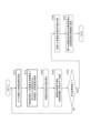
- FIG. 2 is a block diagram showing the configuration of the fish finding device according to the embodiment.
- FIG. 3 is a flowchart illustrating basic processing for optimizing the transmission conditions of the ultrasonic transducer according to the embodiment.
- FIG. 4 is a flowchart showing processing for optimizing the transmission frequency according to the embodiment.
- FIG. 5(a) is a graph showing an example of the frequency-impedance characteristic of the ultrasonic transducer according to the embodiment.
- FIG. 5(b) is a graph showing an example of frequency-phase characteristics of the ultrasonic transducer according to the embodiment.
- FIG. 5(c) is a graph showing an example of the frequency-equivalent parallel resistance characteristic of the ultrasonic transducer according to the embodiment.
- FIG. 6 is a flowchart illustrating processing for optimizing transmission voltage according to the embodiment.
- FIG. 7 is a flowchart illustrating processing for optimizing transmission voltage according to modification example 1.
- FIG. 8 is a diagram schematically showing a test period added to one sequence in order to perform transmission frequency optimization processing according to modification example 2.
- FIG. 9 is a flowchart illustrating processing for optimizing the transmission frequency according to modification example 2.
- FIG. 10 is a diagram schematically showing a test period added to one sequence in order to perform transmission voltage optimization processing according to modification example 2.
- FIG. 11 is a flowchart illustrating processing for optimizing transmission voltage according to modification example 2.
- a fish detection device is shown as an example of an underwater detection device.
- FIG. 1 is a diagram showing how the fish finding device is used.
- a transducer 2 is installed on the bottom of a ship 1, and a transmission beam 3 (ultrasonic wave) is transmitted from the transducer 2 into the water.
- the transmission beam 3 has a conical shape with a small apex angle, and is transmitted in a pulsed manner in a vertically downward direction.
- the transmitted beam 3 is reflected by the water bottom 4 and the school of fish 5, and the reflected wave (echo) is received by the transducer 2. Echo data in which the signal strength (echo strength) of the received signal is distributed in the detection range in the water depth direction is generated by the received signal of the reflected wave based on one transmission of the transmission beam 3.
- an echo image showing the distribution of signal intensity (echo intensity) in the water depth direction is generated.
- the echo image includes the intensity distribution of echoes from each target.
- the generated underwater echo image is displayed on a display unit installed in the wheelhouse of the ship 1 or the like. This allows the user to confirm underwater targets (water bottom 4, fish school 5, etc.).
- FIG. 2 is a block diagram showing the configuration of the fish finding device 100.
- the fish finding device 100 includes a control circuit 101, a memory 102, a transmitting circuit 103, a receiving circuit 104, a switching circuit 105, an input section 106, a display section 107, and a transmitting voltage measurement device. It includes a circuit 108, a transmission current measurement circuit 109, and the transducer 2 shown in FIG.
- the control circuit 101, memory 102, transmission circuit 103, reception circuit 104, switching circuit 105, input section 106, display section 107, transmission voltage measurement circuit 108, and transmission current measurement circuit 109 are installed in the wheelhouse of the ship 1, etc. .
- the configuration other than the transducer 2 may be integrated into one housing, or some components such as the display section 107 may be separated.
- the switching circuit 105 is communicably connected to the transducer 2 via a signal cable.
- the transducer 2 includes a wave transmitting element used for transmitting ultrasonic waves and a wave receiving element used for receiving ultrasonic waves.
- the wave transmitting element and the wave receiving element of the transducer 2 are constituted by one ultrasonic transducer 21.
- the transmission circuit 103 generates a transmission signal for driving the ultrasonic transducer 21 from the control signal input from the control circuit 101, and transmits the generated transmission signal to the ultrasonic wave of the transducer 2 via the switching circuit 105. Output to the vibrator 21.
- control circuit 101 outputs a frequency control signal that has a rectangular amplitude at a predetermined control frequency and a voltage control signal that defines a control voltage to the transmission circuit 103 as the above-mentioned control signals.
- the transmission circuit 103 generates a transmission signal having a frequency similar to the control frequency of the input frequency control signal and a transmission voltage similar to the control voltage of the input voltage control signal.
- the control circuit 101 outputs the generated control signal to the ultrasound transducer 21 via the switching circuit 105.
- the ultrasonic transducer 21 transmits ultrasonic waves (transmission beam 3) into the water based on the input transmission signal. Further, the ultrasonic transducer 21 receives reflected waves of the transmitted ultrasonic waves, and outputs a received signal having a magnitude corresponding to the intensity of the reflected waves to the receiving circuit 104 via the switching circuit 105. The switching circuit 105 switches transmission and reception of signals to and from the ultrasonic transducer 21 .
- the receiving circuit 104 includes a filter that extracts the frequency component of the transmitted wave from the received signal from the ultrasonic transducer 21, and an amplification circuit that amplifies the received signal.
- the receiving circuit 104 generates echo data indicating echo intensity for each depth based on the received signal of the frequency components extracted by the filter. Specifically, the receiving circuit 104 generates, as echo data, data that associates the elapsed time from the timing of transmitting the ultrasound (transmission beam 3) with the intensity of the reflected wave, and uses the generated echo data as echo data. It is output to the control circuit 101.
- the elapsed time from the timing of transmitting the ultrasound corresponds to the depth.
- the intensity of the reflected wave attenuates as the depth increases. Therefore, the receiving circuit 104 corrects the intensity of the reflected wave that attenuates depending on the elapsed time, and outputs the echo data with the intensity corrected to the control circuit 101.
- the control circuit 101 is composed of an arithmetic processing circuit such as a CPU or an integrated circuit such as an FPGA.
- the memory 102 is composed of ROM, RAM, hard disk, etc.
- the memory 102 stores various programs. These programs include a program that causes the control circuit 101 (computer) to execute a function of processing echo data to generate an image and a function of optimizing the transmission conditions of the ultrasound transducer 21.
- the memory 102 is used as a work area during processing by the control circuit 101.
- the control circuit 101 controls each section according to a program stored in the memory 102. The process of optimizing the transmission conditions of the ultrasonic transducer 21 will be explained later with reference to FIGS. 3 to 6.
- the input unit 106 is comprised of input means such as a mouse and a keyboard, and accepts input from the user.
- the input unit 106 may be a touch panel integrated into the display unit 107.
- the display unit 107 is configured with a display device such as a CRT monitor or a liquid crystal panel, and displays images generated by the control circuit 101. As described above, the display unit 107 displays an echo image generated based on echo data.
- the control circuit 101 acquires echo data in which depth and echo intensity are associated with each other at each transmission timing of the ultrasound (transmission beam 3).
- the control circuit 101 generates an echo image based on one frame of continuously acquired echo data, and causes the display unit 107 to display the echo image.
- An echo image is sometimes called an echo diagram.
- An echo image is an image in which echo intensity is distributed in a coordinate area with depth and time as two axes.
- each pixel is colored or shaded in gradation according to the signal strength of the reflected wave.
- a user such as a fisherman can understand the position and range of a school of fish underwater by referring to the echo image displayed on the display unit 107.
- the transmission voltage measurement circuit 108 measures the transmission voltage supplied from the transmission circuit 103 to the ultrasound transducer 21.
- Transmission current measurement circuit 109 measures the transmission current supplied from transmission circuit 103 to ultrasound transducer 21 .
- the configurations of the transmission voltage measurement circuit 108 and the transmission current measurement circuit 109 are similar to the configurations of the transmission voltage measurement circuit and the transmission current measurement circuit used for measuring the transmission voltage and transmission current of a power supply circuit or the like.
- the transmission voltage measurement circuit 108 and the transmission current measurement circuit 109 adjust the parameters (resistance value, etc.) of each element to match the magnitude of the transmission voltage and transmission current that can be expected to be supplied to the ultrasonic transducer 21. has been adjusted.
- a process of optimizing the transmission conditions of the ultrasonic transducer 21 is performed using the transmission voltage and transmission current measured by the transmission voltage measurement circuit 108 and the transmission current measurement circuit 109.
- FIG. 3 is a flowchart showing basic processing for optimizing the transmission conditions of the ultrasonic transducer 21.
- the process shown in FIG. 3 is executed, for example, immediately after the fish finding device 100 is started, when the operation is interrupted, or by an arbitrary instruction from the user.
- this process is executed in response to an instruction from the user, generation of echo data and updating of the echo image are interrupted during this process.
- control circuit 101 controls the transmission circuit 10 while changing the control frequency and control voltage.
- a control signal is output to 3.
- the control circuit 101 causes the transmission circuit 103 to output a transmission signal while changing the transmission frequency and transmission voltage (S11).
- measured values of the transmission voltage and transmission current are output from the transmission voltage measurement circuit 108 and the transmission current measurement circuit 109 to the control circuit 101.
- the control circuit 101 acquires these measured values for each combination of transmission frequency (control frequency) and transmission voltage (control voltage) (S12). Then, the control circuit 101 optimizes the transmission conditions of the ultrasonic transducer 21 based on the acquired measured values of the transmission voltage and transmission current (S13).
- optimization of transmission conditions includes optimization of transmission frequency and transmission voltage.
- specific processing for optimizing the transmission frequency and optimizing the transmission voltage will be described.
- the range of frequencies that can be used for transmission (hereinafter referred to as "nominal band"), the initial value of the transmission voltage, the upper limit of the transmission current, and the upper limit of the transmission power are value is used.
- the initial value of the transmission voltage for example, the minimum value of the transmission voltage range (appropriate operating range) in which the transducer 2 (ultrasonic transducer 21) can properly operate in transmitting waves may be used.
- the initial value of the transmission voltage may be any other voltage value within the proper operating range.
- the upper limit value of the transmitting current is the rated value of the transmitting current defined by the hardware constraints of the transmitting system including the transmitting circuit 103, and the upper limit value of the transmitting power is the rated power of the ultrasonic transducer 21.
- the upper limit value of the transmission current may be set slightly lower than the above-mentioned rated value, and the upper limit value of the transmission power may be set slightly lower than the above-mentioned rated value.
- These values are input by a service person via the input unit 106, for example, when installing the fish finding device 100 (including when replacing components other than the transducer 2).
- the service person for example, refers to a correspondence table in which these values are mapped to the model of the transducer 2 and the model of the fish finder 100, and determines the target transducer 2 and fish finder 100. Enter the value corresponding to 100.
- the upper limit value of the transmission current (rated current of the transmission system) may be stored in the memory 102 in advance.
- FIG. 4 is a flowchart showing the process for optimizing the transmission frequency.
- the control circuit 101 sets the target frequency to a predetermined frequency within the nominal band (S101).
- the control circuit 101 outputs a control signal according to the set target frequency and the initial value of the transmission voltage to the transmission circuit 103, and transmits the measured value of the transmission voltage and the measured value of the transmission current to the transmission voltage measurement circuit 108 and the transmission current measurement circuit 108. It is acquired from the circuit 109 (S102).
- the control circuit 101 calculates the equivalent parallel resistance from the acquired transmission voltage measurement value and transmission current measurement value (S103).
- step S103 the control circuit 101 calculates the impedance Z of the ultrasonic transducer 21 from the measured value Vm of the transmission voltage and the measured value Im of the transmission current using the following equation (1).
- control circuit 101 obtains the phase ⁇ between the control voltage and the transmission voltage, and calculates the value of the equivalent parallel resistance Rp from the obtained phase ⁇ and the impedance Z using the following formula.
- the control circuit 101 stores the calculated value of the equivalent parallel resistance Rp in the memory 102 in association with the target frequency set in step S101 (S104).
- the control circuit 101 determines whether the processing of steps S101 to S104 has been completed for all frequencies set at predetermined frequency intervals within the nominal band (S105). If the determination in step S105 is NO, the control circuit 101 sets the next frequency within the nominal band as the target frequency in step S101, and similarly executes the processes in steps S102 to S104. The control circuit 101 repeatedly executes this process until the determination in step S105 becomes YES.
- the control circuit 101 acquires the equivalent parallel resistance of each target frequency stored in the memory 102. The values of are compared with each other (S106). Then, the control circuit 101 sets the target frequency at which the minimum equivalent parallel resistance value among these equivalent parallel resistance values is obtained as the optimum value of the transmission frequency (S107). Thereby, the control circuit 101 ends the process of FIG.
- all equivalent parallel resistance values for all target frequencies are stored in the memory 102, and then all stored equivalent parallel resistance values are compared to determine the minimum equivalent parallel resistance value.
- the method for extracting the value of the minimum equivalent parallel resistance is not limited to this.
- the control circuit 101 each time the control circuit 101 calculates the value of the equivalent parallel resistance, the control circuit 101 compares the value of the equivalent parallel resistance stored in the memory 102 as the minimum so far with the calculated value of the equivalent parallel resistance, If the calculated value of the equivalent parallel resistance is smaller, the value of the calculated equivalent parallel resistance is stored in the memory 102 instead of the value of the equivalent parallel resistance that was the minimum until then.
- the value of the equivalent parallel resistance and its target frequency may be obtained.
- FIGS. 5(a) to 5(c) are graphs showing examples of the impedance Z, phase ⁇ , and equivalent parallel resistance Rp of each target frequency calculated in step S103 of FIG. 4, respectively.
- FIG. 5(a) shows an example of the frequency-impedance characteristic of the ultrasonic transducer 21
- FIG. 5(b) shows an example of the frequency-phase characteristic of the ultrasonic transducer 21
- 5(c) shows an example of the frequency-equivalent parallel resistance characteristic of this ultrasonic transducer 21.
- the nominal band is set to about 150 to 240 kHz.
- the impedance characteristics in FIG. 5(a) are calculated by applying the measured value Vm of the transmitted voltage and the measured value Im of the transmitted current obtained at each target frequency to the above formula (1). be.
- the equivalent parallel resistance characteristic in FIG. 5(c) is calculated by using the above equation (2) by calculating the impedance Z value of each target frequency in FIG. 5(a) and the phase ⁇ of each target frequency in FIG. 5(b). It was calculated by applying it to
- the value of the equivalent parallel resistance Rp is minimum near 160 kHz. Therefore, in this example, 160 kHz is set as the optimal value for the transmission frequency.
- the transmission power of the ultrasonic transducer 21 can be increased most efficiently. Therefore, by setting the frequency at which the equivalent parallel resistance Rp is minimum as the optimum value of the transmission frequency through the process shown in FIG. 4, ultrasonic waves can be transmitted most efficiently.
- FIG. 6 is a flowchart showing the process for optimizing the transmission voltage.
- the control circuit 101 sets the transmission frequency to the frequency optimized by the process of FIG. 4 (S201), and further sets the transmission voltage to the initial value (S202).
- the initial value is the minimum value of the proper operating range of the transmission voltage, as described above.
- the control circuit 101 outputs a control signal according to the set transmission frequency and transmission voltage to the transmission circuit 103, causes the transmission circuit 103 to output a transmission signal according to the transmission frequency and transmission voltage, and adjusts the transmission voltage and transmission current.
- the measured value of is acquired from the transmission voltage measurement circuit 108 and the transmission current measurement circuit 109 (S203).
- the control circuit 101 determines whether the acquired transmission current exceeds the upper limit value (S204). As described above, this upper limit value is the rated value of the transmission current defined by the hardware constraints of the transmission system including the transmission circuit 103. If the transmission current does not exceed the upper limit (S204: NO), the control circuit 101 determines whether the transmission power calculated from the acquired transmission voltage and transmission current exceeds the upper limit (S205). This upper limit value is the rated power of the ultrasonic transducer 21, as described above.
- the control circuit 101 determines whether the transmission voltage has converged to the maximum allowable value (S206). That is, after the transmission voltage is reduced by a predetermined voltage in step S208, the control circuit 101 determines whether the determination in step S205 is NO and the process moves to step S206.
- step S206 If the determination in step S206 is NO, that is, if the transmission voltage has not yet been reduced in step S208, the control circuit 101 increases the current transmission voltage by a predetermined voltage by increasing the current control voltage by a predetermined voltage. It is increased (S209), and the process returns to step S203.
- the predetermined voltage is set, for example, to a voltage with a minimum width that allows the transmission voltage to be increased or decreased. That is, the predetermined voltage is set to a voltage corresponding to one step when increasing/decreasing the transmission voltage in steps. Note that the transmission frequency is maintained at the optimum value set in step S201.
- the control circuit 101 increases the transmission voltage by a predetermined voltage until the determination in either step S204 or S205 becomes YES, and repeatedly executes the processing in steps S203 to S206 for each transmission voltage. . After that, if the determination in either step S204 or S205 is YES, the control circuit 101 reduces the control voltage by a predetermined voltage, thereby reducing the transmission voltage by a predetermined voltage (S208), and returns the process to step S203. .
- This predetermined voltage is set to be the same as the predetermined voltage in step S209.
- the control circuit 101 executes the processing from step S203 using the reduced transmission voltage.
- the voltage value of the transmission voltage after reduction is the voltage value that was subjected to the processing from step S203 onward, and this voltage value is the voltage value that was used in the processing from step S203 onwards, and the determination in steps S204 and S205 was NO in the processing on the previous day. . Therefore, it is normally assumed that the determinations in steps S204 and S205 will be NO this time as well. However, exceptionally, if either of the determinations in step S204 or S205 is YES, the control circuit 101 reduces the transmission voltage by a predetermined voltage again in step S208, and executes the processing from step S203 onwards. do.
- the control circuit 101 performs the determination in step S206.
- the determination in step S206 is YES.
- the transmission voltage at this time becomes the maximum voltage value within a range in which both the transmission current and the transmission power do not exceed their respective upper limits.
- step S206 If the determination in step S206 is YES, the control circuit 101 sets the transmission voltage (control voltage) at this time to the optimum value (S207), and ends the process. Thereafter, the control circuit 101 causes the transmitting circuit 103 to output a transmitting signal to which the optimum value of the transmitting frequency set by the process of FIG. 4 and the optimum value of the transmitting voltage set by the process of FIG. Transmits ultrasonic waves at the same time. Thereby, ultrasonic waves can be transmitted efficiently and appropriately, and echo images can be displayed smoothly and appropriately.
- the predetermined voltage defined in steps S208 and S209 does not necessarily have to be the minimum width voltage that allows the transmission voltage to be increased or decreased.
- the predetermined voltage in step S209 may change depending on the number of times the transmission voltage is increased. In other words, until the number of times the transmission voltage is increased reaches a predetermined number (for example, several times), the voltage for multiple steps when increasing and decreasing the transmission voltage in steps is set to the predetermined voltage, and the number of times the transmission voltage is increased is set to the predetermined voltage. After reaching a predetermined number of times (for example, several times), the voltage for one step when increasing/decreasing the transmission voltage in steps may be set to the predetermined voltage.
- predetermined voltages in steps S209 and S208 do not necessarily have to be the same.
- the predetermined voltage in step S208 may be greater than the predetermined voltage in step S209.
- the fish finding device 100 (underwater finding device) includes a transmitting circuit 103 that supplies a transmitting voltage and a transmitting current to the ultrasonic transducer 21, and a transmitting circuit 103 that supplies a transmitting voltage and a transmitting current to the ultrasonic transducer 21. It includes a transmission voltage measurement circuit 108 for measuring, a transmission current measurement circuit 109 for measuring the transmission current supplied to the ultrasonic transducer 21, and a control circuit 101. As shown in FIG. 3, the control circuit 101 optimizes the transmission conditions of the ultrasonic transducer 21 based on the transmission voltage and transmission current measured by the transmission voltage measurement circuit 108 and the transmission current measurement circuit 109, respectively. Execute (S13).
- the fish finder 100 can measure the transmitting voltage and transmitting current of the ultrasonic transducer 21 included in the transducer 2 using the transmitting voltage measuring circuit 108 and the transmitting current measuring circuit 109. , From these measurement results, the transmission conditions of the ultrasonic transducer 21 can be optimized. In addition, even if there are individual differences in the transducer 2, the actual transmission voltage and transmission current of the ultrasonic transducer 21 included in the transducer 2 can be measured, so the optimum transmission for the ultrasonic transducer 21 can be achieved. Conditions can be set in the fish finding device 100 (underwater finding device).
- the transmission voltage and current of the ultrasonic transducer 21 can be measured in that environment, so the optimal transmission conditions can be determined according to the underwater environment for fish detection. It can be set in the device 100 (underwater detection device). Therefore, the transmission conditions of the ultrasonic transducer 21 included in the transducer 2 can be easily and accurately optimized.
- the control circuit 101 controls the transmission voltage and transmission voltage measured by the transmission voltage measurement circuit 108 and the transmission current measurement circuit 109 under actual usage conditions (the upper limit values in steps S204 and S205), respectively.
- the transmission conditions of the ultrasonic transducer 21 are optimized under the conditions of actual use, so that the transmission conditions optimized for the actual use of the fish finding device 100 (underwater detection device) Waves can be properly transmitted from the ultrasonic transducer 21.
- the control circuit 101 optimizes the transmission voltage as optimization of the transmission conditions.
- the control circuit 101 increases the transmission voltage within a range where the transmission power and transmission current calculated from the transmission voltage and transmission current do not exceed their respective upper limit values (S204: NO, S205: NO). By doing so (S209), the transmission voltage is optimized.
- the transmission voltage as high as possible can be set as the optimum value of the transmission voltage within a range where the transmission power and the transmission current do not exceed their respective upper limit values.
- control circuit 101 transmits ultrasonic waves under the condition that the transmission power and transmission current measured by the current transmission voltage do not reach their respective upper limit values (S204: NO, S205: NO).
- Control (S209) for increasing the transmission voltage applied to the vibrator 21 by a predetermined voltage from the current transmission voltage is repeatedly executed. Thereby, as the transmission voltage increases, the transmission power and the transmission current can be gradually brought closer to their respective upper limit values, and the transmission voltage can be smoothly set to a voltage value as high as possible.
- control circuit 101 adjusts the transmission voltage. Control is performed to reduce the voltage by a predetermined value and return it to the transmission voltage immediately before exceeding the upper limit value (S208).
- control circuit 101 performs control to reduce the transmission voltage by a predetermined voltage and return it to the transmission voltage immediately before exceeding the upper limit value (S208), and if the conditions (S204, S205) are satisfied ( S206: YES), the optimization of the transmission voltage is completed (S207).
- the transmission voltage can be set to a voltage value as high as possible within a range where the transmission power and transmission current do not exceed their respective upper limits.
- the predetermined voltage in step S209 may be set to the minimum width voltage that allows the transmission voltage to be increased or decreased. This prevents the transmission power and transmission current from greatly exceeding their respective upper limit values when the transmission voltage is increased by a predetermined voltage value from a state where the transmission power and transmission voltage are slightly lower than their respective upper limit values. It can be suppressed. Therefore, it is possible to prevent problems such as damage to the ultrasonic transducer 21 and the transmission system from occurring due to excessive transmission power and transmission current being applied to the ultrasonic transducer 21 and the transmission system.
- the control circuit 101 optimizes the transmission frequency as optimization of the transmission conditions.
- the control circuit 101 acquires the transmission voltage and transmission current from the transmission voltage measurement circuit 108 and the transmission current measurement circuit 109 while changing the frequency of the transmission signal (S101, S102), and acquires the transmission voltage and transmission current for each frequency.
- the equivalent parallel resistance is calculated from the transmission current (S103), and the frequency at which the value of the calculated equivalent parallel resistance is the minimum is acquired as the optimum value of the transmission frequency (S107).
- FIG. 7 is a flowchart illustrating processing for optimizing transmission voltage according to Modification Example 1.
- step S204 the processing flow after step S204 is shown for convenience.
- the processing in steps S201 to S203 is similar to the corresponding processing in FIG.
- step S210 is added to the flowchart of FIG.
- the processing of steps other than step S210 is the same as the corresponding steps of FIG.
- control circuit 101 further controls the current transmission frequency at a plurality of transmission frequencies that can be used for ultrasound transmission, that is, at all frequencies in the above-mentioned nominal band. It is determined whether the transmission power and transmission current obtained from the voltage do not exceed their respective upper limit values (S210).
- step S210 the control circuit 101 causes the transmission circuit 103 to output a transmission signal at the current transmission voltage while changing the transmission frequency at predetermined frequency intervals within the nominal band, and transmits the transmission voltage and transmission current at each frequency. Obtained from voltage measurement circuit 108 and transmission current measurement circuit 109. The control circuit 101 calculates transmission power for each frequency with respect to the acquired transmission voltage and transmission current of each frequency. Then, the control circuit 101 performs the same determination as in steps S204 and S205 for the transmission current and transmission power of each frequency.
- step S210 If either the transmission current or the transmission power exceeds their respective upper limit values (the same upper limit values as in steps S204 and S205) at any frequency, the control circuit 101 makes the determination in step S210 NO and changes the current The transmission voltage is reduced by a predetermined voltage (S208). On the other hand, if neither the transmission current nor the transmission power exceeds their respective upper limit values (the upper limit values similar to steps S204 and S205) at any frequency, the determination in step S210 is set as YES, and the process returns to step S206. Proceed to. The processing after step S206 is similar to the processing shown in FIG. 6 in the above embodiment.
- the optimum value of the transmission voltage set in step S207 is determined by changing the transmission frequency from the optimum value set by the process of FIG. 4 to another frequency within the nominal band.
- the transmission current and transmission power are set to voltage values that do not exceed their respective upper limits. Therefore, even if the transmission frequency of the ultrasonic transducer 21 is switched from the optimum value to another transmission frequency due to interference with ultrasonic waves transmitted from another ship, the optimum value obtained in step S207
- the transmission voltage By setting the transmission voltage to , it is possible to appropriately transmit ultrasonic waves at the transmission voltage set (optimized) to a voltage value as high as possible at other transmission frequencies.
- step S210 of FIG. 7 it is determined whether the conditions of steps S204 and S205 are satisfied for all frequencies within the nominal band, but the frequencies to be determined are not limited to this. For example, several (plural) frequencies preset within the nominal band may be determined in step S210, or in the process of FIG. A plurality of frequencies may be subjected to the determination in step S210.
- modification example 1 in the process for optimizing the transmission voltage, steps are taken in advance so that the transmission frequency can be changed immediately even if interference with the transmission frequency with another ship occurs. S210 has been added.
- the present invention is not limited to this, and after actual operation is performed by setting the optimum values obtained through the processing of FIGS. 4 and 6 as the transmission frequency and transmission voltage of the transmission signal, interference of the transmission frequency with other ships In response to this occurrence, the process shown in FIG. 6 may be performed using a transmission frequency that does not interfere with other ships, and the optimum value of the transmission voltage may be reset.
- FIG. 8 is a diagram schematically showing a test period added to one sequence to perform transmission frequency optimization processing.
- one sequence includes a transmission period for transmitting ultrasound waves, a reception period for receiving reflected waves of ultrasound waves, and a transmission signal (hereinafter referred to as A test period is set for applying a test signal (referred to as a "test signal").
- ultrasonic waves are transmitted using a transmission signal whose transmission frequency and transmission voltage are the optimum value f0 and the optimum value V0, respectively.
- the optimal values f0 and V0 at the time of startup of the fish finding device 100 can be obtained, for example, by performing the processes shown in FIGS. 4 and 6 in response to startup.
- the optimum values f0 and V0 at the time of startup may be default values, or may be the optimum values f0 and V0 obtained at the end of the previous operation of the fish finding device 100.
- the control circuit 101 transmits and receives the transmission signals with the optimum values f0 and V0, and performs transmission frequency optimization processing ( Figure 9) is executed.
- control circuit 101 causes transmission circuit 103 to output a test signal with frequency f1 and voltage value Vs during the test period of sequence S1.
- Frequency f1 is, for example, the minimum frequency in the nominal band.
- the voltage value Vs is an initial value set in step S102 of FIG. 4.
- the control circuit 101 causes the transmitting circuit 103 to output a test signal having a frequency f2 and a voltage value Vs.
- Frequency f2 is, for example, the second frequency from the bottom in the nominal band.
- control circuit 101 causes the transmission circuit 103 to output a test signal in which only the frequency is changed within the nominal band during the test period of each sequence.
- control circuit 101 causes the transmission circuit 103 to output the test signal of the last frequency fn within the nominal band, thereby ending the output of the test signal for performing the transmission frequency optimization process.
- FIG. 9 is a flowchart illustrating processing for optimizing the transmission frequency according to Modification Example 2.
- steps S101 and S102 in the flowchart of FIG. 4 are replaced with steps S111 and S112. Processing in other steps is similar to the corresponding steps in FIG.
- step S111 the control circuit 101 sets one target frequency within the nominal band during the test period in FIG.
- step S112 the control circuit 101 causes the transmission circuit 103 to output a test signal of the transmission voltage at the target frequency and the initial voltage value, and causes the transmission voltage measurement circuit 108 and the transmission current measurement circuit 109 to output a test signal of the transmission voltage at the target frequency and the initial voltage value.
- a transmission voltage and a transmission current are respectively acquired from (S102).
- steps S103 and S104 the control circuit 101 calculates and stores the value of the equivalent parallel resistance from the acquired transmission voltage and transmission current.
- the control circuit 101 repeatedly executes the processes of steps S111 to S104 for each sequence while changing the target frequency set during the test period within the nominal band. In this way, when the calculation and storage of the equivalent parallel resistance values for all frequencies within the nominal band are completed (S105: YES), the control circuit 101 selects the target frequency corresponding to the minimum equivalent parallel resistance value from the transmission frequency. is set to the optimum value (S106, S107), and the process of FIG. 9 is ended.
- FIG. 10 is a diagram schematically showing a test period added to one sequence to perform transmission voltage optimization processing.
- Each sequence in FIG. 10 is performed following sequence Sn in FIG. 8.
- the voltage value Vs of the test signal is not changed in each test period, and the frequency of the test signal is changed from f1 to fn, but in each sequence in FIG. 10, in each test period, The voltage value of the test signal is changed to V1 to Vm without changing the frequency f0 of the test signal.
- the frequency f0 is the optimum value of the transmission frequency obtained by the process of FIG.
- the voltage value V1 is the initial value of the transmission voltage in step S202 of FIG.
- FIG. 11 is a flowchart illustrating processing for optimizing transmission voltage according to Modification Example 2.
- steps S201, S202, S208, and S209 in the flowchart of FIG. 6 are replaced with steps S211, S212, S213, and S214, respectively. Processing in other steps is similar to the corresponding steps in FIG.
- step S211 the control circuit 101 sets the transmission frequency of the test signal during the test period of each sequence to the optimal value obtained in the process of FIG.
- step S212 the control circuit 101 sets the transmission voltage of the test signal during the test period of the first sequence to an initial value. After that, during the test period of the first sequence, the control circuit 101 causes the transmission circuit 103 to output the test signal of the transmission frequency and transmission voltage set in steps S211 and S212, and performs the processing of steps S203 to S206.
- control circuit 101 increases the transmission voltage of the test signal in the next sequence by a predetermined voltage (S214). On the other hand, if the determination in either step S204 or S205 is YES, the control circuit 101 reduces the transmission voltage of the test signal in the next sequence by a predetermined voltage (S213).
- the control circuit 101 repeatedly executes the processes of steps S203 to S206, S213, and S214 until the determination in step S206 becomes YES, and changes the transmission voltage of the test signal set in the test period of each sequence. If the determination in step S206 is YES, the voltage value of the transmission voltage of the test signal set at that time is set to the optimum value of the transmission voltage (S207), and the process of FIG. 11 is ended.
- the control circuit 101 uses the optimum values of the transmission frequency and transmission voltage obtained by the processes of FIGS. 9 and 11 as the transmission frequency and transmission voltage in the subsequent actual operation of fish detection. Set. Then, the control circuit 101 again executes the process of FIG. 9 to obtain the optimum value of the transmission frequency, and further executes the process of FIG. 11 to obtain the optimum value of the transmission voltage. The control circuit 101 resets each newly acquired optimal value to the transmission frequency and transmission voltage in subsequent actual operation. After that, the control circuit 101 repeatedly executes the process of resetting the transmission frequency and transmission voltage. In this way, the control circuit 101 resets each of the optimal values obtained at any time to the transmission frequency and transmission voltage in actual operation, and performs wave transmission and reception for detecting schools of fish.
- a transmission signal (test signal) for optimizing transmission conditions is also transmitted. It is output from the transmitting circuit 103. That is, the control circuit 101 causes the transmission circuit 103 to output a transmission signal (test signal) for optimizing transmission conditions at a timing different from the transmission of ultrasonic waves for detecting a school of fish.
- a transmission signal for optimization can be output in parallel to the transmission circuit 103, and the transmission voltage and transmission current can be measured by the transmission voltage measurement circuit 108 and the transmission current measurement circuit 109. Therefore, the transmission conditions of the ultrasonic transducer 21 can be optimized in real time in parallel with the actual fish detection operation.
- the reflected waves of the ultrasonic waves transmitted by the test signals of each sequence are reflected during the receiving period together with the reflected waves of the detection ultrasonic waves transmitted during the transmitting period. can be received.
- most of the frequencies of the test signals in each sequence are different from the transmission frequency during the wave transmission period, most of the received signals based on the reflected waves of the test signals are removed by the filter of the receiving circuit 104.
- the output period of the test signal that is, the test period may be significantly short. . Therefore, even if the received signal based on the test signal cannot be removed by a filter from the received signal based on the transmitted signal during the wave transmission period, the influence of the test signal on the echo image will be negligible. It is something. Therefore, even if a test signal is output including a test period in one sequence as shown in FIG. 8, the echo image is hardly affected by the test signal.
- the transmission conditions of the ultrasonic transducer 21 can be properly optimized in real time while the actual operation of fish detection can be performed appropriately.
- step S210 when the process in FIG. 11 is modified in the same manner as in Modification Example 1 (FIG. 7), in step S210, the current transmission voltage is changed while the transmission frequency is changed within the nominal band during the test period of each sequence. Accordingly, processing similar to steps S204 and S205 may be executed. As a result, the same processing as in FIG. 7 is realized.
- the frequencies to be processed in step S210 may not be all frequencies within the nominal band, but may be several (plural) frequencies included in the nominal band. Good too.
- optimization of the transmission frequency and optimization of the transmission voltage were performed as optimization of the transmission conditions, but optimization of the transmission conditions is not limited to this. .
- only one of the transmission frequency optimization process and the transmission voltage optimization process may be performed, and a default value or the like may be used for the other.
- a frequency suitable for the transducer 2 may be set as the transmission frequency.
- the transmission frequency optimization process and the transmission voltage optimization process do not necessarily have to be executed as a pair. For example, after each optimization process for the transmission frequency and the transmission voltage is performed, only the optimization process for the transmission voltage may be performed for a certain period of time.
- test periods are set for all sequences, but test periods may be set for each predetermined number of sequences, and the processes of FIGS. 9 and 11 may be executed. Further, the processes shown in FIGS. 9 and 11 do not have to be performed in parallel during the entire actual operation period of the fish finding device 100. For example, the processes shown in FIGS. Processing No. 11 may be performed in parallel with the actual operation of the fish finding device 100.
- test period is set at the beginning of each sequence, but the position of the test period in each sequence is not limited to this.
- a test period may be set following the wave reception period.
- the present invention was applied to the fish finding device 100 mounted on the boat 1, but the present invention is not limited to this.
- the present invention may be applied to a fish finding device installed in a fixed net, or the present invention may be applied to an underwater detection device other than a fish finding device, such as a scanning sonar.
- the transducer does not necessarily have a configuration in which one ultrasonic transducer is used for both transmitting and receiving waves, and there is an ultrasonic transducer for transmitting waves and an ultrasonic transducer for receiving waves.
- the configuration may include the following separately.
- the present invention also provides predetermined functions to the ultrasonic transmitting/receiving device, the ultrasonic transmitting/receiving method, and the control circuit of the ultrasonic transmitting/receiving device. It can also be extracted as a program to be executed.
- the ultrasonic transmitting/receiving device according to this aspect has the same configuration as the transmitting circuit, the transmitting voltage measuring circuit, the transmitting current measuring circuit, and the control circuit recited in the claims, and the ultrasonic transmitting/receiving method and program according to this aspect. may include steps and functions similar to the methods and programs recited in the claims.
- Ultrasonic transducer 100 Fish finder (underwater finder) 101 Control circuit 108 Transmission voltage measurement circuit 109 Transmission current measurement circuit
Landscapes
- Engineering & Computer Science (AREA)
- Physics & Mathematics (AREA)
- Radar, Positioning & Navigation (AREA)
- Remote Sensing (AREA)
- Computer Networks & Wireless Communication (AREA)
- General Physics & Mathematics (AREA)
- Acoustics & Sound (AREA)
- Signal Processing (AREA)
- Measurement Of Velocity Or Position Using Acoustic Or Ultrasonic Waves (AREA)
Abstract
【課題】送受波器に含まれる超音波振動子の送信条件を簡易且つ精度良く最適化することが可能な水中探知装置、送信条件の最適化方法およびプログラムを提供する。 【解決手段】魚群探知装置100(水中探知装置)は、送信電圧および送信電流を超音波振動子21に供給する送信回路103と、超音波振動子21に供給される送信電圧を測定する送信電圧測定回路108と、超音波振動子21に供給される送信電流を測定する送信電流測定回路109と、送信電圧測定回路108で測定された送信電圧および送信電流測定回路109で測定された送信電流に基づいて、超音波振動子21の送信条件の最適化を行う制御回路101と、を備える。
Description
本発明は、水中の状態を探知する水中探知装置、および、水中に対して超音波を送波するための超音波振動子の送信条件を自動で最適化する送信条件の最適化方法に関する。
従来、水中の状態を探知する水中探知装置が知られている。水中探知装置では、水中に超音波が送波され、その反射波が受波される。受波された反射波の強度に応じたエコーデータが生成され、生成されたエコーデータに基づいてエコー画像が表示される。
この種の水中探知装置では、既設の送受波器に、新たな制御装置が接続される場合がある。新たな制御装置には、送受波器内に含まれている超音波振動子の送信条件を設定する必要がある。この場合、船底に取り付けられている送受波器内の超音波振動子のインピーダンス特性等を、別途、測定器により調べなければならない。このような作業は、かなり煩雑である。
この問題は、超音波振動子に関する情報を、予め、送受波器に保持させておくことで解消できる。たとえば、超音波振動子の共振周波数、許容入力電力、送受信感度およびインピーダンス等の超音波振動子の特性に関する情報が、送受波器の記憶部に記憶される。この送受波器が新たな制御装置が接続される場合、送受波器の記憶部から上記情報が読み出される。これにより、別途、測定器で測定せずとも、超音波振動子のインピーダンス特性等を取得できる。
このような構成の送受波器が、以下の特許文献1に記載されている。
しかしながら、上記構成では、同じ型式の送受波器には、同じ内容の情報が保持される。このため、送受波器ごとに個体差がある場合、送受波器ごとに最適な送信条件を、水中探知装置に設定できない。また、水中の温度等、水中の環境によって、超音波振動子のインピーダンス特性が変わり得る。上記構成では、このような特性変化に対応することもできない。
かかる課題に鑑み、本発明は、送受波器に含まれる超音波振動子の送信条件を簡易且つ精度良く最適化することが可能な水中探知装置、送信条件の最適化方法、およびプログラムを提供することを目的とする。
本発明の第1の態様は、水中探知装置に関する。本態様に係る水中探知装置は、送信電圧および送信電流を前記超音波振動子に供給する送信回路と、前記送信電圧を測定する送信電圧測定回路と、前記送信電流を測定する送信電流測定回路と、前記送信電圧測定回路および前記送信電流測定回路でそれぞれ測定された送信電圧および送信電流に基づいて、前記超音波振動子の送信条件の最適化を行う制御回路と、を備える。
本態様に係る水中探知装置によれば、送信電圧測定回路および送信電流測定回路によって、送受波器に含まれる超音波振動子の送信電圧および送信電流を測定できるため、これらの測定結果から、超音波振動子の送信条件を最適化できる。また、送受波器に個体差があったとしても、その送受波器に含まれる超音波振動子の実際の送信電圧および送信電流を測定できるため、超音波振動子に最適な送信条件を水中探知装置に設定できる。さらに、水中の温度等、水中の環境が変化しても、その環境下において、超音波振動子の送信電圧および送信電流を測定できるため、水中の環境に応じた最適な送信条件を水中探知装置に設定できる。よって、超音波振動子の送信条件を、簡易且つ精度良く最適化できる。
本態様に係る水中探知装置において、前記制御回路は、前記送信電圧測定回路および前記送信電流測定回路で実使用条件のもとで、それぞれ測定された前記送信電圧および前記送信電流に基づいて、前記超音波振動子の送信条件の最適化を行うよう構成され得る。
この構成によれば、実使用の条件のもとで超音波振動子の送信条件が最適化されるため、水中探知装置の実使用に、最適化された送信条件で適正に超音波振動子から送波を行うことができる。
なお、この構成において、「実使用条件」とは、たとえば、送信回路を含む送信系のハード的な制約から規定される送信電流の定格値や、超音波振動子の定格電力等の実使用において水中探知装置に要求される一定の制約のことである。
本態様に係る水中探知装置において、前記制御回路は、前記送信条件の最適化として、前記送信電圧の最適化を行うよう構成され得る。
この場合、前記制御回路は、前記送信電圧および前記送信電流から算出される送信電力と、前記送信電流とが、それぞれの上限値を超えない範囲内において、前記送信電圧を高めることにより、前記送信電圧の最適化を行うよう構成され得る。
この構成によれば、送信電力および送信電流がそれぞれの上限値を超えない範囲において、なるべく高い送信電圧を送信電圧の最適値に設定できる。
この構成において、前記制御回路は、現在の送信電圧により測定された前記送信電力および前記送信電流がそれぞれの前記上限値に満たないことを条件に、前記送信電圧を、前記現在の送信電圧より所定電圧だけ高める制御を、繰り返し実行するよう構成され得る。
これにより、送信電圧の増加に伴い、送信電力および送信電流を徐々に各々の上限値に近づけることができ、なるべく高い電圧値に送信電圧を円滑に設定できる。
この構成において、前記制御回路は、現在の送信電圧により測定された前記送信電力および前記送信電流がそれぞれの前記上限値を超えた場合には、送信電圧を所定電圧だけ低減させて、当該上限値を超える直前の送信電圧に戻す制御を行うよう構成され得る。
また、前記制御回路は、前記送信電圧を所定電圧だけ低減させて、当該上限値を超える直前の送信電圧に戻す制御を行った後に前記条件が満たされている場合に、前記送信電圧の最適化を完了とするよう構成され得る。
これらの構成によれば、送信電力および送信電流が各々の上限値を超えない範囲において、なるべく高い電圧値に送信電圧を設定できる。
この場合、前記所定電圧は、前記送信電圧を増減可能な最小幅の電圧に設定され得る。
これにより、送信電力および送信電圧が各々の上限値からやや低い値にある状態から送信電圧を所定電圧だけ高めた場合に、送信電力および送信電流が各々の上限値を大きく超えてしまうことを抑制できる。よって、過度の送信電力および送信電流が超音波振動子に印加されて超音波振動子に破損等の不具合が生じることを防ぐことができる。
また、前記制御回路は、前記送信電力および前記送信電流が、前記超音波の送波に用いられる複数の送信周波数において前記それぞれの上限値を超えない範囲で、前記送信電圧を前記所定電圧だけ高める制御を繰り返し実行するよう構成され得る。
この構成によれば、他船から送波された超音波との干渉等により、超音波振動子の送信周波数を他の送信周波数に切り替えた場合であっても、他の送信周波数においてなるべく高い電圧値に設定された(最適化された)送信電圧での超音波の送波を適正に行うことができる。
本態様に係る水中探知装置において、前記制御回路は、前記送信条件の最適化として、送信周波数の最適化を行うよう構成され得る。
この場合、前記制御回路は、前記送信信号の周波数を変化させながら、前記送信電圧測定回路および前記送信電流測定回路から前記送信電圧および前記送信電流を取得し、前記周波数ごとに取得した前記送信電圧および前記送信電流から等価並列抵抗を算出し、算出した前記等価並列抵抗の値が最小となる前記周波数を前記送信周波数の最適値として取得するよう構成され得る。
この構成によれば、超音波振動子に対し最も効率よく送信電力を印加できる送信周波数を、水中探知装置に設定できる。
本態様に係る水中探知装置において、前記制御回路は、探知のために前記超音波の送波および受波を行う1シーケンスにおいて、さらに、前記送信条件の最適化のための送信信号を前記送信回路に出力させるよう構成され得る。
この場合、前記制御回路は、探知のための前記超音波の送波とは異なるタイミングで、前記送信条件の最適化のための送信信号を前記送信回路に出力させるよう構成され得る。
これらの構成によれば、送受波の1シーケンスにおいて、最適化のための送信信号を並行して送信回路に出力でき、送信電圧測定回路および送信電流測定回路により送信電圧および送信電流を測定できる。よって、実際の水中探知動作時にリアルタイムで、送信条件を最適化できる。
本発明の第2の態様は、水中に対して超音波を送波するための超音波振動子の送信条件を自動で最適化する送信条件の最適化方法に関する。この態様に係る送信条件の最適化方法は、実使用時に前記超音波振動子に供給される送信電圧および送信電流を測定し、測定された前記送信電圧および前記送信電流に基づいて、前記超音波振動子の送信条件の最適化を行う。
本態様に係る送信条件の最適化方法によれば、上記第1の態様と同様の効果が奏され得る。
本発明の第3の態様は、送信電圧および送信電流を超音波振動子に供給する送信回路と、前記送信電圧を測定する送信電圧測定回路と、前記送信電流を測定する送信電流測定回
路と、を備える水中探知装置の制御回路に所定の機能を実行させるプログラムに関する。この態様に係るプログラムは、実使用時に前記送信電圧測定回路および前記送信電流測定回路により測定された前記送信電圧および前記送信電流に基づいて、前記超音波振動子の送信条件の最適化を行う機能を実行させる。
路と、を備える水中探知装置の制御回路に所定の機能を実行させるプログラムに関する。この態様に係るプログラムは、実使用時に前記送信電圧測定回路および前記送信電流測定回路により測定された前記送信電圧および前記送信電流に基づいて、前記超音波振動子の送信条件の最適化を行う機能を実行させる。
本態様に係るプログラムによれば、上記第1の態様と同様の効果が奏され得る。
以上のとおり、本発明によれば、送受波器に含まれる超音波振動子の送信条件を簡易且つ精度良く最適化することが可能な水中探知装置、送信条件の最適化方法およびプログラムを提供することができる。
本発明の効果ないし意義は、以下に示す実施形態の説明により更に明らかとなろう。ただし、以下に示す実施形態は、あくまでも、本発明を実施化する際の一つの例示であって、本発明は、以下の実施形態に記載されたものに何ら制限されるものではない。
以下、本発明の実施形態について図面を参照して説明する。なお、以下の実施形態では、水中探知装置の一例として、魚群探知装置が示されている。
図1は、魚群探知装置の使用形態を示す図である。
本実施形態では、船1の船底に送受波器2が設置され、送受波器2から水中に送信ビーム3(超音波)が送波される。送信ビーム3は、頂角が小さい円錐の形状で、鉛直下方向にパルス状に送波される。送信ビーム3は、水底4や魚群5により反射され、反射波(エコー)が、送受波器2で受波される。1回の送信ビーム3の送波に基づく反射波の受信信
号により、水深方向の探知範囲に受信信号の信号強度(エコー強度)が分布するエコーデータが生成される。
号により、水深方向の探知範囲に受信信号の信号強度(エコー強度)が分布するエコーデータが生成される。
所定時間分のエコーデータが蓄積されることにより、水深方向における信号強度(エコー強度)の分布を示すエコー画像が生成される。エコー画像には、各物標からのエコーの強度分布が含まれる。生成された水中のエコー画像は、船1の操舵室等に設置された表示部に表示される。これにより、ユーザは、水中に存在する物標(水底4や魚群5など)を確認できる。
図2は、魚群探知装置100の構成を示すブロック図である。
魚群探知装置100は、送受波器2の他、制御回路101と、メモリ102と、送信回路103と、受信回路104と、切替回路105と、入力部106と、表示部107と、送信電圧測定回路108と、送信電流測定回路109と、図1に示した送受波器2と、を備える。
制御回路101、メモリ102、送信回路103、受信回路104、切替回路105、入力部106、表示部107、送信電圧測定回路108および送信電流測定回路109は、船1の操舵室等に設置される。送受波器2を除く構成が、1つの筐体にユニット化されてもよく、あるいは、表示部107等の一部の構成要素が別体とされてもよい。切替回路105は、信号ケーブルによって、送受波器2に通信可能に接続される。
送受波器2は、超音波の送波に用いられる送波素子と、超音波の受波に用いられる受波素子と、を備える。本実施形態では、送受波器2の送波素子および受波素子が、1つの超音波振動子21により構成されている。
送信回路103は、制御回路101から入力される制御信号から超音波振動子21を駆動するための送信信号を生成し、生成した送信信号を、切替回路105を介して送受波器2の超音波振動子21に出力する。
より詳細には、制御回路101は、所定の制御周波数で矩形に振幅する周波数制御信号と、制御電圧を規定する電圧制御信号とを、上述の制御信号として送信回路103に出力する。送信回路103は、入力された周波数制御信号の制御周波数と同様の周波数を有し、且つ、入力された電圧制御信号の制御電圧と同様の送信電圧を有する送信信号を生成する。制御回路101は、生成した制御信号を、切替回路105を介して超音波振動子21に出力する。
超音波振動子21は、入力された送信信号に基づいて水中に超音波(送信ビーム3)を送波する。また、超音波振動子21は、送波した超音波の反射波を受波し、反射波の強度に応じた大きさの受信信号を、切替回路105を介して受信回路104に出力する。切替回路105は、超音波振動子21に対する信号の送受を切り替える。
受信回路104は、超音波振動子21からの受信信号から送波の周波数成分を抽出するフィルタや、受信信号を増幅するための増幅回路を備える。受信回路104は、フィルタにより抽出した周波数成分の受信信号に基づいて、深度ごとのエコー強度を示すエコーデータを生成する。具体的には、受信回路104は、超音波(送信ビーム3)を送波したタイミングからの経過時間と、反射波の強度とを対応付けたデータをエコーデータとして生成し、生成したエコーデータを制御回路101に出力する。
ここで、超音波を送信したタイミングからの経過時間は、深度に対応する。なお、反射
波の強度は、深度が大きくなるほど減衰する。したがって、受信回路104は、経過時間に応じて減衰する反射波の強度を補正し、強度を補正したエコーデータを制御回路101に出力する。
波の強度は、深度が大きくなるほど減衰する。したがって、受信回路104は、経過時間に応じて減衰する反射波の強度を補正し、強度を補正したエコーデータを制御回路101に出力する。
制御回路101は、CPU等の演算処理回路や、FPGA等の集積回路により構成される。メモリ102は、ROM、RAM、ハードディスク等により構成される。メモリ102には、各種のプログラムが記憶されている。これらプログラムには、エコーデータを処理して画像を生成する機能、および、超音波振動子21の送信条件を最適化する機能を制御回路101(コンピュータ)に実行させるプログラムが含まれている。
また、メモリ102は、制御回路101の処理の際にワーク領域として用いられる。制御回路101は、メモリ102に記憶されたプログラムにより各部を制御する。超音波振動子21の送信条件を最適化する処理は、追って、図3~図6を参照して説明する。
入力部106は、マウスやキーボード等の入力手段により構成され、ユーザからの入力を受け付ける。入力部106は、表示部107に一体化されたタッチパネルであってもよい。表示部107は、CRTモニタや液晶パネル等の表示器により構成され、制御回路101によって生成された画像を表示する。上述のように、表示部107には、エコーデータに基づいて生成されたエコー画像が表示される。
制御回路101は、超音波(送信ビーム3)の送波タイミングごとに、深度とエコー強度とを対応づけたエコーデータを取得する。制御回路101は、連続的に取得した1フレーム分のエコーデータに基づいて、エコー画像を生成し、表示部107に表示させる。エコー画像は、エコーダイアグラムと呼ばれることもある。
エコー画像は、深度と時間とを2軸とする座標領域にエコー強度が分布する画像である。エコー画像では、画素ごとに、反射波の信号強度に応じた階調で色付けまたは濃淡付けが施される。漁師等のユーザは、表示部107に表示されたエコー画像を参照することで、水中における魚群の位置および範囲を把握できる。
送信電圧測定回路108は、送信回路103から超音波振動子21に供給される送信電圧を測定する。送信電流測定回路109は、送信回路103から超音波振動子21に供給される送信電流を測定する。送信電圧測定回路108および送信電流測定回路109の構成は、電源回路等の送信電圧および送信電流の測定に用いられる送信電圧測定回路および送信電流測定回路の構成と同様である。送信電圧測定回路108および送信電流測定回路109は、超音波振動子21に供給されることが想定され得る送信電圧および送信電流の大きさに適合するように、各素子のパラメータ(抵抗値等)が調整されている。
本実施形態では、送信電圧測定回路108および送信電流測定回路109により測定された送信電圧および送信電流によって、超音波振動子21の送信条件を最適化する処理が実行される。
図3は、超音波振動子21の送信条件を最適化するための基本的な処理を示すフローチャートである。
図3の処理は、たとえば、魚群探知装置100の起動直後や、動作中断時、または、ユーザからの任意の指示により実行される。ユーザからの指示によりこの処理が実行される場合、この処理の間、エコーデータの生成およびエコー画像の更新は中断される。
まず、制御回路101は、制御周波数および制御電圧を変化させながら、送信回路10
3に制御信号を出力する。これにより、制御回路101は、送信周波数および送信電圧を変化させながら、送信回路103に送信信号を出力させる(S11)。
3に制御信号を出力する。これにより、制御回路101は、送信周波数および送信電圧を変化させながら、送信回路103に送信信号を出力させる(S11)。
これに応じて、送信電圧測定回路108および送信電流測定回路109から、送信電圧および送信電流の測定値が制御回路101に出力される。制御回路101は、送信周波数(制御周波数)および送信電圧(制御電圧)の組合せごとに、これらの測定値を取得する(S12)。そして、制御回路101は、取得した送信電圧および送信電流の測定値に基づき、超音波振動子21の送信条件の最適化を行う(S13)。
ここで、送信条件の最適化は、送信周波数および送信電圧の最適化を含む。以下、送信周波数の最適化および送信電圧の最適化の具体的処理について説明する。
なお、以下の処理では、送信条件の最適化のために、送信に使用可能な周波数の範囲(以下、「公称帯域」という)、送信電圧の初期値、送信電流の上限値および送信電力の上限値が用いられる。
ここで、送信電圧の初期値は、たとえば、当該送受波器2(超音波振動子21)が送波において適正に動作し得る送信電圧の範囲(適正動作範囲)の最小値が用いられ得る。送信電圧の初期値は、適正動作範囲の他の電圧値であってもよい。また、送信電流の上限値は、送信回路103を含む送信系のハード的な制約から規定される送信電流の定格値であり、送信電力の上限値は、超音波振動子21の定格電力である。送信電流の上限値が上記定格値よりやや低く設定されてもよく、送信電力の上限値が上記定格値よりやや低く設定されてもよい。
これらの値は、たとえば、魚群探知装置100の設置時(送受波器2以外の構成を交換する場合を含む)に、入力部106を介してサービスマンによって入力される。この場合、サービスマンは、たとえば、予めこれらの値が送受波器2の型式や魚群探知装置100の型式に対応付けられた対応表等を参照して、対象の送受波器2および魚群探知装置100に対応する値を入力する。なお、送信電流の上限値(送信系の定格電流)は、予めメモリ102に記憶されていてもよい。
図4は、送信周波数を最適化するための処理を示すフローチャートである。
制御回路101は、対象周波数を、公称帯域内の所定の周波数に設定する(S101)。制御回路101は、設定した対象周波数かつ初期値の送信電圧に応じた制御信号を送信回路103に出力し、送信電圧の測定値および送信電流の測定値を、送信電圧測定回路108および送信電流測定回路109から取得する(S102)。制御回路101は、取得した送信電圧の測定値および送信電流の測定値から、等価並列抵抗を算出する(S103)。
ステップS103において、制御回路101は、送信電圧の測定値Vmおよび送信電流の測定値Imから、以下の式(1)により、超音波振動子21のインピーダンスZを算出する。
Z=Vm/Im …(1)
さらに、制御回路101は、制御電圧と送信電圧との位相θを取得し、取得した位相θと上記インピーダンスZから、以下の式により、等価並列抵抗Rpの値を算出する。
Rp=Z/cosθ …(2)
制御回路101は、算出した等価並列抵抗Rpの値を、ステップS101で設定した対象周波数に対応付けてメモリ102に記憶させる(S104)。制御回路101は、公称帯域内において所定の周波数間隔で設定される全ての周波数について、ステップS101~S104の処理が終了したか否かを判定する(S105)。ステップS105の判定がNOである場合、制御回路101は、ステップS101において、公称帯域内の次の周波数を対象周波数に設定し、ステップS102~S104の処理を同様に実行する。制御回路101は、この処理を、ステップS105の判定がYESとなるまで繰り返し実行する。
こうして、公称帯域内において所定の周波数間隔で設定される全ての周波数について等価並列抵抗の値を取得すると(S105:YES)、制御回路101は、メモリ102に記憶させた各対象周波数の等価並列抵抗の値を互いに比較する(S106)。そして、制御回路101は、これら等価並列抵抗の値のうち最小の等価並列抵抗の値が得られた対象周波数を、送信周波数の最適値に設定する(S107)。これにより、制御回路101は、図4の処理を終了する。
なお、図4の処理では、全ての対象周波数に対する等価並列抵抗の値を全てメモリ102に記憶させ、その後、記憶された全ての等価並列抵抗の値を比較して、最小の等価並列抵抗の値を抽出したが、最小の等価並列抵抗の値を抽出する方法は、これに限られない。
たとえば、制御回路101は、等価並列抵抗の値を算出するごとに、それまでに最小であるとしてメモリ102に記憶させた等価並列抵抗の値と算出された等価並列抵抗の値とを比較し、算出された等価並列抵抗の値の方が小さければ、それまでに最小であった等価並列抵抗の値に代えて、算出された等価並列抵抗の値をメモリ102に記憶させていく処理により、最小の等価並列抵抗の値とその対象周波数とを取得してもよい。
図5(a)~(c)は、それぞれ、図4のステップS103において算出される各対象周波数のインピーダンスZ、位相θおよび等価並列抵抗Rpの一例を示すグラフである。
図5(a)には、超音波振動子21における周波数-インピーダンス特性の一例が示され、図5(b)には、この超音波振動子21における周波数-位相特性の一例が示され、図5(c)には、この超音波振動子21における周波数-等価並列抵抗特性の一例が示されている。
ここでは、公称帯域が150~240kHz程度に設定されている。図5(a)のインピーダンス特性は、上記のように、各対象周波数において得られた送信電圧の測定値Vmおよび送信電流の測定値Imを上記式(1)に適用して算出されたものである。また、図5(c)の等価並列抵抗特性は、図5(a)の各対象周波数のインピーダンスZの値と、図5(b)の各対象周波数の位相θとを、上記式(2)に適用して算出されたものである。
図5(c)の例では、160kHz付近において、等価並列抵抗Rpの値が最小となっている。したがって、この例では、160kHzが、送信周波数の最適値に設定される。
等価並列抵抗Rpが最小となる周波数では、最も効率的に、超音波振動子21の送信電力を高めることができる。よって、図4の処理により、等価並列抵抗Rpが最小となる周波数を送信周波数の最適値に設定することで、最も効率良く、超音波を送波できる。
図6は、送信電圧を最適化するための処理を示すフローチャートである。
制御回路101は、図4の処理により最適化された周波数に送信周波数を設定し(S201)、さらに、送信電圧を初期値に設定する(S202)。ここで、初期値は、上記のように、送信電圧の適正動作範囲の最小値とされる。制御回路101は、設定した送信周波数および送信電圧に応じた制御信号を送信回路103に出力して、送信回路103にこれら送信周波数および送信電圧に応じた送信信号を出力させ、送信電圧および送信電流の測定値を、送信電圧測定回路108および送信電流測定回路109から取得する(S203)。
制御回路101は、取得した送信電流が上限値を超えているか否かを判定する(S204)。この上限値は、上記のように、送信回路103を含む送信系のハード的な制約から規定される送信電流の定格値である。送信電流が上限値を超えていない場合(S204:NO)、制御回路101は、取得した送信電圧および送信電流から算出される送信電力が上限値を超えているか否かを判定する(S205)。この上限値は、上記のように、超音波振動子21の定格電力である。
送信電流および送信電力の何れもそれぞれの上限値を超えていない場合(S205:NO)、制御回路101は、送信電圧が、許容される最大値に収束したか否かを判定する(S206)。すなわち、制御回路101は、ステップS208において送信電圧が所定電圧だけ低減された後、ステップS205の判定がNOとなってステップS206に移行したか否かを判定する。
ステップS206の判定がNOの場合、すなわち、未だステップS208で送信電圧を低減させていない場合、制御回路101は、現在の制御電圧を所定電圧だけ増加させることにより、現在の送信電圧を所定電圧だけ増加させて(S209)、処理をステップS203に戻す。ここで、所定電圧は、たとえば、送信電圧を増減可能な最小幅の電圧に設定される。すなわち、所定電圧は、送信電圧をステップ状に増減させる際の1ステップ分の電圧に設定される。なお、送信周波数は、ステップS201で設定された最適値に維持される。
こうして、制御回路101は、ステップS204、S205の何れかの判定がYESとなるまで、送信電圧を所定電圧ずつ高めていき、それぞれの送信電圧に対して、ステップS203~S206の処理を繰り返し実行する。その後、ステップS204、S205の何れかの判定がYESとなると、制御回路101は、制御電圧を所定電圧だけ低減させることにより、送信電圧を所定電圧だけ低減させ(S208)、処理をステップS203に戻す。この所定電圧は、ステップS209の所定電圧と同じに設定される。
その後、制御回路101は、低減後の送信電圧によりステップS203以降の処理を実行する。この場合、低減後の送信電圧の電圧値は、前々回のステップS203以降の処理に供された電圧値であり、この電圧値は、前々回の処理においてステップS204、S205の判定がNOとなっている。このため、通常は、今回も、ステップS204、S205の判定はNOになると想定される。但し、例外的に、今回のステップS204、S205の判定の何れかがYESである場合、制御回路101は、ステップS208により再度、送信電圧を所定電圧だけ低減させて、ステップS203以降の処理を実行する。
こうして、低減後の送信電圧によりステップS204、S205の判定が何れもNOとなると、制御回路101は、ステップS206の判定を行う。この場合、制御回路101は、既に、ステップS208により送信電圧を低減させているため、ステップS206の判定をYESとする。このときの送信電圧は、送信電流および送信電力の両方がそれぞれの上限値を超えない範囲で最大の電圧値となる。
制御回路101は、ステップS206の判定をYESとすると、このときの送信電圧(制御電圧)を最適値に設定し(S207)、処理を終了する。その後、制御回路101は、図4の処理によって設定した送信周波数の最適値と、図6の処理により設定した送信電圧の最適値とを適用した送信信号を送信回路103に出力させて、実動作時における超音波の送波を行う。これにより、効率的かつ適正に、超音波の送波を行うことができ、エコー画像の表示動作を円滑かつ適正に行うことができる。
なお、ステップS208、S209で規定される所定電圧は、必ずしも、送信電圧を増減可能な最小幅の電圧でなくてもよい。たとえば、ステップS209の所定電圧は、送信電圧を増加させる回数に応じて変化してもよい。すなわち、送信電圧を増加させる回数が所定回数(たとえば数回)に到達するまでは、送信電圧をステップ状に増減させる際の複数ステップ分の電圧が所定電圧に設定され、送信電圧を増加させる回数が所定回数(たとえば数回)に到達した後は、送信電圧をステップ状に増減させる際の1ステップ分の電圧が所定電圧に設定されてもよい。
また、ステップS209、S208の所定電圧は、必ずしも同じでなくてもよい。たとえば、ステップS208の所定電圧の方が、ステップS209の所定電圧より大きくてもよい。
<実施形態の効果>
本実施形態によれば、以下の効果が奏される。
本実施形態によれば、以下の効果が奏される。
図2に示したように、魚群探知装置100(水中探知装置)は、送信電圧および送信電流を超音波振動子21に供給する送信回路103と、超音波振動子21に供給される送信電圧を測定する送信電圧測定回路108と、超音波振動子21に供給される送信電流を測定する送信電流測定回路109と、制御回路101とを備える。図3に示したように、制御回路101は、送信電圧測定回路108および送信電流測定回路109でそれぞれ測定された送信電圧および送信電流に基づいて、超音波振動子21の送信条件の最適化を行う(S13)。
このように、魚群探知装置100(水中探知装置)は、送信電圧測定回路108および送信電流測定回路109によって、送受波器2に含まれる超音波振動子21の送信電圧および送信電流を測定できるため、これらの測定結果から、超音波振動子21の送信条件を最適化できる。また、送受波器2に個体差があったとしても、その送受波器2に含まれる超音波振動子21の実際の送信電圧および送信電流を測定できるため、超音波振動子21に最適な送信条件を魚群探知装置100(水中探知装置)に設定できる。さらに、水中の温度等、水中の環境が変化しても、その環境下において、超音波振動子21の送信電圧および送信電流を測定できるため、水中の環境に応じた最適な送信条件を魚群探知装置100(水中探知装置)に設定できる。よって、送受波器2に含まれる超音波振動子21の送信条件を、簡易且つ精度良く最適化できる。
図6に示したように、制御回路101は、送信電圧測定回路108および送信電流測定回路109で実使用条件(ステップS204、S205の上限値)のもとで、それぞれ測定された送信電圧および送信電流に基づいて、超音波振動子の送信条件の最適化を行う。この処理によれば、実使用の条件のもとで超音波振動子21の送信条件が最適化されるため、魚群探知装置100(水中探知装置)の実使用に、最適化された送信条件で適正に超音波振動子21から送波を行うことができる。
図6に示したように、制御回路101は、送信条件の最適化として、送信電圧の最適化
を行う。この場合、制御回路101は、送信電圧および送信電流から算出される送信電力と、送信電流とが、それぞれの上限値を超えない範囲内において(S204:NO、S205:NO)、送信電圧を高めることにより(S209)、送信電圧の最適化を行う。これにより、送信電力および送信電流がそれぞれの上限値を超えない範囲において、なるべく高い送信電圧を送信電圧の最適値に設定できる。
を行う。この場合、制御回路101は、送信電圧および送信電流から算出される送信電力と、送信電流とが、それぞれの上限値を超えない範囲内において(S204:NO、S205:NO)、送信電圧を高めることにより(S209)、送信電圧の最適化を行う。これにより、送信電力および送信電流がそれぞれの上限値を超えない範囲において、なるべく高い送信電圧を送信電圧の最適値に設定できる。
図6に示したように、制御回路101は、現在の送信電圧により測定された送信電力および送信電流がそれぞれの上限値に満たないことを条件に(S204:NO、S205:NO)、超音波振動子21に印加される送信電圧を、現在の送信電圧より所定電圧だけ高める制御(S209)を、繰り返し実行する。これにより、送信電圧の増加に伴い、送信電力および送信電流を徐々に各々の上限値に近づけることができ、なるべく高い電圧値に送信電圧を円滑に設定できる。
図6に示したように、制御回路101は、現在の送信電圧により測定された送信電力および送信電流がそれぞれの上限値を超えた場合には(S204:YESまたはS205:YES)、送信電圧を所定電圧だけ低減させて、当該上限値を超える直前の送信電圧に戻す制御(S208)を行う。
また、制御回路101は、送信電圧を所定電圧だけ低減させて、上限値を超える直前の送信電圧に戻す制御を行った後に(S208)、条件(S204、S205)が満たされている場合に(S206:YES)、送信電圧の最適化を完了とする(S207)。
これらの構成によれば、送信電力および送信電流が各々の上限値を超えない範囲において、なるべく高い電圧値に送信電圧を設定できる。
この場合、ステップS209の所定電圧は、送信電圧を増減可能な最小幅の電圧に設定され得る。これにより、送信電力および送信電圧が各々の上限値からやや低い値にある状態から送信電圧を所定電圧値だけ高めた場合に、送信電力および送信電流が各々の上限値を大きく超えてしまうことを抑制できる。よって、過度の送信電力および送信電流が超音波振動子21および送信系に印加されて超音波振動子21および送信系に破損等の不具合が生じることを防ぐことができる。
図4に示したように、制御回路101は、送信条件の最適化として、送信周波数の最適化を行う。この場合、制御回路101は、送信信号の周波数を変化させながら送信電圧測定回路108および送信電流測定回路109から送信電圧および送信電流を取得し(S101、S102)、周波数ごとに取得した送信電圧および送信電流から等価並列抵抗を算出し(S103)、算出した等価並列抵抗の値が最小となる周波数を送信周波数の最適値として取得する(S107)。これにより、超音波振動子21に対し最も効率よく電力を印加できる送信周波数を、水中探知装置に設定できる。
<変更例1>
上記実施形態では、送信周波数および送信電圧の最適化が行われたが、変更例1では、他船と送信周波数が重複した場合に他の送信周波数に適宜切り替え可能とするための処理が、送信電圧の最適化の処理においてさらに実行される。
上記実施形態では、送信周波数および送信電圧の最適化が行われたが、変更例1では、他船と送信周波数が重複した場合に他の送信周波数に適宜切り替え可能とするための処理が、送信電圧の最適化の処理においてさらに実行される。
図7は、変更例1に係る、送信電圧を最適化するための処理を示すフローチャートである。
図7では、便宜上、ステップS204以降の処理フローが示されている。ステップS201~S203の処理は、図6の対応する処理と同様である。図7のフローチャートでは
、図6のフローチャートにステップS210が追加されている。図7のフローチャートにおいて、ステップS210以外のステップの処理は、図6の対応するステップと同様である。
、図6のフローチャートにステップS210が追加されている。図7のフローチャートにおいて、ステップS210以外のステップの処理は、図6の対応するステップと同様である。
ステップS204、S205の判定が何れもNOの場合、制御回路101は、さらに、超音波の送波に用いられ得る複数の送信周波数、すなわち、上述の公称帯域における全ての周波数おいて、現在の送信電圧により取得される送信電力および送信電流がそれぞれの上限値を超えないか否かを判定する(S210)。
ステップS210において、制御回路101は、公称帯域内において送信周波数を所定周波数間隔で変化させながら、現在の送信電圧で送信信号を送信回路103に出力させ、各周波数における送信電圧および送信電流をそれぞれ送信電圧測定回路108および送信電流測定回路109から取得する。制御回路101は、取得した各周波数の送信電圧および送信電流について、周波数ごとに送信電力を算出する。そして、制御回路101は、各周波数の送信電流および送信電力に対してステップS204、S205と同様の判定を行う。
制御回路101は、何れかの周波数において、送信電流および送信電力の何れかがそれぞれの上限値(ステップS204、S205と同様の上限値)を超えていれば、ステップS210の判定をNOとして、現在の送信電圧を所定電圧だけ低減させる(S208)。他方、何れかの周波数においても、送信電流および送信電力の何れもそれぞれの上限値(ステップS204、S205と同様の上限値)を超えていなければ、ステップS210の判定をYESとして、処理をステップS206に進める。ステップS206以降の処理は、上記実施形態における図6の処理と同様である。
変更例1の処理によれば、ステップS207において設定された送信電圧の最適値は、送信周波数が、図4の処理により設定された最適値から公称帯域の範囲内で他の周波数に変更されたとしても、送信電流および送信電力がそれぞれの上限値を超えることがない電圧値に設定される。よって、他船から送波された超音波との干渉等により、超音波振動子21の送信周波数を最適値から他の送信周波数に切り替えた場合であっても、ステップS207で得られた最適値に送信電圧が設定されることにより、他の送信周波数においてなるべく高い電圧値に設定された(最適化された)送信電圧での超音波の送波を適正に行うことができる。
なお、図7のステップS210では、公称帯域内の全ての周波数について、ステップS204、S205の条件が満たされるかが判定されたが、判定対象とされる周波数は、これに限られるものではない。たとえば、公称帯域内において予め設定された数個(複数)の周波数が、ステップS210の判定対象とされてもよく、あるいは、図4の処理において、等価並列抵抗の値が上位から2~5番目程度の複数の周波数が、ステップS210の判定対象とされてもよい。
また、変更例1では、図7に示したように、送信電圧を最適化するための処理において、予め、他船との送信周波数の干渉が生じても即座に送信周波数を変更できるようにステップS210が追加された。しかし、これに限らず、図4および図6の処理によりそれぞれ得られた最適値を送信信号の送信周波数および送信電圧に設定して実動作が行われた後、他船との送信周波数の干渉が生じたことに応じて、他船との干渉がない送信周波数により図6の処理が行われて、送信電圧の最適値が再設定されてもよい。
<変更例2>
上記実施形態では、図3、図4および図6の最適化処理が、魚群探知装置100の起動
直後や、動作中断時、または、ユーザからの任意の指示により実行された。これに対し、変更例2では、魚群探知装置100の実動作に並行して、これらの最適化処理が実行される。より詳細には、制御回路101は、魚群探知のために超音波の送波および受波を行う1シーケンスにおいて、さらに、送信条件の最適化のための送信信号を送信回路103に出力させる。
上記実施形態では、図3、図4および図6の最適化処理が、魚群探知装置100の起動
直後や、動作中断時、または、ユーザからの任意の指示により実行された。これに対し、変更例2では、魚群探知装置100の実動作に並行して、これらの最適化処理が実行される。より詳細には、制御回路101は、魚群探知のために超音波の送波および受波を行う1シーケンスにおいて、さらに、送信条件の最適化のための送信信号を送信回路103に出力させる。
図8は、送信周波数の最適化処理を行うために1シーケンスに追加されるテスト期間を模式的に示す図である。
図8に示すように、1シーケンスは、超音波を送波するための送波期間および超音波の反射波を受波する受波期間とともに、送信周波数の最適化のための送信信号(以下、「テスト信号」という)を印加するためのテスト期間が設定されている。
送波期間では、送信周波数および送信電圧がそれぞれ最適値f0および最適値V0である送信信号により、超音波の送波が行われる。魚群探知装置100の起動時における最適値f0、V0は、たとえば、起動に応じて図4および図6の処理が行われて取得され得る。あるいは、起動時の最適値f0、V0は、デフォルトの値であってもよく、前回の魚群探知装置100の動作終了時点に取得された最適値f0、V0であってもよい。その後、制御回路101は、最適値f0、V0の送信信号で送波および受波を行いながら、テスト期間おいて、テスト信号の周波数を公称帯域内で変化させながら、送信周波数の最適化処理(図9)を実行する。
図8を参照して、制御回路101は、シーケンスS1のテスト期間において、周波数f1および電圧値Vsのテスト信号を送信回路103に出力させる。周波数f1は、たとえば、公称帯域における最小の周波数である。また、電圧値Vsは、図4のステップS102において設定される初期値である。次のシーケンスS2のテスト期間において、制御回路101は、周波数f2および電圧値Vsのテスト信号を送信回路103に出力させる。周波数f2は、たとえば、公称帯域における下から2番目の周波数である。
こうして、制御回路101は、各シーケンスのテスト期間において周波数のみを公称帯域内で変化させたテスト信号を送信回路103に出力させる。制御回路101は、シーケンスnのテスト期間において、公称帯域内における最後の周波数fnのテスト信号を送信回路103に出力させることにより、送信周波数の最適化処理を行うためのテスト信号の出力を終了する。
図9は、変更例2に係る、送信周波数を最適化するための処理を示すフローチャートである。
図9のフローチャートでは、図4のフローチャートのステップS101、S102がステップS111、S112に置き換えられている。その他のステップの処理は、図4の対応するステップと同様である。
ステップS111において、制御回路101は、図8のテスト期間に公称帯域内の1つの対象周波数を設定する。ステップS112において、制御回路101は、1シーケンスのテスト期間において、この対象周波数かつ電圧値が初期値の送信電圧のテスト信号を送信回路103に出力させ、送信電圧測定回路108および送信電流測定回路109から送信電圧および送信電流をそれぞれ取得する(S102)。以下、ステップS103、S104において、制御回路101は、取得した送信電圧および送信電流から等価並列抵抗の値を算出および記憶する。
制御回路101は、テスト期間に設定する対象周波数を公称帯域内で変化させながら、シーケンスごとに、ステップS111~S104の処理を繰り返し実行する。こうして、公称帯域内の全ての周波数について等価並列抵抗の値の算出および記憶が完了すると(S105:YES)、制御回路101は、そのうち最小の等価並列抵抗の値に対応する対象周波数を、送信周波数の最適値に設定し(S106、S107)、図9の処理を終了する。
なお、変更例2においても、上記実施形態の送信周波数の最適化処理と同様、等価並列抵抗の値を算出するごとに、それまでに最小であるとしてメモリ102に記憶させた等価並列抵抗の値と算出された等価並列抵抗の値とを比較し、算出された等価並列抵抗の値の方が小さければ、それまでに最小であった等価並列抵抗の値に代えて、算出された等価並列抵抗の値をメモリ102に記憶させていく方法が用いられてもよい。
図10は、送信電圧の最適化処理を行うために1シーケンスに追加されるテスト期間を模式的に示す図である。
図10の各シーケンスは、図8のシーケンスSnに続いて行われる。図8の各シーケンスでは、各テスト期間において、テスト信号の電圧値Vsは変更されずに、テスト信号の周波数がf1~fnに変更されたが、図10の各シーケンスでは、各テスト期間において、テスト信号の周波数f0は変更されずに、テスト信号の電圧値がV1~Vmに変更される。周波数f0は、図9の処理で得られた送信周波数の最適値である。電圧値V1は、図6のステップS202における送信電圧の初期値である。
図11は、変更例2に係る、送信電圧を最適化するための処理を示すフローチャートである。
図11のフローチャートでは、図6のフローチャートのステップS201、S202、S208、S209がステップS211、S212、S213、S214にそれぞれ置き換えられている。その他のステップの処理は、図6の対応するステップと同様である。
ステップS211において、制御回路101は、各シーケンスのテスト期間におけるテスト信号の送信周波数を、図9の処理で得られた最適値に設定する。ステップS212において、制御回路101は、最初のシーケンスのテスト期間におけるテスト信号の送信電圧を初期値に設定する。その後、制御回路101は、最初のシーケンスのテスト期間において、ステップS211、S212で設定した送信周波数および送信電圧のテスト信号を送信回路103に出力させて、ステップS203~S206の処理を行う。
ステップS204~S206の判定が何れもNOである場合、制御回路101は、次のシーケンスにおけるテスト信号の送信電圧を、所定電圧だけ増加させる(S214)。他方、ステップS204、S205の何れかの判定がYESである場合、制御回路101は、次のシーケンスにおけるテスト信号の送信電圧を、所定電圧だけ低減させる(S213)。
制御回路101は、ステップS206の判定がYESになるまで、ステップS203~S206、S213、S214の処理を繰り返し実行し、各シーケンスのテスト期間に設定されるテスト信号の送信電圧を変更する。そして、ステップS206の判定がYESになると、そのときに設定されているテスト信号の送信電圧の電圧値を、送信電圧の最適値に設定し(S207)、図11の処理を終了する。
こうして、図11の処理を終了すると、制御回路101は、図9および図11の処理に
より得られた送信周波数および送信電圧の最適値を、魚群探知のその後の実動作における送信周波数および送信電圧に設定する。そして、制御回路101は、再び、図9の処理を実行して送信周波数の最適値を取得し、さらに図11の処理を実行して送信電圧の最適値を取得する。制御回路101は、新たに取得した各最適値を、その後の実動作における送信周波数および送信電圧に再設定する。その後、制御回路101は、送信周波数および送信電圧を再設定する処理を繰り返し実行する。こうして、制御回路101は、随時得られた各最適値を実動作における送信周波数および送信電圧に再設定して、魚群探知のための送受波を行う。
より得られた送信周波数および送信電圧の最適値を、魚群探知のその後の実動作における送信周波数および送信電圧に設定する。そして、制御回路101は、再び、図9の処理を実行して送信周波数の最適値を取得し、さらに図11の処理を実行して送信電圧の最適値を取得する。制御回路101は、新たに取得した各最適値を、その後の実動作における送信周波数および送信電圧に再設定する。その後、制御回路101は、送信周波数および送信電圧を再設定する処理を繰り返し実行する。こうして、制御回路101は、随時得られた各最適値を実動作における送信周波数および送信電圧に再設定して、魚群探知のための送受波を行う。
このように、図8~図11の処理では、魚群探知のために超音波の送波および受波が行われる1シーケンスにおいて、さらに、送信条件の最適化のための送信信号(テスト信号)が送信回路103から出力される。すなわち、制御回路101は、魚群探知のための超音波の送波とは異なるタイミングで、送信条件の最適化のための送信信号(テスト信号)を送信回路103に出力させる。
これにより、送受波の1シーケンスにおいて、最適化のための送信信号を送信回路103に並行して出力でき、送信電圧測定回路108および送信電流測定回路109により送信電圧および送信電流を測定できる。よって、実際の魚群探知動作に並行して、リアルタイムで、超音波振動子21の送信条件を最適化できる。
なお、図8および図9の処理では、各シーケンスのテスト信号により送波された超音波の反射波が、送波期間において送波された探知用の超音波の反射波とともに、受波期間において受波され得る。しかし、各シーケンスのテスト信号の周波数は、その大半が、送波期間の送信周波数と異なるため、テスト信号の反射波に基づく受信信号は、その大半が、受信回路104のフィルタにおいて除去される。
また、テスト期間においては、送信電圧測定回路108および送信電流測定回路109から送信電流、送信電圧および位相が得られれば十分であるため、テスト信号の出力期間すなわちテスト期間は、顕著に短くてよい。このため、仮に、テスト信号に基づく受信信号を、送波期間の送信信号に基づく受信信号からフィルタにより除去し得ないことが生じても、エコー画像に対するテスト信号の影響は、無視し得る程度のものである。よって、図8のように、1シーケンスにテスト期間を含めてテスト信号を出力したとしても、エコー画像には、その影響が殆ど生じない。
同様に、図10のように、1シーケンスにテスト期間を含めてテスト信号を出力したとしても、エコー画像には、その影響が殆ど生じない。よって、変更例2の構成によれば、魚群探知の実動作を適切に行いつつ、超音波振動子21の送信条件の最適化をリアルタイムで適正に行うことができる。
なお、図11の処理が、上記変更例1(図7)と同様に修正される場合、ステップS210では、各シーケンスのテスト期間において、送信周波数が公称帯域内において変更されつつ、現在の送信電圧により、ステップS204、S205と同様の処理が実行されればよい。これにより、図7と同様の処理が実現される。この場合も、上記変更例1と同様、ステップS210において処理対象とされる周波数は、公称帯域内の全ての周波数でなくてもよく、公称帯域に含まれる数個(複数)の周波数であってもよい。
<その他の変更例>
本発明は、上記実施形態および変更例1、2に制限されるものではない。また、本発明の実施形態は、上記構成の他に種々の変更が可能である。
本発明は、上記実施形態および変更例1、2に制限されるものではない。また、本発明の実施形態は、上記構成の他に種々の変更が可能である。
たとえば、上記実施形態および変更例1、2では、送信条件の最適化として、送信周波数の最適化および送信電圧の最適化が行われたが、送信条件の最適化はこれに限られるものではない。たとえば、送信周波数の最適化の処理および送信電圧の最適化の処理の何れか一方のみが行われ、他方は、デフォルト等で設定された値が用いられてもよい。具体的には、図4の処理が省略され、図6の処理のみが行われる場合、図6のステップS201では、たとえば、サービスマンにより設定され、メモリ102に記憶された、当該魚群探知装置100および送受波器2に適する周波数が、送信周波数に設定されてもよい。
また、送信周波数の最適化処理と送信電圧の最適化処理は、必ずしも、対として実行されなくてもよい。たとえば、送信周波数および送信電圧のそれぞれの最適化処理が行われた後、一定期間は、送信電圧の最適化処理のみが実行されてもよい。
また、図8および図10では、一連のシーケンスの全てにテスト期間が設定されたが、所定数のシーケンスごとにテスト期間が設定されて、図9および図11の処理が実行されてもよい。また、魚群探知装置100の実動作期間の全てにおいて、図9および図11の処理が並行して行われなくてもよく、たとえば、所定時間ごと、あるいは、所定走行距離ごとに、図9および図11の処理が魚群探知装置100の実動作に並行して行われてもよい。
また、図8および図10では、各シーケンスの先頭にテスト期間が設定されたが、各シーケンスにおけるテスト期間の位置は、これに限られるものではない。たとえば、受波期間に続いてテスト期間が設定されてもよい。
また、上記実施形態および変更例1、2では、船1に搭載される魚群探知装置100に本発明を適用した例が示されたが、本発明の適用対象はこれに限られるものではない。たとえば、定置網に設置される魚群探知装置に本発明が適用されてもよく、あるいは、スキャニングソナー等、魚群探知装置以外の水中探知装置に本発明が適用されてもよい。また、送受波器は、必ずしも、1つの超音波振動子が送波と受波の両方に用いられる構成でなくてもよく、送波用の超音波振動子と受波用の超音波振動子とを個別に備える構成であってもよい。
この他、本発明の実施形態は、特許請求の範囲に記載の範囲で適宜種々の変更可能である。
なお、本発明は、特許請求の範囲に記載した水中探知装置、水中探知方法およびプログラムに係る態様以外に、超音波送受信装置、超音波送受信方法および超音波送受信装置の制御回路に所定の機能を実行させるプログラムとしても抽出され得る。この態様に係る超音波送受信装置は、特許請求の範囲に記載された送信回路、送信電圧測定回路、送信電流測定回路および制御回路と同様の構成を備え、この態様に係る超音波送受信方法およびプログラムは、特許請求の範囲に記載された方法およびプログラムと同様の工程および機能を備え得る。
21 超音波振動子
100 魚群探知装置(水中探知装置)
101 制御回路
108 送信電圧測定回路
109 送信電流測定回路
100 魚群探知装置(水中探知装置)
101 制御回路
108 送信電圧測定回路
109 送信電流測定回路
Claims (15)
- 送信電圧および送信電流を超音波振動子に供給する送信回路と、
前記送信電圧を測定する送信電圧測定回路と、
前記送信電流を測定する送信電流測定回路と、
前記送信電圧測定回路および前記送信電流測定回路でそれぞれ測定された前記送信電圧および前記送信電流に基づいて、前記超音波振動子の送信条件の最適化を行う制御回路と、を備えた、
ことを特徴とする水中探知装置。 - 請求項1に記載の水中探知装置において、
前記制御回路は、前記送信電圧測定回路および前記送信電流測定回路で実使用条件のもとで、それぞれ測定された前記送信電圧および前記送信電流に基づいて、前記超音波振動子の送信条件の最適化を行う、
ことを特徴とする水中探知装置。 - 請求項1または2に記載の水中探知装置において、
前記制御回路は、前記送信条件の最適化として、前記送信電圧の最適化を行う、
ことを特徴とする水中探知装置。 - 請求項3に記載の水中探知装置において、
前記制御回路は、前記送信電圧および前記送信電流から算出される送信電力と、前記送信電流とが、それぞれの上限値を超えない範囲内において、前記送信電圧を高めることにより、前記送信電圧の最適化を行う、
ことを特徴とする水中探知装置。 - 請求項4に記載の水中探知装置において、
前記制御回路は、現在の送信電圧により測定された前記送信電力および前記送信電流がそれぞれの前記上限値に満たないことを条件に、前記送信電圧を、前記現在の送信電圧より所定電圧だけ高める制御を、繰り返し実行する、
ことを特徴とする水中探知装置。 - 請求項5に記載の水中探知装置において、
前記制御回路は、現在の送信電圧により測定された前記送信電力および前記送信電流がそれぞれの前記上限値を超えた場合には、送信電圧を所定電圧だけ低減させて、当該上限値を超える直前の送信電圧に戻す制御を行う、
ことを特徴とする水中探知装置。 - 請求項6に記載の水中探知装置において、
前記制御回路は、前記送信電圧を所定電圧だけ低減させて、当該上限値を超える直前の送信電圧に戻す制御を行った後に前記条件が満たされている場合に、前記送信電圧の最適化を完了とする、
ことを特徴とする水中探知装置。 - 請求項5に記載の水中探知装置において、
前記所定電圧は、前記送信電圧を増減可能な最小幅の電圧である、
ことを特徴とする水中探知装置。 - 請求項5に記載の水中探知装置において、
前記制御回路は、前記送信電力および前記送信電流が、前記超音波の送波に用いられる
複数の送信周波数において前記それぞれの上限値を超えない範囲で、前記送信電圧を前記所定電圧だけ高める制御を繰り返し実行する、
ことを特徴とする水中探知装置。 - 請求項1に記載の水中探知装置において、
前記制御回路は、前記送信条件の最適化として、送信周波数の最適化を行う、
ことを特徴とする水中探知装置。 - 請求項10に記載の水中探知装置において、
前記制御回路は、送信信号の周波数を変化させながら、前記送信電圧測定回路および前記送信電流測定回路から前記送信電圧および前記送信電流を取得し、前記周波数ごとに取得した前記送信電圧および前記送信電流から等価並列抵抗の値を算出し、算出した前記等価並列抵抗の値が最小となる前記周波数を前記送信周波数の最適値として取得する、
ことを特徴とする水中探知装置。 - 請求項1または10に記載の水中探知装置において、
前記制御回路は、探知のために前記超音波の送波および受波を行う1シーケンスにおいて、さらに、前記送信条件の最適化のための送信信号を前記送信回路に出力させる、
ことを特徴とする水中探知装置。 - 請求項12に記載の水中探知装置において、
前記制御回路は、探知のための前記超音波の送波とは異なるタイミングで、前記送信条件の最適化のための送信信号を前記送信回路に出力させる、
ことを特徴とする水中探知装置。 - 水中に超音波を送波するための超音波振動子の送信条件を自動で最適化する送信条件の最適化方法であって、
実使用時に前記超音波振動子に供給される送信電圧および送信電流を測定し、
測定された前記送信電圧および前記送信電流に基づいて、前記超音波振動子の送信条件の最適化を行う、
ことを特徴とする送信条件の最適化方法。 - 送信電圧および送信電流を超音波振動子に供給する送信回路と、前記送信電圧を測定する送信電圧測定回路と、前記送信電流を測定する送信電流測定回路と、を備える水中探知装置の制御回路に、
実使用時に前記送信電圧測定回路および前記送信電流測定回路により測定された前記送信電圧および前記送信電流に基づいて、前記超音波振動子の送信条件の最適化を行う機能を実行させる、プログラム。
Applications Claiming Priority (2)
| Application Number | Priority Date | Filing Date | Title |
|---|---|---|---|
| JP2022-112902 | 2022-07-14 | ||
| JP2022112902 | 2022-07-14 |
Publications (1)
| Publication Number | Publication Date |
|---|---|
| WO2024014216A1 true WO2024014216A1 (ja) | 2024-01-18 |
Family
ID=89536685
Family Applications (1)
| Application Number | Title | Priority Date | Filing Date |
|---|---|---|---|
| PCT/JP2023/021893 WO2024014216A1 (ja) | 2022-07-14 | 2023-06-13 | 水中探知装置、送信条件の最適化方法、およびプログラム |
Country Status (1)
| Country | Link |
|---|---|
| WO (1) | WO2024014216A1 (ja) |
Citations (7)
| Publication number | Priority date | Publication date | Assignee | Title |
|---|---|---|---|---|
| JPS52124175A (en) * | 1976-04-12 | 1977-10-18 | Omron Tateisi Electronics Co | Supersonic detection device |
| US4453238A (en) * | 1982-04-15 | 1984-06-05 | The United States Of America As Represented By The Secretary Of The Navy | Apparatus and method for determining the phase sensitivity of hydrophones |
| JPH0315880A (ja) * | 1989-06-14 | 1991-01-24 | Canon Inc | 画像形成装置 |
| JP2001212514A (ja) * | 2000-02-04 | 2001-08-07 | Olympus Optical Co Ltd | 超音波振動子駆動装置 |
| JP2015059783A (ja) * | 2013-09-18 | 2015-03-30 | 株式会社日立製作所 | 超音波送信装置及び超音波送信方法 |
| JP2019514260A (ja) * | 2016-03-31 | 2019-05-30 | バタフライ ネットワーク,インコーポレイテッド | マルチレベル両極性パルサー |
| JP6616781B2 (ja) * | 2013-12-06 | 2019-12-04 | エアマー・テクノロジー・コーポレーション | ソースレベルの監視機能および制御機能を備えた音響プロジェクタ |
-
2023
- 2023-06-13 WO PCT/JP2023/021893 patent/WO2024014216A1/ja unknown
Patent Citations (7)
| Publication number | Priority date | Publication date | Assignee | Title |
|---|---|---|---|---|
| JPS52124175A (en) * | 1976-04-12 | 1977-10-18 | Omron Tateisi Electronics Co | Supersonic detection device |
| US4453238A (en) * | 1982-04-15 | 1984-06-05 | The United States Of America As Represented By The Secretary Of The Navy | Apparatus and method for determining the phase sensitivity of hydrophones |
| JPH0315880A (ja) * | 1989-06-14 | 1991-01-24 | Canon Inc | 画像形成装置 |
| JP2001212514A (ja) * | 2000-02-04 | 2001-08-07 | Olympus Optical Co Ltd | 超音波振動子駆動装置 |
| JP2015059783A (ja) * | 2013-09-18 | 2015-03-30 | 株式会社日立製作所 | 超音波送信装置及び超音波送信方法 |
| JP6616781B2 (ja) * | 2013-12-06 | 2019-12-04 | エアマー・テクノロジー・コーポレーション | ソースレベルの監視機能および制御機能を備えた音響プロジェクタ |
| JP2019514260A (ja) * | 2016-03-31 | 2019-05-30 | バタフライ ネットワーク,インコーポレイテッド | マルチレベル両極性パルサー |
Similar Documents
| Publication | Publication Date | Title |
|---|---|---|
| EP0220631A1 (en) | Adaptive time gain compensation system for ultrasound imaging | |
| US8047992B2 (en) | Brightness adjustment method and system for 3D ultrasound | |
| KR102181339B1 (ko) | 탄성 검출 방법 및 기기 | |
| US9295445B2 (en) | Ultrasonic diagnosis apparatus with automatic and manual gain setting | |
| US11083438B2 (en) | Ultrasound diagnostic apparatus, a transmission condition setting method, and program | |
| JP6610977B2 (ja) | 目標探知システム、方法およびプログラム | |
| EP3792655A1 (en) | Underwater detection device and bubble detection method | |
| WO2024014216A1 (ja) | 水中探知装置、送信条件の最適化方法、およびプログラム | |
| US20190328363A1 (en) | Ultrasound diagnostic apparatus and ultrasound signal processing method | |
| JPWO2010113926A1 (ja) | 測定装置、測定システム、測定方法、及びプログラム | |
| US20170097415A1 (en) | Detection apparatus, underwater detection apparatus, radar apparatus, and detection method | |
| JP2009142680A (ja) | 超音波診断装置 | |
| JP4796777B2 (ja) | 水中探知装置 | |
| US11896435B2 (en) | Ultrasound diagnostic apparatus and examination method | |
| US11432807B2 (en) | Ultrasound imaging system, operating method of ultrasound imaging system, and computer-readable recording medium | |
| CN111759346B (zh) | 超声探头阵元的检测方法、设备及存储介质 | |
| EP3469994B1 (en) | Ultrasound diagnosis apparatus and method of operating the same | |
| CN112370073A (zh) | 超声声速校正方法、超声信号处理设备及存储介质 | |
| JP2003325508A (ja) | 超音波診断装置 | |
| KR100530672B1 (ko) | 집속변수 조절수단을 갖는 위상배열 초음파 검사 장치 | |
| JP2023166224A (ja) | 魚群探知装置、画像生成方法およびプログラム | |
| JP6261859B2 (ja) | 信号処理装置、水中探知装置、信号処理方法、及びプログラム | |
| JP2021173630A (ja) | 水中探知装置および水中探知方法 | |
| JP3388954B2 (ja) | 超音波診断装置 | |
| US20230314579A1 (en) | Ultrasonic diagnostic apparatus |
Legal Events
| Date | Code | Title | Description |
|---|---|---|---|
| 121 | Ep: the epo has been informed by wipo that ep was designated in this application |
Ref document number: 23839391 Country of ref document: EP Kind code of ref document: A1 |