WO2024014181A1 - 3点曲げctod試験片の作製方法 - Google Patents
3点曲げctod試験片の作製方法 Download PDFInfo
- Publication number
- WO2024014181A1 WO2024014181A1 PCT/JP2023/020864 JP2023020864W WO2024014181A1 WO 2024014181 A1 WO2024014181 A1 WO 2024014181A1 JP 2023020864 W JP2023020864 W JP 2023020864W WO 2024014181 A1 WO2024014181 A1 WO 2024014181A1
- Authority
- WO
- WIPO (PCT)
- Prior art keywords
- test piece
- notch
- reverse bending
- test
- bending process
- Prior art date
- Legal status (The legal status is an assumption and is not a legal conclusion. Google has not performed a legal analysis and makes no representation as to the accuracy of the status listed.)
- Ceased
Links
Images



Classifications
-
- G—PHYSICS
- G01—MEASURING; TESTING
- G01N—INVESTIGATING OR ANALYSING MATERIALS BY DETERMINING THEIR CHEMICAL OR PHYSICAL PROPERTIES
- G01N3/00—Investigating strength properties of solid materials by application of mechanical stress
-
- G—PHYSICS
- G01—MEASURING; TESTING
- G01N—INVESTIGATING OR ANALYSING MATERIALS BY DETERMINING THEIR CHEMICAL OR PHYSICAL PROPERTIES
- G01N3/00—Investigating strength properties of solid materials by application of mechanical stress
- G01N3/20—Investigating strength properties of solid materials by application of mechanical stress by applying steady bending forces
Definitions
- the present invention relates to a method for preparing a test piece for a three-point bending CTOD test for measuring the fracture toughness value of a welded steel structure.
- the present invention is a technology based on the fracture toughness test standard ISO 15653 (2016) for a test piece consisting of a butt welded joint. Specifically, the present invention relates to a technique for producing a test piece having a welded portion for CTOD testing by performing a reverse bending process (fatigue crack introduction process) after performing a notch process. The present invention is an effective technique when the test piece is made of a thick plate.
- a three-point bending CTOD test based on, for example, ISO 15653 (2016) is used to evaluate the joint toughness of a welded steel structure using a thick steel plate with a plate thickness of about 20 mm to 50 mm.
- the pretreatment is a process of introducing fatigue cracks into the tip of the notch formed by notch processing.
- the pretreatment for example, there is a reverse bending method as described in Patent Document 1 and Patent Document 2, in which a reverse bending process is performed on the notch.
- the inventor obtained the following knowledge through various studies. That is, the inventor performed reverse bending treatment on the test piece as a pretreatment in accordance with ISO15653 (2016). However, the inventor has found that even if such pretreatment is performed, the pretreatment of the test piece may not work effectively depending on the thickness of the test piece. If the pretreatment does not work effectively, the straightness of fatigue cracks cannot be guaranteed. In this case, the test results of the three-point bending CTOD test become invalid.
- An object of the present invention is to provide a test piece for a three-point bending CTOD test that can more reliably ensure the straightness of fatigue cracks.
- Lr 0.6, etc.
- test results will be invalidated. Furthermore, the inventor conducted various studies and found conditions for appropriate reverse bending treatment when a butt welded joint with a plate thickness of 125 mm or more is used as a test piece, thereby creating the present invention.
- one aspect of the present invention is a method for producing a test piece for a three-point bending CTOD test consisting of a butt welded joint in which steel plates are butt welded, the thickness of the test piece being 125 mm or more, and after performing notch processing on the above-mentioned test piece, reverse bending treatment is performed in the direction in which the notch formed by the above-mentioned notch processing closes, and a fatigue crack is introduced into the above-mentioned notch to prepare the test piece.
- the gist is that the above reverse bending process satisfies the following equations (1) and (2).
- Prb Maximum load in reverse bending process
- PL Limit load in reverse bending process
- af Length of fatigue crack introduced in reverse bending process
- wrb Compressive plastic region size generated in reverse bending process.
- the aspect of the present invention it is possible to provide a test piece in which appropriate fatigue cracks have been introduced even if the test piece is made of a butt welded joint with a plate thickness of 125 mm or more.
- a test piece for a three-point bending CTOD test that can more reliably ensure the straightness of fatigue cracks.
- the three-point bending CTOD test can be performed more appropriately.
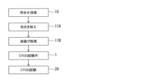
- FIG. 3 is a diagram illustrating an example of a processing procedure according to an embodiment based on the present invention. It is a figure which shows the test piece after notch processing.
- (a) is a side view
- (b) is a sectional view taken along line XX in (a)
- (c) is an enlarged view of the base side of the notch
- (d) is an enlarged view of the tip of the notch.
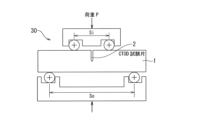
- It is a schematic diagram explaining a CTOD test.
- This embodiment is a method for producing a test piece for a three-point bending CTOD test. As shown in FIG. 1, the test piece is manufactured by performing butt welding 10, notch processing 11A, and reverse bending processing 11B in this order. Then, the produced test piece 1 is subjected to a three-point bending CTOD test 20, which is the main test. Then, the fracture surface of the test piece 1 after the test is measured to evaluate the toughness of the joint.
- the test piece 1 of the CTOD test 20 is a steel plate obtained by butt welding steel plates 1A and 1B each having a thickness of 125 mm or more.
- Reference numeral 1C is a welded portion.
- Butt welding may be performed using the welding conditions employed in the welded steel structure to be evaluated.
- the groove shape of the butt welded joint is, for example, a V-shape or a K-shape.
- the thickness of the test piece 1 is not particularly limited as long as it is 125 mm or more.
- the width W of the test piece 1 is also 125 mm or more.
- the plate width W and the plate thickness B may be different as long as both the plate thickness B and the plate width W are 125 mm or more.
- the symbol L is the length of the test piece 1, which is, for example, 600 mm.
- the upper limit of the thickness of the test piece 1 is, for example, 200 mm.
- the material of the test piece 1 is not particularly limited as long as it is a steel material. In this embodiment, the material of the test piece 1 is, for example, a steel type (steel plate) such as SM490B having a tensile strength of 490 MPa or more.
- a notch process 11A and a reverse bending process 11B are performed on a test piece 1 made of a butt welded joint as pretreatment.
- the test piece 1 is used as a test piece for the three-point bending CTOD test 20.
- the notch process 11A and the reverse bending process 11B are performed under conditions based on ISO15653 (2016).
- a slit-shaped notch 2 (mechanical notch) with a predetermined depth is formed in the welded portion 1C of the test piece 1.
- the notch 2 is formed from the plate surface (upper surface) of the test piece 1 in the plate width direction.
- the notch 2 is formed along the weld fusion line.
- the notch 2 shown in FIG. 2 has, for example, a depth (notch length) am in the range of 48 to 60 mm.
- the width of the notch 2 is 2 mm (see FIG. 2(c)). Also.
- the shape of the tip 2a of the notch 2 was set to have an angle of 60 degrees and a radius of curvature of 0.1 mm (see FIG. 2(d)).
- FIG. 2 a case is illustrated in which the base portion 2b of the notch 2 is also processed to change its shape.
- the shape of the notch 2 is not limited to the shape shown in FIG. 2 as long as it is formed in accordance with ISO15653 (2016).
- the formation position N of the notch 2 should just be formed in the welded part 1C, as shown in FIG.
- a notch 2 may be formed as shown in FIG. 3(a). In other words, the notch 2 may be formed at a position where the outline of the welded portion 1C extends in the plate thickness direction.
- the reverse bending process 11B uses, for example, the same testing machine as the three-point bending CTOD test 20.
- four-point bending is performed in accordance with ISO15653 (2016).
- a testing machine 30 as shown in FIG. 4 four-point bending is performed in the direction in which the notch 2 closes.
- a fatigue crack 3 is introduced at the tip of the notch 2 as a pretreatment (see FIG. 5).
- the tip of the notch 2 extends over the entire area of the test piece 1 in the thickness direction, as shown in FIG. 2(b).
- the parameter Lr was determined from the ratio between the determined maximum load Prb and the limit load PL.
- af is the average length of the fatigue cracks introduced into the notch 2, and the minimum length of the fatigue crack is afmin. Note that this fatigue crack length af was measured after the CTOD test 20.
- CTOD exam 20 As described above, a fatigue crack is introduced into the mechanical notch 2 to prepare a test piece 1 for the CTOD test 20. Then, a CTOD test 20 is performed on the prepared test piece 1 using a known method with a configuration as shown in FIG. Then, the fracture toughness of the welded portion 1C is evaluated from the fracture surface of the test piece 1. Note that the dimensions shown in FIG. 5 are just examples.
- This embodiment relates to a test piece 1 taken from a welded joint with a plate thickness of 125 mm or more.
- a reverse bending method (reverse bending process 11B) is performed as a pretreatment for introducing fatigue cracks.
- the conditions are such that equations (1) and (2) are satisfied.
- residual stress is uniformly removed both inside and on the surface of the test piece 1.
- straight propagation of fatigue cracks can be ensured. If the method for manufacturing the test piece 1 based on this embodiment is used, effective test results can be obtained in the three-point bending CTOD test 20 for the test piece 1 made of a welded joint with a plate thickness of 125 mm or more.
- the present disclosure can also take the following configuration.
- reverse bending process 11B is performed in the direction in which the notch 2 formed by the notch process 11A closes, and a fatigue crack is introduced into the notch 2 for testing.
- the reverse bending process 11B satisfies the following equations (1) and (2).
- Prb Maximum load in reverse bending process 11B
- PL Limit load in reverse bending process 11B
- af Length of fatigue crack introduced in reverse bending process 11B
- wrb Compressive plastic region size generated in reverse bending process 11B .
- Test piece 1 was prepared from a steel plate made of material SM490B. As for the thickness and width of the test piece 1, a test piece 1 having a square cross section with one side of 150 mm or 125 mm was used. Each test piece 1 was butt welded by FCAW (heat input 3.0 kJ/mm) welding using welding wire KC-60 to produce a butt welded joint as test piece 1. Notch machining 11A was performed under conditions based on ISO15653 (2018). Then, a notch 2 was formed in the test piece 1.
- FCAW heat input 3.0 kJ/mm
- Test piece 2 Notch 10 Butt welding 11A Notch processing 11B Reverse bending treatment 20 CTOD test 30 Testing machine 60 Angle B Plate thickness W Plate width af Fatigue crack growth amount
Landscapes
- Physics & Mathematics (AREA)
- Health & Medical Sciences (AREA)
- Life Sciences & Earth Sciences (AREA)
- Chemical & Material Sciences (AREA)
- Analytical Chemistry (AREA)
- Biochemistry (AREA)
- General Health & Medical Sciences (AREA)
- General Physics & Mathematics (AREA)
- Immunology (AREA)
- Pathology (AREA)
- Investigating Strength Of Materials By Application Of Mechanical Stress (AREA)
Abstract
より確実に疲労き裂の直線性を担保可能な、3点曲げCTOD試験用の試験片を提供する。鋼板を突合わせ溶接した突合せ溶接継手からなる、3点曲げCTOD試験(20)の試験片(1)を作製する方法である。試験片(1)の板厚を125mm以上とし、試験片(1)に切欠き加工(11A)を行った後に、切欠き加工(11A)で形成した切欠き(2)が閉じる方向に逆曲げ処理(11B)を行って、切欠き(2)に疲労き裂を導入して試験片(1)とし、逆曲げ処理(11B)が下記(1)式及び(2)式を満足する。 0.9≦ Lr (=Prb/PL) ≦1.0 ・・・(1) 1.0≦ k (=af /wrb) ≦1.5 ・・・(2)
Description
本発明は、溶接鋼構造物の破壊靭性値を測定する3点曲げCTOD試験の試験片の作製方法に関する。
本発明は、突合せ溶接継手からなる試験片に対し、破壊靭性試験規格ISO 15653(2018)に準拠した技術である。具体的には、本発明は、切欠き加工を行った後に逆曲げ処理(疲労き裂導入処理)を行うことで、CTOD試験用の溶接部を有する試験片を作製する技術に係る。本発明は、上記試験片が厚板からなる場合に有効な技術である。
一般に、板厚が20mm~50mm程度の厚鋼板を用いた溶接鋼構造物の継手靭性評価には、例えばISO15653(2018)等に準拠した3点曲げCTOD試験が用いられる。このとき、溶接継手から採取された試験片については、3点曲げCTOD試験を行う際に、破壊靭性評価のために重要な疲労き裂の直線性を担保する必要がある。このため、試験片に前処理を施すことが一般的である。その前処理は、切欠き加工で形成した切欠きの先端部に、疲労き裂を導入する処理である。
前処理としては、例えば、特許文献1や特許文献2に記載のような、切欠きに対して逆曲げ処理を施す逆曲げ法がある。
前処理としては、例えば、特許文献1や特許文献2に記載のような、切欠きに対して逆曲げ処理を施す逆曲げ法がある。
ISO15653(2018)には、3点曲げCTOD試験の前処理の1つとして逆曲げ法が開示されている。このISO15653(2018)には、逆曲げ法について、下記(3)式及び(4)式の条件で実施することが推奨されている。
0.6≦ Lr (=Prb/PL) ≦1.0 ・・・(3)
1.0≦ k (=af /wrb) ≦1.5 ・・・(4)
ここで、
Prb:逆曲げ処理での最大荷重
PL:逆曲げ処理でのリミットロード
af:逆曲げ処理で導入される疲労き裂の長さ
wrb:逆曲げ処理で生じる圧縮塑性域寸法
である。
0.6≦ Lr (=Prb/PL) ≦1.0 ・・・(3)
1.0≦ k (=af /wrb) ≦1.5 ・・・(4)
ここで、
Prb:逆曲げ処理での最大荷重
PL:逆曲げ処理でのリミットロード
af:逆曲げ処理で導入される疲労き裂の長さ
wrb:逆曲げ処理で生じる圧縮塑性域寸法
である。
しかし、発明者は、種々の検討により、次の知見を得た。すなわち、発明者は、ISO15653(2018)に準拠して、試験片に対し前処理として逆曲げ処理を施した。しかし、発明者は、このような前処理を施しても、試験片の板厚によっては、試験片への前処理が有効に働かない場合があるとの知見を得た。前処理が有効に働かない場合には、疲労き裂の直線性が担保できなくなる。この場合、3点曲げCTOD試験の試験結果が無効となる。
本発明は、上記のような知見に基づきなされたものである。本発明は、より確実に疲労き裂の直線性を担保可能な、3点曲げCTOD試験用の試験片を提供できることを目的とする。
特許文献1や2などの公知文献は、試験片の板厚が20mm~50mmの範囲での試験を想定している。すなわち、これらの文献では、板厚が100mmを超える場合について、検討がされていない。
そして、発明者らの検討によれば、板厚125mm以上の溶接継手から採取した試験片について次のことが判明した。すなわち、上述の(3)式及び(4)式の条件で逆曲げ処理を施した場合に、試験結果が無効となる場合がある、との知見を得た。具体的には、発明者は、推奨条件の一部の範囲(Lr=0.6等)を採用した場合、前処理が有効に働かず疲労き裂の直線性が担保できなくなるとの知見を得た。そして、疲労き裂の直線性が担保出来ない場合、試験結果が無効となる。更に、発明者は、種々の検討を行うことで、板厚125mm以上の突合せ溶接継手を試験片とする場合における、適正な逆曲げ処理の条件を見いだして、本発明をなした。
そして、発明者らの検討によれば、板厚125mm以上の溶接継手から採取した試験片について次のことが判明した。すなわち、上述の(3)式及び(4)式の条件で逆曲げ処理を施した場合に、試験結果が無効となる場合がある、との知見を得た。具体的には、発明者は、推奨条件の一部の範囲(Lr=0.6等)を採用した場合、前処理が有効に働かず疲労き裂の直線性が担保できなくなるとの知見を得た。そして、疲労き裂の直線性が担保出来ない場合、試験結果が無効となる。更に、発明者は、種々の検討を行うことで、板厚125mm以上の突合せ溶接継手を試験片とする場合における、適正な逆曲げ処理の条件を見いだして、本発明をなした。
すなわち、課題解決のために、本発明の一態様は、鋼板を突合わせ溶接した突合せ溶接継手からなる、3点曲げCTOD試験の試験片を作製する方法であって、上記試験片の板厚を125mm以上とし、上記試験片に切欠き加工を行った後に、上記切欠き加工で形成した切欠きが閉じる方向に逆曲げ処理を行って、上記切欠きに疲労き裂を導入して試験片とし、上記逆曲げ処理が下記(1)式及び(2)式を満足する、ことを要旨とする。
0.9≦ Lr (=Prb/PL) ≦1.0 ・・・(1)
1.0≦ k (=af /wrb) ≦1.5 ・・・(2)
ここで、
Prb:逆曲げ処理での最大荷重
PL:逆曲げ処理でのリミットロード
af:逆曲げ処理で導入される疲労き裂の長さ
wrb:逆曲げ処理で生じる圧縮塑性域寸法
である。
0.9≦ Lr (=Prb/PL) ≦1.0 ・・・(1)
1.0≦ k (=af /wrb) ≦1.5 ・・・(2)
ここで、
Prb:逆曲げ処理での最大荷重
PL:逆曲げ処理でのリミットロード
af:逆曲げ処理で導入される疲労き裂の長さ
wrb:逆曲げ処理で生じる圧縮塑性域寸法
である。
本発明の態様によれば、板厚125mm以上の突合せ溶接継手からなる試験片であっても、適正な疲労き裂が導入された試験片を提供可能となる。この結果、本発明の態様によれば、より確実に疲労き裂の直線性を担保可能な3点曲げCTOD試験用の試験片を提供できる。そして、この場合には、3点曲げCTOD試験をより適正に実行可能となる。
例えば、本発明の態様によれば、板厚125mm以上の厚鋼板溶接継手における3点曲げCTOD試験の試験片作成のための逆曲げ条件について、適正な範囲が提供可能となる。その結果、本発明の態様によれば、CTOD試験の試験結果が無効にならずに、構造物の安全性を適切に評価できるといった効果を奏する。すなわち、本発明の態様によれば、産業上格段に優れた効果を奏する。
例えば、本発明の態様によれば、板厚125mm以上の厚鋼板溶接継手における3点曲げCTOD試験の試験片作成のための逆曲げ条件について、適正な範囲が提供可能となる。その結果、本発明の態様によれば、CTOD試験の試験結果が無効にならずに、構造物の安全性を適切に評価できるといった効果を奏する。すなわち、本発明の態様によれば、産業上格段に優れた効果を奏する。
以下、本発明の実施形態について図面を参照して説明する。
(知見)
発明者は次の知見を得た。ISO15653(2018)規格推奨範囲(上述の(3)式及び(4)式の条件を参照)の逆曲げ条件でも、板厚125mm以上の材料では前処理が有効に働かない場合があった。その場合には、導入される疲労き裂の直線性が担保できなくなり、試験結果が無効になった。発明者は、その原因を調査するため、有限要素解析による逆曲げ処理実施後の試験片に生じる逆曲げ塑性域(圧縮塑性域)を求めた。そして、発明者は、有限要素解析で得られた逆曲げ塑性域と、ISO15653(2018)規格で計算される理論逆曲げ塑性域との比較を行うことで、次の新たな知見を得た。
(知見)
発明者は次の知見を得た。ISO15653(2018)規格推奨範囲(上述の(3)式及び(4)式の条件を参照)の逆曲げ条件でも、板厚125mm以上の材料では前処理が有効に働かない場合があった。その場合には、導入される疲労き裂の直線性が担保できなくなり、試験結果が無効になった。発明者は、その原因を調査するため、有限要素解析による逆曲げ処理実施後の試験片に生じる逆曲げ塑性域(圧縮塑性域)を求めた。そして、発明者は、有限要素解析で得られた逆曲げ塑性域と、ISO15653(2018)規格で計算される理論逆曲げ塑性域との比較を行うことで、次の新たな知見を得た。
すなわち、Lrが0.6~0.9の範囲では、試験片における板厚中心の逆曲げ塑性域は理論逆曲げ塑性域と良く一致している。しかし、Lrが0.6~0.9の範囲では、試験片表面の逆曲げ塑性域は理論逆曲げ塑性域よりも小さい。つまり、試験片表面では残留応力が除去されている領域が理論式より小さく、残留応力が残る可能性が高いことが分かった。このような状況で疲労き裂を導入すると、残留応力の不均一性のために疲労き裂の直進性が担保できない。担保できない場合、試験結果が無効となる。
一方、Lrが0.9~1.0の範囲では、試験片における板厚中心及び試験片表面の逆曲げ塑性域は、ともに理論逆曲げ塑性域と良く一致している。つまり、試験片の内部、表面共に残留応力が均一に除去されている。この状況では、残留応力が均一に除去されているため、疲労き裂の直進性が担保できる。結果、試験結果が有効となる。この傾向は、板厚が大きくなるほど、より顕著に表れる。
一方、Lrが0.9~1.0の範囲では、試験片における板厚中心及び試験片表面の逆曲げ塑性域は、ともに理論逆曲げ塑性域と良く一致している。つまり、試験片の内部、表面共に残留応力が均一に除去されている。この状況では、残留応力が均一に除去されているため、疲労き裂の直進性が担保できる。結果、試験結果が有効となる。この傾向は、板厚が大きくなるほど、より顕著に表れる。
以上のことから、発明者は、板厚125mm以上の突合せ溶接継手からなる試験片に対する逆曲げ処理においては、次の新たな知見を得た。すなわち、Lrの条件は、0.9以上1.0以下が好適である、という新たに知見した。
また、切欠き加工時の狙いについて、逆曲げ荷重に関するパラメータLrは、試験片加工時に精度よく指定できる。このため、上記範囲の上限である、0.99~1.0、さらには上限のLr=1.0とすることが好ましい。一方、疲労き裂長さに関するパラメータkは、CTOD試験を行った後にしか精度良く分からない。しかし、発明者は、多少の尤度をもって最適条件の中央となるk=1.2近傍で、CTOD試験の試験結果の精度が良い、との新たな知見も得た。k=1.2近傍とは、例えば、kが1.1以上1.3以下の範囲である。
また、切欠き加工時の狙いについて、逆曲げ荷重に関するパラメータLrは、試験片加工時に精度よく指定できる。このため、上記範囲の上限である、0.99~1.0、さらには上限のLr=1.0とすることが好ましい。一方、疲労き裂長さに関するパラメータkは、CTOD試験を行った後にしか精度良く分からない。しかし、発明者は、多少の尤度をもって最適条件の中央となるk=1.2近傍で、CTOD試験の試験結果の精度が良い、との新たな知見も得た。k=1.2近傍とは、例えば、kが1.1以上1.3以下の範囲である。
(構成)
本実施形態は、3点曲げCTOD試験の試験片を作製する方法である。
試験片の作製は、図1に示すように、突合せ溶接10、切欠き加工11A、逆曲げ処理11Bを、この順番に実行して作製される。
そして、作製された試験片1に対し、本試験である3点曲げCTOD試験20を施す。そして、試験後の試験片1の破面を測定し、継手部の靭性を評価する。
本実施形態は、3点曲げCTOD試験の試験片を作製する方法である。
試験片の作製は、図1に示すように、突合せ溶接10、切欠き加工11A、逆曲げ処理11Bを、この順番に実行して作製される。
そして、作製された試験片1に対し、本試験である3点曲げCTOD試験20を施す。そして、試験後の試験片1の破面を測定し、継手部の靭性を評価する。
<突合せ溶接10>
CTOD試験20の試験片1は、図2のように、板厚125mm以上の鋼板1A,1B同士を突合せ溶接した鋼板である。符号1Cは、溶接部である。突合せ溶接については、評価対象の溶接鋼構造物で採用する溶接条件を用いて実行すれば良い。なお、突合せ溶接継手の開先形状は、例えばレ形やK形である。
試験片1の板厚は、125mm以上であれば特に限定はない。
本実施形態の試験片1は、正方形断面とする。正方形断面の場合、板幅W=板厚Bとなる。すなわち、試験片1の幅Wも125mm以上となっている。試験片1は、板厚B、板幅Wともに125mm以上であれば、板幅Wと板厚Bとが異なっていても良い。図2中、符号Lは、試験片1の長さで、例えば600mmとなっている。
試験片1の板厚の上限は、例えば200mmである。
また、試験片1の材料は、鋼材であれば特に限定はない。本実施形態では、試験片1の材料は、例えば、SM490Bのような引張強度490MPa以上の鋼種(鋼板)を対象とする。
CTOD試験20の試験片1は、図2のように、板厚125mm以上の鋼板1A,1B同士を突合せ溶接した鋼板である。符号1Cは、溶接部である。突合せ溶接については、評価対象の溶接鋼構造物で採用する溶接条件を用いて実行すれば良い。なお、突合せ溶接継手の開先形状は、例えばレ形やK形である。
試験片1の板厚は、125mm以上であれば特に限定はない。
本実施形態の試験片1は、正方形断面とする。正方形断面の場合、板幅W=板厚Bとなる。すなわち、試験片1の幅Wも125mm以上となっている。試験片1は、板厚B、板幅Wともに125mm以上であれば、板幅Wと板厚Bとが異なっていても良い。図2中、符号Lは、試験片1の長さで、例えば600mmとなっている。
試験片1の板厚の上限は、例えば200mmである。
また、試験片1の材料は、鋼材であれば特に限定はない。本実施形態では、試験片1の材料は、例えば、SM490Bのような引張強度490MPa以上の鋼種(鋼板)を対象とする。
<前処理>
本実施形態では、突合せ溶接継手からなる試験片1に対し、前処理として切欠き加工11Aと逆曲げ処理11Bとを施す。これによって、試験片1を、3点曲げCTOD試験20の試験片とする。切欠き加工11Aと逆曲げ処理11Bは、ISO15653(2018)に準拠した条件にて実行する。
本実施形態では、突合せ溶接継手からなる試験片1に対し、前処理として切欠き加工11Aと逆曲げ処理11Bとを施す。これによって、試験片1を、3点曲げCTOD試験20の試験片とする。切欠き加工11Aと逆曲げ処理11Bは、ISO15653(2018)に準拠した条件にて実行する。
<切欠き加工11A>
切欠き加工11Aでは、試験片1の溶接部1Cに対し、所定深さのスリット状の切欠き2(機械切欠き)を形成する。切欠き2は、例えば、図2のように、試験片1の板表面(上面)から、板幅方向に向けて形成される。その切欠き2は、溶接融合線に沿って形成される。
図2に示す切欠き2は、例えば、深さ(切欠き長さ)amを48~60mmの範囲とする。また、切欠き2の幅を2mmとしている(図2(c)参照)。また。切欠き2の先端部2aの形状は、角度60度、先端の曲率半径0.1mmとした(図2(d)参照)。図2では、切欠き2の付け根部2bも形状を変える加工を施す場合が例示されている。しかし、切欠き2の形状は、ISO15653(2018)に準拠して形成されていれば、図2の形状に限定されない。
切欠き2の形成位置Nは、図3のように、溶接部1Cに形成されていれば良い。溶接の開先形状が、レ形やk形の場合には、図3(a)のように切欠き2を形成すればよい。つまり、溶接部1Cの輪郭が板厚方向に延びる位置に、切欠き2を形成すればよい。
切欠き加工11Aでは、試験片1の溶接部1Cに対し、所定深さのスリット状の切欠き2(機械切欠き)を形成する。切欠き2は、例えば、図2のように、試験片1の板表面(上面)から、板幅方向に向けて形成される。その切欠き2は、溶接融合線に沿って形成される。
図2に示す切欠き2は、例えば、深さ(切欠き長さ)amを48~60mmの範囲とする。また、切欠き2の幅を2mmとしている(図2(c)参照)。また。切欠き2の先端部2aの形状は、角度60度、先端の曲率半径0.1mmとした(図2(d)参照)。図2では、切欠き2の付け根部2bも形状を変える加工を施す場合が例示されている。しかし、切欠き2の形状は、ISO15653(2018)に準拠して形成されていれば、図2の形状に限定されない。
切欠き2の形成位置Nは、図3のように、溶接部1Cに形成されていれば良い。溶接の開先形状が、レ形やk形の場合には、図3(a)のように切欠き2を形成すればよい。つまり、溶接部1Cの輪郭が板厚方向に延びる位置に、切欠き2を形成すればよい。
<逆曲げ処理11B>
逆曲げ処理11Bは、例えば、3点曲げCTOD試験20と同じ試験機を使用する。例えば、逆曲げ処理11Bでは、ISO15653(2018)に準拠して4点曲げを施す。具体的には、図4のような試験機30を用いて、切欠き2が閉じる方向に4点曲げを施す。これにより、前処理として、切欠き2の先端部に疲労き裂3を導入する(図5参照)。
ここで、切欠き2の先端部は、図2(b)のように、試験片1の板厚方向全域に延在している。
逆曲げ処理11Bは、例えば、3点曲げCTOD試験20と同じ試験機を使用する。例えば、逆曲げ処理11Bでは、ISO15653(2018)に準拠して4点曲げを施す。具体的には、図4のような試験機30を用いて、切欠き2が閉じる方向に4点曲げを施す。これにより、前処理として、切欠き2の先端部に疲労き裂3を導入する(図5参照)。
ここで、切欠き2の先端部は、図2(b)のように、試験片1の板厚方向全域に延在している。
このとき、本実施形態では、逆曲げ処理11Bの逆曲げ条件として、(1)式及び(2)式を満足する条件とする。他の条件は、ISO15653(2018)に準拠した条件とする。
0.9≦ Lr (=Prb/PL) ≦1.0 ・・・(1)
1.0≦ k (=af /wrb) ≦1.5 ・・・(2)
ここで、
Prb:逆曲げ処理11Bでの最大荷重
PL:逆曲げ処理11Bでのリミットロード
af:逆曲げ処理11Bで導入される疲労き裂の長さ
wrb:逆曲げ処理11Bで生じる圧縮塑性域寸法
である。
0.9≦ Lr (=Prb/PL) ≦1.0 ・・・(1)
1.0≦ k (=af /wrb) ≦1.5 ・・・(2)
ここで、
Prb:逆曲げ処理11Bでの最大荷重
PL:逆曲げ処理11Bでのリミットロード
af:逆曲げ処理11Bで導入される疲労き裂の長さ
wrb:逆曲げ処理11Bで生じる圧縮塑性域寸法
である。
例えば、クリップゲージを切欠き2の端部(付け根側)に取り付けて、逆曲げ時の切欠き2の開口量が所定値となるように制御する。また、その制御を行いつつ、逆曲げ時の最大荷重Prbを測定する。
また、リミットロードPLは、下記式によって求めることができる。
PL ={B(W -am)2/(So -Si)}・σ
ここで、
B:試験片1の板厚
W:試験片1の板幅
am:切欠き長さ(切欠き2の深さ)
So:4点曲げの外側のスパン
Si:4点曲げの内側のスパン
σ:試験片1の室温での降伏応力
である。
また、リミットロードPLは、下記式によって求めることができる。
PL ={B(W -am)2/(So -Si)}・σ
ここで、
B:試験片1の板厚
W:試験片1の板幅
am:切欠き長さ(切欠き2の深さ)
So:4点曲げの外側のスパン
Si:4点曲げの内側のスパン
σ:試験片1の室温での降伏応力
である。
そして、求めた最大荷重PrbとリミットロードPLとの比から、パラメータLrを求めた。
また、圧縮塑性域寸法wrbは、下記式から算出した。
wrb =(π/8)・(Krb/(L・σ))2
ここで、
σ:試験片1の室温での降伏応力
L:ノッチ拘束係数(例えば、2.3)
Krb:応力拡大係数
である。
afは、切欠き2に導入された疲労き裂の長さの平均値であり、長さが最小の疲労き裂長さをafminとする。なお、この疲労き裂長さafは、CTOD試験20の試験後に測定した。
また、圧縮塑性域寸法wrbは、下記式から算出した。
wrb =(π/8)・(Krb/(L・σ))2
ここで、
σ:試験片1の室温での降伏応力
L:ノッチ拘束係数(例えば、2.3)
Krb:応力拡大係数
である。
afは、切欠き2に導入された疲労き裂の長さの平均値であり、長さが最小の疲労き裂長さをafminとする。なお、この疲労き裂長さafは、CTOD試験20の試験後に測定した。
(CTOD試験20)
上記のように、機械切欠き2に疲労き裂を導入してCTOD試験20用の試験片1を作製する。
そして、作製した試験片1に対して、図5のような構成で、公知の方法でCTOD試験20を行う。そして、試験片1の破面から、溶接部1Cの破壊靱性を評価する。なお、図5に示す寸法は例示である。
上記のように、機械切欠き2に疲労き裂を導入してCTOD試験20用の試験片1を作製する。
そして、作製した試験片1に対して、図5のような構成で、公知の方法でCTOD試験20を行う。そして、試験片1の破面から、溶接部1Cの破壊靱性を評価する。なお、図5に示す寸法は例示である。
(効果)
本実施形態は、板厚125mm以上の溶接継手から採取した試験片1に関する。本実施形態では、3点曲げCTOD試験20用の試験片1を作製する際に、疲労き裂を導入する前処理としての逆曲げ法(逆曲げ処理11B)を施す。このとき、逆曲げ法において、(1)式及び(2)式を満足する条件とする。これにより、本実施形態では、試験片1の内部及び表面共に、残留応力が均一に除去される。この結果、本実施形態では、疲労き裂の直進性が担保できるようになる。
そして、本実施形態に基づいた試験片1の作製方法を用いれば、板厚125mm以上の溶接継手からなる試験片1に対する3点曲げCTOD試験20において、有効な試験結果を得ることができる。
本実施形態は、板厚125mm以上の溶接継手から採取した試験片1に関する。本実施形態では、3点曲げCTOD試験20用の試験片1を作製する際に、疲労き裂を導入する前処理としての逆曲げ法(逆曲げ処理11B)を施す。このとき、逆曲げ法において、(1)式及び(2)式を満足する条件とする。これにより、本実施形態では、試験片1の内部及び表面共に、残留応力が均一に除去される。この結果、本実施形態では、疲労き裂の直進性が担保できるようになる。
そして、本実施形態に基づいた試験片1の作製方法を用いれば、板厚125mm以上の溶接継手からなる試験片1に対する3点曲げCTOD試験20において、有効な試験結果を得ることができる。
(その他)
本開示は、次の構成も取り得る。
(1)鋼板を突合わせ溶接した突合せ溶接継手からなる、3点曲げCTOD試験20の試験片1を作製する方法であって、
上記試験片1の板厚を125mm以上とし、
上記試験片1に切欠き加工11Aを行った後に、上記切欠き加工11Aで形成した切欠き2が閉じる方向に逆曲げ処理11Bを行って、上記切欠き2に疲労き裂を導入して試験片1とし、
上記逆曲げ処理11Bが下記(1)式及び(2)式を満足する。
0.9≦ Lr (=Prb/PL) ≦1.0 ・・・(1)
1.0≦ k (=af /wrb) ≦1.5 ・・・(2)
ここで、
Prb:逆曲げ処理11Bでの最大荷重
PL:逆曲げ処理11Bでのリミットロード
af:逆曲げ処理11Bで導入される疲労き裂の長さ
wrb:逆曲げ処理11Bで生じる圧縮塑性域寸法
である。
本開示は、次の構成も取り得る。
(1)鋼板を突合わせ溶接した突合せ溶接継手からなる、3点曲げCTOD試験20の試験片1を作製する方法であって、
上記試験片1の板厚を125mm以上とし、
上記試験片1に切欠き加工11Aを行った後に、上記切欠き加工11Aで形成した切欠き2が閉じる方向に逆曲げ処理11Bを行って、上記切欠き2に疲労き裂を導入して試験片1とし、
上記逆曲げ処理11Bが下記(1)式及び(2)式を満足する。
0.9≦ Lr (=Prb/PL) ≦1.0 ・・・(1)
1.0≦ k (=af /wrb) ≦1.5 ・・・(2)
ここで、
Prb:逆曲げ処理11Bでの最大荷重
PL:逆曲げ処理11Bでのリミットロード
af:逆曲げ処理11Bで導入される疲労き裂の長さ
wrb:逆曲げ処理11Bで生じる圧縮塑性域寸法
である。
次に、本実施形態に基づく実施例について説明する。
(試験片1)
材料SM490Bからなる鋼板から試験片1を作製した。試験片1の板厚及び板幅として、一辺が150mm又は125mmからなる正方形断面の試験片1を用いた。各試験片1は、溶接ワイヤKC-60 を用いたFCAW(入熱3.0kJ/mm)溶接で突合せ溶接を行って、試験片1としての突合せ溶接継手を作製した。
切欠き加工11Aでは、ISO15653(2018)に準拠した条件で実行した。そして、試験片1に切欠き2を形成した。
(試験片1)
材料SM490Bからなる鋼板から試験片1を作製した。試験片1の板厚及び板幅として、一辺が150mm又は125mmからなる正方形断面の試験片1を用いた。各試験片1は、溶接ワイヤKC-60 を用いたFCAW(入熱3.0kJ/mm)溶接で突合せ溶接を行って、試験片1としての突合せ溶接継手を作製した。
切欠き加工11Aでは、ISO15653(2018)に準拠した条件で実行した。そして、試験片1に切欠き2を形成した。
次に、表1、表2に示す条件にて、各試験片1に対し逆曲げ処理11Bを施した。そして、CTOD試験片1を作製した。
そして、各試験片1にCTOD試験20を行い、試験後の破面を測定して、各試験片1の疲労き裂進展量af(=a0-am)を求めた。その最小値afminを表1、表2に示す。
表1、表2に試験結果を示す。
そして、各試験片1にCTOD試験20を行い、試験後の破面を測定して、各試験片1の疲労き裂進展量af(=a0-am)を求めた。その最小値afminを表1、表2に示す。
表1、表2に試験結果を示す。


(評価)
疲労き裂の直進性は、疲労き裂進展量afの最小値afminに基づき評価した。そして、最小値afminが、2.5%W以上の場合に、疲労き裂の直線性が有効と判定した。
ここで、板厚125mmの場合、2.5%Wは3.1mmとし、板厚150mmの場合、2.5%Wは3.7mmとした。
表2から分かるように、Lrが0.9以上1.0以下の範囲である各実施例では、疲労き裂の直進性の判定結果が有効判定となった。
一方、Lrが0.7以下の比較例の条件ではすべて疲労き裂の直進性の判定結果が無効判定となった。
このように、板厚が125mm以上の場合、Lrを0.9以上1.0以下の範囲に限定して実行する必要があることが分かった。
疲労き裂の直進性は、疲労き裂進展量afの最小値afminに基づき評価した。そして、最小値afminが、2.5%W以上の場合に、疲労き裂の直線性が有効と判定した。
ここで、板厚125mmの場合、2.5%Wは3.1mmとし、板厚150mmの場合、2.5%Wは3.7mmとした。
表2から分かるように、Lrが0.9以上1.0以下の範囲である各実施例では、疲労き裂の直進性の判定結果が有効判定となった。
一方、Lrが0.7以下の比較例の条件ではすべて疲労き裂の直進性の判定結果が無効判定となった。
このように、板厚が125mm以上の場合、Lrを0.9以上1.0以下の範囲に限定して実行する必要があることが分かった。
ここで、本願が優先権を主張する、日本国特許出願2022-110976(2022年 7月11日出願)の全内容は、参照により本開示の一部をなす。ここでは、限られた数の実施形態を参照しながら説明したが、権利範囲はそれらに限定されるものではなく、上記の開示に基づく各実施形態の改変は当業者にとって自明なことである。
1 試験片
2 切欠き
10 突合せ溶接
11A 切欠き加工
11B 逆曲げ処理
20 CTOD試験
30 試験機
60 角度
B 板厚
W 板幅
af 疲労き裂進展量
2 切欠き
10 突合せ溶接
11A 切欠き加工
11B 逆曲げ処理
20 CTOD試験
30 試験機
60 角度
B 板厚
W 板幅
af 疲労き裂進展量
Claims (1)
- 鋼板を突合わせ溶接した突合せ溶接継手からなる、3点曲げCTOD試験の試験片を作製する方法であって、
上記試験片の板厚を125mm以上とし、
上記試験片に切欠き加工を行った後に、上記切欠き加工で形成した切欠きが閉じる方向に逆曲げ処理を行って、上記切欠きに疲労き裂を導入して試験片とし、
上記逆曲げ処理が下記(1)式及び(2)式を満足する、
3点曲げCTOD試験片の作製方法。
0.9≦ Lr (=Prb/PL) ≦1.0 ・・・(1)
1.0≦ k (=af /wrb) ≦1.5 ・・・(2)
ここで、
Prb:逆曲げ処理での最大荷重
PL:逆曲げ処理でのリミットロード
af:逆曲げ処理で導入される疲労き裂の長さ
wrb:逆曲げ処理で生じる圧縮塑性域寸法
である。
Priority Applications (1)
| Application Number | Priority Date | Filing Date | Title |
|---|---|---|---|
| JP2023550542A JP7371822B1 (ja) | 2022-07-11 | 2023-06-05 | 3点曲げctod試験片の作製方法 |
Applications Claiming Priority (2)
| Application Number | Priority Date | Filing Date | Title |
|---|---|---|---|
| JP2022110976 | 2022-07-11 | ||
| JP2022-110976 | 2022-07-11 |
Publications (1)
| Publication Number | Publication Date |
|---|---|
| WO2024014181A1 true WO2024014181A1 (ja) | 2024-01-18 |
Family
ID=89536620
Family Applications (1)
| Application Number | Title | Priority Date | Filing Date |
|---|---|---|---|
| PCT/JP2023/020864 Ceased WO2024014181A1 (ja) | 2022-07-11 | 2023-06-05 | 3点曲げctod試験片の作製方法 |
Country Status (1)
| Country | Link |
|---|---|
| WO (1) | WO2024014181A1 (ja) |
Cited By (1)
| Publication number | Priority date | Publication date | Assignee | Title |
|---|---|---|---|---|
| CN120121426A (zh) * | 2025-03-18 | 2025-06-10 | 洛阳船舶材料研究所(中国船舶集团有限公司第七二五研究所) | 一种海工钢试样加工缺口的余料辅助取出装置及取出方法 |
Citations (3)
| Publication number | Priority date | Publication date | Assignee | Title |
|---|---|---|---|---|
| JP2015135324A (ja) * | 2013-12-20 | 2015-07-27 | 新日鐵住金株式会社 | 高強度厚鋼板の脆性き裂伝播停止特性の判定方法 |
| WO2018088273A1 (ja) * | 2016-11-09 | 2018-05-17 | 新日鐵住金株式会社 | Ctod試験片の作製方法および塑性歪調整用治具 |
| WO2019102912A1 (ja) * | 2017-11-22 | 2019-05-31 | Jfeスチール株式会社 | 厚鋼板の脆性き裂伝播停止性能の評価方法 |
-
2023
- 2023-06-05 WO PCT/JP2023/020864 patent/WO2024014181A1/ja not_active Ceased
Patent Citations (3)
| Publication number | Priority date | Publication date | Assignee | Title |
|---|---|---|---|---|
| JP2015135324A (ja) * | 2013-12-20 | 2015-07-27 | 新日鐵住金株式会社 | 高強度厚鋼板の脆性き裂伝播停止特性の判定方法 |
| WO2018088273A1 (ja) * | 2016-11-09 | 2018-05-17 | 新日鐵住金株式会社 | Ctod試験片の作製方法および塑性歪調整用治具 |
| WO2019102912A1 (ja) * | 2017-11-22 | 2019-05-31 | Jfeスチール株式会社 | 厚鋼板の脆性き裂伝播停止性能の評価方法 |
Non-Patent Citations (3)
| Title |
|---|
| KAWABATA TOMOYA: "Innovation in weld fracture toughness evaluation method - History and achievements of technology to overcome pre-crack shape problem -", JOURNAL OF JAPAN SOCIETY OF NAVAL ARCHITECTS AND OCEAN ENGINEERS KANRIN, vol. 103, 1 January 2022 (2022-01-01), pages 16 - 25, XP093127835, DOI: https://doi.org/10.14856/kanrin.103.0_16 * |
| KITANO MOEICHI: "Clarification of conditions for improving fatigue pre-crack shape by reverse bending process and revision of WES standards", JOURNAL OF JAPAN SOCIETY OF NAVAL ARCHITECTS AND OCEAN ENGINEERS KANRIN, vol. 103, 1 January 2022 (2022-01-01), pages 39 - 44, XP093127846, DOI: https://doi.org/10.14856/kanrin.103.0_39 * |
| MORIKAGE YASUSHI, TAGAWA TETSUYA, HANDA TUNEHISA, IKEDA RINSEI : "Effect of pre-crack straightness control by various pre-treatments against weld residual stress in extremely thick welded joint CTOD specimen", WELDING SOCIETY NATIONAL CONFERENCE LECTURE SUMMARY, 2018 SPRING NATIONAL CONFERENCE, SESSION ID: 317, vol. 102, 1 April 2018 (2018-04-01), pages 142 - 143, XP093127824, DOI: https://doi.org/10.14920/jwstaikai.2018s.0_142 * |
Cited By (1)
| Publication number | Priority date | Publication date | Assignee | Title |
|---|---|---|---|---|
| CN120121426A (zh) * | 2025-03-18 | 2025-06-10 | 洛阳船舶材料研究所(中国船舶集团有限公司第七二五研究所) | 一种海工钢试样加工缺口的余料辅助取出装置及取出方法 |
Similar Documents
| Publication | Publication Date | Title |
|---|---|---|
| JP5218440B2 (ja) | 溶接金属の割れ感受性評価試験方法 | |
| CN114279785B (zh) | 激光熔覆涂层的抗裂性评价方法 | |
| EP3815836B1 (en) | Butt welded joint of steel material and method for manufacturing same | |
| KR20190014081A (ko) | 내응력 부식 균열성이 우수한 보일러용 전봉 강관 및 그의 제조 방법 | |
| JP6201803B2 (ja) | 低温靭性に優れたサブマージアーク溶接部 | |
| Singh et al. | Investigation on effect of welding parameters on solidification cracking of austenitic stainless steel 314 | |
| KR20200064138A (ko) | 후강판의 취성 균열 전파 정지 성능의 평가 방법 | |
| JP7371822B1 (ja) | 3点曲げctod試験片の作製方法 | |
| JP6369448B2 (ja) | 重ね隅肉アーク溶接継手、該重ね隅肉アーク溶接継手を有する自動車用構造部品 | |
| Tagawa et al. | Experimental proof of reverse bending technique for modifying weld residual stress in weld CTOD specimen and comparison of effect with other techniques | |
| JP4266417B2 (ja) | 中空ロール胴体用筒体の製造方法 | |
| TWI630054B (zh) | Welding joint and manufacturing method thereof | |
| JP6455210B2 (ja) | 低温靱性に優れたuoe鋼管 | |
| JP4274986B2 (ja) | 給油管用ステンレス鋼製溶接管 | |
| JP6677429B2 (ja) | 溶接鋼管及び給油管 | |
| Sultan et al. | Numerical simulation and experimental verification of CMOD in SENT specimen: application on FCGR of welded tool steel | |
| TWI654312B (zh) | Laser welded steel and manufacturing method thereof | |
| KR102443420B1 (ko) | 용접 구조물 | |
| KR101195733B1 (ko) | T형 용접 조인트 구조체에 있어서의 t 조인트부의 피로 특성 평가 방법 | |
| JP2001032043A (ja) | 耐破壊特性に優れたパイプライン用高強度溶接鋼管 | |
| JP6958391B2 (ja) | 鋼管 | |
| JP7862762B2 (ja) | 突合せ溶接継手、テーラードブランクおよび突合せ溶接継手の製造方法 | |
| JP7364867B2 (ja) | 溶接継手およびその製造方法 | |
| JP7339511B2 (ja) | 溶接継手およびその製造方法 | |
| JP2001269713A (ja) | ステンレス鋼溶接管及びその製造方法 |
Legal Events
| Date | Code | Title | Description |
|---|---|---|---|
| WWE | Wipo information: entry into national phase |
Ref document number: 2023550542 Country of ref document: JP |
|
| 121 | Ep: the epo has been informed by wipo that ep was designated in this application |
Ref document number: 23839357 Country of ref document: EP Kind code of ref document: A1 |
|
| NENP | Non-entry into the national phase |
Ref country code: DE |
|
| 122 | Ep: pct application non-entry in european phase |
Ref document number: 23839357 Country of ref document: EP Kind code of ref document: A1 |