WO2024013870A1 - 工作機械制御装置および工作機械制御プログラム - Google Patents
工作機械制御装置および工作機械制御プログラム Download PDFInfo
- Publication number
- WO2024013870A1 WO2024013870A1 PCT/JP2022/027518 JP2022027518W WO2024013870A1 WO 2024013870 A1 WO2024013870 A1 WO 2024013870A1 JP 2022027518 W JP2022027518 W JP 2022027518W WO 2024013870 A1 WO2024013870 A1 WO 2024013870A1
- Authority
- WO
- WIPO (PCT)
- Prior art keywords
- cutting
- condition
- vibration
- machine tool
- relative
- Prior art date
- Legal status (The legal status is an assumption and is not a legal conclusion. Google has not performed a legal analysis and makes no representation as to the accuracy of the status listed.)
- Ceased
Links
Images




Classifications
-
- G—PHYSICS
- G05—CONTROLLING; REGULATING
- G05B—CONTROL OR REGULATING SYSTEMS IN GENERAL; FUNCTIONAL ELEMENTS OF SUCH SYSTEMS; MONITORING OR TESTING ARRANGEMENTS FOR SUCH SYSTEMS OR ELEMENTS
- G05B19/00—Program-control systems
- G05B19/02—Program-control systems electric
- G05B19/18—Numerical control [NC], i.e. automatically operating machines, in particular machine tools, e.g. in a manufacturing environment, so as to execute positioning, movement or co-ordinated operations by means of program data in numerical form
- G05B19/4093—Numerical control [NC], i.e. automatically operating machines, in particular machine tools, e.g. in a manufacturing environment, so as to execute positioning, movement or co-ordinated operations by means of program data in numerical form characterised by part programming, e.g. entry of geometrical information as taken from a technical drawing, combining this with machining and material information to obtain control information, named part program, for the NC machine
-
- B—PERFORMING OPERATIONS; TRANSPORTING
- B23—MACHINE TOOLS; METAL-WORKING NOT OTHERWISE PROVIDED FOR
- B23Q—DETAILS, COMPONENTS, OR ACCESSORIES FOR MACHINE TOOLS, e.g. ARRANGEMENTS FOR COPYING OR CONTROLLING; MACHINE TOOLS IN GENERAL CHARACTERISED BY THE CONSTRUCTION OF PARTICULAR DETAILS OR COMPONENTS; COMBINATIONS OR ASSOCIATIONS OF METAL-WORKING MACHINES, NOT DIRECTED TO A PARTICULAR RESULT
- B23Q15/00—Automatic control or regulation of feed movement, cutting velocity or position of tool or work
- B23Q15/007—Automatic control or regulation of feed movement, cutting velocity or position of tool or work while the tool acts upon the workpiece
- B23Q15/12—Adaptive control, i.e. adjusting itself to have a performance which is optimum according to a preassigned criterion
-
- G—PHYSICS
- G05—CONTROLLING; REGULATING
- G05B—CONTROL OR REGULATING SYSTEMS IN GENERAL; FUNCTIONAL ELEMENTS OF SUCH SYSTEMS; MONITORING OR TESTING ARRANGEMENTS FOR SUCH SYSTEMS OR ELEMENTS
- G05B2219/00—Program-control systems
- G05B2219/30—Nc systems
- G05B2219/49—Nc machine tool, till multiple
- G05B2219/49055—Remove chips from probe, tool by vibration
Definitions
- the present invention relates to a machine tool control device that controls a machine tool.
- Some machine tool control devices cause the machine tool to perform a cutting operation to cut the workpiece by moving the workpiece and the cutting tool relative to each other, and also superimpose relative vibration on the relative movement between the two.
- Some types that break up chips by generating air cuts There are some types that break up chips by generating air cuts.
- chips When dividing chips by air cutting, even when relative vibrations are superimposed under the same vibration conditions such as the same amplitude and frequency, the feed direction, feed rate, cutting tool posture, and depth of cut in the relative movement are Depending on the cutting conditions such as the cutting edge, chips may or may not be separated sufficiently.
- the amplitude is set to be large enough to break up the chips sufficiently under any cutting conditions, not only will there be a lot of wasted movement due to relative vibration, but the cutting tool, workpiece, and machine tool will etc., the damage will be unnecessarily large.
- the user inputs a command to change the vibration conditions in each part of the program command, and sets the amplitude, etc. to be large only in the part of the cutting condition where it is difficult to break up chips, and sets the amplitude, etc. to be small in other parts. This requires a lot of effort for the user.
- the present disclosure has been made in view of the above-mentioned circumstances, and it is an object of the present disclosure to make it possible to set the vibration conditions in just the right amount while reducing the user's effort.
- the machine tool control device of the present disclosure includes: By causing a machine tool to perform a relative movement between both the workpiece and the cutting tool, a cutting operation is performed to cut the workpiece, and a relative vibration between the two is superimposed on the relative movement to generate an air cut.
- a machine tool control device that separates chips by an acquisition unit that acquires correspondence information indicating a correspondence relationship between a cutting condition indicating a mode of the cutting operation and a vibration condition including at least one of an amplitude and a frequency of the relative vibration; a selection unit that recognizes the cutting conditions for the cutting operation to be executed and selects the vibration conditions based on the recognized cutting conditions and the correspondence information; and superimposes the relative vibration on the relative movement based on the selected vibration condition.
- the machine tool control program of the present disclosure is computer, By causing a machine tool to perform a relative movement between both the workpiece and the cutting tool, a cutting operation is performed to cut the workpiece, and a relative vibration between the two is superimposed on the relative movement to generate an air cut.
- a machine tool control device that separates chips by In the machine tool control program that functions as The computer further comprises: an acquisition unit that acquires correspondence information indicating a correspondence relationship between a cutting condition indicating a mode of the cutting operation and a vibration condition including at least one of an amplitude and a frequency of the relative vibration; a selection unit that recognizes the cutting conditions for the cutting operation to be executed and selects the vibration conditions based on the recognized cutting conditions and the correspondence information; The relative vibration is superimposed on the relative movement based on the selected vibration condition.
- FIG. 1 is a configuration diagram showing a machine tool control device according to a first embodiment. It is a side view showing a cutting tool and a workpiece. It is a graph showing the trajectory of a cutting tool when relative vibration is superimposed on relative movement.
- FIG. 2 is a configuration diagram showing a machine tool control program. It is a flowchart which shows the flow of a 1st specific example. It is a flowchart which shows the flow of a 2nd specific example. It is a flowchart which shows the flow of a 3rd specific example. It is a flowchart which shows the flow of a 4th specific example. It is a flowchart which shows the flow of a 5th specific example.
- FIG. 3 is a diagram showing an example of program instructions. It is a figure showing correspondence information of a 2nd embodiment. 7 is a flowchart showing a flow of selection by a selection unit. FIG. 3 is a diagram showing an example of program instructions.
- a machine tool control device 100 of this embodiment and a machine tool 200 controlled thereby will be explained with reference to FIGS. 1 to 3.
- the three predetermined directions that are orthogonal to each other will be referred to as the "X direction,”"Ydirection,” and "Z direction.”
- the X direction is a vertical direction
- the Y direction and Z direction are horizontal directions orthogonal to each other.
- the machine tool 200 includes a tool holding section 210 that holds a cutting tool 220 and a work holding section 250 that holds a workpiece 260.
- both the cutting tool 220 and the workpiece 260 will be referred to as "both 220 and 260.”
- Machine tool 200 is configured to be able to perform relative movement between both 220 and 260.
- the relative movement includes a relative X-axis movement, a relative Y-axis movement, a relative Z-axis movement, and a relative Z-axis rotation.
- the machine tool 200 executes relative X-axis movement, for example, by moving the tool holder 210 in the X direction.
- the relative X-axis movement may be executed by moving the workpiece holding section 250 in the X direction.
- the machine tool 200 executes relative Y-axis movement, for example, by moving the tool holding section 210 in the Y direction.
- the relative Y-axis movement may be executed by moving the workpiece holding section 250 in the Y direction.
- the machine tool 200 executes relative Z-axis movement, for example, by moving the workpiece holder 250 in the Z direction.
- the relative Z-axis movement may be executed by moving the tool holder 210 in the Z direction.
- the machine tool 200 executes relative Z-axis rotation by moving the workpiece holding section 250 around the Z-axis R.
- the relative Z-axis rotation may be performed by moving the tool holder 210 around the Z-axis R.
- the relative angle of the cutting tool 220 with respect to the workpiece 260 will be referred to as "tool angle b.” That is, the tool angle b is an angle indicating the relative posture of the cutting tool 220 with respect to the workpiece 260, and specifically, it is an angle of the axis of the cutting tool 220 with respect to the normal direction of the surface of the workpiece 260. Further, hereinafter, the angle of the surface of the workpiece 260 with respect to the side surface of the cutting edge of the blade 230 of the cutting tool 220 will be referred to as “approach angle ⁇ ", and hereinafter, the depth at which the cutting tool 220 cuts the workpiece 260 will be referred to as "cutting depth a p" . ”.
- the machine tool 200 is configured to be able to rotate the cutting tool 220 in a predetermined tool rotation direction B by operating the tool holder 210. The turning changes the tool angle b and the approach angle ⁇ .
- the machine tool control device 100 shown in FIG. 1 controls the machine tool 200 based on a program command Co input by a user. Specifically, the machine tool control device 100 causes the machine tool 200 to perform a cutting operation on the workpiece 260 by causing the two 220 and 260 to move relative to each other. The cutting operation generates chips of the workpiece 260.
- the machine tool control device 100 superimposes relative vibrations between the two 220 and 260 on the cutting operation, and intermittently generates an air cut AC in which the cutting tool 220 does not cut the workpiece 260. let The chips of the workpiece 260 are separated by the air cut AC.
- the relative vibration is an operation of reciprocating the relative positions of both 220 and 260 in a predetermined direction.
- a specific example of superimposition of relative vibrations is when the blade 230 of the cutting tool 220 is applied to the workpiece 260 to perform relative Z-axis rotation and relative Z-axis movement while causing both 220 and 260 to vibrate relative to each other in the Z direction. Can be mentioned.
- the cutting trajectory cN+1 of the N+1st rotation is shifted by exactly half a wavelength with respect to the cutting trajectory cN of the Nth rotation of the workpiece 260 by the cutting tool 220.
- the cutting trajectory cN+1 of the N+1st rotation efficiently intersects with the cutting trajectory cN of the Nth rotation, and air cut AC is efficiently generated.
- the machine tool control device 100 includes an acquisition section 10 and a selection section 20, as shown in FIG.
- cutting conditions ⁇ the conditions indicating the mode of cutting operation of the workpiece 260
- vibration conditions ⁇ the conditions indicating the mode of relative vibration between both 220 and 260
- cutting conditions ⁇ and vibration conditions ⁇ will be referred to as “cutting conditions ⁇ ”.
- the information indicating the correspondence relationship is called “correspondence information ⁇ .”
- the cutting conditions ⁇ include the feed direction in the relative movement of both 220 and 260, the feed rate in the relative movement, the cutting speed of the workpiece 260, the tool angle b, the approach angle ⁇ , the depth of cut ap , the type of the cutting tool 220, and the workpiece. 260 types and at least one of the aspects of the machine tool 200.
- the vibration condition ⁇ includes at least one of the amplitude A and the frequency f of relative vibration.
- the acquisition unit 10 has a storage unit 15.
- the acquisition unit 10 acquires the correspondence information ⁇ and stores the acquired correspondence information ⁇ in the storage unit 15.
- the correspondence information ⁇ may be obtained, for example, by obtaining the correspondence information ⁇ from a network or the like, by the user inputting the correspondence information ⁇ , or by obtaining the correspondence information ⁇ from a recording medium. It may be done by
- the storage unit 15 may be a volatile memory such as a DRAM, but is preferably a non-volatile memory such as an SRAM.
- the correspondence information ⁇ includes, for example, basic correspondence information ⁇ 0, first correspondence information ⁇ 1, second correspondence information ⁇ 2, etc.
- the basic correspondence information ⁇ 0 associates a predetermined basic cutting condition ⁇ 0 with a predetermined basic vibration condition ⁇ 0.
- the first correspondence information ⁇ 1 associates a predetermined first vibration condition ⁇ 1 with a first cutting condition ⁇ 1 that is different from the basic cutting condition ⁇ 0.
- the second correspondence information ⁇ 2 associates a predetermined second vibration condition ⁇ 2 with a second cutting condition ⁇ 2 that is different from both the basic cutting condition ⁇ 0 and the first cutting condition ⁇ 1.
- the selection unit 20 recognizes the cutting conditions ⁇ for the cutting operation to be executed in the future based on the program command Co input by the user. Then, from the recognized cutting condition ⁇ and the correspondence information ⁇ stored in the storage unit 15, the vibration condition ⁇ corresponding to the cutting condition ⁇ is selected. The machine tool control device 100 superimposes relative vibration on the relative movement of both 220 and 260 based on the selected vibration condition ⁇ .
- the machine tool control device 100 mainly includes a computer Cp and a machine tool control program 100p read into the computer Cp.
- the computer Cp has a CPU, RAM, ROM, etc.
- the machine tool control program 100p causes the computer Cp to function as the machine tool control device 100 in cooperation with the computer Cp.
- the machine tool control program 100p includes an acquisition program 10p that causes the computer Cp to function as the acquisition section 10, and a selection program 20p that causes the computer Cp to function as the selection section 20.
- the first cutting condition ⁇ 1 is satisfied when the direction of relative Z-axis movement is on the positive side in the Z direction.
- the amplitude A is set to 1.5 mm.
- the basic correspondence information ⁇ 0 is satisfied if the first cutting condition ⁇ 1 does not apply.
- the amplitude A is set to 1.2 mm.
- S11 it is determined whether the direction of relative Z-axis movement is on the positive side of the Z direction. If the determination is affirmative, it is determined that the first cutting condition ⁇ 1 is satisfied, and the process proceeds to S18, where the first vibration condition ⁇ 1 is adopted and the amplitude A is set to 1.5 mm. On the other hand, if a negative determination is made in S11, it is determined that the basic cutting condition ⁇ 0 is satisfied, and the process proceeds to S19, where the basic vibration condition ⁇ 0 is adopted and the amplitude A is set to 1.2 mm.
- one of the front grinding direction and the back grinding direction may be on the plus side in the Z direction, and the other may be on the minus side in the Z direction.
- the first cutting condition ⁇ 1 is satisfied when the tool angle b is ⁇ 5° or less and the direction of relative Z-axis movement is on the negative side in the Z direction.
- a logical operation of "AND" is performed here.
- the amplitude A is set to 1.5 mm.
- the basic cutting condition ⁇ 0 is satisfied if the first cutting condition ⁇ 1 does not apply.
- the amplitude A is set to 1.2 mm.
- S21 it is determined whether the tool angle b is -5° or less. If the determination is affirmative, the process proceeds to S22, where it is determined whether the direction of the relative Z-axis movement is on the negative side of the Z direction. If the determination is affirmative, it is determined that the first cutting condition ⁇ 1 is satisfied, and the process proceeds to S28, where the first vibration condition ⁇ 1 is adopted and the amplitude A is set to 1.5 mm. On the other hand, if a negative determination is made in either S21 or S22, it is determined that the basic cutting condition ⁇ 0 is satisfied, and the process proceeds to S29, where the basic vibration condition ⁇ 0 is adopted and the amplitude A is set to 1.2 mm.
- This specific example can be suitably adopted, for example, when the tool angle b is ⁇ 5° or less and the direction of relative Z-axis movement is on the negative Z-direction side, making it difficult to break up chips.
- the conditions of S21 described above may be read as “first part of cutting conditions”, and the conditions of S22 described above may be read as “part of first cutting conditions”.
- the first cutting condition ⁇ 1 is satisfied on the condition that both the first part of the first cutting condition and the second part of the first cutting condition are satisfied.
- Such a configuration can be suitably employed when it is desired to employ the predetermined vibration condition ⁇ only when both of the two conditions are satisfied.
- the first cutting condition ⁇ 1 is satisfied when at least one of the approach angle ⁇ is 0 to 40° and the cutting depth a p is 0.7 mm or more.
- a logical operation of "OR" is performed here.
- the amplitude A is set to 1.5 mm.
- the basic cutting condition ⁇ 0 is satisfied if the first cutting condition ⁇ 1 does not apply.
- the amplitude A is set to 1.2 mm.
- S31 it is determined whether the approach angle ⁇ is between 0 and 40 degrees. If the determination is affirmative, it is determined that the first cutting condition ⁇ 1 is satisfied, and the process proceeds to S38, where the first vibration condition ⁇ 1 is adopted and the amplitude A is set to 1.5 mm. On the other hand, if a negative determination is made in S31, it is determined in S32 whether the cutting depth ap is 0.7 mm or more. If the determination is affirmative, it is determined that the first cutting condition ⁇ 1 is satisfied here as well, and the process proceeds to S38, where the first vibration condition ⁇ 1 is adopted and the amplitude A is set to 1.5 mm. On the other hand, if a negative determination is made in S32, it is determined that the basic cutting condition ⁇ 0 is satisfied, and the process proceeds to S39, where the basic vibration condition ⁇ 0 is adopted and the amplitude A is set to 1.2 mm.
- This specific example is suitable for cases where it becomes difficult to break up chips, for example, when the approach angle ⁇ is 0 to 40° and when the cutting depth ap is 0.7 mm or more. Can be adopted.
- the conditions of S31 described above may be read as “first part of cutting conditions”, and the conditions of S32 described above may be read as “part of first cutting conditions”.
- the first cutting condition ⁇ 1 is satisfied on the condition that at least one of the first part of the first cutting condition and the second part of the first cutting condition is satisfied.
- Such a configuration can be suitably adopted when it is desired to adopt a predetermined vibration condition ⁇ when any one of a plurality of conditions is satisfied.
- the first cutting condition ⁇ 1 is satisfied when the cutting tool 220 is “ABC”. According to the first vibration condition ⁇ 1 corresponding to this, the amplitude A is set to 1.1 mm. The basic cutting condition ⁇ 0 is satisfied if the first cutting condition ⁇ 1 does not apply. According to the basic vibration condition ⁇ 0 corresponding to this, the amplitude A is set to 1.3 mm.
- S41 it is determined whether the cutting tool is "ABC". If the determination is affirmative, it is determined that the first cutting condition ⁇ 1 is satisfied, and the process proceeds to S48, where the first vibration condition ⁇ 1 is adopted and the amplitude A is set to 1.1 mm. On the other hand, if a negative determination is made in S41, it is determined that the basic cutting condition ⁇ 0 is satisfied, and the process proceeds to S49, where the basic vibration condition ⁇ 0 is adopted and the amplitude A is set to 1.3 mm.
- the first cutting condition ⁇ 1 is satisfied when the workpiece 260 is made of carbon steel.
- the frequency f is set to 210 Hz.
- the basic cutting condition ⁇ 0 is satisfied if the first cutting condition ⁇ 1 does not apply.
- the frequency f is set to 230 Hz.
- S51 it is determined whether the workpiece 260 is made of carbon steel. If the determination is affirmative, it is determined that the first cutting condition ⁇ 1 is satisfied, and the process proceeds to S58, where the first vibration condition ⁇ 1 is adopted and the frequency f is set to 210 Hz. On the other hand, if a negative determination is made in S51, it is determined that the basic cutting condition ⁇ 0 is satisfied, and the process proceeds to S59, where the basic vibration condition ⁇ 0 is adopted and the frequency f is set to 230 Hz.
- This specific example can be suitably adopted, for example, when the workpiece 260 is made of carbon steel, making it difficult to break up chips, and when the amplitude A increases when the frequency f is lowered.
- chips can be separated more efficiently if the frequency f is smaller, or if the workpiece 260 is carbon steel, chips can be separated sufficiently even if the frequency f is small. It can also be suitably adopted in cases where it is possible.
- the first cutting condition ⁇ 1 is satisfied when the cutting speed due to the relative movement of both 220 and 260 is 50 m/min or less.
- the frequency f is set to 0.95 times that in the case of the basic vibration condition ⁇ 0.
- the basic cutting condition ⁇ 0 is satisfied if the first cutting condition ⁇ 1 does not apply.
- the frequency f is set to 240 Hz.
- S61 it is determined whether the cutting speed is 50 m/min or less. If the determination is affirmative, it is determined that the first cutting condition ⁇ 1 is satisfied, and the process proceeds to S68, where the first vibration condition ⁇ 1 is adopted and the frequency f is set to 0.95 times that of the basic vibration condition ⁇ 0, that is, 228 Hz. On the other hand, if a negative determination is made in S61, it is determined that the basic cutting condition ⁇ 0 is satisfied, and the process proceeds to S69, where the basic vibration condition ⁇ 0 is adopted and the frequency f is set to 240 Hz.
- This specific example can be suitably adopted, for example, when it becomes difficult to break up chips when the cutting speed is 50 m/min or less, and when the amplitude A increases when the frequency f is lowered.
- a smaller frequency f can break up chips more efficiently, or if the cutting speed is 50 m/min or less, a smaller frequency f is sufficient. It can also be suitably employed in cases where chips can be divided into pieces.
- the first cutting condition ⁇ 1 is satisfied in that the amount of relative Z-axis movement per rotation in relative Z-axis rotation is 0.06 mm/rev or more.
- the amplitude A is set to 1.2 mm.
- the basic cutting condition ⁇ 0 is satisfied if the first cutting condition ⁇ 1 does not apply.
- the amplitude A is set to 0.8 mm.
- S71 it is determined whether the amount of relative Z-axis movement is 0.06 mm/rev or more. If the determination is affirmative, it is determined that the first cutting condition ⁇ 1 is satisfied, and the process proceeds to S78, where the first vibration condition ⁇ 1 is adopted and the amplitude A is set to 1.2 mm. On the other hand, if a negative determination is made in S71, it is determined that the basic cutting condition ⁇ 0 is satisfied, and the process proceeds to S79, where the basic vibration condition ⁇ 0 is adopted and the amplitude A is set to 0.8 mm.
- This specific example can be suitably adopted, for example, when it becomes difficult to cut chips when the amount of relative Z-axis movement is 0.06 mm/rev or more.
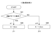
- the first cutting condition ⁇ 1 is satisfied if the workpiece 260 is guided in the Z direction by sliding.
- the amplitude A is set to 0 mm, that is, relative vibration is not superimposed on the relative movement of both 220 and 260.
- the basic cutting condition ⁇ 0 is satisfied if the first cutting condition ⁇ 1 does not apply.
- the amplitude A is set to 1.3 mm.
- S81 it is determined whether or not the Z-direction guidance of the workpiece 260 is sliding guidance. If the determination is affirmative, it is determined that the first cutting condition ⁇ 1 is satisfied, and the process proceeds to S88, where the first vibration condition ⁇ 1 is adopted and the amplitude A is set to 0 mm. On the other hand, if a negative determination is made in S81, it is determined that the basic cutting condition ⁇ 0 is satisfied, and the process proceeds to S89, where the basic vibration condition ⁇ 0 is adopted and the amplitude A is set to 1.3 mm.
- the first cutting condition ⁇ 1 is satisfied when the inertia in relative Z-axis rotation is 1.1 kg ⁇ m 2 or more. According to the first vibration condition ⁇ 1 corresponding to this, the amplitude A is set to 1.1 mm.
- the basic cutting condition ⁇ 0 is satisfied if the first cutting condition ⁇ 1 does not apply. According to the basic vibration condition ⁇ 0 corresponding to this, the amplitude A is set to 1.3 mm.
- This specific example can be suitably adopted, for example, when the inertia is 1.1 kg ⁇ m 2 or more and chips can be sufficiently separated even if the amplitude A is reduced.
- the first cutting condition ⁇ 1 is satisfied when the workpiece 260 is vibrated when performing relative vibration between the two 220 and 260.
- the amplitude A is set to 0.9 mm.
- the basic cutting condition ⁇ 0 is satisfied if the first cutting condition ⁇ 1 does not apply.
- the amplitude A is set to 1.5 mm.
- S101 it is determined whether or not the workpiece 260 is to be vibrated. If the determination is affirmative, it is determined that the first cutting condition ⁇ 1 is satisfied, and the process proceeds to S108, where the first vibration condition ⁇ 1 is adopted and the amplitude A is set to 0.9 mm. On the other hand, if a negative determination is made in S101, it is determined that the basic cutting condition ⁇ 0 is satisfied, and the process proceeds to S109, where the basic vibration condition ⁇ 0 is adopted and the amplitude A is set to 1.5 mm.
- the second cutting condition ⁇ 2 is satisfied when the direction of relative X-axis movement is on the plus side in the X direction.
- the amplitude A is set to 1.6 mm and the frequency f is set to 195 Hz.
- the first cutting condition ⁇ 1 is satisfied when the direction of the relative Z-axis movement is on the negative side of the Z direction when the second cutting condition ⁇ 2 does not apply.
- the amplitude A is set to 1.5 mm and the frequency f is set to 230 Hz.
- the basic cutting condition ⁇ 0 is satisfied if neither the second cutting condition ⁇ 2 nor the first cutting condition ⁇ 1 applies.
- the amplitude A is set to 1.2 mm and the frequency f is set to 230 Hz.
- S111 it is determined whether the direction of relative X-axis movement is on the plus side in the X direction. If the determination is affirmative, it is determined that the second cutting condition ⁇ 2 is satisfied, and the process proceeds to S117, where the second vibration condition ⁇ 2 is adopted, the amplitude A is set to 1.6 mm, and the frequency f is set to 195. On the other hand, if a negative determination is made in S111, the process proceeds to S112, where it is determined whether the direction of relative Z-axis movement is on the negative side of the Z direction.
- first to eleventh specific examples shown above can also be implemented in combination with each other. Specifically, for example, if the first specific example shown in FIG. 5 is combined with the fifth specific example shown in FIG.
- the frequency f can be set based on the type of.
- FIG. 16 shows a case where, in a comparative example without the acquisition unit 10 and the selection unit 20, the same thing as the eleventh specific example described above is performed by changing the vibration condition ⁇ using the program command Co.
- the right side in FIG. 16 shows the program command Co when the above-described eleventh example is implemented in this embodiment. More specifically, here, the vibration condition ⁇ is switched in the order of basic vibration condition ⁇ 0 ⁇ first vibration condition ⁇ 1 ⁇ basic vibration condition ⁇ 0 ⁇ second vibration condition ⁇ 2 ⁇ basic vibration condition ⁇ 0.
- the selection unit 20 recognizes the cutting condition ⁇ in the cutting operation to be performed, and selects the vibration condition ⁇ based on the recognized cutting condition ⁇ and the correspondence information ⁇ . Therefore, the machine tool control device 100 can superimpose relative vibrations on the relative movement of both 220 and 260 without excess or deficiency based on the selected vibration condition ⁇ . This makes it possible to reduce wasteful operations due to relative vibration as much as possible, and to reduce damage to the cutting tool 220, workpiece 260, machine tool 200, etc. due to relative vibration as much as possible. Moreover, even if the user does not input a command to change the vibration condition ⁇ in the program command Co, the selection unit 20 automatically selects the vibration condition ⁇ corresponding to the cutting condition ⁇ , so that the effort on the part of the user can be reduced.
- the acquisition unit 10 includes a storage unit 15 that stores the acquired correspondence information ⁇ . Therefore, even when it is not possible to appropriately acquire the correspondence information ⁇ through a network or the like, the selection unit 20 can select the vibration condition ⁇ based on the correspondence information ⁇ stored in the storage unit 15 without any problem. can.
- the selection unit 20 recognizes the cutting condition ⁇ of the cutting operation to be executed based on the program command Co input by the user. Therefore, the cutting condition ⁇ can be efficiently recognized using the program command Co.
- FIG. 17 is a table showing correspondence information ⁇ in this embodiment.
- the cutting conditions ⁇ include the type of cutting tool 220 and general cutting conditions.
- the type of cutting tool 220 is recognized based on the identification information of cutting tool 220. Specifically, when "111" is input for the cutting tool 220 in the program command Co, the selection unit 20 recognizes that the cutting tool 220 is the first tool, and in the program command Co, the selection unit 20 recognizes that the cutting tool 220 is the first tool. When “112" is input for 220, the selection unit 20 recognizes that the cutting tool 220 is the second tool. Similarly, when “113", “114", etc. are input, they are recognized as “third tool", "fourth tool”, etc.
- General cutting conditions are set separately for each type of cutting tool 220.
- the general cutting conditions when the cutting tool 220 is the first tool include a basic cutting condition ⁇ 0, a first cutting condition ⁇ 1, and a second cutting condition ⁇ 2.
- the first cutting condition ⁇ 1 here is satisfied when the direction of the relative Z-axis movement is on the positive Z-direction side.
- the amplitude A is set to 1.60 mm and the frequency f is set to 195 Hz.
- the second cutting condition ⁇ 2 is satisfied when the direction of the relative X-axis movement is on the plus side in the X direction when the first cutting condition ⁇ 1 does not apply.
- the amplitude A is set to 1.50 mm and the frequency f is set to 195 Hz.
- the basic cutting condition ⁇ 0 is satisfied if neither the first cutting condition ⁇ 1 nor the second cutting condition ⁇ 2 applies.
- the amplitude A is set to 1.25 mm and the frequency f is set to 225 Hz.
- the general cutting conditions when the cutting tool 220 is the second tool are, for example, basic correspondence information ⁇ 0 that is different from when the cutting tool 220 is the first tool, and different from when the cutting tool 220 is the first tool.
- the first cutting condition ⁇ 1 here is satisfied when the direction of relative X-axis movement is on the plus side in the X direction. According to the first vibration condition ⁇ 1 corresponding to this, relative vibration is not performed.
- the basic cutting condition ⁇ 0 is satisfied if the first cutting condition ⁇ 1 does not apply.
- the amplitude A is set to 1.20 mm and the frequency f is set to 230 Hz.
- the correspondence information ⁇ shown above may be obtained from, for example, a network, or may be created independently by the user. As a specific example of the latter case, for example, a case where the machine tool control device 100 displays a table shown in FIG. 17 on the display and the user inputs a desired numerical value into each cell of the table will be exemplified.
- S211 it is determined whether the identification information of the cutting tool 220 is "111". If the determination is affirmative, it is determined that the cutting tool 220 is the first tool, and the process proceeds to S212, where it is determined whether the direction of relative Z-axis movement is on the positive side of the Z direction. If the determination is affirmative, it is determined that the first cutting condition ⁇ 1 for the first tool is satisfied, and the process proceeds to S217, where the first vibration condition ⁇ 1 for the first tool is adopted, the amplitude A is set to 1.60 mm, and the frequency is Set f to 195Hz.
- step S213 it is determined that the basic cutting condition ⁇ 0 for the first tool is satisfied, and the process proceeds to S219, where the basic vibration condition ⁇ 0 is adopted, the amplitude A is set to 1.25 mm, and the frequency f is set to 225 Hz. Set.
- step S211 it is determined that the cutting tool 220 is not the first tool, and the process proceeds to step S221.
- S221 it is determined whether the identification information is "112". If an affirmative determination is made, it is determined that the cutting tool is the second tool, and the process proceeds to S212, where it is determined whether the direction of relative X-axis movement is on the negative side of the X direction. If the determination is affirmative, it is determined that the first cutting condition ⁇ 1 for the second tool is satisfied, and the process proceeds to S228, where the first vibration condition ⁇ 1 for the second tool is adopted, and relative vibration is not superimposed.
- step S222 it is assumed that the basic cutting condition ⁇ 0 for the second tool is satisfied, and the process proceeds to S229, where the basic vibration condition ⁇ 0 for the second tool is adopted and the amplitude A is set to 1.20 mm. And the frequency f is set to 230Hz.
- step S221 it is determined that the cutting tool 220 is not the second tool, and the process proceeds to step S231.
- the selection unit 20 recognizes the type of the cutting tool 220 based on a command instructing the cutting tool 220 in the program command Co, specifically, based on identification information such as "111", "112", etc. Thereafter, the selection unit 20 recognizes the general cutting conditions based on the subsequent program command Co, and selects the vibration condition ⁇ based on the recognized general cutting conditions.
- the selection unit 20 recognizes the type of the cutting tool 220 based on the identification information of the cutting tool 220. Therefore, the type of cutting tool 220 can be easily and efficiently recognized.
- the cutting conditions ⁇ include the type of cutting tool 220 and general cutting conditions set for each type of cutting tool 220. Therefore, the selection unit 20 can first sort the cutting tools 220 based on the type, and then select the specific vibration conditions ⁇ based on the general cutting conditions. Thereby, the optimum vibration condition ⁇ can be efficiently selected.
- the embodiment shown above can be modified as follows, for example. If the correspondence information ⁇ can be obtained at any time via a network or the like, the storage unit 15 may be omitted and the necessary correspondence information ⁇ may be appropriately acquired from the network as needed.
- the storage unit 15 may be removed from the computer Cp and provided in the cloud or the like. Instead of configuring the machine tool control device 100 mainly by the computer Cp and the machine tool control program 100p, a dedicated machine tool control device 100 may be provided.
Landscapes
- Engineering & Computer Science (AREA)
- Mechanical Engineering (AREA)
- Physics & Mathematics (AREA)
- Geometry (AREA)
- Human Computer Interaction (AREA)
- Manufacturing & Machinery (AREA)
- General Physics & Mathematics (AREA)
- Automation & Control Theory (AREA)
- Turning (AREA)
Priority Applications (5)
| Application Number | Priority Date | Filing Date | Title |
|---|---|---|---|
| DE112022007024.2T DE112022007024T5 (de) | 2022-07-13 | 2022-07-13 | Steuerungsvorrichtung für Arbeitsmaschinen und Steuerungsprogramm für Arbeitsmaschinen |
| JP2024533386A JPWO2024013870A1 (https=) | 2022-07-13 | 2022-07-13 | |
| US18/866,348 US20250326080A1 (en) | 2022-07-13 | 2022-07-13 | Machine tool control device and non-transitory computer-readable storage medium |
| PCT/JP2022/027518 WO2024013870A1 (ja) | 2022-07-13 | 2022-07-13 | 工作機械制御装置および工作機械制御プログラム |
| CN202280097851.5A CN119546404A (zh) | 2022-07-13 | 2022-07-13 | 机床控制装置以及机床控制程序 |
Applications Claiming Priority (1)
| Application Number | Priority Date | Filing Date | Title |
|---|---|---|---|
| PCT/JP2022/027518 WO2024013870A1 (ja) | 2022-07-13 | 2022-07-13 | 工作機械制御装置および工作機械制御プログラム |
Publications (1)
| Publication Number | Publication Date |
|---|---|
| WO2024013870A1 true WO2024013870A1 (ja) | 2024-01-18 |
Family
ID=89536137
Family Applications (1)
| Application Number | Title | Priority Date | Filing Date |
|---|---|---|---|
| PCT/JP2022/027518 Ceased WO2024013870A1 (ja) | 2022-07-13 | 2022-07-13 | 工作機械制御装置および工作機械制御プログラム |
Country Status (5)
| Country | Link |
|---|---|
| US (1) | US20250326080A1 (https=) |
| JP (1) | JPWO2024013870A1 (https=) |
| CN (1) | CN119546404A (https=) |
| DE (1) | DE112022007024T5 (https=) |
| WO (1) | WO2024013870A1 (https=) |
Citations (4)
| Publication number | Priority date | Publication date | Assignee | Title |
|---|---|---|---|---|
| WO2018117203A1 (ja) * | 2016-12-22 | 2018-06-28 | シチズン時計株式会社 | 工作機械およびその制御装置 |
| JP6530780B2 (ja) * | 2017-05-16 | 2019-06-12 | ファナック株式会社 | 揺動切削のための表示装置および加工システム |
| JP6912506B2 (ja) * | 2019-03-06 | 2021-08-04 | ファナック株式会社 | 工作機械の制御装置 |
| WO2021167014A1 (ja) * | 2020-02-20 | 2021-08-26 | ファナック株式会社 | 工作機械の制御装置 |
Family Cites Families (1)
| Publication number | Priority date | Publication date | Assignee | Title |
|---|---|---|---|---|
| JPS5033929U (https=) | 1973-07-23 | 1975-04-11 |
-
2022
- 2022-07-13 JP JP2024533386A patent/JPWO2024013870A1/ja active Pending
- 2022-07-13 CN CN202280097851.5A patent/CN119546404A/zh active Pending
- 2022-07-13 WO PCT/JP2022/027518 patent/WO2024013870A1/ja not_active Ceased
- 2022-07-13 DE DE112022007024.2T patent/DE112022007024T5/de active Pending
- 2022-07-13 US US18/866,348 patent/US20250326080A1/en active Pending
Patent Citations (4)
| Publication number | Priority date | Publication date | Assignee | Title |
|---|---|---|---|---|
| WO2018117203A1 (ja) * | 2016-12-22 | 2018-06-28 | シチズン時計株式会社 | 工作機械およびその制御装置 |
| JP6530780B2 (ja) * | 2017-05-16 | 2019-06-12 | ファナック株式会社 | 揺動切削のための表示装置および加工システム |
| JP6912506B2 (ja) * | 2019-03-06 | 2021-08-04 | ファナック株式会社 | 工作機械の制御装置 |
| WO2021167014A1 (ja) * | 2020-02-20 | 2021-08-26 | ファナック株式会社 | 工作機械の制御装置 |
Also Published As
| Publication number | Publication date |
|---|---|
| DE112022007024T5 (de) | 2025-02-20 |
| CN119546404A (zh) | 2025-02-28 |
| JPWO2024013870A1 (https=) | 2024-01-18 |
| US20250326080A1 (en) | 2025-10-23 |
Similar Documents
| Publication | Publication Date | Title |
|---|---|---|
| US8240234B2 (en) | Methods and systems for chip breaking in turning applications using CNC toolpaths | |
| JP5594685B2 (ja) | 工具軌跡生成装置、工具軌跡算出方法および工具軌跡生成プログラム | |
| CN105843172B (zh) | 具有自动地变更切削条件的功能的机床 | |
| US6428252B1 (en) | Method for machining | |
| JP6133995B2 (ja) | 工具経路評価方法、工具経路生成方法、及び工具経路生成装置 | |
| JP5900907B2 (ja) | 工具軌跡生成装置、工具軌跡生成方法および工具軌跡生成プログラム | |
| JP4835442B2 (ja) | 回転工具を用いた肩削り加工における切削加工終了座標の算出方法 | |
| US12491595B2 (en) | Machine tool control device | |
| JP2021092936A (ja) | 加工装置、加工方法および切削工具 | |
| CN104227496A (zh) | 旋转切削工具的初始轴方向切削深度设定方法和控制装置 | |
| CN104768684B (zh) | 机床的控制装置及机床 | |
| JP7645761B2 (ja) | ワークの旋削加工方法及び工作機械、加工プログラム | |
| JP5886656B2 (ja) | 数値制御装置 | |
| CN105492980B (zh) | 刀具路径生成方法及刀具路径生成装置 | |
| WO2018011990A1 (ja) | 加工プログラム生成装置及び加工方法 | |
| US20240131648A1 (en) | Machine tool control device | |
| WO2024013870A1 (ja) | 工作機械制御装置および工作機械制御プログラム | |
| JP6972404B1 (ja) | プログラム、clデータ編集装置及び工作機械 | |
| JP5891021B2 (ja) | レーザ加工方法、自動プログラミング装置および加工システム | |
| JP5909355B2 (ja) | レーザ加工機の自動プログラミング装置及びその方法およびレーザ加工システム | |
| JP2005040912A (ja) | 加工装置 | |
| JPH11151606A (ja) | 輪郭加工方法および加工機械 | |
| US20160209824A1 (en) | Numerical controller controlling machining tool based on skiving instruction | |
| JP4161177B2 (ja) | 切断加工方法と切断加工システム | |
| JP2023141865A (ja) | 工作機械 |
Legal Events
| Date | Code | Title | Description |
|---|---|---|---|
| 121 | Ep: the epo has been informed by wipo that ep was designated in this application |
Ref document number: 22951084 Country of ref document: EP Kind code of ref document: A1 |
|
| WWE | Wipo information: entry into national phase |
Ref document number: 2024533386 Country of ref document: JP |
|
| WWE | Wipo information: entry into national phase |
Ref document number: 18866348 Country of ref document: US |
|
| WWE | Wipo information: entry into national phase |
Ref document number: 112022007024 Country of ref document: DE |
|
| WWE | Wipo information: entry into national phase |
Ref document number: 202280097851.5 Country of ref document: CN |
|
| WWP | Wipo information: published in national office |
Ref document number: 112022007024 Country of ref document: DE |
|
| WWP | Wipo information: published in national office |
Ref document number: 202280097851.5 Country of ref document: CN |
|
| 122 | Ep: pct application non-entry in european phase |
Ref document number: 22951084 Country of ref document: EP Kind code of ref document: A1 |
|
| WWP | Wipo information: published in national office |
Ref document number: 18866348 Country of ref document: US |