WO2024010089A1 - 光学モジュール、光学装置、および光学モジュールの製造方法 - Google Patents
光学モジュール、光学装置、および光学モジュールの製造方法 Download PDFInfo
- Publication number
- WO2024010089A1 WO2024010089A1 PCT/JP2023/025318 JP2023025318W WO2024010089A1 WO 2024010089 A1 WO2024010089 A1 WO 2024010089A1 JP 2023025318 W JP2023025318 W JP 2023025318W WO 2024010089 A1 WO2024010089 A1 WO 2024010089A1
- Authority
- WO
- WIPO (PCT)
- Prior art keywords
- optical system
- optical
- lens group
- light
- branching
- Prior art date
- Legal status (The legal status is an assumption and is not a legal conclusion. Google has not performed a legal analysis and makes no representation as to the accuracy of the status listed.)
- Ceased
Links
Images


Classifications
-
- G—PHYSICS
- G02—OPTICS
- G02B—OPTICAL ELEMENTS, SYSTEMS OR APPARATUS
- G02B13/00—Optical objectives specially designed for the purposes specified below
-
- G—PHYSICS
- G02—OPTICS
- G02B—OPTICAL ELEMENTS, SYSTEMS OR APPARATUS
- G02B5/00—Optical elements other than lenses
-
- G—PHYSICS
- G03—PHOTOGRAPHY; CINEMATOGRAPHY; ANALOGOUS TECHNIQUES USING WAVES OTHER THAN OPTICAL WAVES; ELECTROGRAPHY; HOLOGRAPHY
- G03B—APPARATUS OR ARRANGEMENTS FOR TAKING PHOTOGRAPHS OR FOR PROJECTING OR VIEWING THEM; APPARATUS OR ARRANGEMENTS EMPLOYING ANALOGOUS TECHNIQUES USING WAVES OTHER THAN OPTICAL WAVES; ACCESSORIES THEREFOR
- G03B13/00—Viewfinders; Focusing aids for cameras; Means for focusing for cameras; Autofocus systems for cameras
- G03B13/02—Viewfinders
- G03B13/10—Viewfinders adjusting viewfinders field
- G03B13/14—Viewfinders adjusting viewfinders field to compensate for parallax due to short range
Definitions
- the present disclosure relates to an optical module, an optical device, and a method for manufacturing an optical module.
- An optical module has been proposed that includes a second sensor having different values (for example, see Patent Document 1).
- the optical module of the present disclosure has a branching surface that transmits a part of the incident light and reflects at least a part different from the part of the incident light, and the light that is transmitted by the branching surface and the light that is reflected by the branching surface.
- the optical module is an optical module that forms images of light that is transmitted through the front lens group, an optical path branching member that has a branching surface, and a branching surface that has a positive refractive power and enters in order from the object side.
- a first optical system including a first rear lens group, a front lens group, an optical path branching member, and a second rear lens group having a positive refractive power and into which light reflected by the branching surface is incident, in order from the object side.
- a second optical system including a side lens group, and one of the first optical system and the second optical system includes an aperture stop on the branching surface or on the image plane side of the branching surface.
- the optical module of the present disclosure has a branching surface that transmits a part of the incident light and reflects at least a part different from the part of the incident light, and the light that is transmitted by the branching surface and the light that is reflected by the branching surface.
- the optical module is an optical module that forms an image of light that is transmitted from the front lens group, an optical path branching member that includes a branching surface, and a branching surface that has a positive refractive power and enters in order from the object side.
- a first optical system including a first rear lens group, a front lens group, an optical path branching member, and a second rear lens group having positive refractive power and into which light reflected by the branching surface is incident, in order from the object side.
- a second optical system including a side lens group, and the number of lenses included in the front lens group is greater than the number of lenses included in one of the first rear lens group and the second rear lens group.
- the optical module of the present disclosure has a branching surface that transmits a part of the incident light and reflects at least a part different from the part of the incident light, and the light that is transmitted by the branching surface and the light that is reflected by the branching surface.
- the optical module is an optical module that forms an image of light that is transmitted from the front lens group, an optical path branching member that includes a branching surface, and a branching surface that has a positive refractive power and enters in order from the object side.
- a first optical system including a first rear lens group, a front lens group, an optical path branching member, and a second rear lens group having positive refractive power and into which light reflected by the branching surface is incident, in order from the object side.
- a second optical system including a side lens group, and satisfies the following conditional expression. 0.10 ⁇ Df/TL1 ⁇ 0.50
- Df Length on the optical axis from the lens surface closest to the object side of the front lens group to the lens surface closest to the image plane of the front lens group
- TL1 Lens surface closest to the object side of the front lens group in the first optical system Length on the optical axis from to the image plane
- the optical module of the present disclosure has a branching surface that transmits a part of the incident light and reflects at least a part different from the part of the incident light, and the light that is transmitted by the branching surface and the light that is reflected by the branching surface.
- the optical module is an optical module that forms an image of light that is transmitted from the front lens group, an optical path branching member that includes a branching surface, and a branching surface that has a positive refractive power and enters in order from the object side.
- a first optical system including a first rear lens group, a front lens group, an optical path branching member, and a second rear lens group having positive refractive power and into which light reflected by the branching surface is incident, in order from the object side.
- a second optical system including a side lens group, the front lens group having negative refractive power.
- the method for manufacturing an optical module of the present disclosure includes a branching surface that transmits a portion of incident light and reflects at least a portion of the incident light that is different from the portion of the incident light, and the light transmitted by the branching surface and the branching surface are separated.
- a method for manufacturing an optical module that forms images of light reflected by a surface comprising: in order from the object side, a front lens group, an optical path branching member having a branching surface, and a branching surface having a positive refractive power;
- the first optical system is arranged to include a first rear lens group into which the transmitted light is incident, and in order from the object side, a front lens group, an optical path branching member, and a branching surface having a positive refractive power.
- the second optical system is arranged so as to include a second rear lens group into which the reflected light is incident, and an aperture stop is provided on the branching surface or on the image plane side of the branching surface in one of the first optical system and the second optical system.
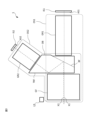
- FIG. 1 is a schematic diagram illustrating a schematic configuration of an optical module according to the present embodiment.
- FIG. 3 is a cross-sectional view of the first optical system included in the optical module of the first example.
- FIG. 3 is a diagram showing various aberrations of the first optical system included in the optical module of the first example.
- FIG. 3 is a cross-sectional view of a second optical system included in the optical module of the first embodiment.
- FIG. 7 is a diagram showing various aberrations of the second optical system included in the optical module of the first example.
- FIG. 7 is a cross-sectional view of the first optical system included in the optical module of the second embodiment.
- FIG. 7 is a diagram of various aberrations of the first optical system included in the optical module of the second example.
- FIG. 7 is a cross-sectional view of a second optical system included in the optical module of the second embodiment.
- FIG. 7 is a diagram showing various aberrations of the second optical system included in the optical module of the second example.
- FIG. 7 is a cross-sectional view of the first optical system included in the optical module of the third example.
- FIG. 7 is a diagram of various aberrations of the first optical system included in the optical module of the third example.
- FIG. 7 is a cross-sectional view of a second optical system included in the optical module of the third embodiment.
- FIG. 7 is a diagram showing various aberrations of the second optical system included in the optical module of the third example.
- FIG. 1 is a schematic diagram of an optical device including an optical module of this embodiment.
- FIG. 2 is a functional block diagram of a processor included in the information processing device included in the optical device of the present embodiment.
- 1 is a flowchart showing an outline of a method for manufacturing an optical module according to the present embodiment.
- FIG. 1 is a schematic diagram illustrating the schematic configuration of the optical module of this embodiment.
- the optical module 1 of this embodiment in order from the object side, enters the front lens group GF, the optical path branching member OB having the branching surface BF, the front lens group GF and the optical path branching member OB, and is transmitted through the branching surface BF. It has a first optical system OS1 including a first rear lens group GR1 into which light enters. Further, in the optical module 1 of the present embodiment, in order from the object side, light enters the front lens group GF, the optical path branching member OB, the front lens group GF and the optical path branching member OB, and is reflected by the branching surface BF. It has a second optical system OS2 including a second rear lens group GR2.
- the first optical axis X1 of the first optical system OS1 and the second optical axis X2 of the second optical system OS2 are shown on the object side with respect to the branch plane BF so as not to overlap each other for the sake of explanation. .
- the light emitted from the front lens group GF enters the optical path branching member OB.
- the optical path branching member OB is a dichroic prism having a branching surface BF that transmits either visible light or near-infrared light and reflects the other. Visible light includes, for example, d-line (wavelength: 587.6 nm) or g-line (wavelength: 435.8 nm), and near-infrared light includes, for example, s-line (wavelength: 852.1 nm).
- the optical module 1 of this embodiment branches the light incident from the front lens group GF using the optical path branching member OB.
- the optical path branching member OB may be a dichroic mirror having a branching surface BF.
- the optical module 1 of the present embodiment includes a first imaging section IS1 including a first light receiving surface AS1 on which an imaging device composed of a CCD, CMOS, or the like is arranged.
- the first optical system OS1 of the present embodiment transmits light (one of visible light and near-infrared light) emitted from the front lens group GF and transmitted through the branching surface BF of the optical path branching member OB to the first optical system OS1.
- An image is formed on the first light receiving surface AS1 of the first imaging section IS1 by the side lens group GR1.
- the first imaging unit IS1 outputs data corresponding to the light imaged on the first light receiving surface AS1.
- the optical module 1 of this embodiment has a second imaging section IS2 including a second light-receiving surface AS2 on which an imaging element composed of a CCD, CMOS, or the like is arranged.
- the second optical system OS2 of the present embodiment includes light (visible light and near-infrared The other of the lights) is imaged on the second light receiving surface AS2 of the second imaging section IS2 by the second rear lens group GR2.
- the second imaging unit IS2 outputs data corresponding to the light imaged on the second light receiving surface AS2.
- the optical module 1 of this embodiment appropriately controls the light transmitted by the branching surface BF and the light reflected by the branching surface BF out of the incident light by the first optical system OS1 and the second optical system OS2. It can be imaged.
- the imaging unit that forms an image of visible light has an imaging element that receives a plurality of colors including, for example, d-line or g-line, and represents the external appearance of the object.
- a color image may also be output. The generated image may be used to detect the appearance of the object.
- the optical module 1 of this embodiment may include a light source LS that emits light of a predetermined wavelength such as near-infrared light (for example, S-line).
- the light source LS is an example of a lighting section, and includes a laser or the like as a light emitting element.
- the optical module 1 of this embodiment irradiates a target object (not shown) with light of a predetermined wavelength using a light source LS.
- light from an object enters the front lens group GF.
- the imaging unit that forms an image of near-infrared light can receive the light emitted from the light source LS and reflected by the object.
- Data output by the imaging section that forms an image of near-infrared light among the first imaging section IS1 and the second imaging section IS2 may be used to detect the distance to the object.
- data output by an imaging unit that forms an image of near-infrared light can be used to detect the time it takes for the light emitted from the light source LS to be reflected by an object and received by the imaging unit.
- the detected time may be used to detect the distance to the object using the TOF (Time of Flight) method.
- TOF Time of Flight
- the light emitted from the light source LS may have a predetermined pattern such as a stripe or a lattice.
- the imaging unit on which the near-infrared light is imaged outputs data representing the distortion of the pattern of light reflected by the object.
- Data output by the imaging unit that forms an image of near-infrared light may be used to detect the distance to an object using a structured light method.
- the optical module 1 of this embodiment includes a light source LS that emits light used for detecting the distance to the object, and irradiates the target object with the light used for detecting the distance to the object.
- the structured light method allows for good distance detection of objects.
- the optical module 1 of this embodiment can detect both the appearance of a target object and the distance to the object.
- each pixel in the image of the object and the image of the object corresponding to the pixel are The calculation process for associating the distance to the surface is reduced.
- the optical system used to detect the distance to the object preferably has a relatively small F value and can obtain a relatively bright image.
- an optical system used to detect the appearance of an object it is preferable for an optical system used to detect the appearance of an object to achieve high optical performance and to be able to obtain an image in which various aberrations are appropriately corrected. It is more preferable for an optical system used to detect the appearance of an object to have a relatively small F value and to be able to obtain a relatively bright image.
- the F value of the optical system used for detecting the object distance among the first optical system OS1 and the second optical system OS2 is It may be configured such that the F value is equal to or less than the F value of the optical system used for detecting the appearance of the object.
- the optical module 1 of the present embodiment can use a brighter image for detecting the distance to the object, and can appropriately correct various aberrations for detecting the appearance of the object. Images can be used.
- the optical module 1 of this embodiment satisfies both of the following conditional expressions. (4) 0.20 ⁇ Fno_tof/Fno_img ⁇ 1.00 (5) 1.00 ⁇ Fno_tof ⁇ 2.00 however, Fno_tof: F value of the optical system used for detecting the distance to the object among the first optical system OS1 and second optical system OS2 Fno_img: F value of the optical system used for detecting the appearance of the object among the first optical system OS1 and the second optical system OS2 F number of optical system used
- Conditional expression (4) is based on the F value of the optical system used for detecting the distance to the object among the first optical system OS1 and the second optical system OS2, and the F value of the optical system used for detecting the distance to the object among the first optical system OS1 and the second optical system OS2. This defines the ratio to the F value of the optical system used for detecting appearance.
- the optical module 1 of this embodiment can ensure appropriate brightness in each of the first optical system OS1 and the second optical system OS2 by satisfying conditional expression (4).
- conditional expression (4) exceeds the upper limit in the optical module 1 of this embodiment, the appropriate brightness will be It is not possible to ensure that
- the effects of this embodiment can be made more reliable.
- conditional expression (4) in the optical module 1 of the present embodiment falls below the lower limit, the optical system used for detecting the appearance of the object among the first optical system OS1 and the second optical system OS2 Unable to ensure brightness.
- the effects of this embodiment can be made more reliable. Further, in order to further ensure the effects of this embodiment, it is preferable to set the lower limit value of conditional expression (4) to 0.30, 0.40, and further 0.55.
- Conditional expression (5) defines the F value of the optical system used for detecting the distance to the object among the first optical system OS1 and the second optical system OS2.
- conditional expression (5) exceeds the upper limit in the optical module 1 of this embodiment, the appropriate brightness will be It is not possible to ensure that
- the effects of this embodiment can be made more reliable. Further, in order to ensure the effects of this embodiment, it is preferable to set the upper limit of conditional expression (5) to 1.80, 1.60, and further 1.40.
- conditional expression (5) in the optical module 1 of the present embodiment falls below the lower limit, the optical system used for detecting the distance to the object among the first optical system OS1 and the second optical system OS2 becomes larger. Too much.
- the effects of this embodiment can be made more reliable. Further, in order to further ensure the effects of this embodiment, it is preferable to set the lower limit value of conditional expression (5) to 1.10, 1.15, and further 1.20.
- the optical system used for detecting the appearance of an object among the first optical system OS1 and the second optical system OS2 has a cemented lens, and the first optical system OS1 and the second optical system It is preferable that the optical system in the system OS2 used for detecting the distance between the image and the object consists of only a single lens.
- the optical system whose image is used for detecting the appearance of an object among the first optical system OS1 and the second optical system OS2 has a cemented lens, so that the optical system is used for detecting the appearance of the object. Image chromatic aberration can be appropriately corrected.
- the optical system used for detecting the distance from the image to the object among the first optical system OS1 and the second optical system OS2 is configured with only a single lens. can be downsized.
- an image used for detecting the distance to the object and an image used for detecting the appearance of the object are used. It is preferable to reduce the area represented in only one of the images.
- the optical module 1 of this embodiment satisfies the following conditional expression. (7) 0.83 ⁇ ⁇ 1/ ⁇ 2 ⁇ 1.20 however, ⁇ 1: Full angle of view of the first optical system OS1 ⁇ 2: Full angle of view of the second optical system OS2
- Conditional expression (7) defines the ratio between the total angle of view of the first optical system OS1 and the total angle of view of the second optical system OS2.
- the optical module 1 of this embodiment when the value of conditional expression (7) exceeds the upper limit, the area is represented only in one of the image used for detecting the appearance of the object and the image used for detecting the distance to the object. becomes too large.
- the effects of this embodiment can be made more reliable. Furthermore, in order to further ensure the effects of this embodiment, it is preferable to set the upper limit of conditional expression (7) to 1.15, 1.10, and further 1.05.
- conditional expression (7) falls below the lower limit, the image is displayed only in one of the image used for detecting the appearance of the object and the image used for detecting the distance to the object. area becomes too large.
- the effects of this embodiment can be made more reliable. Further, in order to further ensure the effects of this embodiment, it is preferable to set the lower limit value of conditional expression (7) to 0.87, 0.91, and further 0.95.
- the optical module 1 of this embodiment satisfies the following conditional expression. (8) 70.0° ⁇ ⁇ 1 however, ⁇ 1: Full angle of view of the first optical system OS1
- Conditional expression (8) defines the entire angle of view of the first optical system OS1.
- the optical module 1 of this embodiment can obtain an image representing a wide range using the first optical system OS1 by satisfying conditional expression (8).
- the optical module 1 of this embodiment if the value of conditional expression (8) is less than the lower limit, the range represented by the image obtained by the first optical system OS1 becomes too narrow.
- the effects of this embodiment can be made more reliable. Further, in order to further ensure the effects of this embodiment, it is preferable to set the lower limit value of conditional expression (8) to 75.0°, 80.0°, and further to 90.0°.
- the first optical system OS1 may be used to detect the appearance of an object
- the second optical system OS2 may be used to detect the distance to the object.
- the first optical system OS1 into which the light transmitted by the branching surface BF enters, is not affected by deterioration due to reflection of a light beam caused by the surface precision of the branching surface BF. , an image with less deterioration can be used to detect the appearance of an object.
- one of the first optical system OS1 and the second optical system OS2 includes an aperture stop on the branching surface or on the image plane side of the branching surface.
- the first optical system OS1 and the second optical system OS2 may include an aperture stop on the branching surface BF or on the image plane side of the branching surface BF.
- the optical module 1 of this embodiment By providing the optical module 1 of this embodiment with an aperture stop, it is possible to obtain the first optical system OS1 or the second optical system OS2 having appropriate optical performance.
- the aperture stop at the branching surface BF or closer to the image plane than the branching surface BF, the peripheral luminous flux of the light incident on the branching surface BF is not restricted, and the peripheral luminous flux is attenuated relative to the central luminous flux. can be reduced.
- an aperture stop is provided on the image plane side of at least one lens component disposed on the image plane side of the optical path branching member OB.
- the number of lenses included in the front lens group GF is smaller than the number of lenses included in one of the first rear lens group GR1 and the second rear lens group GR2.
- the number of lenses included in the front lens group GF is smaller than the number of lenses included in one of the first rear lens group GR1 and the second rear lens group GR2.
- the optical module 1 can be downsized, and the first optical system OS1 or the second optical system OS2 having appropriate optical performance can be obtained.
- the number of lenses included in the front lens group GF is greater than the number of lenses included in the other of the first rear lens group GR1 and the second rear lens group GR2 (the first rear lens group GR1 and the second rear lens group GR2).
- the number of lenses in the second rear lens group GR2 may be smaller than the number of lenses included in the above-mentioned one or the other, which is smaller than the number of lenses in the front lens group GF.
- the number of lenses included in the front lens group GF is smaller than the number of lenses included in the other of the first rear lens group GR1 and the second rear lens group GR2.
- the optical module 1 can be downsized, and the first optical system OS1 and the second optical system OS2 having appropriate optical performance can be obtained.
- the optical module 1 of this embodiment satisfies the following conditional expression. (2) 0.10 ⁇ Df/TL1 ⁇ 0.50
- Df Length on the optical axis from the lens surface closest to the object side of the front lens group GF to the lens surface closest to the image plane side of the front lens group GF
- TL1 The distance closest to the object side of the front lens group GF in the first optical system OS1 Length on the optical axis from the side lens surface to the image plane
- Conditional expression (2) is based on the length on the optical axis from the lens surface closest to the object side of the front lens group GF to the lens surface closest to the image plane of the front lens group, and the length of the front lens group GF in the first optical system OS1. Defines the ratio of the length on the optical axis from the lens surface closest to the object side to the image plane.
- conditional expression (2) it is possible to miniaturize the optical module 1 and perform optical design suitable for each of the lights branched by the branching surface BF.
- conditional expression (2) if the value of conditional expression (2) exceeds the upper limit, it becomes difficult to perform optical design suitable for each of the branched lights.
- the effects of this embodiment can be made more reliable. Further, in order to further ensure the effects of this embodiment, it is preferable to set the upper limit of conditional expression (2) to 0.40, 0.37, and further 0.33.
- the optical module 1 of this embodiment if the value of conditional expression (2) falls below the lower limit, the number of lenses required for optical design suitable for each of the branched lights increases, and the optical module 1 becomes larger.
- the effects of this embodiment can be made more reliable. Further, in order to further ensure the effects of this embodiment, it is preferable to set the lower limit value of conditional expression (2) to 0.15, 0.17, and further 0.19.
- the front lens group GF has negative refractive power.
- the size of the optical module 1 of this embodiment can be kept small because the front lens group has negative refractive power.
- the optical module 1 of this embodiment satisfies the following conditional expression. (1) 0.20 ⁇ Dst_im/TL1 ⁇ 0.50 however, Dst_im: Length from the aperture stop ST1 to the image plane in the first optical system OS1 TL1: Length on the optical axis from the lens surface closest to the object side of the front lens group GF to the image plane in the first optical system OS1
- Conditional expression (1) is based on the length from the aperture stop ST1 to the image plane in the first optical system OS1 and the distance on the optical axis from the lens surface closest to the object side of the front lens group GF in the first optical system OS1 to the image plane. Specify the ratio to length.
- the optical module 1 of the present embodiment can position the aperture stop ST1 in the first optical system OS1 on the image plane side of the first optical system OS1, and the overall length can be shortened. can do.
- conditional expression (1) exceeds the upper limit in the optical module 1 of this embodiment, the total length of the first optical system OS1 becomes too long, and as a result, the total length of the optical module 1 becomes too long.
- the effects of this embodiment can be made more reliable. Further, in order to further ensure the effects of this embodiment, it is preferable to set the upper limit of conditional expression (1) to 0.47, 0.43, and further 0.40.
- conditional expression (1) falls below the lower limit, it becomes difficult to correct various aberrations in the first optical system OS1.
- the optical module 1 of this embodiment by setting the lower limit of conditional expression (1) to 0.20, the effects of this embodiment can be made more reliable. Further, in order to further ensure the effects of this embodiment, it is preferable to set the lower limit value of conditional expression (1) to 0.25, 0.28, and further 0.32.
- the optical module 1 of this embodiment satisfies the following conditional expression. (3) 0.30 ⁇ f1R/f2R ⁇ 3.33 however, f1R: Focal length of the first rear lens group GR1 f2R: Focal length of the second rear lens group GR2
- Conditional expression (3) defines the ratio of the focal length of the first rear lens group GR1 to the focal length of the second rear lens group GR2.
- conditional expression (3) exceeds the upper limit in the optical module 1 of this embodiment, the number of lenses in the first rear lens group GR1 increases, and the total length of the first optical system OS1 becomes too long.
- the effects of this embodiment can be made more reliable. Further, in order to further ensure the effects of this embodiment, it is preferable to set the upper limit of conditional expression (3) to 2.85, 2.00, and further 1.67.
- conditional expression (3) if the value of conditional expression (3) is less than the lower limit, the number of lenses in the second rear lens group GR2 increases, and the total length of the second optical system OS2 becomes too long.
- the optical module 1 of this embodiment by setting the lower limit of conditional expression (3) to 0.30, the effects of this embodiment can be made more reliable. Further, in order to further ensure the effects of this embodiment, it is preferable to set the lower limit value of conditional expression (3) to 0.35, 0.50, and further 0.60.
- the optical module 1 of this embodiment at least the light on the second optical axis X2 of the light reflected by the branching surface BF of the optical path branching member OB is totally reflected by the total reflection surface TRF of the optical path branching member OB.
- the total reflection surface TRF by including the total reflection surface TRF, the angle of incidence of incident light on the branching surface can be reduced, and the difficulty in manufacturing a branching surface having a predetermined performance can be reduced. can.
- the total reflection surface TRF can be the same surface as the surface on which the light that has passed through the front lens group GF is incident on the prism.
- the structure of the prism is not complicated and manufacturing is relatively easy. can do.
- the optical module 1 of this embodiment satisfies the following conditional expression. (6) 1.00 ⁇ Pr1/f1 ⁇ 6.00 however, Pr1: Length on the optical axis from the object side surface of the optical path branching member OB to the image plane side surface of the optical path branching member OB in the first optical system OS1 f1: Focal length of the first optical system OS1
- Conditional expression (6) is based on the length on the optical axis from the object side surface of the optical path branching member OB to the image plane side surface of the optical path branching member OB in the first optical system OS1, and the focal length of the first optical system OS1. This defines the ratio of By satisfying conditional expression (6), the optical module 1 of this embodiment can reduce the size of the optical module 1 and appropriately brighten the image obtained by the second optical system OS2.
- the optical module 1 of this embodiment if the value of conditional expression (6) exceeds the upper limit, the total length becomes longer than the focal length, and the optical module 1 becomes larger.
- the effects of this embodiment can be made more reliable. Further, in order to further ensure the effects of this embodiment, it is preferable to set the upper limit of conditional expression (6) to 5.50, 5.00, and further 4.50.
- conditional expression (6) in the optical module 1 of the present embodiment falls below the lower limit, the peripheral luminous flux is limited in the second optical system OS2, and the brightness of the image formed becomes insufficient.
- the effects of this embodiment can be made more reliable. Further, in order to further ensure the effects of this embodiment, it is preferable to set the lower limit value of conditional expression (6) to 1.50, 1.80, and further 2.20.
- the first rear lens group GR1 and the second rear lens group GR2 each include a plurality of lenses.
- the front lens group GF preferably has negative refractive power
- the first rear lens group GR1 and the second rear lens group GR2 preferably have positive refractive power.
- the first optical system OS1 secures a space between the front lens group GF having a negative refractive power and the first rear lens group GR1 having a positive refractive power to arrange the optical path branching member OB.
- Various aberrations can be appropriately corrected while forming an image with a wide angle of view. The same applies to the second optical system OS2.
- the optical module 1 of the present embodiment can appropriately correct various aberrations in each of the first optical system OS1 and the second optical system OS2.
- the optical device of this embodiment has the optical module 1 having the above-described configuration, and detects the appearance of an object and the distance to the object represented in the image formed by the light formed by the optical module 1.
- the optical device of this embodiment appropriately images each of the light transmitted by the branching surface and the light reflected by the branching surface among the incident light, and forms each image. The appearance of the represented object and the distance to the object can be detected.
- the optical device of the present embodiment includes an optical module 1 having the above-described configuration, and a detection unit that detects the appearance of an object and the distance to the object, respectively, which are represented in the image formed by the light formed by the optical module 1.
- a model generation unit that generates shape model information indicating the shape of the object based on the distance to the detected object, and a model generation unit that generates texture information indicating the appearance of the object based on the appearance of the detected object.
- a texture generation unit that associates the texture information obtained with the shape model information.
- the optical device of the present embodiment appropriately images each of the light transmitted by the branching surface and the light reflected by the branching surface among the incident light, and the shape of the object can be determined. It is possible to generate shape model information representing the object's appearance and texture information representing the appearance of the object, and to associate the texture information with the shape model information.
- the method for manufacturing an optical module according to the present embodiment includes a branching surface BF that transmits a part of the incident light and reflects at least a part different from the part of the incident light, and the light that is transmitted by the branching surface BF is provided.
- a method for manufacturing an optical module 1 that forms images of light reflected by a branching surface BF and a front lens group GF, an optical path branching member OB having a branching surface BF, and a positive refracting member OB in order from the object side.
- the first optical system OS1 is arranged so as to include a first rear lens group GR1 into which light having a force and transmitted through the branching surface BF is incident, and in order from the object side, a front lens group GF and an optical path branching member OB. and a second rear lens group GR2 having positive refractive power and into which light reflected by the branching surface BF is incident, and the second optical system OS2 is arranged so as to include the first optical system OS1 and the second optical system On one side of the OS 2, an aperture stop is arranged at the branching surface BF or closer to the image plane than the branching surface BF.
- optical module manufacturing method it is possible to manufacture an optical module 1 that appropriately images each of the incident light that is transmitted through the branching surface and the light that is reflected by the branching surface.
- the branching surface BF transmits visible light and reflects near-infrared light. Therefore, in the optical module 1 of the first embodiment, the first optical system OS1 is an optical system that images visible light, and the second optical system OS2 is an optical system that images near-infrared light.
- FIG. 2 is a cross-sectional view of the first optical system OS1 included in the optical module 1 of the first embodiment.
- the first optical system OS1 of this embodiment includes, in order from the object side, a meniscus-shaped negative lens L1 with a convex surface facing the object side, a biconcave negative lens L2, and a meniscus-shaped negative lens L2 with a concave surface facing the object side.
- It has a cemented negative lens consisting of a positive lens L13 and a biconcave negative lens L14, a meniscus-shaped positive lens L15 with a convex surface facing the object side, and a meniscus-shaped positive lens L16 with a convex surface facing the object side. ing.
- a first light receiving surface AS1 of a first imaging section IS1 having an image sensor configured from a CCD, CMOS, or the like is arranged.
- a filter FL1 is arranged between the positive lens L16 disposed closest to the image plane I1 and the image plane I1.
- the negative lens L1, the negative lens L2, and the positive lens L3 are included in the front lens group GF. Further, the positive lens L11, the aperture stop ST1, the positive lens L12, the cemented negative lens of the positive lens L13 and the negative lens L14, the positive lens L15, and the positive lens L16 are included in the first rear lens group GR1. included.
- Table 1-1 below lists the values of the specifications of the first optical system OS1 of this example.
- m is the order of the optical surfaces counted from the object side
- r is the radius of curvature
- d is the surface spacing
- n(d) is the refractive index for the d-line
- ⁇ d is for the d-line.
- optical surfaces marked with "*" indicate that they are aspheric surfaces.
- m is the optical surface corresponding to the aspheric data
- K is the conic constant
- A4 to A10 are the aspheric coefficients.
- the height of the aspherical surface in the direction perpendicular to the optical axis is y, and the distance (sag amount) along the optical axis from the tangent plane of the vertex of each aspherical surface to each aspherical surface at the height y is S(y)
- the radius of curvature (paraxial radius of curvature) of the reference sphere is r
- the conic constant is K
- the nth-order aspherical coefficient is An
- Fno is the F value of the first optical system OS1
- f is the focal length of the entire first optical system OS1
- TL is the distance from the lens surface closest to the object side to the image plane.
- Y is the image height
- 2 ⁇ is the total viewing angle (degrees). Note that these values described in [Overall specifications] are values for the d-line.
- the units of focal length f, radius of curvature r, and other lengths listed in Table 1-1 are "mm".
- the optical system is not limited to this because the same optical performance can be obtained even if the optical system is proportionally enlarged or reduced.
- the seventh surface corresponds to the object side surface
- the eighth surface corresponds to the image plane side surface.
- FIG. 3 is a diagram showing various aberrations of the first optical system OS1 included in the optical module 1 of the first embodiment.
- the spherical aberration diagram shows the ratio to the maximum aperture
- the astigmatism diagram shows the value of the half angle of view
- the coma aberration diagram shows the ratio to the maximum image height.
- Each aberration diagram shows d-line and g-line values, respectively.
- S indicates a sagittal image plane
- T indicates a meridional image plane.
- the first optical system OS1 of this example appropriately corrects various aberrations and has high optical performance for the d-line and the g-line.
- FIG. 4 is a cross-sectional view of the second optical system OS2 included in the optical module 1 of the first embodiment.
- the second optical system OS2 of this embodiment includes, in order from the object side, a meniscus-shaped negative lens L1 with a convex surface facing the object side, a biconcave negative lens L2, and a meniscus-shaped negative lens L2 with a concave surface facing the object side.
- a second light receiving surface AS2 of a second imaging section IS2 having an image sensor composed of a CCD, CMOS, etc. is arranged on the image plane I2.
- a filter FL2 is disposed between the positive lens L24, which is disposed closest to the image plane I2, and the image plane I2.
- the negative lens L1, the negative lens L2, and the positive lens L3 are included in the front lens group GF. Further, the positive lens L21, the aperture stop ST2, the positive lens L22, the negative lens L23, and the positive lens L24 are included in the second rear lens group GR2.
- Table 1-2 below lists the values of the specifications of the second optical system OS2 of this example.
- n(s) indicates the refractive index for the s-line. This code will be used in the same way in the tables of other examples described later.
- FIG. 5 is a diagram showing various aberrations of the second optical system OS2 included in the optical module 1 of the first embodiment. Each aberration diagram shows s-line values.
- the second optical system OS2 of this example appropriately corrects various aberrations and has high optical performance for the s-line.
- the branching surface BF transmits near-infrared light and reflects visible light. Therefore, in the optical module 1 of the second embodiment, the first optical system OS1 is an optical system that images near-infrared light, and the second optical system OS2 is an optical system that images visible light.
- FIG. 6 is a cross-sectional view of the first optical system OS1 included in the optical module 1 of the second embodiment.
- the first optical system OS1 of this embodiment includes, in order from the object side, a meniscus-shaped negative lens L1 with a convex surface facing the object side, a biconcave negative lens L2, and a meniscus-shaped negative lens L2 with a convex surface facing the object side.
- a first light receiving surface AS1 of a first imaging section IS1 having an image sensor configured from a CCD, CMOS, or the like is arranged.
- the negative lens L1, the negative lens L2, and the positive lens L3 are included in the front lens group GF. Further, the negative lens L11, the aperture stop ST1, the positive lens L12, the positive lens L13, and the positive lens L14 are included in the first rear lens group GR1.
- Table 2-1 lists the values of the specifications of the first optical system OS1 of this example.
- the seventh surface corresponds to the object side surface
- the eighth surface corresponds to the image plane side surface.
- FIG. 7 is a diagram showing various aberrations of the first optical system OS1 included in the optical module 1 of the second embodiment. Each aberration diagram shows s-line values.
- the first optical system OS1 of this example appropriately corrects various aberrations and has high optical performance with respect to the s-line.
- FIG. 8 is a cross-sectional view of the second optical system OS2 included in the optical module 1 of the second embodiment.
- the second optical system OS2 of this embodiment includes, in order from the object side, a meniscus-shaped negative lens L1 with a convex surface facing the object side, a biconcave negative lens L2, and a meniscus-shaped negative lens L2 with a convex surface facing the object side.
- It has a cemented negative lens consisting of a positive lens L23 and a biconcave negative lens L24, a meniscus-shaped positive lens L25 with a convex surface facing the object side, and a meniscus-shaped positive lens L26 with a convex surface facing the object side. ing.
- a second light receiving surface AS2 of a second imaging section IS2 having an image sensor composed of a CCD, CMOS, etc. is arranged on the image plane I2.
- a filter FL2 is arranged between the positive lens L26 disposed closest to the image plane I2 and the image plane I2.
- the negative lens L1, the negative lens L2, and the positive lens L3 are included in the front lens group GF. Further, the positive lens L21, the aperture stop ST2, the negative lens L22, the cemented negative lens of the negative lens L23 and the positive lens L24, the positive lens L25, and the positive lens L26 are included in the second rear lens group GR2. included.
- Table 2-2 lists the values of the specifications of the second optical system OS2 of this example.
- FIG. 9 is a diagram showing various aberrations of the second optical system OS2 included in the optical module 1 of the second embodiment. Each aberration diagram shows d-line and g-line values, respectively.
- the second optical system OS2 of this example appropriately corrects various aberrations and has high optical performance for the d-line and the g-line.
- the branching surface BF transmits visible light and reflects near-infrared light. Therefore, in the optical module 1 of the third embodiment, the first optical system OS1 is an optical system that images visible light, and the second optical system OS2 is an optical system that images near-infrared light.
- FIG. 10 is a cross-sectional view of the first optical system OS1 included in the optical module 1 of the third embodiment.
- the first optical system OS1 of this embodiment includes, in order from the object side, a meniscus-shaped negative lens L1 with a convex surface facing the object side, a biconcave negative lens L2, and a meniscus-shaped negative lens L2 with a concave surface facing the object side.
- It has a cemented negative lens consisting of a positive lens L13 and a biconcave negative lens L14, a meniscus-shaped positive lens L15 with a convex surface facing the object side, and a meniscus-shaped positive lens L16 with a convex surface facing the object side. ing.
- a first light receiving surface AS1 of a first imaging section IS1 having an image sensor configured from a CCD, CMOS, or the like is arranged.
- a filter FL1 is arranged between the positive lens L16 disposed closest to the image plane I1 and the image plane I1.
- the negative lens L1, the negative lens L2, and the positive lens L3 are included in the front lens group GF. Further, the positive lens L11, the aperture stop ST1, the positive lens L12, the cemented negative lens of the positive lens L13 and the negative lens L14, the positive lens L15, and the positive lens L16 are included in the first rear lens group GR1. included.
- Table 3-1 lists the values of the specifications of the first optical system OS1 of this example.
- the seventh surface corresponds to the object side surface
- the eighth surface corresponds to the image plane side surface.
- FIG. 11 is a diagram showing various aberrations of the first optical system OS1 included in the optical module 1 of the third embodiment. Each aberration diagram shows d-line and g-line values, respectively.
- the first optical system OS1 of this example appropriately corrects various aberrations and has high optical performance for the d-line and the g-line.
- FIG. 12 is a cross-sectional view of the second optical system OS2 included in the optical module 1 of the third embodiment.
- the second optical system OS2 of this embodiment includes, in order from the object side, a meniscus-shaped negative lens L1 with a convex surface facing the object side, a biconcave negative lens L2, and a meniscus-shaped negative lens L2 with a concave surface facing the object side.
- a second light receiving surface AS2 of a second imaging section IS2 having an image sensor composed of a CCD, CMOS, etc. is arranged on the image plane I2.
- a filter FL2 is arranged between the positive lens L25, which is arranged closest to the image plane I2, and the image plane I2.
- the negative lens L1, the negative lens L2, and the positive lens L3 are included in the front lens group GF. Further, the positive lens L21, the aperture stop ST2, the positive lens L22, the positive lens L23, the positive lens L24, and the positive lens L25 are included in the second rear lens group GR2.
- Table 3-2 lists the values of the specifications of the second optical system OS2 of this example.
- FIG. 13 is a diagram showing various aberrations of the second optical system OS2 included in the optical module 1 of the third embodiment. Each aberration diagram shows s-line values.
- the second optical system OS2 of this example appropriately corrects various aberrations and has high optical performance for the s-line.
- Dst_im is the length from the aperture stop ST1 to the image plane I1 in the first optical system OS1
- TL1 is the length on the optical axis from the most object-side lens surface of the front lens group GF to the image plane I1 in the first optical system OS1.
- is the length of Df is the length on the optical axis from the lens surface closest to the object side of the front lens group GF to the lens surface closest to the image plane side of the front lens group GF.
- f1R is the focal length of the first rear lens group GR1
- f2R is the focal length of the second rear lens group GR2.
- Fno_tof is the F value of the optical system used for detecting the distance to the object among the first optical system OS1 and the second optical system OS2
- Fno_img is the appearance of the object among the first optical system OS1 and the second optical system OS2. This is the F value of the optical system used for detection.
- Pr1 is the length on the optical axis from the object side surface of the optical path branching member OB to the image plane side surface of the optical path branching member OB in the first optical system OS1
- f1 is the focal length of the first optical system OS1.
- ⁇ 1 is the total angle of view (degrees) of the first optical system OS1
- ⁇ 2 is the total angle of view (degrees) of the second optical system OS2.
- FIG. 14 is a schematic diagram of an optical device 10 including the optical module 1 of this embodiment.
- the optical device 10 includes the optical module 1 according to the first embodiment and an information processing device 2.
- the light source LS of the optical module 1 emits light containing light of a predetermined wavelength (for example, s-line) that is imaged by an optical system among the first optical system OS1 and the second optical system OS2 used for detecting the distance to an object. Emits light.
- a predetermined wavelength for example, s-line
- the optical device 10 light including light of a predetermined wavelength that is emitted from a light source LS and reflected by an object (object) not shown is transmitted to a first imaging unit IS1 by a first optical system OS1 and a second optical system OS2, respectively.
- the image is formed on the first light-receiving surface AS1 and the second light-receiving surface AS2 of the second imaging section IS2.
- the imaging elements of the first imaging unit IS1 and the second imaging unit IS2 each convert light from an object into data.
- the information processing device 2 includes a communication interface 21, a memory 22, and a processor 23.
- the communication interface 21 has a communication circuit for communicably connecting the optical module 1 to the information processing device 2. Communication interface 21 outputs data supplied from processor 23 to optical module 1 . The communication interface 21 also supplies data received from the optical module 1 to the processor 23 .
- the memory 22 is an example of a storage unit, and includes a volatile semiconductor memory and a nonvolatile semiconductor memory.
- the memory 22 stores various data used for processing by the processor 23, such as the angle of view of each of the first optical system OS1 and the second optical system OS2 included in the optical module 1, and the first imaging unit IS1 included in the optical module 1. and the number of pixels in the horizontal and vertical directions in the data output from each of the second imaging units IS2.
- the memory 22 also stores various application programs, such as a detection program for executing detection processing.
- the processor 23 is an example of a control unit, and includes one or more processors and their peripheral circuits. Processor 23 may further include other arithmetic circuits such as a logic arithmetic unit, a numerical arithmetic unit, or a graphics processing unit.
- FIG. 15 is a functional block diagram of the processor 23 included in the information processing device 2 included in the optical device 10 of this embodiment.
- the processor 23 of the information processing device 2 includes a detection section 231, a model generation section 232, and a texture generation section 233 as functional blocks.
- the detection unit 231 detects the appearance of the object represented in the image formed by the light formed by the optical module 1 and the distance to the object.
- the detection unit 231 detects the object by acquiring data (an image representing the object) output from the first imaging unit IS1 in response to the light including the d-line or the g-line imaged by the first optical system OS1. Detect the appearance of.
- the detection unit 231 detects the light emitted from the light source LS and then reflected by the object for each pixel included in the data output from the second imaging unit IS2 corresponding to the light imaged by the second optical system OS2. The distance to the object represented by the pixel is detected based on the time required to receive the emitted light.
- the model generation unit 232 generates shape model information indicating the shape of the object based on the distance from the image formed by the light formed by the optical module 1 to the detected object. For example, the model generation unit 232 generates a shape model representing the shape of the object so that the distance represented by the pixel corresponding to the object in the data output from the second imaging unit IS2 becomes the distance to the surface of the object. Generate information.
- the texture generation unit 233 generates texture information indicating the appearance of the object based on the appearance of the detected object, and associates the generated texture information with the shape model information.
- the texture generation unit 233 generates image information represented by pixels corresponding to the object in the data output from the first imaging unit IS1 as texture information indicating the appearance of the object.
- the texture generation unit 233 also generates the angle of view of each of the first optical system OS1 and the second optical system OS2 stored in the memory 22, and the data output from each of the first imaging unit IS1 and the second imaging unit IS2. With reference to the number of pixels in the horizontal and vertical directions, each of the pixels included in the data output from the first imaging unit IS1 and each of the pixels included in the data output from the second imaging unit IS2 are Match.
- the texture generation unit 233 generates the first image capturing unit IS1 based on the association between the pixels included in the data output from the first image capturing unit IS1 and the pixels included in the data output from the second image capturing unit IS2. Texture information indicating the appearance of the object detected from the data output from the object is associated with shape model information indicating the shape of the object.
- the optical device 10 appropriately forms images of the light transmitted by the branching surface BF and the light reflected by the branching surface BF among the incident light, and determines the appearance of the object represented in each image and the distance to the object. Distance can be detected.
- the optical device 10 appropriately images each of the light transmitted by the branching surface BF and the light reflected by the branching surface BF among the incident light, and generates shape model information indicating the shape of the object and the appearance of the object. It is possible to generate texture information indicating the shape model information and associate the texture information with the shape model information.
- the optical device 10 includes an optical module in which a first optical system OS1 forms an image of near-infrared light and a second optical system OS2 forms an image of visible light.
- the model generation unit 232 generates shape model information using the data output from the first imaging unit IS1
- the texture generation unit 233 generates texture information using the data output from the second imaging unit IS2. generate.
- FIG. 16 is a flowchart outlining the method for manufacturing the optical module 1 of this embodiment.
- the method for manufacturing the optical module 1 of this embodiment shown in FIG. 16 includes the following steps S1 to S4.
- Step S1 Prepare a front lens group GF, an optical path branching member OB having a branching surface BF, a first rear lens group GR1, and a second rear lens group GR2.
- Step S2 The first optical system OS1 is arranged to include the front lens group GF, the optical path branching member OB, and the first rear lens group GR1.
- Step S3 The second optical system OS2 is arranged to include the front lens group GF, the optical path branching member OB, and the second rear lens group GR2.
- Step S4 In one of the first optical system OS1 and the second optical system OS2, an aperture stop is arranged at the branching surface BF or closer to the image plane than the branching surface BF.
- step S4A shown below may be performed in place of step S4 in the method for manufacturing the optical module 1 of this embodiment shown in FIG.
- Step S4A The number of lenses included in the front lens group GF is made smaller than the number of lenses included in one of the first rear lens group GR1 and the second rear lens group GR2.
- step S4B shown below may be performed in place of step S4 in the method for manufacturing the optical module 1 of this embodiment shown in FIG.
- Step S4B Make the first optical system satisfy the following conditional expression. (2) 0.10 ⁇ Df/TL1 ⁇ 0.50 However, Df: Length on the optical axis from the lens surface closest to the object side of the front lens group to the lens surface closest to the image plane of the front lens group TL1: Lens surface closest to the object side of the front lens group in the first optical system Length on the optical axis from to the image plane
- step S4C shown below may be executed in place of step S4 in the method for manufacturing the optical module 1 of this embodiment shown in FIG.
- Step S4C The front lens group is made to have negative refractive power.
- an optical module of the present embodiment it is possible to manufacture an optical module that appropriately images each of the light transmitted by the branching surface and the light reflected by the branching surface among the incident light.
- the lens surface may be formed of a spherical or flat surface, or may be formed of an aspherical surface. It is preferable that the lens surface is spherical or flat because it facilitates lens processing and assembly adjustment and prevents deterioration of optical performance due to errors in processing and assembly adjustment. Further, it is preferable that the lens surface is spherical or flat because there is less deterioration in depiction performance when the image plane shifts.
- the aspherical surface may be formed by grinding the glass or by glass molding using a mold having an aspherical shape, and may be formed on the surface of a resin bonded to the surface of the glass. Good too.
- the lens surface may be a diffractive surface, and the lens may be a gradient index lens (GRIN lens) or a plastic lens.
- an antireflection film having high transmittance in a wide wavelength range may be applied to the lens surface of each lens constituting each optical system included in the optical module of this embodiment. This makes it possible to reduce flare and ghost and achieve optical performance with high contrast.
- a lens frame or the like may be used instead of providing an independent member as an aperture diaphragm.
Landscapes
- Physics & Mathematics (AREA)
- General Physics & Mathematics (AREA)
- Optics & Photonics (AREA)
- Lenses (AREA)
Abstract
入射した光の一部を透過するとともに入射した光の一部と異なる少なくとも一部を反射する分岐面を有し、分岐面で透過される光と分岐面で反射される光とをそれぞれ結像させる光学モジュールを、物体側から順に、前側レンズ群と、分岐面を備える光路分岐部材と、正の屈折力を有し分岐面で透過される光が入射する第1後側レンズ群とを備える第1光学系と、物体側から順に、前側レンズ群と、光路分岐部材と、正の屈折力を有し分岐面で反射される光が入射する第2後側レンズ群とを備える第2光学系と、を有し、第1光学系および第2光学系の一方は、分岐面または分岐面より像面側に開口絞りを備えるよう構成する。
Description
本開示は、光学モジュール、光学装置および光学モジュールの製造方法に関する。
入射光を第1の光と第2の光とに分けて出射する光学系と、第1の光が入射する第1のセンサと、第2の光が入射する、第1のセンサとは機能が異なる第2のセンサと、を有する光学モジュールが提案されている(例えば特許文献1参照)。
本開示の光学モジュールは、入射した光の一部を透過するとともに入射した光の一部と異なる少なくとも一部を反射する分岐面を有し、分岐面で透過される光と分岐面で反射される光とをそれぞれ結像させる光学モジュールであって、物体側から順に、前側レンズ群と、分岐面を備える光路分岐部材と、正の屈折力を有し分岐面で透過される光が入射する第1後側レンズ群とを備える第1光学系と、物体側から順に、前側レンズ群と、光路分岐部材と、正の屈折力を有し分岐面で反射される光が入射する第2後側レンズ群とを備える第2光学系と、を有し、第1光学系および第2光学系の一方は、分岐面または分岐面より像面側に開口絞りを備える。
本開示の光学モジュールは、入射した光の一部を透過するとともに入射した光の一部と異なる少なくとも一部を反射する分岐面を有し、分岐面で透過される光と分岐面で反射される光とをそれぞれ結像させる光学モジュールであって、物体側から順に、前側レンズ群と、分岐面を備える光路分岐部材と、正の屈折力を有し分岐面で透過される光が入射する第1後側レンズ群とを備える第1光学系と、物体側から順に、前側レンズ群と、光路分岐部材と、正の屈折力を有し分岐面で反射される光が入射する第2後側レンズ群とを備える第2光学系と、を有し、前側レンズ群に含まれるレンズの数は、第1後側レンズ群および第2後側レンズ群の一方に含まれるレンズの数よりも少ない。
本開示の光学モジュールは、入射した光の一部を透過するとともに入射した光の一部と異なる少なくとも一部を反射する分岐面を有し、分岐面で透過される光と分岐面で反射される光とをそれぞれ結像させる光学モジュールであって、物体側から順に、前側レンズ群と、分岐面を備える光路分岐部材と、正の屈折力を有し分岐面で透過される光が入射する第1後側レンズ群とを備える第1光学系と、物体側から順に、前側レンズ群と、光路分岐部材と、正の屈折力を有し分岐面で反射される光が入射する第2後側レンズ群とを備える第2光学系と、を有し、以下の条件式を満足する。
0.10 < Df/TL1 ≦ 0.50
但し
Df : 前側レンズ群の最も物体側のレンズ面から前側レンズ群の最も像面側のレンズ面までの光軸上の長さ
TL1 : 第1光学系における前側レンズ群の最も物体側のレンズ面から像面までの光軸上の長さ
0.10 < Df/TL1 ≦ 0.50
但し
Df : 前側レンズ群の最も物体側のレンズ面から前側レンズ群の最も像面側のレンズ面までの光軸上の長さ
TL1 : 第1光学系における前側レンズ群の最も物体側のレンズ面から像面までの光軸上の長さ
本開示の光学モジュールは、入射した光の一部を透過するとともに入射した光の一部と異なる少なくとも一部を反射する分岐面を有し、分岐面で透過される光と分岐面で反射される光とをそれぞれ結像させる光学モジュールであって、物体側から順に、前側レンズ群と、分岐面を備える光路分岐部材と、正の屈折力を有し分岐面で透過される光が入射する第1後側レンズ群とを備える第1光学系と、物体側から順に、前側レンズ群と、光路分岐部材と、正の屈折力を有し分岐面で反射される光が入射する第2後側レンズ群とを備える第2光学系と、を有し、前側レンズ群は負の屈折力を有する。
本開示の光学モジュールの製造方法は、入射した光の一部を透過するとともに入射した光の前記一部と異なる少なくとも一部を反射する分岐面を有し、分岐面で透過される光と分岐面で反射される光とをそれぞれ結像させる光学モジュールの製造方法であって、物体側から順に、前側レンズ群と、分岐面を備える光路分岐部材と、正の屈折力を有し分岐面で透過される光が入射する第1後側レンズ群とを備えるよう第1光学系を配置し、物体側から順に、前側レンズ群と、光路分岐部材と、正の屈折力を有し分岐面で反射される光が入射する第2後側レンズ群とを備えるよう第2光学系を配置し、第1光学系および第2光学系の一方において、分岐面または分岐面より像面側に開口絞りを配置する。
以下、本願の実施形態の光学モジュール、光学機器、および光学モジュールの製造方法について説明する。
図1は、本実施形態の光学モジュールの概略構成を説明する模式図である。
本実施形態の光学モジュール1は、物体側から順に、前側レンズ群GFと、分岐面BFを有する光路分岐部材OBと、前側レンズ群GFおよび光路分岐部材OBに入射し分岐面BFで透過される光が入射する第1後側レンズ群GR1と、を備える第1光学系OS1を有する。また、本実施形態の光学モジュール1は、物体側から順に、前側レンズ群GFと、光路分岐部材OBと、前側レンズ群GFおよび光路分岐部材OBに入射し分岐面BFで反射される光が入射する第2後側レンズ群GR2と、を備える第2光学系OS2を有する。
図1では、第1光学系OS1の第1光軸X1および第2光学系OS2の第2光軸X2は、分岐面BFよりも物体側において、説明のため互いに重ならないように記載されている。
本実施形態の光学モジュール1において、前側レンズ群GFから出射された光は、光路分岐部材OBに入射する。光路分岐部材OBは、可視光および近赤外光のうちいずれか一方を透過し、他方を反射する分岐面BFを有するダイクロイックプリズムである。可視光は、例えばd線(波長587.6nm)またはg線(波長435.8nm)を含み、近赤外光は、例えばs線(波長852.1nm)を含む。本実施形態の光学モジュール1は、前側レンズ群GFから入射された光を、光路分岐部材OBによって分岐させる。光路分岐部材OBは、分岐面BFを有するダイクロイックミラーであってもよい。
本実施形態の光学モジュール1は、CCDまたはCMOS等から構成された撮像素子が配置された第1受光面AS1を備える第1撮像部IS1を有する。本実施形態の第1光学系OS1は、前側レンズ群GFから出射され、光路分岐部材OBの分岐面BFで透過された光(可視光および近赤外光のうちの一方)を、第1後側レンズ群GR1により第1撮像部IS1の第1受光面AS1に結像する。第1撮像部IS1は、第1受光面AS1に結像された光に対応するデータを出力する。
本実施形態の光学モジュール1は、CCDまたはCMOS等から構成された撮像素子が配置された第2受光面AS2を備える第2撮像部IS2を有する。本実施形態の第2光学系OS2は、前側レンズ群GFから出射され、光路分岐部材OBの分岐面BFで反射され、光路分岐部材OBの側面で全反射された光(可視光および近赤外光のうちの他方)を、第2後側レンズ群GR2により第2撮像部IS2の第2受光面AS2に結像する。第2撮像部IS2は、第2受光面AS2に結像された光に対応するデータを出力する。
本実施形態の光学モジュール1は、入射した光のうち分岐面BFで透過される光および分岐面BFで反射される光のそれぞれを、第1光学系OS1および第2光学系OS2によってそれぞれ適切に結像させることができる。
第1撮像部IS1および第2撮像部IS2のうち、可視光が結像される撮像部により出力されるデータは、物体の外観を表す画像の生成に用いられる。第1撮像部IS1および第2撮像部IS2のうち、可視光が結像される撮像部は、例えばd線またはg線を含む複数の色を受光する撮像素子を有し、物体の外観を表すカラー画像を出力してもよい。生成された画像は、物体の外観の検出に用いられてよい。
本実施形態の光学モジュール1は、近赤外光(例えばs線)といった所定の波長の光を出射する光源LSを有してよい。光源LSは、照明部の一例であり、発光素子としてレーザー等を含む。本実施形態の光学モジュール1は、光源LSにより、対象物(不図示)に所定の波長の光を照射する。本実施形態の光学モジュール1において、対象物からの光は、前側レンズ群GFに入射する。
第1撮像部IS1および第2撮像部IS2のうち近赤外光が結像される撮像部は、光源LSから出射され対象物で反射された光を受光することができる。第1撮像部IS1および第2撮像部IS2のうち近赤外光が結像される撮像部により出力されるデータは、物体までの距離の検出に用いられてよい。
例えば、近赤外光が結像される撮像部により出力されるデータは、光源LSから出射された光が対象物で反射され当該撮像部で受光されるまでにかかる時間の検出に用いることができる。検出された時間は、TOF(Time of Flight)方式による物体までの距離の検出に用いられてよい。
また、光源LSから出射される光は、ストライプまたは格子といった所定のパターンを有していてもよい。この場合、近赤外光が結像される撮像部は、対象物で反射された光のパターンの歪みを表すデータを出力する。近赤外光が結像される撮像部により出力されるデータは、ストラクチャード・ライト方式による物体までの距離の検出に用いられてよい。
本実施形態の光学モジュール1は、物体までの距離の検出に用いられる光を発する光源LSを備えることにより、物体までの距離の検出に用いられる光を対象となる物体に照射し、TOF方式やストラクチャード・ライト方式により、物体までの距離を良好に検出することができる。
本実施形態の光学モジュール1では、対象となる物体の外観と物体までの距離とをあわせて検出することができる。本実施形態の光学モジュール1では、物体の外観の検出に用いる画像と物体までの距離の検出に用いる画像とに視差が生じないため、物体の画像における各画素と、当該画素に対応する物体の表面までの距離とを対応づけるための計算処理が軽減される。
本実施形態の光学モジュール1において、物体までの距離の検出に用いられる光学系では、比較的小さいF値を有し、比較的明るい像を得られることが好ましい。一方、物体の外観の検出に用いられる光学系では、高い光学性能を実現し、諸収差が適切に補正された像を得られることが好ましい。物体の外観の検出に用いられる光学系では、比較的小さいF値を有し、比較的明るい像を得られるとさらに好ましい。
そこで、本実施形態の光学モジュール1では、第1光学系OS1および第2光学系OS2のうち物体の距離の検出に用いられる光学系のF値が、第1光学系OS1および第2光学系OS2のうち物体の外観の検出に用いられる光学系のF値以下となるよう構成してよい。
本実施形態の光学モジュール1では、このような構成を有することにより、物体までの距離の検出に、より明るい像を用いることができ、物体の外観の検出に、諸収差が適切に補正された像を用いることができる。
また、本実施形態の光学モジュール1は、以下の条件式をともに満足することが好ましい。
(4) 0.20 < Fno_tof/Fno_img < 1.00
(5) 1.00 < Fno_tof < 2.00
但し、
Fno_tof : 第1光学系OS1および第2光学系OS2のうち物体までの距離の検出に用いられる光学系のF値
Fno_img : 第1光学系OS1および第2光学系OS2のうち物体の外観の検出に用いられる光学系のF値
(4) 0.20 < Fno_tof/Fno_img < 1.00
(5) 1.00 < Fno_tof < 2.00
但し、
Fno_tof : 第1光学系OS1および第2光学系OS2のうち物体までの距離の検出に用いられる光学系のF値
Fno_img : 第1光学系OS1および第2光学系OS2のうち物体の外観の検出に用いられる光学系のF値
条件式(4)は、第1光学系OS1および第2光学系OS2のうち物体までの距離の検出に用いられる光学系のF値と第1光学系OS1および第2光学系OS2のうち物体の外観の検出に用いられる光学系のF値との比を規定するものである。本実施形態の光学モジュール1は、条件式(4)を満足することで、第1光学系OS1および第2光学系OS2のそれぞれにおいて適切な明るさを確保することができる。
本実施形態の光学モジュール1において条件式(4)の値が上限値を上回ると、第1光学系OS1および第2光学系OS2のうち物体までの距離の検出に用いられる光学系において適切な明るさを確保することができない。
本実施形態の光学モジュール1では、条件式(4)の上限値を1.00に設定することで、本実施形態の効果をより確実なものとすることができる。また、本実施形態の効果をより確実にするために、条件式(4)の上限値を0.80、0.70、さらに0.65に設定することが好ましい。
また、本実施形態の光学モジュール1において条件式(4)の値が下限値を下回ると、第1光学系OS1および第2光学系OS2のうち物体の外観の検出に用いられる光学系において適切な明るさを確保することができない。
本実施形態の光学モジュール1では、条件式(4)の下限値を0.20に設定することで、本実施形態の効果をより確実なものとすることができる。また、本実施形態の効果をより確実にするために、条件式(4)の下限値を0.30、0.40、さらに0.55に設定することが好ましい。
条件式(5)は、第1光学系OS1および第2光学系OS2のうち物体までの距離の検出に用いられる光学系のF値を規定するものである。本実施形態の光学モジュール1は、条件式(5)を満足することで、第1光学系OS1および第2光学系OS2のうち物体までの距離の検出に用いられる光学系において適切な明るさを確保することができる。
本実施形態の光学モジュール1において条件式(5)の値が上限値を上回ると、第1光学系OS1および第2光学系OS2のうち物体までの距離の検出に用いられる光学系において適切な明るさを確保することができない。
本実施形態の光学モジュール1では、条件式(5)の上限値を2.00に設定することで、本実施形態の効果をより確実なものとすることができる。また、本実施形態の効果をより確実にするために、条件式(5)の上限値を1.80、1.60、さらに1.40に設定することが好ましい。
また、本実施形態の光学モジュール1において条件式(5)の値が下限値を下回ると、第1光学系OS1および第2光学系OS2のうち物体までの距離の検出に用いられる光学系が大きくなりすぎる。
本実施形態の光学モジュール1では、条件式(5)の下限値を1.00に設定することで、本実施形態の効果をより確実なものとすることができる。また、本実施形態の効果をより確実にするために、条件式(5)の下限値を1.10、1.15、さらに1.20に設定することが好ましい。
また、本実施形態の光学モジュール1では、第1光学系OS1および第2光学系OS2のうち物体の外観の検出に用いられる光学系は接合レンズを有し、第1光学系OS1および第2光学系OS2のうち像が物体までの距離の検出に用いられる光学系は単レンズのみからなることが好ましい。
本実施形態の光学モジュール1では、第1光学系OS1および第2光学系OS2のうち像が物体の外観の検出に用いられる光学系が接合レンズを有することで、物体の外観の検出に用いられる像の色収差を適切に補正することができる。また、本実施形態の光学モジュール1では、第1光学系OS1および第2光学系OS2のうち像が物体までの距離の検出に用いられる光学系を単レンズのみで構成することで、当該光学系を小型化することができる。
また、本実施形態の光学モジュール1では、物体までの距離と物体の外観とをともに検出可能な領域を大きくするために、物体までの距離の検出に用いられる像および物体の外観の検出に用いられる像の一方のみに表される領域を小さくすることが好ましい。
そこで、本実施形態の光学モジュール1は、以下の条件式を満足することが好ましい。
(7) 0.83 < θ1/θ2 < 1.20
但し、
θ1 : 第1光学系OS1の全画角
θ2 : 第2光学系OS2の全画角
(7) 0.83 < θ1/θ2 < 1.20
但し、
θ1 : 第1光学系OS1の全画角
θ2 : 第2光学系OS2の全画角
条件式(7)は、第1光学系OS1の全画角と第2光学系OS2の全画角との比を規定するものである。本実施形態の光学モジュール1は、条件式(7)を満足することで、物体の外観の検出に用いられる像および物体までの距離の検出に用いられる像の一方のみに表される領域を小さくすることができる。
本実施形態の光学モジュール1において条件式(7)の値が上限値を上回ると、物体の外観の検出に用いられる像および物体までの距離の検出に用いられる像の一方のみに表される領域が大きくなりすぎる。
本実施形態の光学モジュール1では、条件式(7)の上限値を1.20に設定することで、本実施形態の効果をより確実なものとすることができる。また、本実施形態の効果をより確実にするために、条件式(7)の上限値を1.15、1.10、さらに1.05に設定することが好ましい。
また、本実施形態の光学モジュール1において条件式(7)の値が下限値を下回ると、物体の外観の検出に用いられる像および物体までの距離の検出に用いられる像の一方のみに表される領域が大きくなりすぎる。
本実施形態の光学モジュール1では、条件式(7)の下限値を0.83に設定することで、本実施形態の効果をより確実なものとすることができる。また、本実施形態の効果をより確実にするために、条件式(7)の下限値を0.87、0.91、さらに0.95に設定することが好ましい。
また、本実施形態の光学モジュール1は、以下の条件式を満足することが好ましい。
(8) 70.0° < θ1
但し、
θ1 : 第1光学系OS1の全画角
(8) 70.0° < θ1
但し、
θ1 : 第1光学系OS1の全画角
条件式(8)は、第1光学系OS1の全画角を規定するものである。本実施形態の光学モジュール1は、条件式(8)を満足することで、第1光学系OS1によって広い範囲を表す像を得ることができる。
本実施形態の光学モジュール1において条件式(8)の値が下限値を下回ると、第1光学系OS1によって得られる像に表される範囲が狭くなりすぎる。
本実施形態の光学モジュール1では、条件式(8)の下限値を70.0°に設定することで、本実施形態の効果をより確実なものとすることができる。また、本実施形態の効果をより確実にするために、条件式(8)の下限値を75.0°、80.0°、さらに90.0°に設定することが好ましい。
また、本実施形態の光学モジュール1では、第1光学系OS1は物体の外観の検出に用いられ、第2光学系OS2は物体までの距離の検出に用いられてよい。このような構成を有する光学モジュール1は、分岐面BFで透過される光が入射する第1光学系OS1が分岐面BFの面精度に起因して生じる光束の反射による劣化の影響を受けないため、より劣化の少ない像を物体の外観の検出に用いることができる。
本実施形態の光学モジュール1は、第1光学系OS1および第2光学系OS2の一方は、分岐面または分岐面より像面側に開口絞りを備える。
また、本実施形態の光学モジュール1では、第1光学系OS1および第2光学系OS2は、分岐面BFまたは分岐面BFより像面側に開口絞りを備えていてもよい。
本実施形態の光学モジュール1は、開口絞りを備えることで、適切な光学性能を有する第1光学系OS1または第2光学系OS2を得ることができる。また、開口絞りの位置を分岐面BFまたは分岐面BFより像面側とすることで、分岐面BFへの入射光における周辺の光束が制限されず、中心の光束に対する周辺の光束の減光を低減することができる。
本実施形態の光学モジュール1では、第1光学系OS1および/または第2光学系OS2において、光路分岐部材OBの像面側に配置された少なくとも一つのレンズ成分よりも像面側に開口絞りを配置することで、本実施形態の効果をより確実なものとすることができる。なお、本明細書において「レンズ成分」とは、単レンズ、または、複数のレンズが接合された接合レンズをいう。
本実施形態の光学モジュール1では、前側レンズ群GFに含まれるレンズの数は、第1後側レンズ群GR1および第2後側レンズ群GR2の一方に含まれるレンズの数よりも少ない。
本実施形態の光学モジュール1は、前側レンズ群GFに含まれるレンズの数を第1後側レンズ群GR1および第2後側レンズ群GR2の一方に含まれるレンズの数よりも少なくすることで、光学モジュール1を小型化することができ、かつ、適切な光学性能を有する第1光学系OS1または第2光学系OS2を得ることができる。
また、本実施形態の光学モジュール1では、前側レンズ群GFに含まれるレンズの数は、第1後側レンズ群GR1および第2後側レンズ群GR2の他方(第1後側レンズ群GR1および第2後側レンズ群GR2のうちレンズの数が前側レンズ群GFのレンズの数よりも少ない上述の一方でない方)に含まれるレンズの数よりも少なくてもよい。
本実施形態の光学モジュール1は、前側レンズ群GFに含まれるレンズの数を第1後側レンズ群GR1および第2後側レンズ群GR2の他方に含まれるレンズの数よりも少なくすることで、光学モジュール1を小型化することができ、かつ、適切な光学性能を有する第1光学系OS1および第2光学系OS2を得ることができる。
本実施形態の光学モジュール1は、以下の条件式を満足する。
(2) 0.10 < Df/TL1 ≦ 0.50
但し
Df : 前側レンズ群GFの最も物体側のレンズ面から前側レンズ群GFの最も像面側のレンズ面までの光軸上の長さ
TL1 : 第1光学系OS1における前側レンズ群GFの最も物体側のレンズ面から像面までの光軸上の長さ
(2) 0.10 < Df/TL1 ≦ 0.50
但し
Df : 前側レンズ群GFの最も物体側のレンズ面から前側レンズ群GFの最も像面側のレンズ面までの光軸上の長さ
TL1 : 第1光学系OS1における前側レンズ群GFの最も物体側のレンズ面から像面までの光軸上の長さ
条件式(2)は、前側レンズ群GFの最も物体側のレンズ面から前側レンズ群の最も像面側のレンズ面までの光軸上の長さと、第1光学系OS1における前側レンズ群GFの最も物体側のレンズ面から像面までの光軸上の長さとの比を規定する。本実施形態の光学モジュール1では、条件式(2)を満足することで、光学モジュール1を小型化しつつ、分岐面BFにより分岐された光のそれぞれに適した光学設計を行うことができる。
本実施形態の光学モジュール1において条件式(2)の値が上限値を上回ると、分岐された光のそれぞれに適した光学設計を行うことが困難となる。
本実施形態の光学モジュール1では、条件式(2)の上限値を0.50に設定することで、本実施形態の効果をより確実なものとすることができる。また、本実施形態の効果をより確実にするために、条件式(2)の上限値を0.40、0.37、さらに0.33に設定することが好ましい。
また、本実施形態の光学モジュール1において条件式(2)の値が下限値を下回ると、分岐された光のそれぞれに適した光学設計に要するレンズ枚数が増えて光学モジュール1が大型化する。
本実施形態の光学モジュール1では、条件式(2)の下限値を0.10に設定することで、本実施形態の効果をより確実なものとすることができる。また、本実施形態の効果をより確実にするために、条件式(2)の下限値を0.15、0.17、さらに0.19に設定することが好ましい。
本実施形態の光学モジュール1では、前側レンズ群GFは負の屈折力を有する。
本実施形態の光学モジュール1は、前側レンズ群が負の屈折力を有することで、サイズを小さく抑えることができる。
また、本実施形態の光学モジュール1は、以下の条件式を満足することが好ましい。
(1) 0.20 < Dst_im/TL1 < 0.50
但し、
Dst_im : 第1光学系OS1における開口絞りST1から像面までの長さ
TL1 : 第1光学系OS1における前側レンズ群GFの最も物体側のレンズ面から像面までの光軸上の長さ
(1) 0.20 < Dst_im/TL1 < 0.50
但し、
Dst_im : 第1光学系OS1における開口絞りST1から像面までの長さ
TL1 : 第1光学系OS1における前側レンズ群GFの最も物体側のレンズ面から像面までの光軸上の長さ
条件式(1)は、第1光学系OS1における開口絞りST1から像面までの長さと、第1光学系OS1における前側レンズ群GFの最も物体側のレンズ面から像面までの光軸上の長さとの比を規定する。本実施形態の光学モジュール1は、条件式(1)を満足することで、第1光学系OS1における開口絞りST1の位置を第1光学系OS1の像面側とすることができ、全長を短くすることができる。
本実施形態の光学モジュール1において条件式(1)の値が上限値を上回ると、第1光学系OS1の全長が長くなりすぎ、その結果、光学モジュール1の全長が長くなりすぎる。
本実施形態の光学モジュール1では、条件式(1)の上限値を0.50に設定することで、本実施形態の効果をより確実なものとすることができる。また、本実施形態の効果をより確実にするために、条件式(1)の上限値を0.47、0.43、さらに0.40に設定することが好ましい。
また、本実施形態の光学モジュール1において条件式(1)の値が下限値を下回ると、第1光学系OS1における諸収差の補正が困難となる。
本実施形態の光学モジュール1では、条件式(1)の下限値を0.20に設定することで、本実施形態の効果をより確実なものとすることができる。また、本実施形態の効果をより確実にするために、条件式(1)の下限値を0.25、0.28、さらに0.32に設定することが好ましい。
また、本実施形態の光学モジュール1は、以下の条件式を満足することが好ましい。
(3) 0.30 < f1R/f2R < 3.33
但し、
f1R : 第1後側レンズ群GR1の焦点距離
f2R : 第2後側レンズ群GR2の焦点距離
(3) 0.30 < f1R/f2R < 3.33
但し、
f1R : 第1後側レンズ群GR1の焦点距離
f2R : 第2後側レンズ群GR2の焦点距離
条件式(3)は、第1後側レンズ群GR1の焦点距離と第2後側レンズ群GR2の焦点距離との比を規定するものである。本実施形態の光学モジュール1は、条件式(3)を満足することで、第1光学系OS1および第2光学系OS2のそれぞれの全長を長くなりすぎないようにすることができる。
本実施形態の光学モジュール1において条件式(3)の値が上限値を上回ると、第1後側レンズ群GR1のレンズ枚数が多くなり、第1光学系OS1の全長が長くなりすぎる。
本実施形態の光学モジュール1では、条件式(3)の上限値を3.33に設定することで、本実施形態の効果をより確実なものとすることができる。また、本実施形態の効果をより確実にするために、条件式(3)の上限値を2.85、2.00、さらに1.67に設定することが好ましい。
また、本実施形態の光学モジュール1において条件式(3)の値が下限値を下回ると、第2後側レンズ群GR2のレンズ枚数が多くなり、第2光学系OS2の全長が長くなりすぎる。
本実施形態の光学モジュール1では、条件式(3)の下限値を0.30に設定することで、本実施形態の効果をより確実なものとすることができる。また、本実施形態の効果をより確実にするために、条件式(3)の下限値を0.35、0.50、さらに0.60に設定することが好ましい。
本実施形態の光学モジュール1において、光路分岐部材OBの分岐面BFで反射された光のうち少なくとも第2光軸X2上の光は、光路分岐部材OBの全反射面TRFで全反射される。本実施形態の光学モジュール1では、全反射面TRFを備えることで、入射した光の分岐面への入射角度を小さくすることができ、所定の性能を有する分岐面の製造難易度を下げることができる。
また、本実施形態の光学モジュール1では、全反射面TRFは、プリズムにおいて前側レンズ群GFを通過した光が入射する面と同一の面とすることができる。本実施形態の光学モジュールでは、全反射面TRFをプリズムにおいて前側レンズ群GFを通過した光が入射する面と同一の面とすることで、プリズムの構造が複雑にならず、比較的容易に製造することができる。
また、本実施形態の光学モジュール1は、以下の条件式を満足することが好ましい。
(6) 1.00 < Pr1/f1 < 6.00
但し、
Pr1 : 第1光学系OS1における光路分岐部材OBの物体側の面から光路分岐部材OBの像面側の面までの光軸上の長さ
f1 : 第1光学系OS1の焦点距離
(6) 1.00 < Pr1/f1 < 6.00
但し、
Pr1 : 第1光学系OS1における光路分岐部材OBの物体側の面から光路分岐部材OBの像面側の面までの光軸上の長さ
f1 : 第1光学系OS1の焦点距離
条件式(6)は、第1光学系OS1における光路分岐部材OBの物体側の面から光路分岐部材OBの像面側の面までの光軸上の長さと第1光学系OS1の焦点距離との比を規定するものである。本実施形態の光学モジュール1は、条件式(6)を満足することで、光学モジュール1を小型化しつつ、第2光学系OS2で得られる像を適切に明るくすることができる。
本実施形態の光学モジュール1において条件式(6)の値が上限値を上回ると、焦点距離に対して全長が長くなり、光学モジュール1が大型化する。
本実施形態の光学モジュール1では、条件式(6)の上限値を6.00に設定することで、本実施形態の効果をより確実なものとすることができる。また、本実施形態の効果をより確実にするために、条件式(6)の上限値を5.50、5.00、さらに4.50に設定することが好ましい。
また、本実施形態の光学モジュール1において条件式(6)の値が下限値を下回ると、第2光学系OS2において周辺光束が制限され、結像される像の明るさが不足する。
本実施形態の光学モジュール1では、条件式(6)の下限値を1.00に設定することで、本実施形態の効果をより確実なものとすることができる。また、本実施形態の効果をより確実にするために、条件式(6)の下限値を1.50、1.80、さらに2.20に設定することが好ましい。
また、本実施形態の光学モジュール1では、第1後側レンズ群GR1および第2後側レンズ群GR2は、それぞれ複数のレンズからなることが好ましい。
また、本実施形態の光学モジュール1では、前側レンズ群GFは負の屈折力を有することが好ましく、第1後側レンズ群GR1および第2後側レンズ群GR2は正の屈折力を有することが好ましい。第1光学系OS1は、負の屈折力を有する前側レンズ群GFと正の屈折力を有する第1後側レンズ群GR1との間に、光路分岐部材OBを配置する間隔を確保することで、広い画角で像を形成しながらも、適切に諸収差を補正することができる。第2光学系OS2についても同様である。
本実施形態の光学モジュール1では、このような構成を有することにより、第1光学系OS1および第2光学系OS2のそれぞれにおいて、適切に諸収差を補正することができる。
以上の構成により、入射した光のうち分岐面で透過される光および分岐面で反射される光のそれぞれを適切に結像させる光学モジュールを実現することができる。
本実施形態の光学機器は、上述した構成の光学モジュール1を有し、光学モジュール1により結像された光による像に表される物体の外観および物体までの距離を検出する。
本実施形態の光学機器は、このような構成を有することにより、入射した光のうち分岐面で透過される光および分岐面で反射される光のそれぞれを適切に結像させ、それぞれの像に表される物体の外観および物体までの距離を検出することができる。
また、本実施形態の光学機器は、上述した構成の光学モジュール1と、光学モジュール1により結像された光による像に表される物体の外観および物体までの距離をそれぞれ検出する検出部と、検出された物体までの距離に基づいて、物体の形状を示す形状モデル情報を生成するモデル生成部と、検出された物体の外観に基づいて、物体の外観を示すテクスチャ情報を生成し、生成されたテクスチャ情報を形状モデル情報に関連づけるテクスチャ生成部と、を備える。
本実施形態の光学機器は、このような構成を有することにより、入射した光のうち分岐面で透過される光および分岐面で反射される光のそれぞれを適切に結像させ、物体の形状を示す形状モデル情報と物体の外観を示すテクスチャ情報とを生成し、テクスチャ情報を形状モデル情報に関連づけることができる。
本実施形態の光学モジュールの製造方法は、入射した光の一部を透過するとともに入射した光の一部と異なる少なくとも一部を反射する分岐面BFを有し、分岐面BFで透過される光と分岐面BFで反射される光とをそれぞれ結像させる光学モジュール1の製造方法であって、物体側から順に、前側レンズ群GFと、分岐面BFを備える光路分岐部材OBと、正の屈折力を有し分岐面BFで透過される光が入射する第1後側レンズ群GR1とを備えるよう第1光学系OS1を配置し、物体側から順に、前側レンズ群GFと、光路分岐部材OBと、正の屈折力を有し分岐面BFで反射される光が入射する第2後側レンズ群GR2とを備えるよう第2光学系OS2を配置し、第1光学系OS1および第2光学系OS2の一方において、分岐面BFまたは分岐面BFより像面側に開口絞りを配置する。
このような光学モジュールの製造方法により、入射した光のうち分岐面で透過される光および分岐面で反射される光のそれぞれを適切に結像させる光学モジュール1を製造することができる。
(数値実施例)
以下、本願の実施例を図面に基づいて説明する。
以下、本願の実施例を図面に基づいて説明する。
(第1実施例)
第1実施例の光学モジュール1において、分岐面BFは、可視光を透過し、近赤外光を反射する。したがって、第1実施例の光学モジュール1において、第1光学系OS1は可視光を結像する光学系であり、第2光学系OS2は近赤外光を結像する光学系である。
第1実施例の光学モジュール1において、分岐面BFは、可視光を透過し、近赤外光を反射する。したがって、第1実施例の光学モジュール1において、第1光学系OS1は可視光を結像する光学系であり、第2光学系OS2は近赤外光を結像する光学系である。
図2は、第1実施例の光学モジュール1が有する第1光学系OS1の断面図である。
本実施例の第1光学系OS1は、物体側から順に、物体側に凸面を向けたメニスカス形状の負レンズL1と、両凹形状の負レンズL2と、物体側に凹面を向けたメニスカス形状の正レンズL3と、光路分岐部材OBと、物体側に凸面を向けたメニスカス形状の正レンズL11と、開口絞りST1と、物体側に凸面を向けたメニスカス形状の正レンズL12と、両凸形状の正レンズL13と両凹形状の負レンズL14との接合負レンズと、物体側に凸面を向けたメニスカス形状の正レンズL15と、物体側に凸面を向けたメニスカス形状の正レンズL16とを有している。
像面I1上には、CCDまたはCMOS等から構成された撮像素子を有する第1撮像部IS1の第1受光面AS1が配置される。
最も像面I1側に配置される正レンズL16と像面I1との間には、フィルタFL1が配置される。
本実施例の第1光学系OS1において、負レンズL1と、負レンズL2と、正レンズL3とは、前側レンズ群GFに含まれる。また、正レンズL11と、開口絞りST1と、正レンズL12と、正レンズL13と負レンズL14との接合負レンズと、正レンズL15と、正レンズL16とは、第1後側レンズ群GR1に含まれる。
以下の表1-1に、本実施例の第1光学系OS1の諸元の値を掲げる。表1-1の[レンズ諸元]において、mは物体側から数えた光学面の順番、rは曲率半径、dは面間隔、n(d)はd線に対する屈折率、νdはd線に対するアッベ数を示す。曲率半径r=∞は平面を示している。また、[レンズ諸元]において、「*」の付された光学面は非球面であることを示している。
[非球面データ]において、mは非球面データに対応する光学面、Kは円錐定数、A4~A10は非球面係数を示す。
非球面は、光軸に垂直な方向の高さをyとし、高さyにおける各非球面の頂点の接平面から各非球面までの光軸に沿った距離(サグ量)をS(y)とし、基準球面の曲率半径(近軸曲率半径)をrとし、円錐定数をKとし、n次の非球面係数をAnとしたとき、以下の式(a)で表される。なお、各実施例において、2次の非球面係数A2は0である。また、「E-n」は「×10-n」を示す。
(a) S(y) = (y2/r) / { 1 + (1-K×y2/r2)1/2 }
+ A4×y4 + A6×y6 + A8×y8 + A10×y10
+ A4×y4 + A6×y6 + A8×y8 + A10×y10
表1-1の[全体諸元]において、Fnoは第1光学系OS1のF値、fは第1光学系OS1全系の焦点距離、TLは最も物体側のレンズ面から像面までの距離、Yは像高、2ωは全画角(度)を示す。なお、[全体諸元]に記載されるこれらの値は、d線についての値である。
表1-1に記載される焦点距離f、曲率半径rおよびその他の長さの単位は「mm」である。しかし、光学系は比例拡大または比例縮小しても同等の光学性能が得られるため、これに限られるものではない。
以上に述べた表1-1の符号は、後述する本実施例の第2光学系OS2および他の実施例の表においても同様に使用する。
(表1-1)
[レンズ諸元]
m r d n(d) νd
1) 23.24716 2.500 1.618 63.34
2) 8.85754 6.000
3) -62.73425 1.300 1.618 63.34
4) 10.07820 2.940
5) -62.37902 5.500 1.755 27.57
6) -30.02650 0.800
7) ∞ 11.000 1.517 63.88 (光路分岐部材OB)
8) ∞ 0.150
9) 18.88785 5.650 1.700 48.10
10) 300.00000 1.540
11> ∞ 1.550 (開口絞りST1)
12) 14.36704 2.600 1.697 55.52
13) 313.89814 0.150
14) 15.11805 2.200 1.519 69.89
15) -25.38622 0.400 1.755 27.57
16) 9.06631 0.930
17) 9.42227 2.400 1.623 58.12
18) 42.81721 1.830
*19) 11.33584 4.500 1.623 58.12
*20) 23.57318 4.660
21) ∞ 0.500 1.517 63.88 (フィルタFL1)
22) ∞ 0.359
[非球面データ]
m K A4 A6 A8 A10
19) -1.1497 -7.48E-05 -1.27E-06 -8.15E-08 7.15E-10
20) -4.4220 8.96E-05 -2.30E-06 -3.03E-08 3.23E-10
[全体諸元]
Fno 2.00
f 4.99
TL 59.46
Y 4.01
2ω 92.00
ダイクロイックプリズムである本実施例の光路分岐部材OBにおいて、第7面は物体側の面に該当し、第8面は像面側の面に該当する。
図3は、第1実施例の光学モジュール1が有する第1光学系OS1の諸収差図である。
各収差図において、球面収差図(LONGITUDINAL SPHERICAL ABER.)では最大口径に対する割合を示し、非点収差図(ASTIGMATIC FIELD CURVES)および歪曲収差図(DISTORTION)では半画角の値を示し、コマ収差図では最大像高に対する割合を示す。各収差図は、d線およびg線の値をそれぞれ示す。非点収差図において、Sはサジタル像面、Tはメリディオナル像面をそれぞれ示す。後述する他の実施例の諸収差図においても、本実施例の諸収差図と同様の符号を使用する。
各収差図より、本実施例の第1光学系OS1は、諸収差を適切に補正し、d線およびg線について高い光学性能を有していることがわかる。
図4は、第1実施例の光学モジュール1が有する第2光学系OS2の断面図である。
本実施例の第2光学系OS2は、物体側から順に、物体側に凸面を向けたメニスカス形状の負レンズL1と、両凹形状の負レンズL2と、物体側に凹面を向けたメニスカス形状の正レンズL3と、光路分岐部材OBと、両凸形状の正レンズL21と、開口絞りST2と、物体側に凸面を向けたメニスカス形状の正レンズL22と、物体側に凹面を向けたメニスカス形状の負レンズL23と、両凸形状の正レンズL24とを有している。
像面I2上には、CCDまたはCMOS等から構成された撮像素子を有する第2撮像部IS2の第2受光面AS2が配置される。
最も像面I2側に配置される正レンズL24と像面I2との間には、フィルタFL2が配置される。
本実施例の第2光学系OS2において、負レンズL1と、負レンズL2と、正レンズL3とは、前側レンズ群GFに含まれる。また、正レンズL21と、開口絞りST2と、正レンズL22と、負レンズL23と、正レンズL24とは、第2後側レンズ群GR2に含まれる。
以下の表1-2に、本実施例の第2光学系OS2の諸元の値を掲げる。表1-2の[レンズ諸元]において、n(s)はs線に対する屈折率を示している。この符号は、後述する他の実施例の表においても同様に使用する。
(表1-2)
[レンズ諸元]
m r d n(d) νd ns
1) 23.24716 2.500 1.618 63.34 1.610
2) 8.85754 6.000
3) -62.73425 1.300 1.618 63.34 1.610
4) 10.07820 2.940
5) -62.37902 5.500 1.755 27.57 1.735
6) -30.02650 0.800
7) ∞ 32.500 1.517 63.88 1.510 (光路分岐部材OB)
8) ∞ 0.230
9) 15.44687 2.850 1.835 42.73 1.819
10) -300.00000 1.400
11> ∞ 1.650 (開口絞りST2)
12) 10.79653 2.850 1.835 42.73 1.819
13) 350.00000 0.920
14) -15.64213 0.500 1.835 42.73 1.819
15) -83.64620 1.190
*16) 300.00000 4.150 1.835 42.73 1.819
*17) -25.21347 3.490
18) ∞ 0.210 1.517 63.88 1.510 (フィルタFL2)
19) ∞ 0.343
[非球面データ]
m K A4 A6 A8 A10
16) 9.2225 7.80E-05 2.38E-06 1.06E-06 -3.67E-08
17) -2.9888 4.80E-04 -1.15E-05 3.76E-06 -1.49E-07
[全体諸元]
Fno 1.18
f 2.81
TL 71.32
Y 2.29
2ω 92.00
図5は、第1実施例の光学モジュール1が有する第2光学系OS2の諸収差図である。各収差図は、s線の値を示す。
各収差図より、本実施例の第2光学系OS2は、諸収差を適切に補正し、s線について高い光学性能を有していることがわかる。
(第2実施例)
第2実施例の光学モジュール1において、分岐面BFは、近赤外光を透過し、可視光を反射する。したがって、第2実施例の光学モジュール1において、第1光学系OS1は近赤外光を結像する光学系であり、第2光学系OS2は可視光を結像する光学系である。
第2実施例の光学モジュール1において、分岐面BFは、近赤外光を透過し、可視光を反射する。したがって、第2実施例の光学モジュール1において、第1光学系OS1は近赤外光を結像する光学系であり、第2光学系OS2は可視光を結像する光学系である。
図6は、第2実施例の光学モジュール1が有する第1光学系OS1の断面図である。
本実施例の第1光学系OS1は、物体側から順に、物体側に凸面を向けたメニスカス形状の負レンズL1と、両凹形状の負レンズL2と、物体側に凸面を向けたメニスカス形状の正レンズL3と、光路分岐部材OBと、物体側に凸面を向けたメニスカス形状の負レンズL11と、開口絞りST1と、両凸形状の正レンズL12と、物体側に凸面を向けたメニスカス形状の正レンズL13と、両凸形状の正レンズL14とを有している。
像面I1上には、CCDまたはCMOS等から構成された撮像素子を有する第1撮像部IS1の第1受光面AS1が配置される。
本実施例の第1光学系OS1において、負レンズL1と、負レンズL2と、正レンズL3とは、前側レンズ群GFに含まれる。また、負レンズL11と、開口絞りST1と、正レンズL12と、正レンズL13と、正レンズL14とは、第1後側レンズ群GR1に含まれる。
以下の表2-1に、本実施例の第1光学系OS1の諸元の値を掲げる。
(表2-1)
[レンズ諸元]
m r d n(d) νd ns
1) 29.68897 1.200 1.640 60.20 1.631
2) 9.70092 5.000
3) -195.75734 1.200 1.618 63.34 1.610
4) 11.92145 1.550
5) 28.18828 2.000 1.755 27.57 1.735
6) 43.38751 1.000
7) ∞ 12.000 1.517 63.88 1.510 (光路分岐部材OB)
8) ∞ 0.500
9) 16.64118 0.350 1.532 48.78 1.523
10) 9.69527 11.748
11> ∞ 0.100 (開口絞りST1)
12) 16.58651 3.000 1.755 27.57 1.735
13) -531.70077 4.273
14) 10.44070 5.497 1.755 27.57 1.735
15) 14.92879 0.647
*16) 13.31421 5.500 1.774 47.18 1.760
17) -128.00260 4.854
[非球面データ]
m K A4 A6 A8 A10
16) -4.0120 -1.07E-04 -5.73E-06 1.74E-08 6.04E-10
[全体諸元]
Fno 1.20
f 2.77
TL 60.42
Y 2.20
2ω 92.00
ダイクロイックプリズムである本実施例の光路分岐部材OBにおいて、第7面は物体側の面に該当し、第8面は像面側の面に該当する。
図7は、第2実施例の光学モジュール1が有する第1光学系OS1の諸収差図である。各収差図は、s線の値を示す。
各収差図より、本実施例の第1光学系OS1は、諸収差を適切に補正し、s線について高い光学性能を有していることがわかる。
図8は、第2実施例の光学モジュール1が有する第2光学系OS2の断面図である。
本実施例の第2光学系OS2は、物体側から順に、物体側に凸面を向けたメニスカス形状の負レンズL1と、両凹形状の負レンズL2と、物体側に凸面を向けたメニスカス形状の正レンズL3と、光路分岐部材OBと、物体側に凸面を向けたメニスカス形状の正レンズL21と、開口絞りST2と、物体側に凸面を向けたメニスカス形状の負レンズL22と、両凸形状の正レンズL23と両凹形状の負レンズL24との接合負レンズと、物体側に凸面を向けたメニスカス形状の正レンズL25と、物体側に凸面を向けたメニスカス形状の正レンズL26とを有している。
像面I2上には、CCDまたはCMOS等から構成された撮像素子を有する第2撮像部IS2の第2受光面AS2が配置される。
最も像面I2側に配置される正レンズL26と像面I2との間には、フィルタFL2が配置される。
本実施例の第2光学系OS2において、負レンズL1と、負レンズL2と、正レンズL3とは、前側レンズ群GFに含まれる。また、正レンズL21と、開口絞りST2と、負レンズL22と、負レンズL23と正レンズL24との接合負レンズと、正レンズL25と、正レンズL26とは、第2後側レンズ群GR2に含まれる。
以下の表2-2に、本実施例の第2光学系OS2の諸元の値を掲げる。
(表2-2)
[レンズ諸元]
m r d n(d) νd
1) 29.68900 1.200 1.640 60.19
2) 9.70090 5.000
3) -195.75730 1.200 1.618 63.34
4) 11.92140 1.550
5) 28.18830 2.000 1.755 27.57
6) 43.38750 1.000
7) ∞ 32.500 1.517 63.88 (光路分岐部材OB)
8) ∞ 0.500
9) 12.82210 2.620 1.700 48.10
10) 302.64820 3.760
11> ∞ 0.100 (開口絞りST2)
12) 30.12150 0.955 1.651 56.24
13) 26.67870 0.100
14) 10.81720 2.710 1.519 69.89
15) -14.47040 0.350 1.755 27.57
16) 16.24750 0.100
17) 9.11660 1.150 1.620 60.24
18) 10.15080 1.039
*19) 14.74820 5.500 1.620 60.24
*20) 270.84350 1.000
21) ∞ 0.300 1.517 63.88 (フィルタFL2)
22) ∞ 7.217
[非球面データ]
m K A4 A6 A8 A10
19) -3.2435 -2.20E-04 -3.59E-06 3.52E-09 2.17E-10
20) 11.0000 -4.40E-05 -1.45E-06 4.57E-08 -2.20E-10
[全体諸元]
Fno 2.10
f 5.03
TL 71.85
Y 4.02
2ω 92.00
図9は、第2実施例の光学モジュール1が有する第2光学系OS2の諸収差図である。各収差図は、d線およびg線の値をそれぞれ示す。
各収差図より、本実施例の第2光学系OS2は、諸収差を適切に補正し、d線およびg線について高い光学性能を有していることがわかる。
(第3実施例)
第3実施例の光学モジュール1において、分岐面BFは、可視光を透過し、近赤外光を反射する。したがって、第3実施例の光学モジュール1において、第1光学系OS1は可視光を結像する光学系であり、第2光学系OS2は近赤外光を結像する光学系である。
第3実施例の光学モジュール1において、分岐面BFは、可視光を透過し、近赤外光を反射する。したがって、第3実施例の光学モジュール1において、第1光学系OS1は可視光を結像する光学系であり、第2光学系OS2は近赤外光を結像する光学系である。
図10は、第3実施例の光学モジュール1が有する第1光学系OS1の断面図である。
本実施例の第1光学系OS1は、物体側から順に、物体側に凸面を向けたメニスカス形状の負レンズL1と、両凹形状の負レンズL2と、物体側に凹面を向けたメニスカス形状の正レンズL3と、光路分岐部材OBと、物体側に凸面を向けたメニスカス形状の正レンズL11と、開口絞りST1と、物体側に凸面を向けたメニスカス形状の正レンズL12と、両凸形状の正レンズL13と両凹形状の負レンズL14との接合負レンズと、物体側に凸面を向けたメニスカス形状の正レンズL15と、物体側に凸面を向けたメニスカス形状の正レンズL16とを有している。
像面I1上には、CCDまたはCMOS等から構成された撮像素子を有する第1撮像部IS1の第1受光面AS1が配置される。
最も像面I1側に配置される正レンズL16と像面I1との間には、フィルタFL1が配置される。
本実施例の第1光学系OS1において、負レンズL1と、負レンズL2と、正レンズL3とは、前側レンズ群GFに含まれる。また、正レンズL11と、開口絞りST1と、正レンズL12と、正レンズL13と負レンズL14との接合負レンズと、正レンズL15と、正レンズL16とは、第1後側レンズ群GR1に含まれる。
以下の表3-1に、本実施例の第1光学系OS1の諸元の値を掲げる。
(表3-1)
[レンズ諸元]
m r d n(d) νd
1) 22.65975 2.000 1.603 60.69
2) 8.58484 6.013
3) -46.67377 0.800 1.519 69.89
4) 10.08192 3.049
5) -69.22039 2.313 1.755 27.57
6) -40.41329 0.988
7) ∞ 17.000 1.517 63.88 (光路分岐部材OB)
8) ∞ 0.384
9) 15.15381 2.574 1.720 50.27
10) 516.88017 4.098
11> ∞ 0.100 (開口絞りST1)
12) 15.83971 2.165 1.651 56.24
13) 42.97328 0.100
14) 12.34848 2.119 1.519 69.89
15) -21.04824 0.350 1.755 27.57
16) 10.90829 0.100
17) 9.48441 2.289 1.620 60.24
18) 23.82029 1.297
*19) 12.79368 5.503 1.620 60.24
*20) 25.72131 1.000
21) ∞ 0.300 1.517 63.88 (フィルタFL1)
22) ∞ 3.960
[非球面データ]
m K A4 A6 A8 A10
19) -2.0024 -1.76E-04 -2.50E-06 -1.86E-08 3.06E-10
20) 11.0000 8.87E-05 -1.45E-06 1.92E-08 4.13E-09
[全体諸元]
Fno 2.00
f 4.93
TL 58.50
Y 4.01
2ω 92.00
ダイクロイックプリズムである本実施例の光路分岐部材OBにおいて、第7面は物体側の面に該当し、第8面は像面側の面に該当する。
図11は、第3実施例の光学モジュール1が有する第1光学系OS1の諸収差図である。各収差図は、d線およびg線の値をそれぞれ示す。
各収差図より、本実施例の第1光学系OS1は、諸収差を適切に補正し、d線およびg線について高い光学性能を有していることがわかる。
図12は、第3実施例の光学モジュール1が有する第2光学系OS2の断面図である。
本実施例の第2光学系OS2は、物体側から順に、物体側に凸面を向けたメニスカス形状の負レンズL1と、両凹形状の負レンズL2と、物体側に凹面を向けたメニスカス形状の正レンズL3と、光路分岐部材OBと、両凸形状の正レンズL21と、開口絞りST2と、物体側に凸面を向けたメニスカス形状の正レンズL22と、物体側に凸面を向けたメニスカス形状の正レンズL23と、物体側に凸面を向けたメニスカス形状の正レンズL24と、物体側に凹面を向けたメニスカス形状の正レンズL25とを有している。
像面I2上には、CCDまたはCMOS等から構成された撮像素子を有する第2撮像部IS2の第2受光面AS2が配置される。
最も像面I2側に配置される正レンズL25と像面I2との間には、フィルタFL2が配置される。
本実施例の第2光学系OS2において、負レンズL1と、負レンズL2と、正レンズL3とは、前側レンズ群GFに含まれる。また、正レンズL21と、開口絞りST2と、正レンズL22と、正レンズL23と、正レンズL24と、正レンズL25とは、第2後側レンズ群GR2に含まれる。
以下の表3-2に、本実施例の第2光学系OS2の諸元の値を掲げる。
(表3-2)
[レンズ諸元]
m r d n(d) νd ns
1) 22.65975 2.000 1.603 60.69 1.595
2) 8.58484 6.013
3) -46.67377 0.800 1.519 69.89 1.512
4) 10.08192 3.049
5) -69.22039 2.313 1.755 27.57 1.735
6) -40.41329 0.988
7) ∞ 47.000 1.517 63.88 1.510 (光路分岐部材OB)
8) ∞ 1.805
9) 33.91430 3.017 1.720 50.27 1.708
10) -66.06093 0.100
11> ∞ 0.100 (開口絞りST2)
12) 26.49772 2.147 1.623 58.12 1.614
13) 74.01188 0.100
14) 19.60218 2.271 1.593 67.90 1.586
15) 46.09410 0.100
16) 13.36196 2.584 1.487 70.31 1.481
17) 29.13116 4.967
*18) -19.16636 5.496 1.487 70.31 1.481
*19) -9.49217 0.182
20) ∞ 0.300 1.517 63.88 1.510 (フィルタFL2)
21) ∞ 3.000
[非球面データ]
m K A4 A6 A8 A10
18) -2.2395 -3.29E-04 3.25E-06 1.17E-07 -4.08E-09
19) 0.3196 -1.85E-05 1.28E-05 -1.34E-07 -8.44E-09
[全体諸元]
Fno 1.20
f 2.93
TL 88.33
Y 2.29
2ω 92.00
図13は、第3実施例の光学モジュール1が有する第2光学系OS2の諸収差図である。各収差図は、s線の値を示す。
各収差図より、本実施例の第2光学系OS2は、諸収差を適切に補正し、s線について高い光学性能を有していることがわかる。
上記各実施例によれば、入射した光のうち分岐面で透過される光および分岐面で反射される光のそれぞれを適切に結像させる光学モジュールを実現することができる。
以下に、各実施例の条件式対応値を示す。
Dst_imは第1光学系OS1における開口絞りST1から像面I1までの長さであり、TL1は第1光学系OS1における前側レンズ群GFの最も物体側のレンズ面から像面I1までの光軸上の長さである。Dfは前側レンズ群GFの最も物体側のレンズ面から前側レンズ群GFの最も像面側のレンズ面までの光軸上の長さである。f1Rは第1後側レンズ群GR1の焦点距離であり、f2Rは第2後側レンズ群GR2の焦点距離である。Fno_tofは第1光学系OS1および第2光学系OS2のうち物体までの距離の検出に用いられる光学系のF値であり、Fno_imgは第1光学系OS1および第2光学系OS2のうち物体の外観の検出に用いられる光学系のF値である。Pr1は第1光学系OS1における光路分岐部材OBの物体側の面から光路分岐部材OBの像面側の面までの光軸上の長さであり、f1は第1光学系OS1の焦点距離である。θ1は第1光学系OS1の全画角(度)であり、θ2は第2光学系OS2の全画角(度)である。
なお、[条件式対応値]に記載される値は、d線についての値である。
[条件式対応値]
実施例
条件式 第1 第2 第3
(1) Dst_im/TL1 0.371 0.395 0.330
(2) Df/TL1 0.307 0.181 0.242
(3) f1R/f2R 1.159 0.640 0.805
(4) Fno_tof/Fno_img 0.590 0.571 0.600
(5) Fno_tof 1.180 1.200 1.200
(6) Pr1/f1 2.206 4.338 3.449
(7) θ1/θ2 1.000 1.000 1.000
(8) θ1 92.000 92.000 92.000
実施例
条件式 第1 第2 第3
(1) Dst_im/TL1 0.371 0.395 0.330
(2) Df/TL1 0.307 0.181 0.242
(3) f1R/f2R 1.159 0.640 0.805
(4) Fno_tof/Fno_img 0.590 0.571 0.600
(5) Fno_tof 1.180 1.200 1.200
(6) Pr1/f1 2.206 4.338 3.449
(7) θ1/θ2 1.000 1.000 1.000
(8) θ1 92.000 92.000 92.000
上記各実施例は、本発明の一具体例を示しているものであり、本発明はこれらに限定されない。
次に、本実施形態の光学モジュール1を備えた光学機器を、図14に基づいて説明する。図14は、本実施形態の光学モジュール1を備えた光学機器10の模式図である。
光学機器10は、上記第1実施例に係る光学モジュール1と、情報処理装置2とを備える。
光学モジュール1の光源LSは、第1光学系OS1および第2光学系OS2のうち物体までの距離の検出に用いられる光学系により結像される所定波長の光(例えばs線)を含む光を出射する。
光学機器10において、光源LSから出射され不図示の物体(対象物)で反射された所定波長の光を含む光は、第1光学系OS1および第2光学系OS2により、それぞれ第1撮像部IS1の第1受光面AS1および第2撮像部IS2の第2受光面AS2に結像される。第1撮像部IS1および第2撮像部IS2が有する撮像素子は、対象物からの光をそれぞれデータに変換する。
情報処理装置2は、通信インタフェース21と、メモリ22と、プロセッサ23とを備える。
通信インタフェース21は、光学モジュール1を情報処理装置2と通信可能に接続するための通信回路を有する。通信インタフェース21は、プロセッサ23から供給されたデータを光学モジュール1に出力する。また、通信インタフェース21は、光学モジュール1から受信したデータをプロセッサ23に供給する。
メモリ22は、記憶部の一例であり、揮発性の半導体メモリおよび不揮発性の半導体メモリを有する。メモリ22は、プロセッサ23による処理に用いられる各種データ、例えば、光学モジュール1が有する第1光学系OS1および第2光学系OS2のそれぞれの画角、および、光学モジュール1が有する第1撮像部IS1および第2撮像部IS2のそれぞれから出力されるデータにおける左右方向および上下方向の画素数を保存する。また、メモリ22は、各種アプリケーションプログラム、例えば検出処理を実行するための検出用プログラム等を保存する。
プロセッサ23は、制御部の一例であり、1以上のプロセッサおよびその周辺回路を有する。プロセッサ23は、論理演算ユニット、数値演算ユニット、またはグラフィック処理ユニットといった他の演算回路をさらに有していてもよい。
図15は、本実施形態の光学機器10が備える情報処理装置2が有するプロセッサ23の機能ブロック図である。情報処理装置2のプロセッサ23は、機能ブロックとして、検出部231と、モデル生成部232と、テクスチャ生成部233とを有する。
検出部231は、光学モジュール1により結像された光による像に表される物体の外観および物体までの距離をそれぞれ検出する。
検出部231は、第1光学系OS1により結像されたd線またはg線を含む光に対応して第1撮像部IS1から出力されたデータ(物体を表す画像)を取得することにより、物体の外観を検出する。
また、検出部231は、第2光学系OS2により結像された光に対応して第2撮像部IS2から出力されたデータに含まれる画素ごとに、光源LSから出射されてから対象物で反射された光を受光するまでに要する時間に基づいて、当該画素に表わされた対象物までの距離を検出する。
モデル生成部232は、光学モジュール1により結像された光による像から検出された物体までの距離に基づいて、物体の形状を示す形状モデル情報を生成する。モデル生成部232は、例えば、第2撮像部IS2から出力されたデータにおいて物体に対応する画素に表された距離が当該物体の表面までの距離となるように、当該物体の形状を示す形状モデル情報を生成する。
テクスチャ生成部233は、検出された物体の外観に基づいて、物体の外観を示すテクスチャ情報を生成し、生成されたテクスチャ情報を形状モデル情報に関連づける。テクスチャ生成部233は、第1撮像部IS1から出力されたデータにおいて物体に対応する画素に表された画像情報を、当該物体の外観を示すテクスチャ情報として生成する。また、テクスチャ生成部233は、メモリ22に保存された第1光学系OS1および第2光学系OS2のそれぞれの画角と、第1撮像部IS1および第2撮像部IS2のそれぞれから出力されるデータにおける左右方向および上下方向の画素数を参照して、第1撮像部IS1から出力されたデータに含まれる画素のそれぞれと、第2撮像部IS2から出力されたデータに含まれる画素のそれぞれとを対応づける。そして、テクスチャ生成部233は、第1撮像部IS1から出力されたデータに含まれる画素と第2撮像部IS2から出力されたデータに含まれる画素との対応づけに基づいて、第1撮像部IS1から出力されたデータから検出された物体の外観を示すテクスチャ情報を、当該物体の形状を示す形状モデル情報に関連づける。
光学機器10は、入射した光のうち分岐面BFで透過される光および分岐面BFで反射される光のそれぞれを適切に結像させ、それぞれの像に表される物体の外観および物体までの距離を検出することができる。
また、光学機器10は、入射した光のうち分岐面BFで透過される光および分岐面BFで反射される光のそれぞれを適切に結像させ、物体の形状を示す形状モデル情報と物体の外観を示すテクスチャ情報とを生成し、テクスチャ情報を形状モデル情報に関連づけることができる。
なお、光学機器10は、第2実施例の光学モジュール1のように、第1光学系OS1が近赤外光を結像し、第2光学系OS2が可視光を結像する光学モジュールを備えてもよい。この場合、モデル生成部232は、第1撮像部IS1から出力されたデータを用いて形状モデル情報を生成し、テクスチャ生成部233は、第2撮像部IS2から出力されたデータを用いてテクスチャ情報を生成する。
最後に、本実施形態の光学モジュール1の製造方法の概略を、図16に基づいて説明する。図16は本実施形態の光学モジュール1の製造方法の概略を示すフローチャートである。
図16に示す本実施形態の光学モジュール1の製造方法は、以下のステップS1ないしS4を含む。
ステップS1:前側レンズ群GFと、分岐面BFを有する光路分岐部材OBと、第1後側レンズ群GR1と、第2後側レンズ群GR2とを準備する。
ステップS2:前側レンズ群GFと、光路分岐部材OBと、第1後側レンズ群GR1とを備えるよう第1光学系OS1を配置する。
ステップS3:前側レンズ群GFと、光路分岐部材OBと、第2後側レンズ群GR2とを備えるよう第2光学系OS2を配置する。
ステップS4:第1光学系OS1および第2光学系OS2の一方において、分岐面BFまたは分岐面BFより像面側に開口絞りを配置する。
第1の変形例では、図16に示す本実施形態の光学モジュール1の製造方法におけるステップS4に代えて、以下に示すステップS4Aを実行してもよい。
ステップS4A:前側レンズ群GFに含まれるレンズの数を、第1後側レンズ群GR1および第2後側レンズ群GR2の一方に含まれるレンズの数よりも少なくする。
第2の変形例では、図16に示す本実施形態の光学モジュール1の製造方法におけるステップS4に代えて、以下に示すステップS4Bを実行してもよい。
ステップS4B:第1光学系が以下の条件式を満足するようにする。
(2) 0.10 < Df/TL1 ≦ 0.50
但し
Df : 前側レンズ群の最も物体側のレンズ面から前側レンズ群の最も像面側のレンズ面までの光軸上の長さ
TL1 : 第1光学系における前側レンズ群の最も物体側のレンズ面から像面までの光軸上の長さ
(2) 0.10 < Df/TL1 ≦ 0.50
但し
Df : 前側レンズ群の最も物体側のレンズ面から前側レンズ群の最も像面側のレンズ面までの光軸上の長さ
TL1 : 第1光学系における前側レンズ群の最も物体側のレンズ面から像面までの光軸上の長さ
第3の変形例では、図16に示す本実施形態の光学モジュール1の製造方法におけるステップS4に代えて、以下に示すステップS4Cを実行してもよい。
ステップS4C:前側レンズ群が負の屈折力を有するようにする。
本実施形態の光学モジュールの製造方法によれば、入射した光のうち分岐面で透過される光および分岐面で反射される光のそれぞれを適切に結像させる光学モジュールを製造することができる。
本実施形態の光学モジュールが備える各光学系において、レンズ面は、球面または平面で形成されていてもよく、非球面で形成されていてもよい。レンズ面が球面または平面の場合、レンズ加工および組立調整が容易となり、加工および組立調整の誤差による光学性能の劣化を防げるので好ましい。また、レンズ面が球面または平面の場合、像面がずれたときの描写性能の劣化が少ないので好ましい。
レンズ面が非球面の場合において、非球面は、ガラスの研削加工または非球面形状を有する型を用いたガラスモールドにより形成されてもよく、ガラスの表面に接合された樹脂の表面に形成されてもよい。また、本実施形態の光学系において、レンズ面は回折面としてもよく、レンズは屈折率分布型レンズ(GRINレンズ)またはプラスチックレンズとしてもよい。
また、本実施形態の光学モジュールが備える各光学系を構成するレンズのレンズ面に、広い波長域で高い透過率を有する反射防止膜を施してもよい。これにより、フレアやゴーストを軽減し、コントラストの高い光学性能を達成することができる。
本実施形態の光学モジュールが備える各光学系において、開口絞りとして独立した部材を設けずに、レンズの枠等によりその役割を代用してもよい。
当業者は、本開示の精神および範囲から外れることなく、種々の変更、置換および修正をこれに加えることが可能であることを理解されたい。
1 光学モジュール
OS1 第1光学系
OS2 第2光学系
OB 光路分岐部材
BF 分岐面
GF 前側レンズ群
GR1 第1後側レンズ群
GR2 第2後側レンズ群
ST1、ST2 開口絞り
I1、I2 像面
LS 光源
IS1 第1撮像部
IS2 第2撮像部
10 光学機器
231 検出部
232 モデル生成部
233 テクスチャ生成部
OS1 第1光学系
OS2 第2光学系
OB 光路分岐部材
BF 分岐面
GF 前側レンズ群
GR1 第1後側レンズ群
GR2 第2後側レンズ群
ST1、ST2 開口絞り
I1、I2 像面
LS 光源
IS1 第1撮像部
IS2 第2撮像部
10 光学機器
231 検出部
232 モデル生成部
233 テクスチャ生成部
Claims (23)
- 入射した光の一部を透過するとともに前記入射した光の前記一部と異なる少なくとも一部を反射する分岐面を有し、前記分岐面で透過される光と前記分岐面で反射される光とをそれぞれ結像させる光学モジュールであって、
物体側から順に、前側レンズ群と、前記分岐面を備える光路分岐部材と、正の屈折力を有し前記分岐面で透過される光が入射する第1後側レンズ群とを備える第1光学系と、
物体側から順に、前記前側レンズ群と、前記光路分岐部材と、正の屈折力を有し前記分岐面で反射される光が入射する第2後側レンズ群とを備える第2光学系と、を有し、
前記第1光学系および前記第2光学系の一方は、前記分岐面または前記分岐面より像面側に開口絞りを備える光学モジュール。 - 前記第1光学系および前記第2光学系は、前記分岐面または前記分岐面より像面側に開口絞りを備える請求項1に記載の光学モジュール。
- 入射した光の一部を透過するとともに前記入射した光の前記一部と異なる少なくとも一部を反射する分岐面を有し、前記分岐面で透過される光と前記分岐面で反射される光とをそれぞれ結像させる光学モジュールであって、
物体側から順に、前側レンズ群と、前記分岐面を備える光路分岐部材と、正の屈折力を有し前記分岐面で透過される光が入射する第1後側レンズ群とを備える第1光学系と、
物体側から順に、前記前側レンズ群と、前記光路分岐部材と、正の屈折力を有し前記分岐面で反射される光が入射する第2後側レンズ群とを備える第2光学系と、を有し、
前記前側レンズ群に含まれるレンズの数は、前記第1後側レンズ群および前記第2後側レンズ群の一方に含まれるレンズの数よりも少ない光学モジュール。 - 前記前側レンズ群に含まれるレンズの数は、前記第1後側レンズ群および前記第2後側レンズ群の他方に含まれるレンズの数よりも少ない請求項3に記載の光学モジュール。
- 入射した光の一部を透過するとともに前記入射した光の前記一部と異なる少なくとも一部を反射する分岐面を有し、前記分岐面で透過される光と前記分岐面で反射される光とをそれぞれ結像させる光学モジュールであって、
物体側から順に、前側レンズ群と、前記分岐面を備える光路分岐部材と、正の屈折力を有し前記分岐面で透過される光が入射する第1後側レンズ群とを備える第1光学系と、
物体側から順に、前記前側レンズ群と、前記光路分岐部材と、正の屈折力を有し前記分岐面で反射される光が入射する第2後側レンズ群とを備える第2光学系と、を有し、
以下の条件式を満足する光学モジュール。
0.10 < Df/TL1 ≦ 0.50
但し
Df : 前記前側レンズ群の最も物体側のレンズ面から前記前側レンズ群の最も像面側のレンズ面までの光軸上の長さ
TL1 : 前記第1光学系における前記前側レンズ群の最も物体側のレンズ面から像面までの光軸上の長さ - 前記前側レンズ群は、負の屈折力を有する請求項3-5のいずれか一項に記載の光学モジュール。
- 以下の条件式を満足する請求項1-6のいずれか一項に記載の光学モジュール。
0.20 < Dst_im/TL1 < 0.50
但し、
Dst_im : 前記第1光学系における前記開口絞りから像面までの長さ
TL1 : 前記第1光学系における前記前側レンズ群の最も物体側のレンズ面から像面までの光軸上の長さ - 入射した光の一部を透過するとともに前記入射した光の前記一部と異なる少なくとも一部を反射する分岐面を有し、前記分岐面で透過される光と前記分岐面で反射される光とをそれぞれ結像させる光学モジュールであって、
物体側から順に、前側レンズ群と、前記分岐面を備える光路分岐部材と、正の屈折力を有し前記分岐面で透過される光が入射する第1後側レンズ群とを備える第1光学系と、
物体側から順に、前記前側レンズ群と、前記光路分岐部材と、正の屈折力を有し前記分岐面で反射される光が入射する第2後側レンズ群とを備える第2光学系と、を有し、
前記前側レンズ群は負の屈折力を有する光学モジュール。 - 以下の条件式を満足する請求項1-8のいずれか一項に記載の光学モジュール。
0.30 < f1R/f2R < 3.33
但し、
f1R : 前記第1後側レンズ群の焦点距離
f2R : 前記第2後側レンズ群の焦点距離 - 前記第1光学系および前記第2光学系のうち、一方の光学系により結像された光による像は当該像に表された物体の外観の検出に用いられ、他方の光学系により結像された光による像は当該像に表された物体までの距離の検出に用いられる請求項1-9のいずれか一項に記載の光学モジュール。
- 前記第1光学系および前記第2光学系のうち前記物体までの距離の検出に用いられる光学系のF値は、前記第1光学系および前記第2光学系のうち前記物体の外観の検出に用いられる光学系のF値以下である請求項10に記載の光学モジュール。
- 以下の条件式をともに満足する請求項11に記載の光学モジュール。
0.20 < Fno_tof/Fno_img < 1.00
1.00 < Fno_tof < 2.00
但し、
Fno_tof : 前記第1光学系および前記第2光学系のうち前記物体までの距離の検出に用いられる光学系のF値
Fno_img : 前記第1光学系および前記第2光学系のうち前記物体の外観の検出に用いられる光学系のF値 - 前記第1光学系および前記第2光学系のうち前記物体の外観の検出に用いられる光学系は接合レンズを有し、前記第1光学系および前記第2光学系のうち前記物体までの距離の検出に用いられる光学系は単レンズのみからなる請求項10-12のいずれか一項に記載の光学モジュール。
- 前記物体までの距離の検出に用いられる光を発する照明部をさらに備える請求項10-13のいずれか一項に記載の光学モジュール。
- 前記第1光学系により結像された光を受光する第1撮像部と、前記第2光学系により結像された光を受光する第2撮像部とをさらに備え、前記第1撮像部および前記第2撮像部のうち、一方は可視光を検出し、他方は近赤外光を検出する請求項1-14のいずれか一項に記載の光学モジュール。
- 前記分岐面は、可視光に含まれる第1の波長の光と近赤外光に含まれる第2の波長の光とのうち、一方の光を透過し、他方の光を反射する、請求項1-15のいずれか一項に記載の光学モジュール。
- 前記光路分岐部材はプリズムを有し、前記プリズムの一つの面が前記分岐面として構成され、かつ、前記プリズムは、前記前側レンズ群を通過した後に前記分岐面で反射された光のうち少なくとも光軸上の光を全反射する全反射面を備える請求項1-16のいずれか一項に記載の光学モジュール。
- 以下の条件式を満足する請求項1-17のいずれか一項に記載の光学モジュール。
1.00 < Pr1/f1 < 6.00
但し、
Pr1 : 前記第1光学系における前記光路分岐部材の物体側の面から前記光路分岐部材の像面側の面までの光軸上の長さ
f1 : 前記第1光学系の焦点距離 - 以下の条件式を満足する請求項1-18のいずれか一項に記載の光学モジュール。
0.83 < θ1/θ2 < 1.20
但し、
θ1 : 前記第1光学系の全画角
θ2 : 前記第2光学系の全画角 - 以下の条件式を満足する請求項1-19のいずれか一項に記載の光学モジュール。
70.0° < θ1
但し、
θ1 : 前記第1光学系の全画角 - 請求項1-20のいずれか一項に記載の光学モジュールを有し、前記光学モジュールにより結像された光による像に表される物体の外観および前記物体までの距離を検出する光学装置。
- 請求項1-20のいずれか一項に記載の光学モジュールと、
前記光学モジュールにより結像された光による像に表される物体の外観および前記物体までの距離をそれぞれ検出する検出部と、
前記検出された物体までの距離に基づいて、前記物体の形状を示す形状モデル情報を生成するモデル生成部と、
前記検出された物体の外観に基づいて、前記物体の外観を示すテクスチャ情報を生成し、生成された前記テクスチャ情報を前記形状モデル情報に関連づけるテクスチャ生成部と、
を備える光学装置。 - 入射した光の一部を透過するとともに前記入射した光の前記一部と異なる少なくとも一部を反射する分岐面を有し、前記分岐面で透過される光と前記分岐面で反射される光とをそれぞれ結像させる光学モジュールの製造方法であって、
物体側から順に、前側レンズ群と、前記分岐面を備える光路分岐部材と、正の屈折力を有し前記分岐面で透過される光が入射する第1後側レンズ群とを備えるよう第1光学系を配置し、
物体側から順に、前記前側レンズ群と、前記光路分岐部材と、正の屈折力を有し前記分岐面で反射される光が入射する第2後側レンズ群とを備えるよう第2光学系を配置し、
前記第1光学系および前記第2光学系の一方において、前記分岐面または前記分岐面より像面側に開口絞りを配置する光学モジュールの製造方法。
Priority Applications (1)
| Application Number | Priority Date | Filing Date | Title |
|---|---|---|---|
| JP2024532646A JP7838647B2 (ja) | 2022-07-07 | 2023-07-07 | 光学モジュール、光学装置、および光学モジュールの製造方法 |
Applications Claiming Priority (6)
| Application Number | Priority Date | Filing Date | Title |
|---|---|---|---|
| JP2022109920 | 2022-07-07 | ||
| JP2022-109912 | 2022-07-07 | ||
| JP2022109912 | 2022-07-07 | ||
| JP2022-109814 | 2022-07-07 | ||
| JP2022109814 | 2022-07-07 | ||
| JP2022-109920 | 2022-07-07 |
Publications (1)
| Publication Number | Publication Date |
|---|---|
| WO2024010089A1 true WO2024010089A1 (ja) | 2024-01-11 |
Family
ID=89453637
Family Applications (1)
| Application Number | Title | Priority Date | Filing Date |
|---|---|---|---|
| PCT/JP2023/025318 Ceased WO2024010089A1 (ja) | 2022-07-07 | 2023-07-07 | 光学モジュール、光学装置、および光学モジュールの製造方法 |
Country Status (2)
| Country | Link |
|---|---|
| JP (1) | JP7838647B2 (ja) |
| WO (1) | WO2024010089A1 (ja) |
Citations (5)
| Publication number | Priority date | Publication date | Assignee | Title |
|---|---|---|---|---|
| JP2002258208A (ja) * | 2001-03-01 | 2002-09-11 | Mixed Reality Systems Laboratory Inc | 光学素子及びそれを用いた複合表示装置 |
| JP2010160312A (ja) * | 2009-01-08 | 2010-07-22 | Fujinon Corp | 可視光・赤外光撮影用レンズアダプタ |
| JP2010175980A (ja) * | 2009-01-30 | 2010-08-12 | Canon Inc | 分割光学系及びそれを用いた撮像光学系、撮像装置 |
| JP2011080976A (ja) * | 2009-10-07 | 2011-04-21 | Topins Co Ltd | 熱画像カメラ用の一軸型レンズモジュール |
| WO2020241205A1 (ja) * | 2019-05-31 | 2020-12-03 | 富士フイルム株式会社 | 光分離装置及び撮像装置 |
-
2023
- 2023-07-07 JP JP2024532646A patent/JP7838647B2/ja active Active
- 2023-07-07 WO PCT/JP2023/025318 patent/WO2024010089A1/ja not_active Ceased
Patent Citations (5)
| Publication number | Priority date | Publication date | Assignee | Title |
|---|---|---|---|---|
| JP2002258208A (ja) * | 2001-03-01 | 2002-09-11 | Mixed Reality Systems Laboratory Inc | 光学素子及びそれを用いた複合表示装置 |
| JP2010160312A (ja) * | 2009-01-08 | 2010-07-22 | Fujinon Corp | 可視光・赤外光撮影用レンズアダプタ |
| JP2010175980A (ja) * | 2009-01-30 | 2010-08-12 | Canon Inc | 分割光学系及びそれを用いた撮像光学系、撮像装置 |
| JP2011080976A (ja) * | 2009-10-07 | 2011-04-21 | Topins Co Ltd | 熱画像カメラ用の一軸型レンズモジュール |
| WO2020241205A1 (ja) * | 2019-05-31 | 2020-12-03 | 富士フイルム株式会社 | 光分離装置及び撮像装置 |
Also Published As
| Publication number | Publication date |
|---|---|
| JP7838647B2 (ja) | 2026-04-01 |
| JPWO2024010089A1 (ja) | 2024-01-11 |
Similar Documents
| Publication | Publication Date | Title |
|---|---|---|
| JP5045300B2 (ja) | 広角レンズ及びこの広角レンズを有する撮像装置 | |
| US8498065B2 (en) | Lens system and optical apparatus | |
| CN110221398A (zh) | 电子装置 | |
| US10895716B2 (en) | Electronic device | |
| JP2016200743A (ja) | 光学系及びそれを有する撮像装置 | |
| WO2014192567A1 (ja) | 撮像レンズ、カメラモジュール、および撮像装置 | |
| JP2017191160A (ja) | 光学系及びそれを有する撮像装置 | |
| CN108333726A (zh) | 成像镜头、配备其的光学设备和用于制造成像镜头的方法 | |
| JP2016038548A (ja) | 光学系、該光学系を備えた撮像装置、光学系の製造方法 | |
| CN110068912B (zh) | 电子装置 | |
| CN111033348B (zh) | 单焦点拍摄光学系统、透镜单元以及拍摄装置 | |
| CN111505797A (zh) | 电子装置 | |
| JP6126431B2 (ja) | 光学系及びそれを有する撮像装置 | |
| JP7300704B2 (ja) | 撮像レンズ | |
| CN115236830B (zh) | 光学镜片系统及飞时测距感测模组 | |
| JP6554759B2 (ja) | 撮影レンズ、該撮影レンズを備えた光学機器、撮影レンズの製造方法 | |
| JP5924172B2 (ja) | 光学系、光学装置、光学系の製造方法 | |
| JP2015158587A (ja) | 実像結像レンズ系および撮像装置 | |
| JP2015152851A (ja) | 光学系、該光学系を備えた撮像装置、光学系の製造方法 | |
| WO2016035119A1 (ja) | リア型ワイドコンバータレンズ、該リア型ワイドコンバータレンズを有する撮像装置、リア型ワイドコンバータレンズの製造方法 | |
| JP6413211B2 (ja) | リア型ワイドコンバータレンズ、該リア型ワイドコンバータレンズを有する撮像装置、リア型ワイドコンバータレンズの製造方法 | |
| JP7838647B2 (ja) | 光学モジュール、光学装置、および光学モジュールの製造方法 | |
| JP5570260B2 (ja) | 撮像装置 | |
| JP5703930B2 (ja) | 光学系、この光学系を有する撮像装置、及び、光学系の製造方法 | |
| JP2015212822A (ja) | 光学系、該光学系を備えた撮像装置、光学系の製造方法 |
Legal Events
| Date | Code | Title | Description |
|---|---|---|---|
| 121 | Ep: the epo has been informed by wipo that ep was designated in this application |
Ref document number: 23835620 Country of ref document: EP Kind code of ref document: A1 |
|
| WWE | Wipo information: entry into national phase |
Ref document number: 2024532646 Country of ref document: JP |
|
| NENP | Non-entry into the national phase |
Ref country code: DE |
|
| 122 | Ep: pct application non-entry in european phase |
Ref document number: 23835620 Country of ref document: EP Kind code of ref document: A1 |