WO2024010086A1 - パッド材、着座シート及び乗り物用シート - Google Patents
パッド材、着座シート及び乗り物用シート Download PDFInfo
- Publication number
- WO2024010086A1 WO2024010086A1 PCT/JP2023/025280 JP2023025280W WO2024010086A1 WO 2024010086 A1 WO2024010086 A1 WO 2024010086A1 JP 2023025280 W JP2023025280 W JP 2023025280W WO 2024010086 A1 WO2024010086 A1 WO 2024010086A1
- Authority
- WO
- WIPO (PCT)
- Prior art keywords
- seat
- pad material
- urethane
- seated person
- biomass
- Prior art date
- Legal status (The legal status is an assumption and is not a legal conclusion. Google has not performed a legal analysis and makes no representation as to the accuracy of the status listed.)
- Ceased
Links
Images






Classifications
-
- B—PERFORMING OPERATIONS; TRANSPORTING
- B60—VEHICLES IN GENERAL
- B60N—SEATS SPECIALLY ADAPTED FOR VEHICLES; VEHICLE PASSENGER ACCOMMODATION NOT OTHERWISE PROVIDED FOR
- B60N2/00—Seats specially adapted for vehicles; Arrangement or mounting of seats in vehicles
- B60N2/56—Heating or ventilating devices
- B60N2/5607—Heating or ventilating devices characterised by convection
- B60N2/5621—Heating or ventilating devices characterised by convection by air
- B60N2/5642—Heating or ventilating devices characterised by convection by air with circulation of air through a layer inside the seat
-
- A—HUMAN NECESSITIES
- A47—FURNITURE; DOMESTIC ARTICLES OR APPLIANCES; COFFEE MILLS; SPICE MILLS; SUCTION CLEANERS IN GENERAL
- A47C—CHAIRS; SOFAS; BEDS
- A47C7/00—Parts, details, or accessories of chairs or stools
- A47C7/62—Accessories for chairs
- A47C7/72—Adaptations for incorporating lamps, radio sets, bars, telephones, ventilation, heating or cooling arrangements or the like
- A47C7/74—Adaptations for incorporating lamps, radio sets, bars, telephones, ventilation, heating or cooling arrangements or the like for ventilation, heating or cooling
-
- B—PERFORMING OPERATIONS; TRANSPORTING
- B60—VEHICLES IN GENERAL
- B60N—SEATS SPECIALLY ADAPTED FOR VEHICLES; VEHICLE PASSENGER ACCOMMODATION NOT OTHERWISE PROVIDED FOR
- B60N2/00—Seats specially adapted for vehicles; Arrangement or mounting of seats in vehicles
- B60N2/56—Heating or ventilating devices
- B60N2/5607—Heating or ventilating devices characterised by convection
- B60N2/5621—Heating or ventilating devices characterised by convection by air
- B60N2/5657—Heating or ventilating devices characterised by convection by air blown towards the seat surface
-
- B—PERFORMING OPERATIONS; TRANSPORTING
- B60—VEHICLES IN GENERAL
- B60N—SEATS SPECIALLY ADAPTED FOR VEHICLES; VEHICLE PASSENGER ACCOMMODATION NOT OTHERWISE PROVIDED FOR
- B60N2/00—Seats specially adapted for vehicles; Arrangement or mounting of seats in vehicles
- B60N2/56—Heating or ventilating devices
- B60N2/5678—Heating or ventilating devices characterised by electrical systems
- B60N2/5685—Resistance
-
- B—PERFORMING OPERATIONS; TRANSPORTING
- B60—VEHICLES IN GENERAL
- B60N—SEATS SPECIALLY ADAPTED FOR VEHICLES; VEHICLE PASSENGER ACCOMMODATION NOT OTHERWISE PROVIDED FOR
- B60N2/00—Seats specially adapted for vehicles; Arrangement or mounting of seats in vehicles
- B60N2/70—Upholstery springs ; Upholstery
-
- B—PERFORMING OPERATIONS; TRANSPORTING
- B60—VEHICLES IN GENERAL
- B60N—SEATS SPECIALLY ADAPTED FOR VEHICLES; VEHICLE PASSENGER ACCOMMODATION NOT OTHERWISE PROVIDED FOR
- B60N2/00—Seats specially adapted for vehicles; Arrangement or mounting of seats in vehicles
- B60N2/90—Details or parts not otherwise provided for
-
- B—PERFORMING OPERATIONS; TRANSPORTING
- B60—VEHICLES IN GENERAL
- B60N—SEATS SPECIALLY ADAPTED FOR VEHICLES; VEHICLE PASSENGER ACCOMMODATION NOT OTHERWISE PROVIDED FOR
- B60N2/00—Seats specially adapted for vehicles; Arrangement or mounting of seats in vehicles
- B60N2/80—Head-rests
- B60N2002/899—Head-rests characterised by structural or mechanical details not otherwise provided for
Definitions
- Biomass urethane is a urethane foam containing raw materials containing biomass resources such as renewable plants. Cushion members made of biomass urethane can be applied to various locations such as vehicle seats, cushions, sofas, and door linings.
- the pad material includes a first cushion member made of biomass urethane and a second cushion member made of urethane foam. Since the pad material is composed of cushion members having different hardnesses, deformation of the first cushion member made of biomass urethane can be suppressed by the second cushion member, which is less deformable than the first cushion member.
- the pad material as disclosed in Patent Document 1 is composed of cushion members having different hardnesses, there is a possibility that the seated person may feel uncomfortable at the boundary between the cushion members.
- the entire or part of the pad material is made of biomass urethane, which is harder than urethane foam, it is possible to be environmentally friendly, but there is a need for further improvement in sitting comfort.
- the present invention has been made in view of the above-mentioned problems, and an object of the present invention is to provide a pad material, a seating seat, and a vehicle for use in vehicles, which improve sitting comfort while being environmentally friendly and do not cause discomfort to the occupant.
- the purpose is to provide seats.
- an environmentally friendly padding material can be achieved, and by using urethane foam, which is softer than biomass urethane, for the seating surface, it is possible to improve sitting comfort. . Additionally, since the entire overhang is made of high-hardness biomass urethane, the boundary of the cushion member is not exposed at the overhang, making it possible to improve sitting comfort without making the occupant feel uncomfortable. .
- the entirety of the overhang portion and the side portion of the pad material be formed of biomass urethane.
- the entire projecting portion and side portion are made of high hardness biomass urethane. Therefore, it is possible to increase the rigidity of the overhang portion and the side portions, improve sitting comfort, and enhance the feeling of holding the pad material.
- the side part is arranged adjacent to the base part, and the boundary part between the base part and the side part extends from the seating surface of the pad material toward the back surface opposite to the seating surface.
- the pad material may extend perpendicularly to the seating surface of the pad material.
- the pad material is used as a seat cushion of the sitting seat, the base part supports the seated person from below, the projecting part has a substantially U-shape when viewed from above, and the It is preferable that it be formed so as to surround the base part.
- the seat is provided with a pad material and a headrest pad material that supports the head of the seated person, and at least a portion of the headrest pad material that corresponds to the head of the seated person is , it is preferably made of a material different from biomass urethane.
- biomass urethane has high hardness, it is brittle and susceptible to impact. Therefore, if biomass urethane is used for the headrest, there is a risk that the headrest will be damaged by impact. Therefore, by forming the headrest pad material from a material other than biomass urethane, damage to the headrest can be suppressed.
- the sitting seat is provided with an air blower provided in the pad material, an air passage through which air from the air blower passes is formed inside the pad material, and the heat insulating material is provided with the air blower. It is preferable that a through hole is formed to allow wind from the road to pass through.
- a passage hole through which air from the ventilation path passes is formed in the heater base material at a position facing the through hole of the heat insulating material.
- a vehicle seat comprising a pad material for supporting a seated person and a seat frame on which the pad material is disposed
- the vehicle seat including the pad material includes a base portion that supports the seated person, a side portion disposed on the outside of the base portion in the seat width direction, and a tension member that extends from the side portion toward the seated person and supports the seated person from the side.
- a protruding part, of the pad material, the entire protruding part is made of biomass urethane, and at least a part of the base part is made of a material softer than the biomass urethane. resolved.
- the present invention it is possible to suppress deterioration of biomass urethane due to the influence of heat from the heater wire. Further, according to the present invention, it is possible to improve the warm sensation and cool sensation of the seated person. Further, according to the present invention, it is possible to further improve the warm sensation and cool sensation of the seated person.
- FIG. 1 is a perspective view of a vehicle seat according to the present embodiment. It is a top view of a pad material.
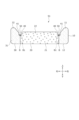
- 3 is a sectional view taken along line III-III in FIG. 2.
- FIG. FIG. 3 is a cross-sectional view of a pad material of Modification 1.
- FIG. 7 is a cross-sectional view of a pad material of Modification 2.
- FIG. 7 is a cross-sectional view of a pad material of Modification 3.
- FIG. 7 is a cross-sectional view of a pad material of Modification 4.
- FIG. 7 is a cross-sectional view of a pad material according to modification 5.
- FIG. 7 is a top view of a pad material of Modification 6.
- FIG. 9 is a sectional view taken along line XX in FIG. 9; FIG.
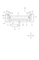
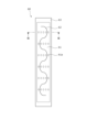
- FIG. 3 is a top view of the seat heater. 12 is a sectional view taken along line XII-XII in FIG. 11.
- FIG. 7 is a perspective view of a vehicle seat according to Modification Example 7;
- FIG. 7 is a perspective view of a vehicle seat according to Modification 8.
- FIG. 7 is a perspective view of a vehicle seat according to modification 9.
- FIG. 7 is a perspective view of a vehicle seat according to Modification 10.
- FIG. 7 is a perspective view of a vehicle seat according to Modification 11;
- the sitting seat of this embodiment is, for example, a vehicle seat S installed in a vehicle.
- vehicle seat S may be, for example, a seat installed in a ship, an aircraft, or the like.
- the sitting seat is not limited to the vehicle seat S, but may be a seat such as a general chair, sofa, or cushion.
- the "front-rear direction” refers to the front-rear direction of the vehicle seat S, and is a direction that coincides with the direction in which the vehicle travels.
- the "seat width direction” is the width direction of the vehicle seat S, and is a direction that coincides with the left-right direction as seen from a person seated on the vehicle seat S.
- the “vertical direction” refers to the vertical direction of the vehicle seat S, and is a direction that coincides with the vertical direction when the vehicle is traveling on a horizontal plane.
- the vehicle seat S mainly includes a seat back 1, a seat cushion 2 connected to the lower part of the seat back 1, and a headrest 3 connected to the upper part of the seat back 1. It is configured.
- the seat back 1 is a backrest portion that supports the back of a seated person from behind, and is constructed by placing a pad material 1a on a seat frame 4 (back frame 4a) serving as a skeleton and covering it with a skin material 1b. has been done.
- the seat cushion 2 is a seating part that supports a seated person from below, and a padding material 2a is placed on a seat frame 4 (cushion frame 4b) serving as a skeleton, and a skin material 2b is placed over the padding material 2a. It is covered and constructed.
- the headrest 3 is a head that supports the head of a seated person from behind, and is constructed by placing a padding material 3a on a not-shown headrest pillar serving as a core material, and covering the padding material 3a with a skin material 3b.
- FIG. 2 shows a cushion main body portion 10 that is a pad material 2a that constitutes the seat cushion 2.
- the structure of the padding material 1a constituting the seat back 1 is substantially the same as that of the padding material 2a constituting the seat cushion 2, so a description thereof will be omitted.
- the cushion main body 10 is a pad material 2a for supporting a seated person, and includes a first cushion member 20 serving as a seating portion, a second cushion member 30 provided around the first cushion member 20, and a cushion main body. 10 and an engaging portion 50 provided in the groove 40.
- the cushion main body portion 10 is covered with the skin material 2b by suspending the skin material 2b by the engaging portion 50 provided in the groove portion 40.
- the first cushion member 20, the second cushion member 30, and the engaging portion 50 are integrally formed, for example, by insert molding.
- the first cushion member 20 has a base portion 21 provided at the center of the cushion body portion 10, as shown in FIGS. 2 and 3. As shown in FIGS.
- the base portion 21 has a seating surface 22 that supports a seated person from below.
- the seating surface 22 is a cushion member having a thickness in the vertical direction, and is formed in a substantially inverted U shape when viewed from above. Note that the seating surface 22 refers to the surface 11 of the base portion 21 on the side of the seated person other than the groove portion 40.
- the second cushion member 30 includes a side portion 31 disposed on the outside of the base portion 21 in the seat width direction, and a side portion 31 that extends from the side portion 31 toward the seated person (upward). It has an overhang part 32 that supports the from the side.
- the side portion 31 is a cushion member having substantially the same thickness as the base portion 21 in the vertical direction, and is formed in a substantially inverted U shape when viewed from above.
- the projecting part 32 is a cushion member that is integrally formed of the same material as the side part 31, projects upward from the side part 31, and supports the seated person from the side.
- the projecting portion 32 has a substantially U-shape when viewed from above, and is formed to surround the base portion 21.
- the projecting portion 32 has a substantially inverted U shape when viewed from above, and is formed at the base end portions 21a on both sides of the base portion 21 in the sheet width direction and the rear end portion 21b of the base portion 21. , are arranged so as to surround the base portion 21 on three sides. That is, the protruding portion 32 is not formed at the front end portion of the base portion 21.
- the overhanging portion 32 when a seated person sits on the base portion 21, since the overhanging portion 32 is not provided at a position corresponding to the thigh of the seated person, the overhanging portion 32 that overhangs upward reduces sitting comfort. You can prevent this from happening.
- the first cushion member 20 has higher hardness than the second cushion member 30.
- the first cushion member 20 is a soft cushion member made of urethane foam or the like.
- the second cushion member 30 is a hard cushion member made of biomass urethane. That is, the cushion main body portion 10 is composed of two types of cushion members that are made of different materials and have different hardnesses.
- the first cushion member 20 is, for example, a urethane foam other than biomass urethane (hereinafter referred to as non-biomass urethane) formed by foam molding using a urethane foam material.
- non-biomass urethane is a cushion member made of a softer material than biomass urethane.
- the non-biomass urethane preferably has a high impact resilience and low hardness in order to improve the seating feeling.
- the entire base portion 21 is made of non-biomass urethane. Therefore, by using non-biomass urethane, which is softer than biomass urethane, in the seating surface 22, the comfort of sitting can be improved.
- the second cushion member 30 is made of, for example, biomass urethane.
- the biomass urethane includes a hard polyurethane foam with a high biomass ratio.
- the side portion 31 and the overhang portion 32 are entirely made of biomass urethane. Therefore, the side portion 31 and the overhang portion 32 of the second cushion member 30 have higher hardness than the base portion 21 of the first cushion member 20 and are less likely to bend, so that the first cushion of low hardness may be affected by the load from the seated person. Deformation of the member 20 can be suppressed.
- the configuration of the cushion main body 10 may be applied to the pad material 3a that constitutes the headrest 3.
- the base portion 21 corresponding to at least the portion corresponding to the head of the seated person is formed of a different material from the projecting portion 32 of the pad material 3a.
- the base portion 21 is made of non-biomass urethane
- the side portions 31 and the overhang portions 32 are made of biomass urethane. Therefore, since the base portion 21 of the pad material 3a for the headrest 3 is made of non-biomass urethane, it can have higher durability than biomass urethane which is brittle and weak against impact. Therefore, damage to the headrest 3 can be suppressed.
- the groove portion 40 is a suspension groove for suspending the skin material 2b, and is formed on the surface 11 of the cushion body portion 10. As shown in FIGS. 2 and 3, the groove portion 40 is formed near the boundary B between the base portion 21 of the first cushion member 20 and the side portion 31 of the second cushion member 30, and has a substantially inverted U-shape when viewed from above. has a condition. Specifically, the groove portion 40 is formed in the base portion 21 of the first cushion member 20 near the boundary portion B on the seating surface 22 side of the cushion main body portion 10 . In other words, the bottom surface 41 of the groove portion 40 is provided on the first cushion member 20 .
- the groove part 40 is a suspension groove for suspending the skin material 2b
- the groove portion 40 may be a groove for arranging a heating element of a heater provided on the surface 11 of the cushion main body portion 10, a groove for passing through when an air bag of an air bag device is inflated, etc. good.
- the engaging portion 50 is a hanging member for hanging the skin material 2b, and is, for example, a clip having a substantially V-shaped cross section.
- the engaging portion 50 is made of resin, such as polyacetal (POM) resin, polypropylene (PP) resin, polyamide (PA) resin, polycarbonate (PC) resin, or the like.
- the engaging portion 50 is preferably formed of a relatively strong polyacetal (POM) resin.
- the engaging portion 50 may have a U-shaped or C-shaped cross section.
- the material is not limited to a clip, but may be a hanging member such as a metal wire.
- the engaging portion 50 is not limited to a hanging member, but may be a hanging hole for hanging the skin material 2b.
- a plurality of engaging portions 50 are provided inside the groove portion 40 at predetermined intervals.
- the engaging portion 50 is integrally formed during foam molding of the cushion body portion 10, and is attached to the cushion body portion 10 while being embedded within the groove portion 40.
- the engaging portion 50 is provided on the first cushion member 20 and is attached so as to be partially embedded in the bottom surface 41 of the groove portion 40.
- the boundary part B between the base part 21 of the first cushion member 20 and the side part 31 of the second cushion member 30 is located at the seat provided on the surface 11 of the cushion body part 10 (pad material 2a). It extends from the surface 22 toward the back surface 12 on the opposite side to the seating surface 22 so as to be perpendicular to the seating surface 22 of the cushion body 10 .
- the boundary surface between the base portion 21 of the first cushion member 20 and the side portion 31 of the second cushion member 30 is perpendicular to the seating surface 22 from the boundary end B1 provided in the groove portion 40. It is located in Therefore, since the overhanging part 32 and side part 31 of the second cushion member 30 made of biomass urethane are not provided below the seating surface 22, the high hardness of the biomass urethane reduces sitting comfort. can be suppressed.
- a boundary end B1 on the seating surface 22 side of the boundary B between the first cushion member 20 and the second cushion member 30 is provided within the groove 40 and is not exposed to the seating surface 22.
- the boundary end B1 which is the upper end portion of the boundary between the base portion 21 of the first cushion member 20 and the side portion 31 of the second cushion member 30, is provided on the bottom surface 41 of the groove portion 40. Therefore, at the boundary B between the first cushion member 20 and the second cushion member 30, both the end on the seated person's side and the end on the back surface 12 side, which is the opposite side to the seated person, are attached to the seating surface 22. Not provided.
- the cushion main body portion 10 is composed of the first cushion member 20 and the second cushion member 30 having different hardnesses, the seated person It is possible to improve the comfort of sitting without making you feel uncomfortable. Furthermore, since the engaging portion 50 is provided on the side of the first cushion member 20 made of non-biomass urethane which is softer than the second cushion member 30 made of biomass urethane, when a load from a seated person is applied to the cushion main body 10. In addition, the engaging portion 50 is more likely to sink in, and the seating comfort can be further improved without making the seated person feel uncomfortable. Furthermore, since the entire overhang 32 is made of biomass urethane, the boundary B between the first cushion member 20 and the second cushion member 30 is not exposed in the overhang 32, which further improves sitting comfort. be able to.
- the groove portion 40 is formed in the base portion 21 of the first cushion member 20 near the boundary portion B on the seating surface 22 side of the cushion body portion 10.
- the bottom surface 41 of the groove portion 40 is provided on the first cushion member 20 and the second cushion member 30.
- the engaging portion 50 is attached so as to be partially embedded in the bottom surface 41 of the groove portion 40 so as to straddle the boundary portion B between the first cushion member 20 and the second cushion member 30.
- the boundary end B1 on the seating surface 22 side of the boundary B between the first cushion member 20 and the second cushion member 30 is provided within the groove 40, It is not exposed to the seating surface 22. Therefore, it is possible to improve the sitting comfort at the boundary B between the first cushion member 20 and the second cushion member 30 without making the seated person feel uncomfortable. Further, since the engaging portion 50 is attached to the bottom surface 41 of the groove portion 40 so as to straddle the boundary portion B between the first cushion member 20 and the second cushion member 30, the first cushion member 20 and the second cushion member 20 are made of different materials and have different hardnesses. The bonding strength of the cushion member 30 can be increased.
- the groove portion 40 is formed in the side portion 31 of the second cushion member 30 near the boundary portion B on the seating surface 22 side of the cushion main body portion 10.
- the bottom surface 41 of the groove portion 40 is provided on the second cushion member 30.
- the engaging portion 50 is provided on the second cushion member 30 and is attached so that a portion thereof is embedded in the bottom surface 41 of the groove portion 40 .
- the boundary end B1 on the seating surface 22 side of the boundary B between the first cushion member 20 and the second cushion member 30 is provided within the groove 40, It is not exposed to the seating surface 22. Therefore, it is possible to improve the sitting comfort at the boundary B between the first cushion member 20 and the second cushion member 30 without making the seated person feel uncomfortable. Furthermore, since the engaging portion 50 is provided on the side of the second cushion member 30 made of biomass urethane, which is harder than the first cushion member 20 made of non-biomass urethane, the attachment strength of the engaging portion 50 to the cushion body 10 is reduced. can be increased. Therefore, the attachment strength of the skin material 2b to the pad material 2a can be increased.
- a third modification of the vehicle seat S will be described based on FIG. 6. Note that descriptions of the same content as those of the vehicle seats S, S1, and S2 described above will be omitted.
- the boundary B between the base portion 21 of the first cushion member 20 and the side portion 31 of the second cushion member 30 is the seating surface 22 provided on the surface 11 of the cushion body portion 10.
- a side portion 31 extends from the seat toward the back surface 12 on the opposite side from the seating surface 22 so as to fit under the seating surface 22.
- the boundary surface between the base portion 21 of the first cushion member 20 and the side portion 31 of the second cushion member 30 extends from the boundary end B1 provided in the groove portion 40 to the seating surface 22 in the seat width direction. It is arranged so that it slopes inward.
- the first cushion member 20 made of non-biomass urethane with low hardness is affected by the load from the seated person. Deformation can be suppressed.
- the first cushion member 20 includes a base portion 21 provided at the center of the cushion body portion 10 and a second side portion 23 located outside the base portion 21 in the seat width direction. and has. That is, in the cushion main body part 10, the base part 21 and the second side part 23 are made of non-biomass urethane, and the overhang part 32 is made of biomass urethane.
- the second cushion member 30 has only a side portion 31 disposed on the outer side of the base portion 21 in the seat width direction, and is not provided with an overhang portion 32.
- the vehicle seat S6 of Modified Example 6 includes a pad material 2a (cushion main body portion 10) of the seat cushion 2, a skin material 2b covering the pad material 2a, and a sheet-like material provided between the pad material 2a and the skin material 2b. It has a seat heater 60 and a blower device 70 provided below the pad material 2a. Note that the seat heater 60 and the air blower 70 may be provided on the seat back 1 or the headrest 3.
- the seat heater 60 is a planar heating element that warms the seat cushion 2, and is attached inside the skin material 2b of the seat cushion 2 and provided on the pad material 2a (cushion main body portion 10). Note that the seat heater 60 is connected to a power source and a control device via a harness (not shown). As shown in FIGS. 9 to 12, the seat heater 60 includes a sheet-shaped heater base material 61, a heater wire 62 attached to the heater base material 61, and a heater base material 61 interposed between the overhang portion 32 and the heater base material 61. and a heat insulating material 63 having heat insulating properties.
- the heater base material 61 is made of a stretchable cloth material and is a base portion of the seat heater 60.
- the heater base material 61 is provided on the mounting surface 32a of the overhanging portion 32 of the cushion main body portion 10, as shown in FIGS. 9 and 10.
- the attachment surface 32a is a surface of the projecting portion 32 that is inclined toward the seated person side (inner side in the seat width direction).
- the heater base material 61 is formed with a passage hole 61a that penetrates in the thickness direction of the heater base material 61.
- the passage hole 61a is formed at a position facing a through hole 63a of a heat insulating material 63, which will be described later.
- the heater wire 62 is fixed onto the heater base material 61 by adhesive, as shown in FIGS. 9, 11, and 12. Note that it may be attached onto the heater base material 61 by sewing or the like.
- the heater wire 62 extends from the rear end portion of the heater base material 61 toward the front side while meandering.
- the heat insulating material 63 is a member with low thermal conductivity made of, for example, glass wool or rock wool, and makes it difficult for heat from the heater wire 62 to be transmitted to the overhanging portion 32 of the cushion body 10 .
- the heat insulating material 63 is attached to the mounting surface 32a of the overhanging portion 32 of the cushion main body portion 10, as shown in FIGS. 9 and 10.
- the heat insulating material 63 is formed with a through hole 63a through which air from an air passage 71 (described later) passes.
- the through hole 63a penetrates the heat insulating material 63 in the thickness direction and is formed at a position facing the passage hole 61a of the heater base material 61.
- the blower device 70 is a blower device that sends air to a person sitting on the seat cushion 2, and is provided below the seat cushion 2. Note that the seat heater 60 is connected to a power source and a control device via a harness (not shown). As shown in FIG. 10, the blower device 70 has a blower passage 71 that connects to the first air passage 24 of the cushion body 10. The air sent from the blower device 70 passes through the first ventilation path 24 and the second ventilation path 33 via the ventilation path 71, and is directed toward the seated person from the air outlet 33a formed in the overhang 32. Sent.
- the second cushion member 30 made of biomass urethane is arranged avoiding the seating area of the seated person, so it is possible to improve the sitting comfort of the vehicle seat S7.
- a second cushion member 30 made of biomass urethane is used for the cushion main body 10 corresponding to the bulging portion 2c, which is a side portion of the seat cushion 2. Further, in the seat cushion 2, the second cushion member 30 made of biomass urethane is used for the cushion main body portion 10 corresponding to the seat front end portion 2d, which is the front central portion of the seat cushion 2. Note that the portion of the seat back 1 other than the back bulge 1c and the upper backrest 1d, the portion of the seat cushion 2 other than the bulge 2c and the seat front end 2d, and the cushion main body 10 corresponding to the headrest 3 are made of non-biomass. Made of urethane.
- the second cushion member 30 made of biomass urethane is arranged so as to avoid the seating area of the seated person, thereby improving the sitting comfort of the vehicle seat S9.
- the vehicle seat S10 of Modification 10 includes a seat back 1, a seat cushion 2 connected to the lower part of the seat back 1, and a headrest 3 connected to the upper part of the seat back 1. It is mainly composed of.
- a second cushion member 30 made of biomass urethane is used for the cushion main body 10 corresponding to the decorated back decoration part 1e, which is the central part of the seat back 1.
- the second cushion member 30 made of biomass urethane is used for the cushion main body 10 corresponding to the decorated cushion decorative portion 2f which is the central portion of the seat cushion 2.
- the portions of the seat back 1 other than the back decoration portion 1e, the portions of the seat cushion 2 other than the cushion decoration portion 2f, and the cushion body portion 10 corresponding to the headrest 3 are formed of non-biomass urethane.
- the pad material of the present invention is used for a sitting seat and supports a seated person, and the pad material is provided with a first cushion member and adjacent to the first cushion member. , a second cushion member having higher hardness than the first cushion member, and a seating surface provided on the surface of the pad material has a groove recessed toward the back surface of the pad material, Of the boundary between the first cushion member and the second cushion member, an end located on the seating surface side is provided in the groove and is provided so as not to be exposed to the seating surface. , is solved by.
- the sitting seat is provided with a padding material, a skin material covering the padding material, and an engaging part provided on the padding material for suspending the skin material on the padding material,
- the joint portion may be attached to the bottom surface of the groove portion of the pad material.
- the second cushion member is formed of biomass urethane
- the bottom surface of the groove is provided on the first cushion member
- the engaging portion is provided on the first cushion member
- the bottom surface of the groove is provided on the first cushion member. It is preferable that it be provided on the bottom surface of.
- the second cushion member is formed of biomass urethane
- the bottom surface of the groove portion is provided on the second cushion member
- the engaging portion is provided on the second cushion member
- the bottom surface of the groove portion is provided on the second cushion member. It is preferable that it be provided on the bottom surface of.
- the engagement portion is provided on the side of the second cushion member made of biomass urethane that is harder than the first cushion member made of non-biomass urethane, so the strength of attachment of the engagement portion to the pad material can be increased. .
- the vehicle seat includes a pad material for supporting a seated person and a seat frame on which the pad material is arranged, the pad material being a first a cushion member and a second cushion member having a harder hardness than the first cushion member; a groove portion is formed in the seating surface of the pad material; and the first cushion member and the second cushion member
- a vehicle seat used in a car was explained as a specific example, but the invention is not limited to a two-wheeled seat for a motorcycle, a seat for a vehicle such as a train or a bus, a seat for a vehicle such as an airplane or a ship, etc. In addition, it can be used for various seats such as office chairs for work, wheelchairs, children's chairs for shopping carts, etc.
- the vehicle seat according to the present invention has been mainly described.
- the embodiments described above are merely examples for facilitating understanding of the present invention, and do not limit the present invention.
- the present invention may be modified and improved without departing from its spirit, and it goes without saying that the present invention includes equivalents thereof.
Landscapes
- Engineering & Computer Science (AREA)
- Aviation & Aerospace Engineering (AREA)
- Transportation (AREA)
- Mechanical Engineering (AREA)
- Seats For Vehicles (AREA)
- Mattresses And Other Support Structures For Chairs And Beds (AREA)
- Chair Legs, Seat Parts, And Backrests (AREA)
Abstract
Description
また、パッド材の全体又は一部が、ウレタンフォームよりも硬質であるバイオマスウレタンで形成される場合には、環境に配慮することができるものの、更なる座り心地の向上が求められていた。
上記構成により、環境に配慮しながら座り心地を向上させ、着座者に違和感を与えることのないパッド材を実現できる。
詳しく述べると、環境にやさしいバイオマスウレタンを前記張出部に用いることで、環境に配慮したパッド材を実現でき、着座面においてはバイオマスウレタンよりも軟質なウレタンフォームを用いることで座り心地を向上できる。
また、張出部の全体が高硬度のバイオマスウレタンで形成されるため、張出部においてクッション部材の境界部が露出しないため、着座者に違和感を与えずに、座り心地を向上させることができる。
上記構成により、張出部及びサイド部の全体が高硬度のバイオマスウレタンで形成される。そのため、張出部及びサイド部の剛性を高まり、座り心地を向上しつつ、パッド材のホールド感を高めることができる。
上記構成により、バイオマスウレタンで形成された張出部及びサイド部が、着座面に設けられていないため、高硬度のバイオマスウレタンによって座り心地が低下してしまうことを抑制できる。
上記構成により、ベース部の周囲に剛性の高い張出部を設けることで、座り心地を向上しつつ、パッド材のホールド感を高めることができる。
上記構成により、剛性の高い張出部を着座者の大腿部に対応する位置に設けないようにすることで、高硬度のバイオマスウレタンによって座り心地が低下してしまうことを抑制できる。
上記構成により、ヘッドレストの損傷を抑制できる。詳しく述べると、バイオマスウレタンは高硬度であるが、脆く衝撃に弱い。そのため、ヘッドレストにバイオマスウレタンを用いると、衝撃によりヘッドレストが損傷するおそれがある。したがって、ヘッドレスト用パッド材をバイオマスウレタン以外の材料で形成することにより、ヘッドレストの損傷を抑制できる。
上記構成により、断熱材によってヒータ線の熱がバイオマスウレタンに伝わりにくくすることができる。したがって、バイオマスウレタンがヒータ線からの熱の影響を受けて劣化することを抑制できる。
上記構成により、送風装置からの風が断熱材を通過し易くなり、着座者の温感や冷感を良好なものとすることができる。
上記構成により、送風装置からの風がヒータ基材を通過し易くなり、着座者の温感や冷感をさらに良好なものとすることができる。
上記構成により、環境に配慮しながら座り心地を向上させ、着座者に違和感を与えることのない乗り物用シートを実現できる。
また本発明によれば、張出部及びサイド部の剛性を高まり、座り心地を向上しつつ、パッド材のホールド感を高めることができる。
また本発明によれば、高硬度のバイオマスウレタンによって座り心地が低下してしまうことを抑制できる。
また本発明によれば、座り心地を向上しつつ、パッド材のホールド感を高めることができる。
また本発明によれば、ヘッドレストの損傷を抑制できる。
また本発明によれば、バイオマスウレタンがヒータ線からの熱の影響を受けて劣化することを抑制できる。
また本発明によれば、着座者の温感や冷感を良好なものとすることができる。
また本発明によれば、着座者の温感や冷感をさらに良好なものとすることができる。
本実施形態の着座シートは、図1に示すように、例えば車両に設置される乗り物用シートSである。なお、乗り物用シートSは、例えば、船舶や航空機などに設置されるシートであってもよい。また、着座シートは、乗り物用シートSに限らず、一般的な椅子、ソファ又はクッション等のシートであってもよい。
乗り物用シートSは、図1に示すように、シートバック1と、シートバック1の下方部分に連結されるシートクッション2と、シートバック1の上方部分に連結されるヘッドレスト3と、から主に構成されている。
シートバック1は、着座者の背中を後方から支持する背もたれ部であって、骨格となるシートフレーム4(バックフレーム4a)に、パッド材1aを載置して、表皮材1bで被覆されて構成されている。
シートクッション2は、着座者を下方から支持する着座部であって、骨格となるシートフレーム4(クッションフレーム4b)に、パッド材2aを載置して、パッド材2aの上から表皮材2bによって被覆されて構成されている。
ヘッドレスト3は、着座者の頭を後方から支持する頭部であって、芯材となる不図示のヘッドレストピラーにパッド材3aを載置して、表皮材3bで被覆されて構成されている。
クッション本体部10は、溝部40に設けられた係合部50によって、表皮材2bが吊り込まれることで、表皮材2bに覆われる。
クッション本体部10は、例えば、インサート成型によって、第1クッション部材20と第2クッション部材30、及び係合部50が一体的に形成される。
ベース部21は、着座者を下方から支持する着座面22を有する。着座面22は、上下方向に厚みを有するクッション部材であり、上面視で略逆U字状に形成される。なお、着座面22とは、ベース部21における溝部40以外の着座者側の表面11を言う。
サイド部31は、上下方向にベース部21と略同じ厚みを有するクッション部材であり、上面視で略逆U字状に形成される。
張出部32は、サイド部31と同じ材料で一体的に形成され、サイド部31から上方へ張り出し、着座者を側方から支持するクッション部材である。
つまり、ベース部21の前端部には、張出部32が形成されない。したがって、着座者がベース部21に着座したとき、着座者の大腿部に対応する位置に張出部32が設けられていないため、上方に張り出す張出部32によって、座り心地が低下してしまうことを抑制できる。
ベース部21は、全体が非バイオマスウレタンで形成される。したがって、着座面22において、バイオマスウレタンよりも軟質な非バイオマスウレタンを用いることにより、座り心地を向上することができる。
サイド部31及び張出部32は、全体がバイオマスウレタンで形成される。したがって、第2クッション部材30のサイド部31及び張出部32は、第1クッション部材20のベース部21よりも高硬度であり、撓みにくいため、着座者からの荷重によって低硬度の第1クッション部材20が変形してしまうことを抑制できる。
したがって、ヘッドレスト3用のパッド材3aのベース部21は、非バイオマスウレタンで形成されるため、脆く衝撃に弱いバイオマスウレタンよりも耐久性を高くすることができる。そのため、ヘッドレスト3の損傷を抑制することができる。
具体的には、溝部40は、クッション本体部10の着座面22側における境界部Bの近傍であって、第1クッション部材20のベース部21に形成される。言い換えると、溝部40の底面41は、第1クッション部材20に設けられている。
なお、本実施形態では、溝部40が表皮材2bを吊り込むための吊り込み溝である例を説明したが、これに限らない。例えば、溝部40は、クッション本体部10の表面11に設けられたヒータの発熱体を配置するための溝や、エアバッグ装置のエアバッグが膨張した際に通過するための溝等であってもよい。
係合部50は、樹脂製であり、例えばポリアセタール(POM)樹脂、ポリプロピレン(PP)樹脂、ポリアミド(PA)樹脂、ポリカーボネート(PC)樹脂等から形成される。なお、係合部50は、比較的強度の高いポリアセタール(POM)樹脂により形成されるとよい。
なお、係合部50は、断面がU字状、又はC字状に形成されてもよい。また、クリップに限らず金属ワイヤ等の吊り込み部材であってもよい。さらに、係合部50は、吊り込み部材に限らず、表皮材2bを吊り込むための吊り込み孔であってもよい。
詳しく述べると、係合部50は、図3に示すように、第1クッション部材20上に設けられ、溝部40の底面41に一部が埋設されるように取り付けられる。
したがって、バイオマスウレタンで形成された第2クッション部材30の張出部32及びサイド部31が、着座面22の下方に設けられていないため、高硬度のバイオマスウレタンによって座り心地が低下してしまうことを抑制できる。
詳しく述べると、第1クッション部材20のベース部21と第2クッション部材30のサイド部31との境界面における上端部分である境界端部B1は、溝部40の底面41に設けられる。したがって、第1クッション部材20と第2クッション部材30との境界部Bにおける、着座者側の端部も、着座者側とは反対側である裏面12側の端部も、着座面22には設けられていない。
また、バイオマスウレタンからなる第2クッション部材30よりも軟質な非バイオマスウレタンからなる第1クッション部材20側に係合部50が設けられるため、着座者からの荷重がクッション本体部10にかかったときに、係合部50が沈み込みやすくなり、着座者に違和感を与えずに、より座り心地を向上させることができる。
さらに、張出部32の全体がバイオマスウレタンで形成されるため、張出部32において第1クッション部材20と第2クッション部材30との境界部Bが露出しないため、より一層座り心地を向上させることができる。
次に、乗り物用シートSの変形例1について、図4に基づいて説明する。なお、上述の乗り物用シートSと重複する内容については説明を省略する。
変形例1の乗り物用シートS1では、溝部40が、クッション本体部10の着座面22側における境界部Bの近傍であって、第1クッション部材20のベース部21に形成される。言い換えると、溝部40の底面41は、第1クッション部材20及び第2クッション部材30に設けられている。
係合部50は、図4に示すように、第1クッション部材20及び第2クッション部材30の境界部Bを跨ぐように、溝部40の底面41に一部が埋設されるように取り付けられる。
また、係合部50が第1クッション部材20及び第2クッション部材30の境界部Bを跨ぐように、溝部40の底面41に取り付けられるため、材料や硬度が異なる第1クッション部材20及び第2クッション部材30の結合強度を高めることができる。
次に、乗り物用シートSの変形例2について、図5に基づいて説明する。なお、上述の乗り物用シートS、S1と重複する内容については説明を省略する。
変形例2の乗り物用シートS2では、溝部40が、クッション本体部10の着座面22側における境界部Bの近傍であって、第2クッション部材30のサイド部31に形成される。言い換えると、溝部40の底面41は、第2クッション部材30に設けられている。
係合部50は、図5に示すように、第2クッション部材30上に設けられ、溝部40の底面41に一部が埋設されるように取り付けられる。
また、非バイオマスウレタンからなる第1クッション部材20よりも硬質なバイオマスウレタンからなる第2クッション部材30側に係合部50が設けられるため、係合部50のクッション本体部10への取付強度を高めることができる。したがって、表皮材2bのパッド材2aへの取付強度を高めることができる。
次に、乗り物用シートSの変形例3について、図6に基づいて説明する。なお、上述の乗り物用シートS、S1、S2と重複する内容については説明を省略する。
変形例3の乗り物用シートS3では、第1クッション部材20のベース部21と第2クッション部材30のサイド部31との境界部Bは、クッション本体部10の表面11に設けられた着座面22から、着座面22とは反対側の裏面12へ向かって、着座面22の下方にサイド部31が入り込むように延びている。言い換えると、第1クッション部材20のベース部21と第2クッション部材30のサイド部31との境界面は、溝部40内に設けられた境界端部B1から着座面22に対してシート幅方向の内側に傾斜するように配置されている。
次に、乗り物用シートSの変形例4について、図7に基づいて説明する。なお、上述の乗り物用シートS、S1~S3と重複する内容については説明を省略する。
変形例4の乗り物用シートS4では、第1クッション部材20が、クッション本体部10における中央部に設けられるベース部21と、ベース部21のシート幅方向における外側に配置される第2サイド部23と、を有する。つまり、クッション本体部10のうち、ベース部21及び第2サイド部23が非バイオマスウレタンで形成され、張出部32がバイオマスウレタンで形成される。
したがって、バイオマスウレタンで形成された第2クッション部材30の張出部32の体積を低下させることができ、座り心地を向上させることができる。
次に、乗り物用シートSの変形例5について、図8に基づいて説明する。なお、上述の乗り物用シートS、S1~S4と重複する内容については説明を省略する。
変形例5の乗り物用シートS5では、第2クッション部材30は、ベース部21のシート幅方向における外側に配置されるサイド部31のみを有しており、張出部32は設けられていない。
次に、乗り物用シートSの変形例6について、図9~図12に基づいて説明する。なお、上述の乗り物用シートS、S1~S5と重複する内容については説明を省略する。
変形例6の乗り物用シートS6は、シートクッション2のパッド材2a(クッション本体部10)と、パッド材2aを覆う表皮材2bと、パッド材2a及び表皮材2bの間に設けられるシート状のシートヒータ60と、パッド材2aの下方に設けられる送風装置70と、を有する。なお、シートヒータ60及び送風装置70は、シートバック1やヘッドレスト3に設けられてもよい。
シートヒータ60は、図9~図12に示すように、シート状のヒータ基材61と、ヒータ基材61に取り付けられるヒータ線62と、張出部32とヒータ基材61との間に介在され、断熱性を有する断熱材63と、を有する。
ヒータ基材61には、図12に示すように、ヒータ基材61の厚み方向に貫通する通過孔61aが形成される。通過孔61aは、後述する断熱材63の貫通孔63aと対向する位置に形成される。
ヒータ線62は、ヒータ基材61の後端部分から前方側に向かって蛇行しながら延びている。
断熱材63には、図12に示すように、後述する送風路71からの風を通過させる貫通孔63aが形成される。貫通孔63aは、断熱材63の厚み方向に貫通し、ヒータ基材61の通過孔61aと対向する位置に形成される。
このように、第2クッション部材30の張出部32とヒータ基材61との間に断熱材63が設けられることによって、バイオマスウレタンで形成された第2クッション部材30がヒータ線62からの熱の影響を受けて劣化することを抑制できる。
送風装置70は、図10に示すように、クッション本体部10の第1通気路24と接続する送風路71を有する。送風装置70から送られた空気は、送風路71を介して、第1通気路24及び第2通気路33を通過し、張出部32に形成された吹出口33aから、着座者に向かって送られる。
このように、ヒータ基材61と断熱材63に、それぞれ通過孔61a及び貫通孔63aが設けられることによって、送風装置70からの風がヒータ基材61と断熱材63を通過し易くなり、着座者の温感や冷感を良好なものとすることができる。
次に、乗り物用シートSの変形例7について、図13に基づいて説明する。なお、上述の乗り物用シートS、S1~S6と重複する内容については説明を省略する。
変形例7の乗り物用シートS7は、図13に示すように、シートバック1と、シートバック1の下方部分に連結されるシートクッション2と、シートバック1の上方部分に連結されるヘッドレスト3と、シートクッション2の前方部分に連結されるフットレスト5と、から主に構成されている。フットレスト5は、着座者の脚部を下方から支持する部材である。
また、シートクッション2において、シートクッション2の側方部分である膨出部2cに対応するクッション本体部10は、バイオマスウレタンからなる第2クッション部材30が用いられる。
なお、シートバック1におけるバック膨出部1c以外の部分、シートクッション2における膨出部2c以外の部分、ヘッドレスト3、及びフットレスト5に対応するクッション本体部10は、非バイオマスウレタンで形成される。
次に、乗り物用シートSの変形例8について、図14に基づいて説明する。なお、上述の乗り物用シートS、S1~S7と重複する内容については説明を省略する。
変形例8の乗り物用シートS8は、図14に示すように、シートバック1と、シートバック1の下方部分に連結されるシートクッション2と、シートバック1の上方部分に連結されるヘッドレスト3と、から主に構成されている。
また、シートバック1において、シートバック1の上方中央部分である背もたれ上部1dに対応するクッション本体部10は、バイオマスウレタンからなる第2クッション部材30が用いられる。
また、シートクッション2において、シートクッション2の前方中央部分であるシート前端部2dに対応するクッション本体部10は、バイオマスウレタンからなる第2クッション部材30が用いられる。
なお、シートバック1におけるバック膨出部1c及び背もたれ上部1d以外の部分、シートクッション2における膨出部2c及びシート前端部2d以外の部分、及びヘッドレスト3に対応するクッション本体部10は、非バイオマスウレタンで形成される。
次に、乗り物用シートSの変形例9について、図15に基づいて説明する。なお、上述の乗り物用シートS、S1~S8と重複する内容については説明を省略する。
変形例9の乗り物用シートS9は、図15に示すように、シートバック1と、シートバック1の下方部分に連結されるシートクッション2と、シートバック1の上方部分に連結されるヘッドレスト3と、から主に構成されている。
また、シートクッション2において、シートクッション2の後方中央部分であるシート後端部2eに対応するクッション本体部10は、バイオマスウレタンからなる第2クッション部材30が用いられる。
なお、シートバック1、シートクッション2における膨出部2c及びシート後端部2e以外の部分、及びヘッドレスト3に対応するクッション本体部10は、非バイオマスウレタンで形成される。
次に、乗り物用シートSの変形例10について、図16に基づいて説明する。なお、上述の乗り物用シートS、S1~S9と重複する内容については説明を省略する。
変形例10の乗り物用シートS10は、図16に示すように、シートバック1と、シートバック1の下方部分に連結されるシートクッション2と、シートバック1の上方部分に連結されるヘッドレスト3と、から主に構成されている。
なお、シートバック1、シートクッション2、及びヘッドレスト3における側方部3c以外の部分、に対応するクッション本体部10は、非バイオマスウレタンで形成される。
次に、乗り物用シートSの変形例11について、図17に基づいて説明する。なお、上述の乗り物用シートS、S1~S10と重複する内容については説明を省略する。
変形例11の乗り物用シートS11は、図17に示すように、シートバック1と、シートバック1の下方部分に連結されるシートクッション2と、シートバック1の上方部分に連結されるヘッドレスト3と、から主に構成されている。
シートクッション2において、シートクッション2の中央部分であって装飾が施されたクッション装飾部2fに対応するクッション本体部10は、バイオマスウレタンからなる第2クッション部材30が用いられる。
なお、シートバック1におけるバック装飾部1e以外の部分、シートクッション2におけるクッション装飾部2f以外の部分、及びヘッドレスト3に対応するクッション本体部10は、非バイオマスウレタンで形成される。
本発明のパッド材によれば、着座シートに用いられ、着座者を支持するためのパッド材であって、前記パッド材は、第1クッション部材と、前記第1クッション部材に隣り合って設けられ、前記第1クッション部材よりも硬度が高い第2クッション部材と、を有し、前記パッド材の表面に設けられた着座面には、前記パッド材の裏面に向かって窪む溝部が形成され、前記第1クッション部材と前記第2クッション部材との境界部のうち、前記着座面側に位置する端部が、前記溝部に設けられ、かつ、前記着座面に露出しないように設けられていること、により解決される。
詳しく述べると、環境にやさしいバイオマスウレタンを前記張出部に用いることで、環境に配慮したパッド材を実現でき、着座面においてはバイオマスウレタンよりも軟質なウレタンフォームを用いることで座り心地を向上できる。
また、クッション部材の境界部が着座面に露出しないため、着座者に違和感を与えずに、座り心地を向上させることができる。
上記構成により、吊り込み溝の凹部を利用して、クッション部材の境界部を着座面に露出させないため、簡易な構成で、着座者に違和感を与えずに、座り心地を向上できる。
上記構成により、バイオマスウレタンからなる第2クッション部材よりも軟質な非バイオマスウレタンからなる第1クッション部材側に係合部が設けられるため、着座者からの荷重がパッド材にかかったときに、係合部が沈み込みやすくなり、着座者に違和感を与えずに、より座り心地を向上させることができる。
上記構成により、係合部が第1クッション部材及び第2クッション部材を跨ぐように、溝部の底面に取り付けられるため、材料や硬度が異なる第1クッション部材及び第2クッション部材の結合強度を高めることができる。
上記構成により、非バイオマスウレタンからなる第1クッション部材よりも硬質なバイオマスウレタンからなる第2クッション部材側に係合部が設けられるため、係合部のパッド材への取付強度を高めることができる。
上記構成により、環境に配慮しながら座り心地を向上させ、着座者に違和感を与えることのない乗り物用シートを実現できる。
ただし、上記の実施形態は、本発明の理解を容易にするための一例に過ぎず、本発明を限定するものではない。本発明は、その趣旨を逸脱することなく、変更、改良され得ると共に、本発明にはその等価物が含まれることは勿論である。
1 シートバック
1a パッド材
1b 表皮材
1c バック膨出部
1d 背もたれ上部
1e バック装飾部
2 シートクッション
2a パッド材
2b 表皮材
2c 膨出部
2d シート前端部
2e シート後端部
2f クッション装飾部
3 ヘッドレスト
3a パッド材(ヘッドレスト用パッド材)
3b 表皮材
3c 側方部
4 シートフレーム
5 フットレスト
10 クッション本体部
11 表面
12 裏面
13 通気路
20 第1クッション部材
21 ベース部
21a ベース端部(両端部)
21b 後端部
22 着座面
23 第2サイド部
24 第1通気路
30 第2クッション部材
31 サイド部
32 張出部
32a 取付面
33 第2通気路
33a 吹出口
40 溝部
41 底面
50 係合部
60 シートヒータ
61 ヒータ基材
61a 通過孔
62 ヒータ線
63 断熱材
63a 貫通孔
70 送風装置
71 送風路
B 境界部
B1 境界端部(着座面側の端部)
Claims (10)
- 着座シートに用いられ、着座者を支持するためのパッド材であって、
前記着座者を支持するベース部と、
前記ベース部のシート幅方向における外側に配置されるサイド部と、
前記サイド部から前記着座者側へ張り出し、前記着座者を側方から支持する張出部と、を有し、
前記パッド材のうち、前記張出部の全体がバイオマスウレタンで形成され、前記ベース部の少なくとも一部がバイオマスウレタンよりも軟質の材料で形成されることを特徴とするパッド材。 - 前記パッド材のうち、前記張出部及び前記サイド部の全体がバイオマスウレタンで形成されることを特徴とする請求項1に記載のパッド材。
- 前記サイド部は、前記ベース部に隣り合うように配置され、
前記ベース部と前記サイド部との境界部は、前記パッド材の着座面から前記着座面とは反対側の裏面へ向かって延びており、かつ、前記パッド材の前記着座面と直交するように延びていることを特徴とする請求項2に記載のパッド材。 - 前記パッド材は、前記着座シートのシートクッションに用いられ、
前記ベース部は、前記着座者を下方から支持し、
前記張出部は、上面視において略U字状を有し、前記ベース部を囲うように形成されることを特徴とする請求項1に記載のパッド材。 - 前記パッド材の前記張出部は、前記ベース部のシート幅方向における両端部及び、前記ベース部の後端部に形成されることを特徴とする請求項4に記載のパッド材。
- 請求項1に記載のパッド材と、前記着座者の頭部を支持するヘッドレスト用パッド材と、を備える着座シートであって、
前記ヘッドレスト用パッド材のうち、少なくとも前記着座者の頭部に対応する部分は、バイオマスウレタンと異なる材料で形成されることを特徴とする着座シート。 - 請求項1に記載のパッド材と、前記パッド材に設けられるシートヒータと、を備える着座シートであって、
前記シートヒータは、前記パッド材の前記張出部に設けられるシート状のヒータ基材と、前記ヒータ基材に取り付けられるヒータ線と、前記張出部と前記ヒータ基材との間に介在し、断熱性を有する断熱材と、を有することを特徴とする着座シート。 - 前記着座シートは、前記パッド材に設けられる送風装置を備え、
前記パッド材の内部には、前記送風装置からの風を通過させる通気路が形成され、
前記断熱材には、前記通気路からの風を通過させる貫通孔が形成されることを特徴とする請求項7に記載の着座シート。 - 前記ヒータ基材には、前記断熱材の前記貫通孔と対向する位置に、前記通気路からの風を通過させる通過孔が形成されることを特徴とする請求項8に記載の着座シート。
- 着座者を支持するためのパッド材と、
前記パッド材が配置されるシートフレームと、を備える乗り物用シートであって、
前記パッド材は、
前記着座者を支持するベース部と、
前記ベース部のシート幅方向における外側に配置されるサイド部と、
前記サイド部から前記着座者側へ張り出し、前記着座者を側方から支持する張出部と、を有し、
前記パッド材のうち、前記張出部の全体がバイオマスウレタンで形成され、前記ベース部の少なくとも一部が前記バイオマスウレタンよりも軟質の材料で形成されることを特徴とする乗り物用シート。
Priority Applications (2)
| Application Number | Priority Date | Filing Date | Title |
|---|---|---|---|
| US18/992,348 US20260001456A1 (en) | 2022-07-08 | 2023-07-07 | Seatpad material, seating seat, and conveyance seat |
| CN202380050199.6A CN119486637A (zh) | 2022-07-08 | 2023-07-07 | 衬垫材、就座座椅及交通工具用座椅 |
Applications Claiming Priority (6)
| Application Number | Priority Date | Filing Date | Title |
|---|---|---|---|
| US202263359276P | 2022-07-08 | 2022-07-08 | |
| US63/359,276 | 2022-07-08 | ||
| JP2023-058865 | 2023-03-31 | ||
| JP2023058864A JP2024008819A (ja) | 2022-07-08 | 2023-03-31 | パッド材、着座シート及び乗り物用シート |
| JP2023-058864 | 2023-03-31 | ||
| JP2023058865A JP2024008820A (ja) | 2022-07-08 | 2023-03-31 | パッド材、着座シート及び乗り物用シート |
Publications (1)
| Publication Number | Publication Date |
|---|---|
| WO2024010086A1 true WO2024010086A1 (ja) | 2024-01-11 |
Family
ID=89453605
Family Applications (1)
| Application Number | Title | Priority Date | Filing Date |
|---|---|---|---|
| PCT/JP2023/025280 Ceased WO2024010086A1 (ja) | 2022-07-08 | 2023-07-07 | パッド材、着座シート及び乗り物用シート |
Country Status (3)
| Country | Link |
|---|---|
| US (1) | US20260001456A1 (ja) |
| CN (1) | CN119486637A (ja) |
| WO (1) | WO2024010086A1 (ja) |
Families Citing this family (1)
| Publication number | Priority date | Publication date | Assignee | Title |
|---|---|---|---|---|
| JPWO2023145946A1 (ja) * | 2022-01-31 | 2023-08-03 |
Citations (7)
| Publication number | Priority date | Publication date | Assignee | Title |
|---|---|---|---|---|
| WO2007020904A1 (ja) * | 2005-08-12 | 2007-02-22 | Mitsui Chemicals Polyurethanes, Inc. | ポリウレタンフォーム用組成物、該組成物から得られるポリウレタンフォームおよびその用途 |
| WO2010137290A1 (ja) * | 2009-05-26 | 2010-12-02 | パナソニック株式会社 | 面状採暖具およびこれを備えた座席 |
| JP2012236910A (ja) * | 2011-05-11 | 2012-12-06 | Inoac Corp | フレームラミネーション用ポリウレタン発泡体 |
| JP2015221599A (ja) * | 2014-05-22 | 2015-12-10 | トヨタ自動車株式会社 | 車両用シート |
| JP2015231494A (ja) * | 2014-06-10 | 2015-12-24 | 東洋ゴム工業株式会社 | シートパッド |
| JP2017177992A (ja) * | 2016-03-29 | 2017-10-05 | 株式会社タチエス | トリムカバー及び車両用シート |
| JP2018076044A (ja) * | 2016-11-11 | 2018-05-17 | 株式会社イノアックコーポレーション | 車両用シートパッド及びその製造方法 |
-
2023
- 2023-07-07 WO PCT/JP2023/025280 patent/WO2024010086A1/ja not_active Ceased
- 2023-07-07 US US18/992,348 patent/US20260001456A1/en active Pending
- 2023-07-07 CN CN202380050199.6A patent/CN119486637A/zh active Pending
Patent Citations (7)
| Publication number | Priority date | Publication date | Assignee | Title |
|---|---|---|---|---|
| WO2007020904A1 (ja) * | 2005-08-12 | 2007-02-22 | Mitsui Chemicals Polyurethanes, Inc. | ポリウレタンフォーム用組成物、該組成物から得られるポリウレタンフォームおよびその用途 |
| WO2010137290A1 (ja) * | 2009-05-26 | 2010-12-02 | パナソニック株式会社 | 面状採暖具およびこれを備えた座席 |
| JP2012236910A (ja) * | 2011-05-11 | 2012-12-06 | Inoac Corp | フレームラミネーション用ポリウレタン発泡体 |
| JP2015221599A (ja) * | 2014-05-22 | 2015-12-10 | トヨタ自動車株式会社 | 車両用シート |
| JP2015231494A (ja) * | 2014-06-10 | 2015-12-24 | 東洋ゴム工業株式会社 | シートパッド |
| JP2017177992A (ja) * | 2016-03-29 | 2017-10-05 | 株式会社タチエス | トリムカバー及び車両用シート |
| JP2018076044A (ja) * | 2016-11-11 | 2018-05-17 | 株式会社イノアックコーポレーション | 車両用シートパッド及びその製造方法 |
Also Published As
| Publication number | Publication date |
|---|---|
| CN119486637A (zh) | 2025-02-18 |
| US20260001456A1 (en) | 2026-01-01 |
Similar Documents
| Publication | Publication Date | Title |
|---|---|---|
| JP6162942B2 (ja) | 乗物用座席 | |
| JP6102901B2 (ja) | 車両用シート | |
| CN101933730B (zh) | 车辆用座椅 | |
| JP5442427B2 (ja) | シートヒータを備えたシート | |
| JP7701656B2 (ja) | 車両用シート | |
| US20150329029A1 (en) | Vehicle seat | |
| WO2012086546A1 (ja) | 車両用シートのシートクッション | |
| US20190184872A1 (en) | Seat | |
| JP2016094072A (ja) | 車両用シート | |
| JP2015066971A (ja) | 車両用シート及びトリムカバー | |
| JP2024008819A (ja) | パッド材、着座シート及び乗り物用シート | |
| CN108883716A (zh) | 车用座椅 | |
| US20260001456A1 (en) | Seatpad material, seating seat, and conveyance seat | |
| JP2000093250A (ja) | 椅子等の身体支持装置 | |
| JP2018134345A (ja) | シート | |
| JP6513726B2 (ja) | 乗物用シート | |
| JP3184966U (ja) | シートクッション | |
| JP2024015195A (ja) | 乗物用シート | |
| KR20140064586A (ko) | 차량 시트의 머리받침대용 베개 | |
| CN203832310U (zh) | 可拆式汽车第三排座椅椅套 | |
| JP2010158465A (ja) | 着脱式背凭れ | |
| JP3155286U (ja) | 乗り物用座具 | |
| JP2019108128A (ja) | 乗物用シート | |
| CN211995295U (zh) | 车用加载变型头枕、靠背、坐垫面套组件及座椅面套组合 | |
| JP3120900U (ja) | バス用補助席カバー |
Legal Events
| Date | Code | Title | Description |
|---|---|---|---|
| 121 | Ep: the epo has been informed by wipo that ep was designated in this application |
Ref document number: 23835617 Country of ref document: EP Kind code of ref document: A1 |
|
| WWE | Wipo information: entry into national phase |
Ref document number: 202380050199.6 Country of ref document: CN |
|
| WWE | Wipo information: entry into national phase |
Ref document number: 18992348 Country of ref document: US |
|
| WWE | Wipo information: entry into national phase |
Ref document number: 202517007011 Country of ref document: IN |
|
| NENP | Non-entry into the national phase |
Ref country code: DE |
|
| WWP | Wipo information: published in national office |
Ref document number: 202380050199.6 Country of ref document: CN |
|
| WWP | Wipo information: published in national office |
Ref document number: 202517007011 Country of ref document: IN |
|
| 122 | Ep: pct application non-entry in european phase |
Ref document number: 23835617 Country of ref document: EP Kind code of ref document: A1 |
|
| WWP | Wipo information: published in national office |
Ref document number: 18992348 Country of ref document: US |