WO2024009883A1 - 緩衝器、緩衝器の製造方法、バルブおよびバルブの製造方法 - Google Patents
緩衝器、緩衝器の製造方法、バルブおよびバルブの製造方法 Download PDFInfo
- Publication number
- WO2024009883A1 WO2024009883A1 PCT/JP2023/024175 JP2023024175W WO2024009883A1 WO 2024009883 A1 WO2024009883 A1 WO 2024009883A1 JP 2023024175 W JP2023024175 W JP 2023024175W WO 2024009883 A1 WO2024009883 A1 WO 2024009883A1
- Authority
- WO
- WIPO (PCT)
- Prior art keywords
- valve
- washer
- axial direction
- valve body
- disk
- Prior art date
- Legal status (The legal status is an assumption and is not a legal conclusion. Google has not performed a legal analysis and makes no representation as to the accuracy of the status listed.)
- Ceased
Links
Images



Classifications
-
- F—MECHANICAL ENGINEERING; LIGHTING; HEATING; WEAPONS; BLASTING
- F16—ENGINEERING ELEMENTS AND UNITS; GENERAL MEASURES FOR PRODUCING AND MAINTAINING EFFECTIVE FUNCTIONING OF MACHINES OR INSTALLATIONS; THERMAL INSULATION IN GENERAL
- F16F—SPRINGS; SHOCK-ABSORBERS; MEANS FOR DAMPING VIBRATION
- F16F9/00—Springs, vibration-dampers, shock-absorbers, or similarly-constructed movement-dampers using a fluid or the equivalent as damping medium
- F16F9/32—Details
- F16F9/3271—Assembly or repair
-
- B—PERFORMING OPERATIONS; TRANSPORTING
- B21—MECHANICAL METAL-WORKING WITHOUT ESSENTIALLY REMOVING MATERIAL; PUNCHING METAL
- B21J—FORGING; HAMMERING; PRESSING METAL; RIVETING; FORGE FURNACES
- B21J5/00—Methods for forging, hammering, or pressing; Special equipment or accessories therefor
- B21J5/06—Methods for forging, hammering, or pressing; Special equipment or accessories therefor for performing particular operations
- B21J5/08—Upsetting
-
- B—PERFORMING OPERATIONS; TRANSPORTING
- B21—MECHANICAL METAL-WORKING WITHOUT ESSENTIALLY REMOVING MATERIAL; PUNCHING METAL
- B21K—MAKING FORGED OR PRESSED METAL PRODUCTS, e.g. HORSE-SHOES, RIVETS, BOLTS OR WHEELS
- B21K25/00—Uniting components to form integral members, e.g. turbine wheels and shafts, caulks with inserts, with or without shaping of the components
-
- F—MECHANICAL ENGINEERING; LIGHTING; HEATING; WEAPONS; BLASTING
- F16—ENGINEERING ELEMENTS AND UNITS; GENERAL MEASURES FOR PRODUCING AND MAINTAINING EFFECTIVE FUNCTIONING OF MACHINES OR INSTALLATIONS; THERMAL INSULATION IN GENERAL
- F16F—SPRINGS; SHOCK-ABSORBERS; MEANS FOR DAMPING VIBRATION
- F16F9/00—Springs, vibration-dampers, shock-absorbers, or similarly-constructed movement-dampers using a fluid or the equivalent as damping medium
- F16F9/32—Details
- F16F9/34—Special valve constructions; Shape or construction of throttling passages
- F16F9/348—Throttling passages in the form of annular discs or other plate-like elements which may or may not have a spring action, operating in opposite directions or singly, e.g. annular discs positioned on top of the valve or piston body
-
- F—MECHANICAL ENGINEERING; LIGHTING; HEATING; WEAPONS; BLASTING
- F16—ENGINEERING ELEMENTS AND UNITS; GENERAL MEASURES FOR PRODUCING AND MAINTAINING EFFECTIVE FUNCTIONING OF MACHINES OR INSTALLATIONS; THERMAL INSULATION IN GENERAL
- F16F—SPRINGS; SHOCK-ABSORBERS; MEANS FOR DAMPING VIBRATION
- F16F2230/00—Purpose; Design features
- F16F2230/0041—Locking; Fixing in position
Definitions
- the present invention relates to a shock absorber, a shock absorber manufacturing method, a valve, and a valve manufacturing method.
- hydraulic shock absorber that has a structure in which the valve body and the valve member are integrated into the pin member by inserting a pin member having a flange on one side into the valve body and the valve member and caulking the other side of the pin member.
- the present invention aims to provide a shock absorber, a shock absorber manufacturing method, a valve, and a valve manufacturing method that make it possible to obtain stable damping force characteristics.
- the first aspect according to the present invention is cylinder and a piston provided within the cylinder; a rod having one end connected to the piston and the other end extending from the cylinder; a body valve that defines the inside of the cylinder into two chambers; has
- the body valve is a valve body having a working fluid passage; at least one disc-shaped valve member for opening and closing the working fluid passage; a regulating member provided on a side of the valve member opposite to the valve body and having a thicker wall than the valve member; It is arranged on the inner periphery of the valve member and the regulation member, has a flange part at one end and a caulking part at the other end, and integrates the valve body, the valve member, and the regulation member by arranging them in the axial direction.
- a pin member Equipped with an outer diameter of a facing portion of the pin member that faces the regulating member is smaller than a portion other than the facing portion in the axial direction of the pin member; It
- the second aspect according to the present invention is cylinder and a piston provided within the cylinder; a body valve that defines the inside of the cylinder into two chambers; has The body valve is a valve body having a working fluid passage; at least one disc-shaped valve member for opening and closing the working fluid passage; a regulating member provided on a side of the valve member opposite to the valve body and having a thicker wall than the valve member; It is arranged on the inner periphery of the valve member and the regulation member, has a flange part at one end and a caulking part at the other end, and integrates the valve body, the valve member, and the regulation member by arranging them in the axial direction.
- a method for manufacturing a buffer comprising: a step of applying residual axial force to the valve body and the valve member; a pressing step of pressing the regulating member toward the pin member; a caulking step of forming the caulked portion by caulking; including.
- the third aspect according to the present invention is A valve used in a shock absorber, a valve body having a working fluid passage; at least one disc-shaped valve member for opening and closing the working fluid passage; a regulating member provided on a side of the valve member opposite to the valve body and having a thicker wall than the valve member; It is arranged on the inner periphery of the valve member and the regulation member, has a flange part at one end and a caulking part at the other end, and integrates the valve body, the valve member, and the regulation member by arranging them in the axial direction.
- a pin member Equipped with A gap between the regulating member and the pin member is smaller than a gap between the valve body and the pin member.
- the fourth aspect according to the present invention is Used in buffers, a valve body having a working fluid passage; at least one disc-shaped valve member for opening and closing the working fluid passage; a regulating member provided on a side of the valve member opposite to the valve body and having a thicker wall than the valve member; It is arranged on the inner periphery of the valve member and the regulation member, has a flange part at one end and a caulking part at the other end, and integrates the valve body, the valve member, and the regulation member by arranging them in the axial direction.
- a method for manufacturing a valve having the following steps: a step of applying residual axial force to the valve body and the valve member; a pressing step of pressing the regulating member toward the pin member; a caulking step of forming the caulked portion by caulking; including.
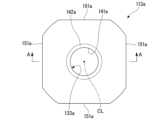
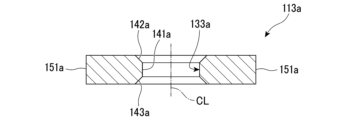
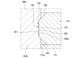
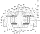
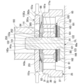
- FIG. 4 is a diagram showing the washer before assembly of the body valve of the first embodiment, and is a sectional view taken along the line AA in FIG. 3.
- FIG. 4 is a diagram showing the washer before assembly of the body valve of the first embodiment, and is a sectional view taken along the line AA in FIG. 3.
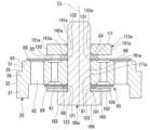
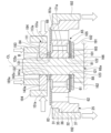
- FIG. 3 is a cross-sectional view taken along a cross section including the central axis CL, showing a state after the shaft insertion step and before the clamping step in the method for manufacturing the shock absorber and body valve of the first embodiment.
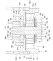
- FIG. 2 is a diagram illustrating a clamping step, a residual axial force applying step, and a pressing step in the method for manufacturing the shock absorber and body valve of the first embodiment, and is a cross-sectional view taken along a section including the center axis CL.
- FIG. 7 is a partial enlarged cross-sectional view of section B in FIG. 6 illustrating the state after the pressing step and before the caulking step in the method for manufacturing the shock absorber and body valve of the first embodiment.
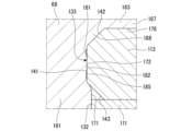
- FIG. 8 is a diagram showing essential parts of the body valve of the first embodiment, and is a partially enlarged cross-sectional view corresponding to FIG. 7.
- FIG. 4 is a diagram illustrating a clamping step, a residual axial force applying step, and a pressing step in Modification 1 of the method for manufacturing the shock absorber and body valve of the first embodiment, and is a cross-sectional view taken along a cross section including the central axis CL. It is. It is a side view which shows the clamp member used in the modification 1 of the manufacturing method of the shock absorber and body valve of the same 1st Embodiment. It is a top view which shows the washer before assembly of the modification 2 of the body valve of the same 1st Embodiment.
- FIG. 4 is a diagram illustrating a clamping step, a residual axial force applying step, and a pressing step in Modification 1 of the method for manufacturing the shock absorber and body valve of the first embodiment, and is a cross-sectional view taken along a cross section including the
- FIG. 12 is a cross-sectional view taken along the line CC in FIG. 11, showing a washer before assembly of Modification 2 of the body valve of the first embodiment. It is a top view which shows the washer before assembly of the modification 3 of the body valve of the same 1st Embodiment.
- FIG. 14 is a diagram showing a washer before assembly of Modification Example 3 of the body valve of the first embodiment, and is a sectional view taken along line DD in FIG. 13.
- FIG. 15 is a cross-sectional view corresponding to FIG. 14, showing a washer before assembly of modification 4 of the body valve of the first embodiment.
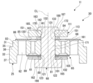
- FIG. 1 shows a buffer 11 of the first embodiment.
- the shock absorber 11 is a shock absorber used in a suspension device of a vehicle such as an automobile or a railway vehicle. Specifically, the shock absorber 11 is a shock absorber used in a strut type suspension of an automobile.
- the shock absorber 11 includes a cylinder 17 having an inner cylinder 15 and an outer cylinder 16.
- the inner cylinder 15 is cylindrical.
- the outer cylinder 16 has a cylindrical shape with a bottom.
- the outer cylinder 16 has a larger diameter than the inner cylinder 15 and is provided on the outer peripheral side of the inner cylinder 15. Therefore, the shock absorber 11 is a double-tube shock absorber.
- a reservoir chamber 18 between the outer cylinder 16 and the inner cylinder 15 is a reservoir chamber 18 (chamber).
- the outer cylinder 16 is an integrally molded product made of a single metal member.
- the outer cylinder 16 has a side wall part 21 and a bottom part 22.
- the side wall portion 21 is cylindrical.
- the bottom portion 22 is disc-shaped and closes one end of the side wall portion 21 in the axial direction.
- the outer cylinder 16 has an opening 23 on the opposite side of the side wall portion 21 from the bottom portion 22 .
- the shock absorber 11 includes a valve body 25 and a rod guide 26.
- the valve body 25 has an annular shape, is provided at one end of the inner cylinder 15 in the axial direction, and is placed on the bottom 22 of the outer cylinder 16.
- the rod guide 26 has an annular shape and is provided at the ends of the inner cylinder 15 and the outer cylinder 16 on the opposite side from the valve body 25 in the axial direction.
- the valve body 25 constitutes a body valve 30 (valve).
- the valve body 25 has a small outer diameter portion 31 and a large outer diameter portion 32 having a larger diameter than the small outer diameter portion 31 on the outer circumference.
- the rod guide 26 also has a small outer diameter portion 33 and a large outer diameter portion 34 having a larger diameter than the small outer diameter portion 33 on the outer circumference.
- One axial end of the inner cylinder 15 fits into the small outer diameter portion 31 of the valve body 25.
- the inner cylinder 15 is placed on the bottom 22 of the outer cylinder 16 via the valve body 25.
- the other axial end of the inner tube 15 fits into the small outer diameter portion 33 of the rod guide 26 .
- the rod guide 26 has a large outer diameter portion 32 that fits into the side wall portion 21 of the outer cylinder 16 . Therefore, the inner cylinder 15 is fitted into the side wall portion 21 of the outer cylinder 16 via the rod guide 26. In this state, the inner cylinder 15 is positioned in the radial direction with respect to the outer cylinder 16.
- the valve body 25 has a partition 36 and a leg 37.
- the partition part 36 is in the shape of a perforated disk.
- the partitioning portion 36 is formed with a portion on the side of the small outer diameter portion 31 in the axial direction of the large outer diameter portion 32 and a small outer diameter portion 31 .
- the leg portions 37 protrude from the outer peripheral side of the partition portion 36 along the axial direction of the partition portion 36.
- the leg portion 37 is annular.
- the leg portion 37 is formed with a portion opposite to the small outer diameter portion 31 in the axial direction of the large outer diameter portion 32 .
- a passage groove 38 is formed in the leg portion 37 at a portion opposite to the partition portion 36 in the axial direction.
- the passage groove 38 passes through the leg portion 37 in the radial direction of the leg portion 37 .
- a plurality of passage grooves 38 having the same shape are provided in the leg portion 37 at equal intervals in the circumferential direction thereof.
- the leg portions 37 of the valve body 25 abut against the bottom portion 22 of the outer cylinder 16 .
- the valve body 25 and the bottom 22 of the outer cylinder 16 communicate with each other via the passage groove 38 between the inner cylinder 15 and the outer cylinder 16 .
- a reservoir chamber 18 is formed between the valve body 25 and the bottom portion 22, as is the case between the inner cylinder 15 and the outer cylinder 16.
- the shock absorber 11 has a closing member 41.
- the closing member 41 has an annular shape and is provided on the opposite side of the rod guide 26 from the bottom 22 .
- the closing member 41 is fitted into the inner peripheral portion of the side wall portion 21 of the outer cylinder 16 .
- a locking portion 43 is formed at an end of the side wall portion 21 opposite to the bottom portion 22 in the axial direction.
- the locking portion 43 is formed by plastically deforming the cylindrical side wall portion 21 radially inward by caulking such as curling.
- the closing member 41 is held between the locking portion 43 and the rod guide 26.
- the closing member 41 closes the opening 23 of the outer cylinder 16, and is specifically an oil seal.
- the shock absorber 11 has a piston 45.
- a sliding member 46 made of synthetic resin is attached to the outer periphery of the piston 45.
- the piston 45 is slidably provided in the inner tube 15 of the cylinder 17 via this sliding member 46 .
- the piston 45 defines the inside of the inner cylinder 15 into two chambers, a first chamber 48 and a second chamber 49 (chamber).
- the first chamber 48 is provided between the piston 45 and the rod guide 26 within the inner cylinder 15.
- the second chamber 49 is provided between the piston 45 within the inner cylinder 15 and the valve body 25.
- the second chamber 49 is defined from the reservoir chamber 18 by the valve body 25 .
- the valve body 25 defines the inside of the cylinder 17 into two chambers, the second chamber 49 and the reservoir chamber 18.
- a first chamber 48 and a second chamber 49 are filled with oil L as a working fluid. Further, in the cylinder 17, a reservoir chamber 18 is filled with gas G and oil L as working fluid.
- the shock absorber 11 has a rod 50.
- the rod 50 has a main shaft portion 51 and a mounting shaft portion 52.
- the attachment shaft portion 52 has an outer diameter smaller than the outer diameter of the main shaft portion 51.
- the attachment shaft portion 52 is provided at one end of the main shaft portion 51 in the axial direction.
- the rod 50 has a mounting shaft portion 52 at one end in the axial direction connected to the piston 45, and a main shaft portion 51 at the other end in the axial direction extending outside from the outer cylinder 16 of the cylinder 17 through the opening 23.
- a piston 45 is connected to a mounting shaft portion 52 of the rod 50 by a nut 53.
- the main shaft portion 51 of the rod 50 passes through the rod guide 26 and the closing member 41 and extends from the inner tube 15 and the outer tube 16 to the outside.
- the main shaft portion 51 of the rod 50 is guided by the rod guide 26 and moves in the axial direction with respect to the inner cylinder 15 and the outer cylinder 16 together with the piston 45.
- the closing member 41 closes the space between the opening 23 of the outer cylinder 16 and the rod 50 to prevent the oil L in the inner cylinder 15 and the gas G and oil L in the reservoir chamber 18 from leaking to the outside. to regulate.
- a passage 55 and a passage 56 are formed in the piston 45 and extend through the piston 45 in the axial direction.
- the passages 55 and 56 allow the first chamber 48 and the second chamber 49 to communicate with each other.
- the passages 55 and 56 are passages through which the oil L flows.
- the shock absorber 11 has a disc valve 57 and a disc valve 58.
- the disc valve 57 has an annular shape, and is provided on the opposite side of the piston 45 from the bottom 22 in the axial direction.
- the disc valve 57 closes the passage 55 by coming into contact with the piston 45.
- the passage 55 is always open to the second chamber 49.
- the disc valve 58 has an annular shape and is provided on the bottom 22 side of the piston 45 in the axial direction.
- the disc valve 58 closes the passage 56 by coming into contact with the piston 45. Passage 56 is always open to first chamber 48 .
- the disc valves 57 and 58 are connected to the mounting shaft portion 52 of the rod 50 together with the piston 45.
- the direction in which the rod 50 increases the amount of penetration into the inner cylinder 15 and outer cylinder 16, that is, into the cylinder 17, is the contraction side in which the overall length of the shock absorber 11 is shortened.
- the disc valve 57 closes the passage 55 when the rod 50 moves to the contraction side and the piston 45 moves in a direction to narrow the second chamber 49 so that the pressure in the second chamber 49 becomes higher than the pressure in the first chamber 48 by a predetermined value or more. open. As a result, the oil L in the second chamber 49 flows into the first chamber 48 via the passage 55.
- the disc valve 57 is a damping valve that generates damping force at that time.
- a fixed orifice (not shown) is formed in at least one of the piston 45 and the disc valve 57. This fixed orifice allows the second chamber 49 and the first chamber 48 to communicate with each other via the passage 55 even when the disc valve 57 is in the state where the passage 55 is most closed.
- the direction in which the rod 50 increases the amount of protrusion from the inner cylinder 15 and the outer cylinder 16, that is, from the cylinder 17, is the extension side in which the entire length of the shock absorber 11 is increased.
- the disc valve 58 opens the passage 56 when the rod 50 moves to the extension side and the piston 45 moves in a direction to narrow the first chamber 48 so that the pressure in the first chamber 48 becomes higher than the pressure in the second chamber 49 by a predetermined value or more. open. As a result, the oil L in the first chamber 48 flows into the second chamber 49 via the passage 56.
- the disc valve 58 is a damping valve that generates damping force at that time.
- a fixed orifice (not shown) is formed in at least one of the piston 45 and the disc valve 58. This fixed orifice allows communication between the first chamber 48 and the second chamber 49 via the passage 56 even when the disc valve 58 is in the state where the passage 56 is most closed.
- the valve body 25 has a passage 61 and a passage 62 (working fluid passage) at the location of the partition 36.
- the passages 61 and 62 penetrate the partition 36 in the axial direction of the partition 36.
- the passages 61 and 62 allow the second chamber 49 and the reservoir chamber 18 to communicate with each other.
- the oil liquid L flows through the passages 61 and 62.
- the body valve 30 includes a disc valve 65, a disc valve 66 (valve member), and a pin member 68.
- the disc valve 65 is provided on the bottom 22 side of the valve body 25 in the axial direction.
- the disc valve 65 has an annular shape and closes the passage 61 by coming into contact with the valve body 25.
- the disc valve 66 is provided on the opposite side of the valve body 25 from the bottom 22 in the axial direction.
- the disc valve 66 has an annular shape and closes the passage 62 by coming into contact with the valve body 25.
- the pin member 68 connects and integrates the disc valves 65 and 66 with the valve body 25.
- the body valve 30 composed of the valve body 25, disc valves 65, 66, pin member 68, etc. defines the cylinder 17 into two chambers, a second chamber 49 and a reservoir chamber 18.
- the passage 61 is always in communication with the second chamber 49, and the passage 62 is always in communication with the reservoir chamber 18.
- the shock absorber 11 closes the body valve 30.
- the disc valve 65 will open the passage 61.
- the oil L in the second chamber 49 flows into the reservoir chamber 18 via the passage 61.
- the disc valve 65 generates a damping force.
- Disc valve 65 is a damping valve.
- the disc valve 66 of the body valve 30 closes. will open the passage 62.
- the oil L in the reservoir chamber 18 flows into the second chamber 49 via the passage 62.
- the disc valve 66 allows the oil L to flow from the reservoir chamber 18 into the second chamber 49 without substantially generating damping force.
- Disc valve 66 is a suction valve.
- a locking member 71 is fixed to the rod 50 between the piston 45 and the rod guide 26.
- a buffer member 72 is provided on the rod 50 between the locking member 71 and the rod guide 26 . The buffer member 72 is in contact with the locking member 71. When the rod 50 moves to a predetermined position on the extension side, the buffer member 72 comes into contact with the rod guide 26 and cushions the impact.
- the valve body 25 is made of metal.
- the valve body 25 is in the shape of a disc with holes.
- an inner circumferential surface 81 shown in FIG. 2 located at the center in the radial direction is a cylindrical surface.
- the valve body 25 has a partition portion 36 including a main body portion 83 , a fixed seat portion 84 , an inner seat portion 85 , an outer seat portion 86 , a fixed seat portion 88 , and a seat portion 89 .
- the main body portion 83 has a circular plate shape with holes. An axially intermediate portion of the inner circumferential surface 81 is disposed in the main body portion 83 .
- the fixed seat part 84, the inner seat part 85, and the outer seat part 86 are all provided on the side opposite to the leg part 37 in the axial direction of the main body part 83.
- the fixed seat portion 84 has an annular shape that surrounds the inner circumferential surface 81 on the outside in the radial direction of the inner circumferential surface 81 .
- the fixed seat portion 84 protrudes from the main body portion 83 along the axial direction of the main body portion 83 on the side opposite to the leg portions 37 .
- the inner seat portion 85 has an annular shape that surrounds the fixed seat portion 84 on the outside of the main body portion 83 in the radial direction.
- the inner seat portion 85 is spaced apart from the fixed seat portion 84 in the radial direction of the main body portion 83 .
- the inner seat portion 85 protrudes from the main body portion 83 along the axial direction of the main body portion 83 on the opposite side to the leg portions 37 .
- the outer seat portion 86 has an annular shape that surrounds the inner seat portion 85 on the outside of the main body portion 83 in the radial direction.
- the outer seat portion 86 is spaced apart from the inner seat portion 85 in the radial direction of the main body portion 83 .
- the outer sheet portion 86 protrudes from the main body portion 83 along the axial direction of the main body portion 83 on the opposite side to the leg portions 37 .
- the fixed seat portion 84, the inner seat portion 85, and the outer seat portion 86 have their protruding tip surfaces aligned in height with each other.
- the fixed seat portion 88 and the seat portion 89 are both provided on the side opposite to the fixed seat portion 84, the inner seat portion 85, and the outer seat portion 86 in the axial direction of the main body portion 83.
- the fixed seat portion 88 has an annular shape that surrounds the inner circumferential surface 81 on the outside in the radial direction of the inner circumferential surface 81 .
- the fixed seat portion 88 protrudes from the main body portion 83 along the axial direction of the main body portion 83 on the opposite side to the fixed seat portion 84 .
- the seat portion 89 has an annular shape that surrounds the fixed seat portion 88 on the outside of the main body portion 83 in the radial direction.
- the seat portion 89 is spaced apart from the fixed seat portion 88 in the radial direction of the main body portion 83.
- the seat portion 89 protrudes from the main body portion 83 along the axial direction of the main body portion 83 on the side opposite to the inner seat portion 85 .
- the height position of the protruding tip surface of the seat portion 89 is slightly higher than the height position of the protruding tip surface of the fixed seat portion 88.
- the passage 61 has one end opening between the fixed seat part 84 and the inner seat part 85 and the other end opening between the fixed seat part 88 and the seat part 89.
- a plurality of passages 61 are formed in the main body portion 83 at equal intervals in the circumferential direction of the valve body 25 .
- the passage 62 has one end opened between the inner seat part 85 and the outer seat part 86, and the other end opened between the seat part 89 and the leg part 37.
- a plurality of passages 62 are formed in the main body portion 83 at equal intervals in the circumferential direction of the valve body 25 .
- the passage 61 is located between the inner peripheral surface 81 and the passage 62.
- the body valve 30 includes a disk valve 65, a disk 101, and a restraining disk 102 on the leg 37 side in the axial direction of the partition 36, in this order from the partition 36 side in the axial direction.
- the disk valve 65 is made up of a plurality of disks 105, specifically two disks 105 having the same shape.
- the disk 101, the suppression disk 102, and the plurality of disks 105 are all made of metal, and each has a circular flat plate shape with holes, that is, a disk shape.
- the outer diameter of the disk 105 is slightly larger than the outer diameter of the seat portion 89.
- the disk 105 has an inner circumferential surface 121 located at the center in the radial direction that is a cylindrical surface.
- the disc valve 65 among the plurality of discs 105, the disc 105 that is closest to the partition part 36 in the axial direction comes into contact with the fixed seat part 88 and the seat part 89.
- the disc valve 65 opens and closes the passage 61 when the disc 105 separates from and comes into contact with the seat portion 89.
- the outer diameter of the disk 101 is smaller than the outer diameter of the disk 105.
- the disk 101 has an inner circumferential surface 122 located at the center in the radial direction that is a cylindrical surface.
- the outer diameter of the suppression disk 102 is larger than the outer diameter of the disk 101 and slightly smaller than the outer diameter of the disk 105.
- the suppression disk 102 has an inner circumferential surface 123 located at the center in the radial direction that is a cylindrical surface. Suppression disk 102 is thicker than disk 105. Restraining disc 102 is more rigid than disc 105.
- the body valve 30 has a disk valve 66, a disk 111, and a washer 113 (regulating member) on the side opposite to the legs 37 in the axial direction of the partition 36, in this order from the partition 36 side in the axial direction.
- the disk valve 66 and the disk 111 are both made of metal, and both have a circular flat plate shape with holes, that is, a disk shape.
- the outer diameter of the disc valve 66 is slightly larger than the outer diameter of the outer seat portion 86.
- a passage hole 130 is formed in the disc valve 66 and passes through the disc valve 66 in the axial direction of the disc valve 66.
- a plurality of passage holes 130 are formed in the disc valve 66 at equal intervals in the circumferential direction of the disc valve 66.
- the disc valve 66 has an inner circumferential surface 131 located at the center in the radial direction that is a cylindrical surface. The disc valve 66 abuts the fixed seat portion 84 , the inner seat portion 85 and the outer seat portion 86 .
- the plurality of passage holes 130 are arranged between the fixed seat part 84 and the inner seat part 85 in the radial direction of the disc valve 66.
- the disc valve 66 opens and closes the passage 62 by moving away from and abutting the outer seat portion 86 .
- the outer diameter of the disk 111 is smaller than the outer diameter of the disk valve 66.
- the disk 111 has an inner circumferential surface 132 located at the center in the radial direction that is a cylindrical surface.
- the diameter of the inner circumferential surface 81 of the valve body 25, the diameter of the inner circumferential surface 121 of the disk 105, the diameter of the inner circumferential surface 122 of the disk 101, the diameter of the inner circumferential surface 123 of the suppression disk 102, the inner circumferential surface 131 of the disk valve 66. and the diameter of the inner circumferential surface 132 of the disk 111 are the same.
- FIG. 3 and 4 show the washer 113a before being assembled to the body valve 30 shown in FIG. 2.
- this washer 113a is assembled to the body valve 30, it is plastically deformed to become the washer 113 shown in FIG.
- the washer 113a has a rectangular flat plate shape with holes.
- the washer 113a is made of metal.
- the washer 113a has an inner circumferential surface 133a in the center that is circular when viewed from the thickness direction of the washer 113a.
- the inner circumferential surface 133a has a small diameter portion 141a, a large diameter portion 142a, and a large diameter portion 143a.
- the small diameter portion 141a is provided at the center of the inner peripheral surface 133a in the thickness direction of the washer 113a.
- the small diameter portion 141a has a cylindrical surface.
- the central axis of the small diameter portion 141a is along the thickness direction of the washer 113a.
- the diameter of the small diameter portion 141a is equal to the diameter of the inner peripheral surface 81 of the valve body 25, as shown in FIG.
- the large diameter portion 142a expands in diameter from one end in the axial direction of the small diameter portion 141a in a direction away from the small diameter portion 141a in the axial direction.
- the large diameter portion 142a is a tapered surface.
- the large diameter portion 143a expands in diameter from the end opposite to the large diameter portion 142a in the axial direction of the small diameter portion 141a, and spreads away from the small diameter portion 141a in the axial direction.
- the large diameter portion 143a is a tapered surface.
- the small diameter portion 141a and the large diameter portions 142a, 143a have their central axes aligned.
- This central axis is the central axis of the inner peripheral surface 133a.
- Inner peripheral surface 133a is located at the center in the radial direction of washer 113a.
- the center axis of the inner peripheral surface 133a coincides with the center axis of the washer 113a.
- the axial direction of washer 113a coincides with the thickness direction of washer 113a.
- the small diameter portion 141a is located at the center of the washer 113a in the axial direction.
- the inner periphery of the washer 113a is provided with a small diameter portion 141a, and large diameter portions 142a and 143a that have a larger diameter than the small diameter portion 141a and are provided at different positions in the axial direction of the washer 113a. It is being
- a pressing surface 151a is formed on the outer periphery of the washer 113a.
- the pressing surface 151a is a plane extending perpendicularly to the radial direction of the washer 113a.
- the washer 113a has a plurality of pressing surfaces 151a, specifically four, having the same shape and are formed at equal intervals in the circumferential direction.
- the four pressing surfaces 151a are at the same distance from the central axis of the washer 113a.
- the pressing surfaces 151a and 151a that are adjacent to each other in the circumferential direction of the washer 113a are perpendicular to each other.
- the washer 113a has mirror symmetry in the axial direction. In other words, the washer 113a has the same shape even if it is reversed in the axial direction.
- the washer 113a has a wall thickness that is thicker than that of the disc valve 66. That is, the washer 113a is thicker than the disc valve 66.
- the washer 113a has higher rigidity than the disc valve 66.
- FIG. 5 shows the pin member 68a of the pin member 68 shown in FIG. 2 in a state before caulking. This pin member 68a becomes the pin member 68 shown in FIG. 2 by being caulked and plastically deformed.
- the pin member 68a has a shaft portion 161a and a collar portion 162.
- the pin member 68a is made of metal.
- the shaft portion 161a has a cylindrical shape.
- the outer peripheral surface 171a of the shaft portion 161a is a cylindrical surface.
- the flange portion 162 extends outward in the radial direction of the shaft portion 161a from one end of the shaft portion 161a in the axial direction.
- the outer peripheral surface of the collar portion 162 is a cylindrical surface.
- An end surface 165 of the flange portion 162 on the side from which the shaft portion 161a extends in the axial direction is a plane that extends perpendicularly to the central axis of the shaft portion 161a.
- an end surface 166 opposite to the end surface 165 in the axial direction is a plane parallel to the end surface 165.
- the inner circumferential surface 81 of the valve body 25 the inner circumferential surface 131 of the disk valve 66, the inner circumferential surface 132 of the disk 111, and the inner circumferential surface 133a of the washer 113a.
- the shaft part 161a of the pin member 68a is arranged on the inner periphery of the restraining disk 102, the disk 101, the plurality of disks 105, the valve body 25, the disk valve 66, the disk 111, and the washer 113a.
- the restraining disk 102, the disk 101, the plurality of disks 105, the valve body 25, the disk valve 66, the disk 111, and the washer 113a are placed on the end surface 165 of the flange 162 in this order.
- the valve body 25 is oriented such that the leg portion 37 projects from the partition portion 36 toward the flange portion 162 in the axial direction.
- a clamping process is performed.
- the pin member 68a is placed on the mounting table 191 of the caulking device with the end surface 166 of the flange 162 in contact with the pin member 68a.
- a plurality of hook-shaped clamp members 192 of the crimping device are brought into contact with the small outer diameter section 31 and the large outer diameter section 32 of the valve body 25 from the radially outer side at the same time.
- the plurality of clamp members 192 are hook-shaped and engage with the stepped portion 35 between the large outer diameter portion 32 and the small outer diameter portion 31 of the valve body 25 .
- the crimping device pulls the plurality of clamp members 192 downward to clamp the valve body 25, the plurality of disks 105, the disk 101, the restraining disk 102, and the flange portion 162 of the pin member 68a to the mounting table 191.
- This state is the clamping state of the crimping device.
- the cylindrical axial force applying member 193 of the crimping device applies pressure to the end surface of the washer 113a on the side opposite to the valve body 25 in the axial direction toward the valve body 25 side.
- the flange 162, the restraining disk 102, the disk 101, the plurality of disks 105, the valve body 25, the disk valve 66, the disk 111, and the washer 113a are clamped in the axial direction by the mounting table 191 and the axial force applying member 193. be done.
- the crimping device applies residual axial force to the restraining disk 102, the disk 101, the plurality of disks 105, the valve body 25, the disk valve 66, the disk 111, and the washer 113a.
- This state is the state in which the residual axial force is applied to the crimping device.
- a portion of the shaft portion 161a of the pin member 68a that faces the washer 113a in the radial direction by aligning the axial position of the shaft portion 161a with the washer 113a becomes a facing portion 185a.
- a pressing process is performed using a crimping device while maintaining the clamped state and the state in which residual axial force is applied. Note that this pressing step can be performed in parallel with the residual axial force applying step, in other words, it is also possible to perform it simultaneously with the residual axial force applying step.
- the pressing portion 194 of the crimping device presses the washer 113a radially inward toward the shaft portion 161a of the pin member 68a.
- a plurality of pressing portions 194 are provided at equal intervals at four locations, the same number as the pressing surfaces 151a, so as to surround the washer 113a on the outside in the radial direction of the washer 113a. ing. Then, the four pressing parts 194 are simultaneously moved inward along the radial direction of the washer 113a and the shaft part 161a.
- the washer 113a is arranged so that each pressing surface 151a spreads perpendicularly to the advancing direction of the corresponding pressing portion 194 on a one-to-one basis. Then, the washer 113a is simultaneously pressed radially inward by the four pressing portions 194 to plastically deform the washer 113a and the shaft portion 161a radially inward. In other words, the washer 113a is pushed horizontally from four directions until it bites into the shaft portion 161a. This state is the pressing state of the crimping device.
- the pin member 68a shown in FIGS. 5 and 6 becomes the pin member 68b shown in FIG. 7 by performing the pressing process.
- the pin member 68b has a shaft portion 161b having an outer circumferential surface 171b and a concave portion 172.
- the outer circumferential surface 171b is a cylindrical surface having the same diameter as the outer circumferential surface 171a shown in FIGS. 5 and 6 before the pressing process.
- the concave portion 172 shown in FIG. 7 is formed by a pressing process.
- the concave portion 172 is recessed inward in the radial direction of the outer circumferential surface 171b from an intermediate position in the axial direction of the outer circumferential surface 171b.
- the outer diameter of the portion of the shaft portion 161b of the pin member 68b where the concave portion 172 is formed is smaller than the outer diameter of the portion of the pin member 68b other than the concave portion 172 in the axial direction.
- the distance from the central axis of the outer peripheral surface 171b of the shaft portion 161b of the pin member 68b to the recessed portion 172 is smaller than the radius of the outer peripheral surface 171b other than the recessed portion 172 of the pin member 68b.
- a plurality of concave portions 172, specifically four concave portions 172, are formed in the shaft portion 161b at intervals in the circumferential direction of the shaft portion 161b.
- the washer 113a shown in FIGS. 5 and 6 is plastically deformed by performing the pressing process and becomes the washer 113 shown in FIG. 7.
- an inner circumferential surface 133a shown in FIGS. 5 and 6 before plastic deformation becomes an inner circumferential surface 133 that enters the concave portion 172 of the shaft portion 161 after plastic deformation.
- the small diameter part 141a shown in FIGS. 5 and 6 becomes the small diameter part 141 shown in FIG. 7, and the large diameter part 142a shown in FIGS. 5 and 6 becomes the large diameter part 142 shown in FIG. Therefore, the large diameter portion 143a shown in FIGS. 5 and 6 becomes the large diameter portion 143 shown in FIG. 7.
- the small diameter portion 141 is provided at the center of the inner peripheral surface 133 in the thickness direction of the washer 113. In other words, the small diameter portion 141 is located at the center of the washer 113 in the axial direction. Among the small diameter portions 141, the distance from the center axis of the washer 113 in the radial direction to the minimum inner diameter portion 181 is smaller than the radius of the inner circumferential surface 81 of the valve body 25 shown in FIG. In the pressing step, a plurality of pressing surfaces 151a, specifically four pressing surfaces 151a shown in FIG. A plurality of holes, specifically four, are formed at intervals.
- the minimum inner diameter portion 181 of the small diameter portion 141 of the washer 113 forms the concave bottom surface 182 of the concave portion 172 of the pin member 68b. Therefore, even after the pressing step, the minimum inner diameter portion 181 of the small diameter portion 141 of the washer 113 contacts the concave bottom surface 182.
- the radial gap between the washer 113 and the pin member 68b at the minimum inner diameter portion 181 is as shown in FIG. This is smaller than the radial gap between the valve body 25 and the pin member 68 shown.
- Each of the pressing surfaces 151a of the washer 113a shown in FIGS. 3 to 6 becomes the pressing surface 151 of the washer 113 shown in FIG. 2 through the pressing process.
- the large diameter portion 142 of the washer 113 expands in diameter from one end of the small diameter portion 141 in the axial direction of the washer 113 and spreads away from it in the axial direction of the washer 113.
- the large diameter portion 142 has a tapered shape.
- the large diameter portion 143 expands in diameter from the opposite end of the small diameter portion 141 from the large diameter portion 142 in the axial direction of the washer 113 and spreads apart in the axial direction of the washer 113.
- the large diameter portion 143 has a tapered shape.
- the concave portion 172 of the shaft portion 161b is aligned with the inner peripheral surface 133 of the washer 113 in the axial direction of the shaft portion 161b, and faces the inner peripheral surface 133 of the washer 113 in the radial direction.
- the pin member 68b has a facing portion 185b that is aligned with the washer 113 in the axial direction of the pin member 68b and faces the pin member 68b in the radial direction.
- the opposing portion 185b is configured by forming a concave portion 172 shown in FIG. 7 on the opposing portion 185a of the shaft portion 161a shown in FIG.
- a concave portion 172 is provided in the opposing portion 185b of the pin member 68b.
- the pin member 68b has an outer diameter at the position of the concave portion 172 of the opposing portion 185b of the shaft portion 161b that is larger than an outer diameter of the outer circumferential surface 171b at a portion other than the opposing portion 185b in the axial direction of the shaft portion 161b of the pin member 68b. It's getting smaller.
- the concave portion 172 may be formed in an annular shape over the entire circumference of the opposing portion 185b.
- the small diameter portion 141 enters the concave portion 172 over the entire circumference and comes into contact with the concave bottom surface 182 of the concave portion 172 .
- the washer 113 has a large diameter portion 142 provided on the side opposite to the disk 111 in the axial direction of the washer 113, and has a tapered shape whose diameter increases from the small diameter portion 141 toward the side opposite to the disk 111. Further, the washer 113 has a large diameter portion 143 provided on the disk 111 side in the axial direction of the washer 113, and has a tapered shape whose diameter increases from the small diameter portion 141 toward the disk 111 side.
- the washer 113a is plastically deformed and becomes the washer 113.
- the pin member 68a shown in FIG. 6 has its axial position aligned with the washer 113a, and the opposing portion 185a facing in the radial direction is pressed by the washer 113a in the pressing process and is plastically deformed inward in the radial direction, as shown in FIG.
- the diameter of the concave bottom surface 182 which is the center in the axial direction of the shaft portion 161b, becomes the smallest due to the small diameter portion 141 of the washer 113 through the pressing process, and the diameter on both sides in the axial direction becomes the large diameter of the washer 113.
- the portions 142 and 143 deform to be larger than the small diameter portion 141.
- a crimping process is performed using a crimping device while maintaining the clamped state, residual axial force applied state, and pressed state.
- the crimping device uses a punch (not shown) to press the tip of the pin member 68b that protrudes beyond the washer 113 along the axial direction toward the mounting table 191 side, that is, the collar portion 162 side.
- a disk-shaped caulking portion 163 shown in FIG. 2 is formed. That is, in the crimping process, the tip portion of the shaft portion 161b shown in FIG. 7 on the opposite side to the flange portion 162 shown in FIGS. 5 and 6 in the axial direction is plastically deformed in the axial direction to expand radially outward.
- a planar abutting surface portion 178 is formed on the caulking portion 163, following the shape of the end surface of the washer 113 on the caulking portion 163 side in the axial direction.
- the pin member 68b shown in FIG. 7 is in a pressed state in which the opposing portion 185b of the shaft portion 161b is pressed radially inward by the washer 113 and is plastically deformed. .
- this pressed state when an axial load for caulking is applied to the pin member 68b in the caulking process, the flesh of the shaft portion 161b above the washer 113 is dammed by the washer 113, and the flesh of the shaft portion 161b located above the washer 113 is difficult to move. This makes it possible to form the caulked portion 163 shown in FIG. 2 while suppressing the radial expansion of the portion of the pin member 68b below the washer 113 in the axial direction.
- the pin member 68 is assembled into the restraining disk 102, the disk 101, the plurality of disks 105, and the valve body 25. , the disc valve 66, the disc 111, and the washer 113 are integrated. As a result, the body valve 30 is assembled.
- the body valve 30 in the assembled state will be described below.
- the flange portion 162 of the pin member 68 contacts the restraining disk 102 in surface contact at the end surface 165, and the caulking portion 163 of the pin member 68 contacts the washer 113 in surface contact at the contact surface portion 178, thereby restraining the body valve 30.
- the parts from the disk 102 to the washer 113 are held.
- the flange portion 162 and the caulking portion 163 of the pin member 68 move the restraining disk 102, the disk 101, the plurality of disks 105, the valve body 25, the disk valve 66, the disk 111, and the washer 113 in the axial direction. Clamp with residual axial force applied from both sides.
- the residual axial force applied to the suppression disk 102, the disk 101, the plurality of disks 105, the valve body 25, the disk valve 66, the disk 111, and the washer 113 in the residual axial force applying step described above is applied to the body valve 30. However, it remains.
- the shaft portion 161 of the pin member 68 has a shape having an outer circumferential surface 171 and a concave portion 172, as also shown in FIG.
- the outer circumferential surface 171 is a cylindrical surface having the same diameter as the outer circumferential surface 171a shown in FIGS. 5 and 6 before the pressing process and the outer circumferential surface 171b shown in FIG. 7 before the caulking process.
- the concave portion 172 is recessed inward from the outer circumferential surface 171 in the radial direction of the outer circumferential surface 171.
- the outer diameter of the portion of the pin member 68 where the recessed portion 172 is formed is smaller than the outer diameter of the portion of the pin member 68 other than the recessed portion 172 in the axial direction.
- the distance from the central axis of the outer peripheral surface 171 of the shaft portion 161 to the concave bottom surface 182 of the recessed portion 172 is smaller than the radius of the outer peripheral surface 171 of the shaft portion 161 other than the recessed portion 172.
- a plurality of concave portions 172 are formed in the shaft portion 161 at intervals in the circumferential direction of the shaft portion 161.
- the inner circumferential surface 133 of the washer 113 enters into and abuts the concave portion 172 of the shaft portion 161.
- the smallest inner diameter portion 181 of the small diameter portion 141 enters the recessed portion 172 and abuts against the recessed bottom surface 182 of the recessed portion 172 . Therefore, the radial gap between the shaft portion 161 of the pin member 68 and the minimum inner diameter portion 181 of the washer 113 is smaller than the radial gap between the valve body 25 and the shaft portion 161 shown in FIG. .
- the pin member 68 has a facing portion 185 that faces in the radial direction with the washer 113 and the pin member 68 aligned in the axial direction.
- a concave portion 172 is provided in the opposing portion 185 of the pin member 68 .
- the outer diameter of the opposing portion 185 of the pin member 68 at the position of the concave portion 172 is smaller than the outer diameter of the portion of the pin member 68 other than the opposing portion 185 in the axial direction.
- the caulking portion 163 of the pin member 68 has a push plate portion 187 and an extra wall portion 188.
- the push plate portion 187 has a flat plate shape and has a contact surface portion 178.
- the extra thickness portion 188 protrudes from the radially inner side of the contact surface portion 178 toward the large diameter portion 142 and is in contact with the large diameter portion 142 .
- the extra wall portion 188 is formed by the shaft portion 161b shown in FIG. 7 protruding so as to fill the gap between the shaft portion 161b and the large diameter portion 142 of the washer 113 through a caulking process.
- the concave portion 172 may be formed in an annular shape over the entire circumference of the opposing portion 185.
- the small diameter portion 141 enters the concave portion 172 over the entire circumference and comes into contact with the concave bottom surface 182 of the concave portion 172 .
- the washer 113 has a large diameter portion 142 provided on the caulking portion 163 side in the axial direction of the washer 113, and has a tapered shape whose diameter increases from the small diameter portion 141 toward this side. Further, the washer 113 has a large diameter portion 143 provided on the valve body 25 side in the axial direction of the washer 113, and has a tapered shape whose diameter increases from the small diameter portion 141a toward the valve body 25 side.
- the pin member 68 has a flange portion 162 shaped like a disk that extends outward in the radial direction of the shaft portion 161 from one end of the shaft portion 161 in the axial direction.
- An end surface 165 of the collar portion 162 is a plane that extends perpendicularly to the central axis of the outer circumferential surface 171 of the shaft portion 161 .
- a caulking portion 163 is provided at an end portion of the shaft portion 161 on the opposite side to the flange portion 162 in the axial direction.
- the caulking portion 163 has an outer diameter larger than the outer diameter of the shaft portion 161.
- an abutment surface portion 178 on the side of the collar portion 162 in the axial direction of the push plate portion 187 is a plane extending perpendicularly to the central axis of the outer circumferential surface 171 of the shaft portion 161.
- the pin member 68 has a flange portion 162 at one end in the axial direction and a caulked portion 163 at the other end.
- the pin member 68 has a shaft portion 161 that is connected to the inner circumferential surface 123 of the restraining disk 102, the inner circumferential surface 122 of the disk 101, the inner circumferential surface 121 of each of the plurality of disks 105, the inner circumferential surface 81 of the valve body 25, and the disk. It is arranged radially inside each of the inner circumferential surface 131 of the valve 66, the inner circumferential surface 132 of the disk 111, and the inner circumferential surface 133 of the washer 113.
- the pin member 68 is arranged on the inner periphery of the restraining disk 102, the disk 101, the plurality of disks 105, the partition 36 of the valve body 25, the disk valve 66, and the disk 111.
- the valve body 25 is oriented such that the leg portion 37 protrudes from the partition portion 36 in the opposite direction from the caulking portion 163 in the axial direction.
- the pin member 68 holds the restraining disk 102, the disk 101, the plurality of disks 105, the valve body 25, the disk valve 66, the disk 111, and the washer 113 from both sides in the axial direction between the flange portion 162 and the caulking portion 163. ing.
- the restraining disk 102, the disk 101, the plurality of disks 105, the valve body 25, the disk valve 66, the disk 111, the washer 113, and the pin member 68 are integrated.
- the pin member 68 integrates the restraining disk 102, the disk 101, the plurality of disks 105, the valve body 25, the disk valve 66, the disk 111, and the washer 113 in an axial direction of the pin member 68.
- the flange portion 162 contacts the restraining disk 102 in surface contact at the end surface 165
- the caulked portion 163 contacts the washer 113 in surface contact at the contact surface portion 178.
- the body valve 30 is of a rivet type in which a restraining disk 102, a disk 101, a plurality of disks 105, a valve body 25, a disk valve 66, a disk 111, and a washer 113 are integrally connected by a pin member 68 that is a rivet. ing.
- the pin member 68 has a flange portion 162 and a caulking portion 163 to absorb residual axial force from both sides in the stacking direction of the restraining disk 102, the disk 101, the plurality of disks 105, the valve body 25, the disk valve 66, the disk 111, and the washer 113. These are integrated in the axial direction by being applied and clamped.
- the body valve 30 assembled as described above is fitted into one end of the inner cylinder 15 in the axial direction at the small outer diameter portion 31 of the valve body 25. Can be assembled.
- the rod 50 moves to the contraction side, and the piston 45 moves in a direction to narrow the second chamber 49.
- the body valve 30 deforms so that the outer peripheral side of the disc valve 65 is separated from the valve body 25 in the axial direction.
- the disc valve 65 separates from the seat portion 89 shown in FIG. 2 and opens the passage 61.
- the oil L flows from the second chamber 49 shown in FIG. 1 to the reservoir chamber 18 shown in FIG. 1 through the passage hole 130 of the disc valve 66 shown in FIG. 2 and the passage 61 of the valve body 25.
- the suppression disk 102 shown in FIG. 2 suppresses deformation of the disk valve 65 provided between the valve body 25 and the disk valve 65 by coming into contact with the disk valve 65.
- the rod 50 shown in FIG. 1 moves to the extension side, and the piston 45 moves to the first chamber 48 side.
- the body valve 30 deforms so that the disk valve 66 axially separates the outer peripheral side from the valve body 25.
- the disc valve 66 will be unseated from the outer seat portion 86 shown in FIG. 2 to open the passageway 62.
- the oil L flows from the reservoir chamber 18 shown in FIG. 1 to the second chamber 49 shown in FIG. 1 through the passage 62 of the valve body 25.
- the disc valve 66 opens the passage 62 when the rod 50 moves to the extension side, and allows the oil L to flow from the reservoir chamber 18 to the second chamber 49 via the passage 62.
- the washer 113 shown in FIG. 2 suppresses deformation of the disc valve 66 provided between the valve body 25 and the disc valve 66 by coming into contact with the disc valve 66.
- a plurality of disc-shaped disc valves 66 may be provided one on top of the other.
- the plurality of disc valves 66 serve as expansion-side damping valves that generate a damping force when the oil L flows from the reservoir chamber 18 shown in FIG. 1 to the second chamber 49 through the passage 62. That is, the body valve 30 of the shock absorber 11 only needs to have at least one disk valve 66 that is a disk-shaped valve member.
- the valve body and the valve member are inserted into the valve body and the valve member by inserting a pin member having a flange on one side and caulking the other side of the pin member.
- a hydraulic shock absorber with an integrated structure is described. With such a structure in which the pin member is caulked, stable damping force characteristics may not be obtained. That is, during caulking, the flesh of the pin member moves toward the inner circumferential side of the valve member, pushing the valve member radially outward and deforming it. This results in variations in the damping force characteristics.
- the type that integrates the valve body and valve member by caulking a pin member requires fewer parts than the type that integrates the valve body and valve member with bolts and nuts, resulting in lower productivity and cost. It has an advantage in terms of
- the shock absorber 11 of the first embodiment includes a cylinder 17, a piston 45 provided in the cylinder 17, and a body valve 30 that defines the inside of the cylinder 17 into two first chambers 48 and a second chamber 49. ing.
- the body valve 30 includes a valve body 25, at least one disc-shaped disc valve 66, a washer 113, and a pin member 68.
- Valve body 25 has a passage 62 .
- Valve member 66 opens and closes passageway 62.
- the washer 113 is provided on the opposite side of the disc valve 66 from the valve body 25.
- the washer 113 is thicker than the disc valve 66.
- the pin member 68 is arranged on the inner periphery of the disc valve 66 and the washer 113.
- the pin member 68 has a flange portion 162 at one end and a caulking portion 163 at the other end. The pin member 68 aligns and integrates the valve body 25, disc valve 66, and washer 113 in the axial direction.
- the outer diameter of at least a portion of the opposing portion 185 of the pin member 68 that faces the washer 113 is smaller than the outer diameter of the portion of the pin member 68 other than the opposing portion 185 in the axial direction. ing.
- the radial gap between the washer 113 and the pin member 68 is smaller than the radial gap between the valve body 25 and the pin member 68.
- the body valve 30 of the shock absorber 11 having such a configuration has a residual axial force application step of applying residual axial force to the valve body 25 and the disc valve 66, and a pressing step of pressing the washer 113a toward the pin member 68a before caulking.
- the valve body 25, the disc valve 66, and the washer 113 are axially aligned and integrated using the pin member 68, including a caulking step of forming the caulked portion 163 by caulking.
- the body valve 30 of the shock absorber 11 is formed including the pressing process of pressing the washer 113a toward the pin member 68a, so when forming the caulking part 163 on the pin member 68b in the caulking process. , deformation of the portion of the pin member 68b closer to the disc valve 66 than the washer 113 can be suppressed by the washer 113 pressed toward the pin member 68b. As a result, deformation of the disc valve 66 can be suppressed. Therefore, the body valve 30 of the shock absorber 11 can obtain stable damping force characteristics without variations. That is, since the disc valve 66 is a suction valve, the body valve 30 can stably obtain the characteristic that the disc valve 66 opens without substantially generating damping force without variation.
- the body valve 30 of the shock absorber 11 is of a type in which the valve body 25, disc valve 66, etc. are integrated by caulking a pin member 68, so it is different from the type in which the valve body 25, disc valve 66, etc. are integrated with bolts and nuts. It requires fewer parts compared to other models, which is advantageous in terms of productivity and cost.
- the body valve 30 of the shock absorber 11 also includes a small diameter portion 141 and a large diameter portion provided on the inner periphery of the washer 113 and having a larger diameter than the small diameter portion 141 and at a different position in the axial direction from the small diameter portion 141. 142, 143 are provided. Therefore, in the pressing process, the pin member 68 can be effectively pressed with the washer 113. Therefore, deformation of the disc valve 66 can be effectively suppressed.
- the small diameter portion 141 is located at the center in the axial direction of the washer 113, the large diameter portion 142 is provided on the caulking portion 163 side in the axial direction of the washer 113, and the small diameter portion 141 is located at the center of the washer 113 in the axial direction. It has a tapered shape that expands in diameter from there toward the caulking portion 163. Therefore, the washer 113a can be smoothly pushed into the pin member 68a.
- the body valve 30 of the shock absorber 11 has a large diameter portion 143 provided on the valve body 25 side in the axial direction of the washer 113, and has a tapered shape whose diameter increases from the small diameter portion 141 toward the valve body 25. Therefore, the washer 113a can be smoothly pushed into the pin member 68a.
- the small diameter portion 141 is located at the center of the washer 113 in the axial direction
- the large diameter portion 142 is provided on the caulking portion 163 side in the axial direction of the washer 113
- the large diameter portion 143 is provided on the valve body 25 side in the axial direction of the washer 113. Therefore, the washer 113a before deformation of the washer 113 can be made into the same shape even if it is reversed in the axial direction. This makes it possible to eliminate the directionality in assembling the washer 113a to the pin member 68a. Therefore, it is not necessary to confirm the direction when assembling the washer 113a to the pin member 68a, and the assembling becomes easy.
- Modification 1> In modification example 1, instead of the plurality of hook-shaped clamp members 192 shown in FIG. 6, as shown in FIGS. A plurality of rectangular plate-shaped clamp members 192A that are in contact with each other are used. Then, the crimping device presses the plurality of clamp members 192A from above to clamp the valve body 25, the plurality of disks 105, the disk 101, the restraining disk 102, and the flange portion 162 of the pin member 68a to the mounting table 191.
- the plurality of clamp members 192A are formed with insertion holes 201 through which a jig (not shown) for pressing the pressing portion 194 is inserted. Also in this modification 1, after assembly, the same body valve 30 as in the first embodiment is obtained.
- This modification 1 also has the same effects as the first embodiment.
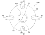
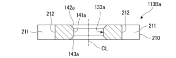
- the washer 113Ba has a disc shape, and a pressing groove 211 is formed on the outer circumference.
- the pressing groove 211 extends radially inward from the cylindrical outer peripheral surface 210 of the washer 113Ba.
- the pressing groove 211 passes through the washer 113Ba in the axial direction.
- the pressing groove 211 has an inner end 212 inside the washer 113Ba in the radial direction having a semi-cylindrical shape.
- a plurality of press grooves 211 having the same shape are formed in the washer 113Ba at equal intervals in the circumferential direction of the washer 113Ba, specifically, in four locations.
- the washer 113Ba has mirror symmetry in the axial direction.
- the washer 113Ba has a wall thickness greater than that of the disc valve 66 shown in FIG. That is, the washer 113Ba is thicker than the disc valve 66.
- the washer 113Ba has higher rigidity than the disc valve 66.
- This washer 113Ba is also pressed radially inward by four pressing parts (not shown) of the crimping device.
- the four pressing portions (not shown) each enter the corresponding pressing grooves 211 one-on-one and abut against the inner end portions 212 of the pressing grooves 211 .
- the four pressing portions (not shown) press the inner end portions 212 of the pressing grooves 211 that correspond to each other in a one-on-one manner inward in the radial direction of the washer 113Ba.
- the washer 113Ba also has an inner circumferential surface 133a having a small diameter portion 141a, a large diameter portion 142a, and a large diameter portion 143a.
- This inner circumferential surface 133a also becomes an inner circumferential surface 133 having the above-mentioned small diameter portion 141, large diameter portion 142, and large diameter portion 143 through a shaft insertion step, a clamping step, a residual axial force applying step, and a pressing step.
- a concave portion 172 is formed in the opposing portion 185b of the shaft portion 161b of the pin member 68b by the pressing process, and a caulked portion 163 is formed in the pin member 68 by the caulking process.
- the washer 113Ba has a disk shape with a cylindrical outer peripheral surface 210. Therefore, the washer formed from this washer 113Ba through a shaft insertion process, a clamping process, a residual axial force applying process, a pressing process, and a caulking process has a substantially disc shape, and the deformation of the disc valve 66 is well suppressed. can do.
- This second modification also has the same effects as the first embodiment.
- the pressing grooves 211 may be formed at three locations at equal intervals in the circumferential direction of the washer 113Ba, or may be formed at five or more locations.
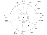
- the washer 113Ca has a disc-shaped disc-shaped part 221, a disc-shaped disc-shaped part 222, and a connecting part 223.
- the outer peripheral surface 225 of the disc-shaped portion 221 is a cylindrical surface.
- the outer peripheral surface 226 of the disc-shaped portion 222 is a cylindrical surface.
- the disk-shaped portion 221 and the disk-shaped portion 222 have the same shape.
- the disk-shaped portion 221 and the disk-shaped portion 222 are arranged coaxially.
- the connecting portion 223 is located between the disk-shaped portion 221 and the disk-shaped portion 222 to connect these disk-shaped portions 221 and 222.
- a pressing surface 151Ca is formed on the outer periphery of the connecting portion 223.
- the pressing surface 151Ca is a plane that extends perpendicularly to the radial direction of the disk-shaped portions 221 and 222.
- the washer 113Ca has a plurality of pressing surfaces 151Ca having the same shape, more specifically, four pressing surfaces 151Ca formed at equal intervals in the circumferential direction.
- the pressing surfaces 151Ca and 151Ca adjacent to each other in the circumferential direction of the washer 113a are perpendicular to each other.
- the washer 113Ca has mirror symmetry in the axial direction.
- each of the disk-shaped portion 221 and the disk-shaped portion 222 is thicker than the disk valve 66. That is, the washer 113Ca is thicker than the disc valve 66.
- the washer 113Ca has higher rigidity than the disc valve 66.
- This washer 113Ca is also pressed radially inward by four pressing parts (not shown) of the crimping device. At this time, each of the four pressing parts of the crimping device enters between the disc-shaped part 221 and the disc-shaped part 222, and abuts the corresponding pressing surface 151Ca on a one-to-one basis in the vertical direction. Each of the four pressing portions presses the corresponding pressing surface 151Ca inward in the radial direction of the washer 113Ca.
- the washer 113Ca also has an inner circumferential surface 133a having a small diameter portion 141a, a large diameter portion 142a, and a large diameter portion 143a. This inner circumferential surface 133a also becomes an inner circumferential surface 133 having the above-mentioned small diameter portion 141, large diameter portion 142, and large diameter portion 143 after the pressing process.
- the washer 113Ca also has a concave portion 172 formed in the opposing portion 185b of the shaft portion 161b of the pin member 68b through the shaft insertion step, clamping step, residual axial force applying step, and pressing step, and a caulking portion 163 on the shaft portion 161 through the crimping step. form.
- the washer 113Ca has a disk shape with cylindrical outer peripheral surfaces 225 and 226. Therefore, the washer formed from this washer 113Ca through a shaft insertion process, a clamping process, a residual axial force applying process, a pressing process, and a caulking process has a disk shape, and the deformation of the disk valve 66 is suppressed well. be able to.
- This third modification also has the same effects as the first embodiment.
- the pressing surface 151Ca may be formed into a cylindrical surface coaxial with the outer circumferential surfaces 225, 226 of the disc-shaped portions 221, 222.
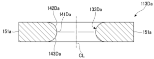
- the washer 113Da has an inner peripheral surface 133Da located at the center in the radial direction that is different from the inner peripheral surface 133a.
- Inner peripheral surface 133Da is circular when viewed from the thickness direction of washer 113Da.
- the inner circumferential surface 133Da has an arcuate cross section, specifically a semicircular cross section, in a plane extending in the thickness direction of the washer 113Da through the center of this circle.
- the inner peripheral surface 133Da has a small diameter portion 141Da at the center in the thickness direction of the washer 113Da.
- the inner peripheral surface 133Da has a large diameter portion 142Da on one side with respect to a small diameter portion 141Da in the thickness direction of the washer 113Da.
- the inner circumferential surface 133Da has a small diameter portion 141Da in the thickness direction of the washer 113Da, and a large diameter portion 143Da on the other side.
- the diameter of the small diameter portion 141Da is equal to the diameter of the inner peripheral surface 81 of the valve body 25.
- the large diameter portion 142Da increases in diameter from the small diameter portion 141Da, and spreads away from the washer 113Da to one side in the thickness direction.
- the large diameter portion 142Da is a curved surface.
- the large-diameter portion 143Da expands from the small-diameter portion 141Da to the other side in the thickness direction of the washer 113Da while increasing its diameter.
- the large diameter portion 143Da is a curved surface.
- the small diameter portion 141Da and the large diameter portions 142Da and 143Da have their central axes aligned.
- This central axis is the central axis of the inner peripheral surface 133Da.
- Inner peripheral surface 133Da is located at the center in the radial direction of washer 113Da.
- the center axis of the inner peripheral surface 133Da coincides with the center axis of the washer 113Da.
- the axial direction of washer 113Da coincides with the thickness direction of washer 113Da.
- the small diameter portion 141Da is located at the center of the washer 113Da in the axial direction.
- the inner periphery of the washer 113Da is provided with a small diameter portion 141Da, and large diameter portions 142Da and 143Da that have a larger diameter than the small diameter portion 141Da and are provided at different positions in the axial direction of the washer 113Da. It is being
- the washer 113Da has mirror symmetry in the axial direction.
- the washer 113Da has a wall thickness greater than that of the disc valve 66.
- the washer 113Da has higher rigidity than the disc valve 66.
- This washer 113Da is also pressed radially inward by the four pressing parts 194 of the crimping device.
- the four pressing portions 194 of the crimping device move in the vertical direction and come into contact with the corresponding pressing surfaces 151a on a one-to-one basis.
- Each of the four pressing portions 194 presses the corresponding pressing surface 151a inward in the radial direction of the washer 113Da.
- the washer 113Da forms a concave part in the pin member 68b by a pressing process, which has a different cross-sectional shape in a plane including the central axis of the shaft part 161b, compared to the concave part 172 of the shaft part 161b of the pin member 68b described above.
- the concave portion has an arcuate cross-sectional shape in a plane including the central axis of the shaft portion, following the shape of the inner circumferential surface 133Da of the washer 113Da.
- the outer diameter of the concave portion provided at the opposing portion of the shaft portion of the pin member is smaller than the outer diameter of the portion of the pin member other than the opposing portion in the axial direction.
- the minimum distance from the central axis of the shaft portion of the pin member to the recessed portion is smaller than the radius of the outer peripheral surface of the pin member other than the recessed portion.
- the washer (hereinafter referred to as the washer after the crimping process) formed through the shank insertion process, clamping process, residual axial force applying process, pressing process, and crimping process of the washer 113Da has an inner circumferential surface 133Da that is formed in this concave part. It becomes the inner peripheral surface that enters and comes into contact with.
- the small diameter part 141Da of the washer 113Da becomes the small diameter part
- the large diameter part 142Da of the washer 113Da becomes the large diameter part
- the large diameter part 143Da of the washer 113Da becomes the large diameter part.
- the small diameter portion of the washer after the crimping process is provided at the center of the inner peripheral surface in the thickness direction of the washer.
- the washer has a curved surface with one large diameter portion provided on the crimping portion 163 side in the axial direction of the washer and the diameter increasing from the small diameter portion toward this one side.
- the washer after the crimping process has a curved surface whose other large diameter portion is provided on the valve body 25 side in the axial direction of the washer, and whose diameter increases from the small diameter portion toward the valve body 25 side.
- the smallest inner diameter part of the small diameter part enters the concave part of the pin member and comes into contact with the concave bottom of the concave part. Therefore, the radial gap between the washer and the pin member at this minimum inner diameter portion is smaller than the radial gap between the valve body 25 and the pin member.
- This modification 4 also has the same effects as the first embodiment.
- the inner peripheral surface 133a of the washer 113Ba may have the same shape as the inner peripheral surface 133Da of the washer 113Da.
- the inner circumferential surface 133a of the washer 113Ca may have the same shape as the inner circumferential surface 133Da of the washer 113Da.
- the second embodiment will be described mainly based on FIGS. 16 and 17, focusing on the differences from the first embodiment. Note that parts that are common to those in the first embodiment are designated by the same names and symbols.
- the shock absorber 11E has a body valve 30E that is partially different from the body valve 30.
- the body valve 30E has a spring disc 251 on the opposite side of the disc 111 from the disc valve 66.
- Spring disc 251 is made of metal.
- the spring disk 251 has a base plate portion 252 and a spring plate portion 253.
- the substrate portion 252 has a circular flat plate shape with holes.
- An inner circumferential surface 255 of the base plate portion 252 is an inner circumferential surface of the spring disk 251.
- the diameter of this inner circumferential surface 255 is equal to the diameter of the inner circumferential surface 81 of the valve body 25.
- the spring plate portion 253 extends from the outer peripheral portion of the base plate portion 252 to the outside in the radial direction of the base plate portion 252 . As the spring plate portion 253 becomes farther away from the substrate portion 252 in the radial direction of the substrate portion 252, the spring plate portion 253 becomes further away from the substrate portion 252 in the axial direction of the substrate portion 252.
- a plurality of spring plate portions 253 having the same shape are provided on the spring disk 251 at equal intervals in the circumferential direction of the base plate portion 252.
- the base plate portion 252 abuts on the opposite side of the disk valve 66 in the axial direction of the disk 111.
- the plurality of spring plate portions 253 of the spring disk 251 come into contact with the disk valve 66 .
- the body valve 30E has a washer 113E (regulating member) on the opposite side of the disk 111 in the axial direction of the base plate portion 252 of the spring disk 251.
- the washer 113E is made of metal and has a circular plate shape with holes, that is, a disk shape.
- the washer 113E has a base plate portion 261 and an outer peripheral plate portion 262.
- the substrate portion 261 has a circular flat plate shape with holes.
- a through hole 265 is formed in the substrate portion 261 , passing through the substrate portion 261 in the axial direction of the substrate portion 261 .
- a plurality of through holes 265 are formed in the substrate portion 261 at equal intervals in the circumferential direction. In the radial direction of the base plate portion 261 , the through hole 265 is arranged outside the base plate portion 252 of the spring disk 251 .
- the outer circumferential plate portion 262 has an annular shape and is formed on the outside of the base plate portion 261 in the radial direction.
- the outer circumferential plate portion 262 has an annular shape surrounding the radially outer side of the base plate portion 261 .
- the outer circumferential plate portion 262 is shifted to one side in the axial direction with respect to the base plate portion 261.
- the outer peripheral plate portion 262 protrudes from the base plate portion 261 to one side in the axial direction.
- FIG. 17 shows the washer 113Ea before being assembled to the body valve 30E.
- this washer 113Ea is assembled to the body valve 30E, it is plastically deformed to become a washer 113E.
- the washer 113Ea has a base plate portion 261a and an outer peripheral plate portion 262a.
- the substrate portion 261a has a circular flat plate shape with holes.
- the outer circumferential plate portion 262a has an annular shape and is formed on the radially outer side of the base plate portion 261a.
- the outer circumferential plate portion 262a has an annular shape surrounding the radially outer side of the base plate portion 261a.
- the outer peripheral plate portion 262a is shifted to one side in the axial direction with respect to the base plate portion 261a.
- the outer peripheral plate portion 262a protrudes from the base plate portion 261a to one side in the axial direction.
- the washer 113Ea has an inner peripheral surface 133a similar to the washer 113a at the center of the base plate portion 261a, which is the center in the radial direction.
- the large diameter part 143a of the large diameter part 142a and the large diameter part 143a is arranged on the protruding side of the outer peripheral plate part 262a in the axial direction of the washer 113Ea.
- the washer 113Ea has a plurality of pressing surfaces 151a similar to the washer 113a on the outer periphery of the outer peripheral plate portion 262a.
- the washer 113Ea has a wall thickness greater than that of the disc valve 66. That is, the washer 113Ea is thicker than the disc valve 66. The washer 113Ea has higher rigidity than the disc valve 66.
- a shaft portion insertion step is performed.
- the inner circumferential surface 81 of the valve body 25, the inner circumferential surface 131 of the disc valve 66, the inner circumferential surface 132 of the disk 111, the inner circumferential surface 255 of the spring disk 251, and the inner circumferential surface 133a of the washer 113Ea in the radial direction. Insert them in this order.
- the restraining disk 102, the disk 101, the plurality of disks 105, the valve body 25, the disk valve 66, the disk 111, the spring disk 251, and the washer 113Ea are placed on the end surface 165 of the flange 162 in this order. .
- valve body 25 is oriented such that the leg portion 37 projects from the partition portion 36 toward the flange portion 162 in the axial direction.
- spring disk 251 is oriented such that the spring plate portion 253 extends from the base plate portion 252 toward the disk valve 66 and comes into contact with the disk valve 66 .
- the washer 113Ea is oriented such that the outer peripheral plate portion 262a protrudes from the base plate portion 261a toward the disc valve 66 in the axial direction of the base plate portion 261a.
- a residual axial force applying step is performed.
- the pin member 68a is placed on the mounting table 191 of the caulking device at the end surface 166 of the collar portion 162.
- the cylindrical axial force applying member 193 of the crimping device presses the end surface of the base plate portion 261 of the washer 113Ea on the side opposite to the valve body 25 in the axial direction toward the valve body 25 side.
- the flange 162, the restraining disk 102, the disk 101, the plurality of disks 105, the valve body 25, the disk valve 66, the disk 111, the spring disk 251, and the washer 113Ea are connected to the mounting table 191 and the axial force applying member 193.
- a pressing process is performed while maintaining the state of applying residual axial force.
- the pressing step is performed in parallel with the residual axial force applying step.
- the four pressing parts of the crimping device press the washer 113Ea radially inward toward the shaft part 161a of the pin member 68a to release the washer 113Ea and the shaft part, as in the first embodiment. 161a is plastically deformed radially inward. As a result, the washer 113Ea becomes the washer 113E, and the pin member 68a becomes the pin member 68b.
- a caulking process is performed while maintaining the residual axial force application state and the pressing state.
- the crimping device uses a punch (not shown) to press the tip of the pin member 68b that protrudes beyond the washer 113E along the axial direction toward the mounting table 191, that is, toward the collar 162, thereby crimping the pin member 68b.
- a disk-shaped caulking portion 163 shown in FIG. 16 is formed.
- the pin member 68a shown in FIG. 17 is changed to the pin member 68 shown in FIG. 16.
- the pin member 68 is assembled into the restraining disk 102, the disk 101, the plurality of disks 105, the valve body 25, and the disk valve. 66, the disk 111, the spring disk 251, and the washer 113E are integrated. As a result, the body valve 30E is assembled.
- an inner circumferential surface 133 similar to that of the washer 113 is formed on the inner circumference of the base plate portion 261 of the washer 113E. Further, in the assembled body valve 30E, the shaft portion 161 of the pin member 68 has the same shape as in the first embodiment.
- the second embodiment also has the same effects as the first embodiment.
- the washer 113Ea of the second embodiment it is also possible to change the inner circumferential surface 133Ea thereof in the same manner as the inner circumferential surface 133Da of the fourth modification.
- the washer 113Ea of the second embodiment can be changed to a shape having a plurality of pressing grooves 211 with the outer peripheral portion thereof being circular, as in the second modification.
- the inner circumferential surface 133a of the washer 113Ea may have the same shape as the inner circumferential surface 133Da of the fourth modification.
- the washer 113Ea of the second embodiment has a circular outer circumferential portion, and has a pair of disk-shaped portions and a connecting portion that connects the pair of disk-shaped portions. It is also possible to change the shape.
- the inner circumferential surface 133a of the washer 113Ea may have the same shape as the inner circumferential surface 133Da of the fourth modification.
- the present invention can also be applied to the case where the piston 45 is integrated into the rod 50.
- the mounting shaft portion 52 of the rod 50 is shaped similarly to the shaft portion 161 of the pin member 68. Then, in the shaft insertion step, the mounting shaft 52 of the rod 50 is inserted into the restraining disk 102, the disk 101, the plurality of disks 105, the valve body 25, the disk valve 66, the disk 111, and the washer 113 in this order.
- the restraining disk 102 is brought into contact with the end of the main shaft portion 51 on the mounting shaft portion 52 side in the axial direction.
- the washer 113 is pressurized toward the main shaft portion 51 along the axial direction of the rod 50 to apply residual axial force to the components from the restraining disk 102 to the washer 113.
- the washer 113 is pressed radially inward toward the mounting shaft portion 52 in a pressing step.
- a caulking step is performed to caulk the portion of the mounting shaft portion 52 that protrudes from the washer 113 to form a caulked portion.
- the parts from the restraining disk 102 to the washer 113 are integrated with the end of the main shaft part 51 on the side of the mounting shaft part 52 in the axial direction and the caulking part formed on the mounting shaft part 52.
- the leg portion 37, the small outer diameter portion 31, and the large outer diameter portion 32 are removed from the valve body 25, a sliding member is attached to the outer circumference of the valve body 25, and this sliding member is attached to the inner cylinder 15. Fit it to the inner circumference.
Landscapes
- Engineering & Computer Science (AREA)
- General Engineering & Computer Science (AREA)
- Mechanical Engineering (AREA)
- Fluid-Damping Devices (AREA)
Abstract
Description
本願は、2022年7月4日に、日本国に出願された特願2022-107764号に基づき優先権を主張し、その内容をここに援用する。
本発明に係る第1の態様は、
シリンダと、
前記シリンダ内に設けられたピストンと、
一端が前記ピストンと接続され、他端が前記シリンダから延出するロッドと、
前記シリンダ内を2室に画成するボデーバルブと、
を有し、
前記ボデーバルブが、
作動流体通路を有するバルブボディと、
前記作動流体通路を開閉する少なくとも一つのディスク状のバルブ部材と、
前記バルブ部材の前記バルブボディとは反対側に設けられて前記バルブ部材よりも厚肉である規制部材と、
前記バルブ部材および前記規制部材の内周に配置され、一端に鍔部を有すると共に他端にカシメ部を有し、前記バルブボディと前記バルブ部材と前記規制部材とを軸方向に並べて一体化するピン部材と、
を備え、
前記ピン部材の前記規制部材と対向する対向部の外径が、前記ピン部材の軸方向における前記対向部以外の部分よりも小さい、
緩衝器である。
シリンダと、
前記シリンダ内に設けられるピストンと、
前記シリンダ内を2室に画成するボデーバルブと、
を有し、
前記ボデーバルブが、
作動流体通路を有するバルブボディと、
前記作動流体通路を開閉する少なくとも一つのディスク状のバルブ部材と、
前記バルブ部材の前記バルブボディとは反対側に設けられて前記バルブ部材よりも厚肉である規制部材と、
前記バルブ部材および前記規制部材の内周に配置され、一端に鍔部を有すると共に他端にカシメ部を有し、前記バルブボディと前記バルブ部材と前記規制部材とを軸方向に並べて一体化するピン部材と、
を備える緩衝器の製造方法であって、
前記バルブボディおよび前記バルブ部材に残留軸力を与える残留軸力付与工程と、
前記規制部材を前記ピン部材に向けて押圧する押圧工程と、
かしめにより前記カシメ部を形成するカシメ工程と、
を含む。
緩衝器に用いられるバルブであって、
作動流体通路を有するバルブボディと、
前記作動流体通路を開閉する少なくとも一つのディスク状のバルブ部材と、
前記バルブ部材の前記バルブボディとは反対側に設けられて前記バルブ部材よりも厚肉である規制部材と、
前記バルブ部材および前記規制部材の内周に配置され、一端に鍔部を有すると共に他端にカシメ部を有し、前記バルブボディと前記バルブ部材と前記規制部材とを軸方向に並べて一体化するピン部材と、
を備え、
前記規制部材と前記ピン部材との間の隙間が、前記バルブボディと前記ピン部材との隙間よりも小さい。
緩衝器に用いられ、
作動流体通路を有するバルブボディと、
前記作動流体通路を開閉する少なくとも一つのディスク状のバルブ部材と、
前記バルブ部材の前記バルブボディとは反対側に設けられて前記バルブ部材よりも厚肉である規制部材と、
前記バルブ部材および前記規制部材の内周に配置され、一端に鍔部を有すると共に他端にカシメ部を有し、前記バルブボディと前記バルブ部材と前記規制部材とを軸方向に並べて一体化するピン部材と、
を有するバルブの製造方法であって、
前記バルブボディおよび前記バルブ部材に残留軸力を与える残留軸力付与工程と、
前記規制部材を前記ピン部材に向けて押圧する押圧工程と、
かしめにより前記カシメ部を形成するカシメ工程と、
を含む。
第1実施形態について、図1~図15を参照しつつ以下に説明する。なお、各図において符号CLを示したものは、緩衝器の中心軸線を示す。他の実施形態及び変形例についても同様である。
区画部36は、有孔円板状である。区画部36には、大径外径部32の軸方向における小径外径部31側の部分と小径外径部31とが形成されている。
ロッド50は、主軸部51と取付軸部52とを有している。
取付軸部52は、その外径が主軸部51の外径よりも小径である。取付軸部52は、主軸部51の軸方向の一端に設けられている。
ディスクバルブ57は、円環状であり、ピストン45の軸方向における底部22とは反対側に設けられている。ディスクバルブ57は、ピストン45に当接することで通路55を閉塞する。通路55は、第2室49に常時開口している。
ディスクバルブ57,58は、ピストン45とともにロッド50の取付軸部52に連結されている。
ディスクバルブ65は、バルブボディ25の軸方向における底部22側に設けられている。ディスクバルブ65は、円環状であり、バルブボディ25に当接することで通路61を閉塞する。
ピン部材68は、ディスクバルブ65,66をバルブボディ25に連結して一体化する。
本体部83は、有孔の円板状である。本体部83には、内周面81の軸方向の中間部分が配置されている。
固定シート部84は、内周面81を内周面81の径方向における外側で囲む円環状である。固定シート部84は、本体部83から本体部83の軸方向に沿って脚部37とは反対側に突出している。
バルブボディ25の軸方向において、固定シート部84、内側シート部85および外側シート部86は、互いに突出先端面の高さ位置を合わせている。
固定シート部88は、内周面81を内周面81の径方向における外側で囲む円環状である。固定シート部88は、本体部83から本体部83の軸方向に沿って固定シート部84とは反対側に突出している。
バルブボディ25の軸方向において、シート部89は、突出先端面の高さ位置が、固定シート部88の突出先端面の高さ位置よりも若干高くなっている。
バルブボディ25の径方向において、通路61は、内周面81と通路62との間にある。
ディスクバルブ65は、複数枚、具体的には2枚の同形状のディスク105からなっている。ディスク101、抑制ディスク102および複数枚のディスク105は、いずれも金属製であり、いずれも有孔の円形平板状すなわちディスク状である。
軸部161aは円柱状である。
軸部161aは、その外周面171aが円筒面である。
クランプ工程では、図6に示すように、カシメ装置の載置台191にピン部材68aを、鍔部162の端面166を当接させて載置させる。そして、カシメ装置の鉤型の複数のクランプ部材192をバルブボディ25の径方向外側から小径外径部31および大径外径部32に同時に当接させる。複数のクランプ部材192は、バルブボディ25の大径外径部32および小径外径部31の間の段部35に係合する鉤型である。そして、カシメ装置が、これら複数のクランプ部材192を下方に引いて、バルブボディ25、複数枚のディスク105、ディスク101、抑制ディスク102およびピン部材68aの鍔部162を載置台191にクランプする。この状態がカシメ装置のクランプ状態である。
残留軸力付与工程では、カシメ装置の円筒状の軸力付与部材193で、ワッシャ113aの軸方向におけるバルブボディ25とは反対側の端面をバルブボディ25側に加圧する。これにより、鍔部162、抑制ディスク102、ディスク101、複数枚のディスク105、バルブボディ25、ディスクバルブ66、ディスク111およびワッシャ113aが、載置台191と軸力付与部材193とで軸方向にクランプされる。言い換えれば、カシメ装置が、抑制ディスク102、ディスク101、複数枚のディスク105、バルブボディ25、ディスクバルブ66、ディスク111およびワッシャ113aに残留軸力を与える。この状態がカシメ装置の残留軸力付与状態である。ピン部材68aの軸部161aは、軸部161aの軸方向における位置をワッシャ113aと合わせてワッシャ113aと径方向に対向する部分が対向部185aとなる。
図3~図6に示すワッシャ113aの押圧面151aのそれぞれが、押圧工程によって図2に示すワッシャ113の押圧面151となる。
図6に示すピン部材68aは、その軸方向の位置をワッシャ113aと合わせて径方向に対向する対向部185aが、押圧工程によってワッシャ113aで押圧され径方向内方に塑性変形して図7に示す対向部185bとなる。対向部185bは、押圧工程によって、軸部161bの軸方向における中心部である凹底面182の径がワッシャ113の小径部141によって一番小さくなり、その軸方向両側の径がワッシャ113の大径部142,143によって、小径部141よりも拡大するように変形する。
カシメ工程では、カシメ装置が図示略のポンチで、ピン部材68bのワッシャ113よりも突出する先端部を軸方向に沿って載置台191側すなわち鍔部162側に加圧してかしめることにより、図2に示す円板状のカシメ部163を形成する。すなわち、カシメ工程では、図7に示す軸部161bの軸方向における図5および図6に示す鍔部162とは反対側の先端部を軸方向に塑性変形させることにより径方向外方に拡げて、図2に示すカシメ部163とする。その結果、図7に示すピン部材68bが、図2に示すピン部材68となる。カシメ工程では、カシメ部163に、ワッシャ113の軸方向のカシメ部163側の端面の形状に倣って平面状をなす当接面部178が形成される。
押板部187は、平板状であり、当接面部178を有している。
余肉部188は、当接面部178の径方向内側から大径部142側に突出して大径部142に当接している。余肉部188は、図7に示す軸部161bが、カシメ工程によってワッシャ113の大径部142との隙間を埋めるように突出することで形成される。
ピン部材68は、軸部161が、抑制ディスク102の内周面123、ディスク101の内周面122、複数枚のディスク105のそれぞれの内周面121、バルブボディ25の内周面81、ディスクバルブ66の内周面131、ディスク111の内周面132およびワッシャ113の内周面133のそれぞれの径方向内側に配置されている。言い換えれば、ピン部材68が、抑制ディスク102、ディスク101、複数枚のディスク105、バルブボディ25の区画部36、ディスクバルブ66およびディスク111の内周に配置されている。なお、このとき、バルブボディ25は、区画部36から脚部37が軸方向のカシメ部163とは反対側に突出する向きとされている。
変形例1では、図6に示す鉤型の複数のクランプ部材192に代えて、図9および図10に示すように、バルブボディ25の軸方向に沿って移動して上側から段部35に当接する矩形板状の複数のクランプ部材192Aを用いる。そして、カシメ装置が、複数のクランプ部材192Aを上から押して、バルブボディ25、複数枚のディスク105、ディスク101、抑制ディスク102およびピン部材68aの鍔部162を載置台191にクランプする。複数のクランプ部材192Aには、押圧部194を押圧する図示略の治具を挿通させる挿通孔201が形成されている。本変形例1においても、組み立て後には、上記第1実施形態と同じボデーバルブ30が得られる。
本変形例2では、ワッシャ113aに代えて、図11および図12に示すワッシャ113Baを用いる。
変形例3では、ワッシャ113aに代えて、図13および図14に示すワッシャ113Caを用いる。
変形例4では、ワッシャ113aに代えて、図15に示すワッシャ113Daを用いる。
大径部142Daは、小径部141Daから、拡径しつつ、ワッシャ113Daの厚さ方向の一側に離れるように広がっている。大径部142Daは、曲面である。
大径部143Daは、小径部141Daから、拡径しつつ、ワッシャ113Daの厚さ方向の他側に離れるように広がっている。大径部143Daは、曲面である。
次に、第2実施形態について、主に図16および図17に基づいて、上記第1実施形態との相違部分を中心に説明する。なお、上記第1実施形態と共通する部位については、同一称呼、同一の符号で表す。
本第2実施形態においては、図16に示すように、緩衝器11Eがボデーバルブ30とは一部異なるボデーバルブ30Eを有している。
バネディスク251は、金属製である。バネディスク251は、基板部252と、バネ板部253とを有している。
基板部252の内周面255は、バネディスク251の内周面である。この内周面255の径は、バルブボディ25の内周面81の径と同等になっている。
バネ板部253は、基板部252の外周部から基板部252の径方向外側に延出している。バネ板部253は、基板部252から基板部252の径方向に離れるほど、基板部252から基板部252の軸方向に離れる。
ワッシャ113Eは、金属製であり、有孔の円形板状すなわちディスク状である。
ワッシャ113Eは、基板部261と、外周板部262とを有している。
残留軸力付与工程では、カシメ装置の載置台191にピン部材68aを鍔部162の端面166において載置させる。この状態で、カシメ装置の円筒状の軸力付与部材193で、ワッシャ113Eaの基板部261の軸方向におけるバルブボディ25とは反対側の端面をバルブボディ25側に加圧する。これにより、鍔部162、抑制ディスク102、ディスク101、複数枚のディスク105、バルブボディ25、ディスクバルブ66、ディスク111、バネディスク251およびワッシャ113Eaが、載置台191と軸力付与部材193とで軸方向にクランプされる。これにより、抑制ディスク102、ディスク101、複数枚のディスク105、バルブボディ25、ディスクバルブ66、ディスク111、バネディスク251およびワッシャ113に残留軸力を与える。この状態がカシメ装置の残留軸力付与状態である。
押圧工程では、カシメ装置の4箇所の押圧部が、第1実施形態と同様に、ワッシャ113Eaを、ピン部材68aの軸部161aに向けて径方向の内方に押圧してワッシャ113Eaおよび軸部161aを径方向内方に塑性変形させる。これにより、ワッシャ113Eaがワッシャ113Eとなり、ピン部材68aがピン部材68bとなる
カシメ工程では、カシメ装置が図示略のポンチで、ピン部材68bのワッシャ113Eよりも突出する先端部を軸方向に沿って載置台191側すなわち鍔部162側に加圧してかしめることで、図16に示す円板状のカシメ部163を形成する。
以上のようにして、図17に示すピン部材68aを、図16に示すピン部材68とする。
また、組み上がった状態のボデーバルブ30Eは、ピン部材68の軸部161が、第1実施形態と同様の形状になる。
Claims (8)
- シリンダと、
前記シリンダ内に設けられたピストンと、
一端が前記ピストンと接続され、他端が前記シリンダから延出するロッドと、
前記シリンダ内を2室に画成するボデーバルブと、
を有し、
前記ボデーバルブが、
作動流体通路を有するバルブボディと、
前記作動流体通路を開閉する少なくとも一つのディスク状のバルブ部材と、
前記バルブ部材の前記バルブボディとは反対側に設けられて前記バルブ部材よりも厚肉である規制部材と、
前記バルブ部材および前記規制部材の内周に配置され、一端に鍔部を有すると共に他端にカシメ部を有し、前記バルブボディと前記バルブ部材と前記規制部材とを軸方向に並べて一体化するピン部材と、
を備え、
前記ピン部材の前記規制部材と対向する対向部の外径が、前記ピン部材の軸方向における前記対向部以外の部分よりも小さい、
緩衝器。 - 前記規制部材の内周に、
小径部と、
前記小径部よりも大径であって前記小径部とは軸方向の異なる位置に設けられた大径部と、
が設けられている、
請求項1に記載の緩衝器。 - 前記小径部が、前記規制部材の軸方向における中央に位置し、
前記大径部が、前記規制部材の軸方向における前記カシメ部側に設けられ、前記小径部から前記カシメ部に向けて拡径するテーパ状である、
請求項2に記載の緩衝器。 - 前記大径部が、前記規制部材の軸方向における前記バルブボディ側に設けられ、前記小径部から前記バルブボディに向けて拡径するテーパ状である、
請求項3に記載の緩衝器。 - シリンダと、
前記シリンダ内に設けられるピストンと、
前記シリンダ内を2室に画成するボデーバルブと、
を有し、
前記ボデーバルブが、
作動流体通路を有するバルブボディと、
前記作動流体通路を開閉する少なくとも一つのディスク状のバルブ部材と、
前記バルブ部材の前記バルブボディとは反対側に設けられて前記バルブ部材よりも厚肉である規制部材と、
前記バルブ部材および前記規制部材の内周に配置され、一端に鍔部を有すると共に他端にカシメ部を有し、前記バルブボディと前記バルブ部材と前記規制部材とを軸方向に並べて一体化するピン部材と、
を備える緩衝器の製造方法であって、
前記バルブボディおよび前記バルブ部材に残留軸力を与える残留軸力付与工程と、
前記規制部材を前記ピン部材に向けて押圧する押圧工程と、
かしめにより前記カシメ部を形成するカシメ工程と、
を含む、
緩衝器の製造方法。 - 前記残留軸力付与工程と前記押圧工程とを同時に行う、
請求項5に記載の緩衝器の製造方法。 - 緩衝器に用いられるバルブであって、
作動流体通路を有するバルブボディと、
前記作動流体通路を開閉する少なくとも一つのディスク状のバルブ部材と、
前記バルブ部材の前記バルブボディとは反対側に設けられて前記バルブ部材よりも厚肉である規制部材と、
前記バルブ部材および前記規制部材の内周に配置され、一端に鍔部を有すると共に他端にカシメ部を有し、前記バルブボディと前記バルブ部材と前記規制部材とを軸方向に並べて一体化するピン部材と、
を備え、
前記規制部材と前記ピン部材との間の隙間が、前記バルブボディと前記ピン部材との隙間よりも小さい、
バルブ。 - 緩衝器に用いられ、
作動流体通路を有するバルブボディと、
前記作動流体通路を開閉する少なくとも一つのディスク状のバルブ部材と、
前記バルブ部材の前記バルブボディとは反対側に設けられて前記バルブ部材よりも厚肉である規制部材と、
前記バルブ部材および前記規制部材の内周に配置され、一端に鍔部を有すると共に他端にカシメ部を有し、前記バルブボディと前記バルブ部材と前記規制部材とを軸方向に並べて一体化するピン部材と、
を有するバルブの製造方法であって、
前記バルブボディおよび前記バルブ部材に残留軸力を与える残留軸力付与工程と、
前記規制部材を前記ピン部材に向けて押圧する押圧工程と、
かしめにより前記カシメ部を形成するカシメ工程と、
を含む、
バルブの製造方法。
Priority Applications (4)
| Application Number | Priority Date | Filing Date | Title |
|---|---|---|---|
| CN202380048696.2A CN119404025A (zh) | 2022-07-04 | 2023-06-29 | 缓冲器、缓冲器的制造方法、阀以及阀的制造方法 |
| JP2024532081A JP7738761B2 (ja) | 2022-07-04 | 2023-06-29 | 緩衝器、緩衝器の製造方法、バルブおよびバルブの製造方法 |
| DE112023002908.3T DE112023002908T5 (de) | 2022-07-04 | 2023-06-29 | Stossdämpfer, verfahren zur herstellung eines stossdämpfers, ventil und verfahren zur herstellung eines ventils |
| US18/878,174 US20260226957A1 (en) | 2022-07-04 | 2023-06-29 | Shock absorber, shock absorber manufacturing method, valve, and valve manufacturing method |
Applications Claiming Priority (2)
| Application Number | Priority Date | Filing Date | Title |
|---|---|---|---|
| JP2022107764 | 2022-07-04 | ||
| JP2022-107764 | 2022-07-04 |
Publications (1)
| Publication Number | Publication Date |
|---|---|
| WO2024009883A1 true WO2024009883A1 (ja) | 2024-01-11 |
Family
ID=89453482
Family Applications (1)
| Application Number | Title | Priority Date | Filing Date |
|---|---|---|---|
| PCT/JP2023/024175 Ceased WO2024009883A1 (ja) | 2022-07-04 | 2023-06-29 | 緩衝器、緩衝器の製造方法、バルブおよびバルブの製造方法 |
Country Status (5)
| Country | Link |
|---|---|
| US (1) | US20260226957A1 (ja) |
| JP (1) | JP7738761B2 (ja) |
| CN (1) | CN119404025A (ja) |
| DE (1) | DE112023002908T5 (ja) |
| WO (1) | WO2024009883A1 (ja) |
Citations (4)
| Publication number | Priority date | Publication date | Assignee | Title |
|---|---|---|---|---|
| JP2642109B2 (ja) * | 1987-11-19 | 1997-08-20 | 株式会社ユニシアジェックス | リベットによる被止着物の固定構造 |
| JP2008157318A (ja) * | 2006-12-21 | 2008-07-10 | Showa Corp | 油圧緩衝器のボトムバルブ固定構造 |
| JP5397640B2 (ja) * | 2006-07-28 | 2014-01-22 | 日立オートモティブシステムズ株式会社 | バルブ装置、油圧緩衝器およびその製造方法 |
| JP2021095919A (ja) * | 2019-12-13 | 2021-06-24 | 日立Astemo株式会社 | 緩衝器 |
-
2023
- 2023-06-29 DE DE112023002908.3T patent/DE112023002908T5/de active Pending
- 2023-06-29 US US18/878,174 patent/US20260226957A1/en active Pending
- 2023-06-29 CN CN202380048696.2A patent/CN119404025A/zh active Pending
- 2023-06-29 WO PCT/JP2023/024175 patent/WO2024009883A1/ja not_active Ceased
- 2023-06-29 JP JP2024532081A patent/JP7738761B2/ja active Active
Patent Citations (4)
| Publication number | Priority date | Publication date | Assignee | Title |
|---|---|---|---|---|
| JP2642109B2 (ja) * | 1987-11-19 | 1997-08-20 | 株式会社ユニシアジェックス | リベットによる被止着物の固定構造 |
| JP5397640B2 (ja) * | 2006-07-28 | 2014-01-22 | 日立オートモティブシステムズ株式会社 | バルブ装置、油圧緩衝器およびその製造方法 |
| JP2008157318A (ja) * | 2006-12-21 | 2008-07-10 | Showa Corp | 油圧緩衝器のボトムバルブ固定構造 |
| JP2021095919A (ja) * | 2019-12-13 | 2021-06-24 | 日立Astemo株式会社 | 緩衝器 |
Also Published As
| Publication number | Publication date |
|---|---|
| CN119404025A (zh) | 2025-02-07 |
| JPWO2024009883A1 (ja) | 2024-01-11 |
| DE112023002908T5 (de) | 2025-04-24 |
| JP7738761B2 (ja) | 2025-09-12 |
| US20260226957A1 (en) | 2026-08-06 |
Similar Documents
| Publication | Publication Date | Title |
|---|---|---|
| JP5518561B2 (ja) | 緩衝器 | |
| JP7130140B2 (ja) | 組立体の製造方法 | |
| JP6942185B2 (ja) | 緩衝器およびその製造方法 | |
| JP2020139515A (ja) | 流体圧緩衝器 | |
| JP5397640B2 (ja) | バルブ装置、油圧緩衝器およびその製造方法 | |
| WO2015178287A1 (ja) | 緩衝器 | |
| JP2011052732A (ja) | シリンダ装置 | |
| WO2020137218A1 (ja) | 緩衝器 | |
| JP2020034068A (ja) | 流体圧緩衝器 | |
| US20100163355A1 (en) | Shock absorber | |
| JP2008274991A (ja) | 油圧緩衝器のピストンバルブ装置 | |
| JP7738761B2 (ja) | 緩衝器、緩衝器の製造方法、バルブおよびバルブの製造方法 | |
| JP2021095919A (ja) | 緩衝器 | |
| WO2024224881A1 (ja) | ショックアブソーバ | |
| JP2019060407A (ja) | シリンダ装置 | |
| JP6646488B2 (ja) | ショックアブソーバ | |
| JP6526247B2 (ja) | シリンダ装置 | |
| JP7275061B2 (ja) | シリンダ装置 | |
| JP6554000B2 (ja) | ショックアブソーバ | |
| JP7805197B2 (ja) | シリンダ装置 | |
| JP2012180864A (ja) | シリンダ装置およびその製造方法 | |
| JP6789004B2 (ja) | 緩衝器 | |
| JP7834004B2 (ja) | 緩衝器および緩衝器の製造方法 | |
| JPWO2018092327A1 (ja) | 緩衝器 | |
| JP7584368B2 (ja) | 緩衝器の製造方法および緩衝器 |
Legal Events
| Date | Code | Title | Description |
|---|---|---|---|
| 121 | Ep: the epo has been informed by wipo that ep was designated in this application |
Ref document number: 23835415 Country of ref document: EP Kind code of ref document: A1 |
|
| WWE | Wipo information: entry into national phase |
Ref document number: 2024532081 Country of ref document: JP |
|
| WWE | Wipo information: entry into national phase |
Ref document number: 202417100556 Country of ref document: IN |
|
| WWE | Wipo information: entry into national phase |
Ref document number: 202380048696.2 Country of ref document: CN |
|
| WWE | Wipo information: entry into national phase |
Ref document number: 18878174 Country of ref document: US |
|
| WWE | Wipo information: entry into national phase |
Ref document number: 112023002908 Country of ref document: DE |
|
| WWP | Wipo information: published in national office |
Ref document number: 202380048696.2 Country of ref document: CN |
|
| WWP | Wipo information: published in national office |
Ref document number: 112023002908 Country of ref document: DE |
|
| 122 | Ep: pct application non-entry in european phase |
Ref document number: 23835415 Country of ref document: EP Kind code of ref document: A1 |
|
| WWP | Wipo information: published in national office |
Ref document number: 18878174 Country of ref document: US |