WO2024009515A1 - 位置検出システムおよびアクチュエータ - Google Patents
位置検出システムおよびアクチュエータ Download PDFInfo
- Publication number
- WO2024009515A1 WO2024009515A1 PCT/JP2022/027153 JP2022027153W WO2024009515A1 WO 2024009515 A1 WO2024009515 A1 WO 2024009515A1 JP 2022027153 W JP2022027153 W JP 2022027153W WO 2024009515 A1 WO2024009515 A1 WO 2024009515A1
- Authority
- WO
- WIPO (PCT)
- Prior art keywords
- motor
- gear
- reduction gear
- encoder
- additional
- Prior art date
- Legal status (The legal status is an assumption and is not a legal conclusion. Google has not performed a legal analysis and makes no representation as to the accuracy of the status listed.)
- Ceased
Links
Images



Classifications
-
- G—PHYSICS
- G01—MEASURING; TESTING
- G01D—MEASURING NOT SPECIALLY ADAPTED FOR A SPECIFIC VARIABLE; ARRANGEMENTS FOR MEASURING TWO OR MORE VARIABLES NOT COVERED IN A SINGLE OTHER SUBCLASS; TARIFF METERING APPARATUS; MEASURING OR TESTING NOT OTHERWISE PROVIDED FOR
- G01D5/00—Mechanical means for transferring the output of a sensing member; Means for converting the output of a sensing member to another variable where the form or nature of the sensing member does not constrain the means for converting; Transducers not specially adapted for a specific variable
- G01D5/12—Mechanical means for transferring the output of a sensing member; Means for converting the output of a sensing member to another variable where the form or nature of the sensing member does not constrain the means for converting; Transducers not specially adapted for a specific variable using electric or magnetic means
- G01D5/244—Mechanical means for transferring the output of a sensing member; Means for converting the output of a sensing member to another variable where the form or nature of the sensing member does not constrain the means for converting; Transducers not specially adapted for a specific variable using electric or magnetic means influencing characteristics of pulses or pulse trains; generating pulses or pulse trains
-
- H—ELECTRICITY
- H02—GENERATION; CONVERSION OR DISTRIBUTION OF ELECTRIC POWER
- H02K—DYNAMO-ELECTRIC MACHINES
- H02K11/00—Structural association of dynamo-electric machines with electric components or with devices for shielding, monitoring or protection
- H02K11/20—Structural association of dynamo-electric machines with electric components or with devices for shielding, monitoring or protection for measuring, monitoring, testing, protecting or switching
- H02K11/21—Devices for sensing speed or position, or actuated thereby
-
- H—ELECTRICITY
- H02—GENERATION; CONVERSION OR DISTRIBUTION OF ELECTRIC POWER
- H02K—DYNAMO-ELECTRIC MACHINES
- H02K7/00—Arrangements for handling mechanical energy structurally associated with dynamo-electric machines, e.g. structural association with mechanical driving motors or auxiliary dynamo-electric machines
- H02K7/10—Structural association with clutches, brakes, gears, pulleys or mechanical starters
- H02K7/116—Structural association with clutches, brakes, gears, pulleys or mechanical starters with gears
-
- G—PHYSICS
- G01—MEASURING; TESTING
- G01D—MEASURING NOT SPECIALLY ADAPTED FOR A SPECIFIC VARIABLE; ARRANGEMENTS FOR MEASURING TWO OR MORE VARIABLES NOT COVERED IN A SINGLE OTHER SUBCLASS; TARIFF METERING APPARATUS; MEASURING OR TESTING NOT OTHERWISE PROVIDED FOR
- G01D2205/00—Indexing scheme relating to details of means for transferring or converting the output of a sensing member
- G01D2205/20—Detecting rotary movement
- G01D2205/26—Details of encoders or position sensors specially adapted to detect rotation beyond a full turn of 360°, e.g. multi-rotation
-
- G—PHYSICS
- G01—MEASURING; TESTING
- G01D—MEASURING NOT SPECIALLY ADAPTED FOR A SPECIFIC VARIABLE; ARRANGEMENTS FOR MEASURING TWO OR MORE VARIABLES NOT COVERED IN A SINGLE OTHER SUBCLASS; TARIFF METERING APPARATUS; MEASURING OR TESTING NOT OTHERWISE PROVIDED FOR
- G01D2205/00—Indexing scheme relating to details of means for transferring or converting the output of a sensing member
- G01D2205/20—Detecting rotary movement
- G01D2205/28—The target being driven in rotation by additional gears
Definitions
- the present disclosure relates to a position detection system and an actuator.
- the actuator includes a servo motor and a speed reducer that are connected to each other.
- a primary encoder is connected to the motor shaft of the servo motor, and detects the absolute position within one rotation of the motor shaft and the total number of rotations of the motor shaft.
- a secondary encoder is connected to the output shaft of the reducer, and detects the absolute position within one rotation of the output shaft and the total number of rotations of the output shaft (for example, Japanese Patent Laid-Open No. 2007-113932 (see official bulletin). Information detected by each encoder is stored in memory.
- each encoder can be used continuously without using an additional battery.
- the above-mentioned actuator may be incorporated into a specific machine, such as a robot, which has a shaft portion that can perform rotational motion of ⁇ 360° or more and ⁇ 720° or less (one rotation or more and two rotations or less). In order to continue using each encoder when the shaft rotates at least one rotation and at most two rotations, it is necessary to prepare an additional battery.
- a primary encoder that detects the position of a motor shaft of a motor
- a secondary encoder that detects a position of an output shaft of a reduction gear coupled to the motor
- an output shaft of the reduction gear coupled to the motor an additional reducer disposed between the secondary encoder and the additional reducer, and the reduction ratio of the additional reducer is set to a rotating disk for the secondary encoder throughout the movable range of the machine provided with the motor and the reducer.
- a position sensing system is provided that is configured such that the position is within one rotation.
- a motor a reduction gear coupled to the motor, a primary encoder that detects a position of a motor shaft of the motor, and a secondary encoder that detects a position of an output shaft of the reduction gear.
- an additional reducer disposed between the output shaft of the reducer and the secondary encoder, and the reduction ratio of the additional reducer is within the movable range of the machine equipped with the motor and the reducer.
- An actuator is provided that is configured such that the rotating disk for the secondary encoder is within one revolution over its entire range.
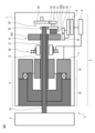
- FIG. 1 is a schematic side view of a position detection system according to a first embodiment of the present disclosure
- FIG. 2 is a front view of the additional reduction gear shown in FIG. 1
- FIG. 2 is a schematic side view of a position detection system according to a second embodiment of the present disclosure
- 4 is a diagram showing a modification of FIG. 3.
- FIG. 1 is a schematic side view of a position detection system according to a first embodiment of the present disclosure.
- the position detection system 5 is built into a machine 3 having a shaft, for example a joint shaft of a robot 3 .
- the case where the position detection system 5 is built into the robot 3 will be described below, but the same applies to the case where the position detection system 5 is built into another machine 3 having a shaft, such as a machine tool.
- the actuator 6 arranged on the link 1 includes a motor 10 connected to each other, for example, a servo motor, and a reduction gear 20 connected to a motor shaft portion 13 of the motor 10.
- Motor 10 includes a rotor 12 that rotates integrally with a motor shaft 13 and a stator 11 that is arranged to surround rotor 12.
- the tip of the output shaft 23 of the speed reducer 20 is connected to the link 2. Therefore, the actuator 6 including the motor 10 and the speed reducer 20 controls the positioning of the link 2 by rotating it relative to the link 1 within a predetermined operating range.
- the reduction ratio of the reduction gear 20 is, for example, 1:50.
- the motor shaft 13 is, for example, a hollow shaft, and a primary encoder 15 is attached to its rear end.
- the primary encoder 15 is, for example, an incremental encoder, and outputs A-phase, B-phase, and Z-phase signals.
- the output signal is detected by the detection unit 16, and the absolute position PA1 within one rotation of the motor shaft 13 and the total number of rotations PB1 are detected by a known method.
- the detected information is stored in a memory 7, for example a volatile memory.
- the output shaft 23 extends toward the motor 10 through the hollow motor shaft 13, and the rear end of the output shaft 23 is connected to the secondary encoder 25 via an additional reduction gear 30, which will be described later.
- the secondary encoder 25 is, for example, an incremental encoder, and outputs A-phase, B-phase, and Z-phase signals.
- the output signal is detected by the detection unit 26, and the absolute position PA2 within one rotation of the output shaft 23 and the total number of rotations PB2 are detected by a known method.
- the detected information is stored in a memory 7, for example a volatile memory.
- the primary encoder 15 and the secondary encoder 25 each include rotating disks 15A and 25A.
- the information stored in the memory 7 is stored for a certain period of time by a battery 8, such as a button battery or a capacitor.
- a battery 8 such as a button battery or a capacitor.
- a common memory 7 and a common battery 8 are provided for the primary encoder 15 and the secondary encoder 25.
- the primary encoder 15 and the secondary encoder 25 may each have separate memories and batteries.
- the information stored in the memory 7 is supplied to a controller 9 that controls the machine 3.
- the controller 9 may be an LSI mounted on the encoders 15 and 25.
- the controller 9 drives and controls the motor 10 based on the supplied information, and performs a positioning operation to position the link 2 at a target position with respect to the link 1.
- a built-in brake 50 provided on the outer surface of the motor shaft 13 is activated in response to an instruction from the controller 9 to brake the motor shaft 13.
- the controller 9 also serves to energize the primary encoder 15 and the secondary encoder 25 during operation of the machine 3 with the links 1, 2.
- FIG. 2 is a front view of the additional reduction gear shown in FIG. 1.
- the additional speed reducer 30 in the first embodiment is a planetary gear device.
- the additional reduction gear 30 can be prepared at relatively low cost.
- a reduction gear mechanism other than the planetary gear device such as a wave gear reduction gear or a cycloid reduction gear, may be used as the additional reduction gear 30.
- the additional reduction gear 30 shown in FIG. 2 includes a sun gear 19 fixed to the rear end of the motor shaft 13, a plurality of, for example, four, planetary gears 32 that engage with the sun gear 19, and a plurality of planetary gears 32. It has a surrounding outer ring 31 and a carrier 35 that rotatably engages with each central axis of a plurality of planetary gears 32. As can be seen from FIG. 1, the shaft extending from the center of the carrier 35 is coaxial with the motor shaft 13 of the motor 10 and the output shaft 23 of the reducer 20, and is connected to the rotating disk 25A of the secondary encoder 25. .
- the additional reducer 30 is arranged between the output shaft 23 of the reducer 20 and the secondary encoder 25.
- An actuator 6 consisting of a motor 10 and a speed reducer 20 is placed in a specific machine 3, for example, a robot 3, which is equipped with a shaft portion 23 capable of rotating at ⁇ 360° or more and ⁇ 720° or less (one rotation or more and two rotations or less). may be done.
- the reduction ratio of the additional reduction gear 30 is such that the rotation disk 25A for the secondary encoder 25 is within one rotation throughout the movable range of the machine 3 equipped with the motor 10 and the reduction gear 20.
- the outer diameter D1 of the sun gear 19 is 16 mm, and the inner diameter D2 of the outer ring 31 is 26 mm.
- the rotating disk 25A of the secondary encoder 25 rotates within one rotation (within ⁇ 360°).
- the outer diameter D1 of the sun gear 19 and the inner diameter of the outer ring 31 may be set so as to satisfy the following conditions (1) and (2).
- Secondary encoder 25 can continue to be used. That is, in the embodiment of the present disclosure, even when performing a rotation operation of ⁇ 360° or more and ⁇ 720° or less (one rotation or more and two rotations or less), the rotation operation continues over the entire movable range of the output shaft 23 without a battery. It becomes possible to provide a position detection system 5 that can be used as It goes without saying that the primary encoder 15 can also be used continuously throughout the entire movable range of the output shaft 23.
- the position detection system 5 is preferably incorporated into the joint shaft of the robot 3.
- the joint axes of the robot 3 often perform rotational movements of ⁇ 360° or more and ⁇ 720° or less (one rotation or more and two rotations or less). Therefore, even in such a case, it is particularly advantageous because the position detection system 5 can be used continuously without a battery in the above rotational movement range of the joint axis.
- FIG. 3 is a schematic side view of a position detection system based on a second embodiment of the present disclosure.
- the additional speed reducer 30' in the second embodiment is a combination of two spur gears and a double gear.
- the additional reduction gear 30' includes a spur gear 39 fixed to the rear end of the motor shaft 13, a two-stage gear 35 including a large-diameter gear 31 and a small-diameter gear 32, and a spur gear 29. include.
- the spur gear 39 and the large-diameter gear 31 of the two-stage gear 35 are engaged, and the small-diameter gear 32 of the two-stage gear 35 and the spur gear 39 are engaged.
- the secondary encoder 25 is arranged on the end surface of the large diameter gear 31. Therefore, the secondary encoder 25 shown in FIG. 3 detects the speed of the output shaft 23 reduced by the first reduction ratio.
- FIG. 4 is a diagram showing a modification of FIG. 3.
- the same additional reducer 30' as described above is arranged.
- the secondary encoder 25 is arranged on the end face of the spur gear 29. Therefore, the secondary encoder 25 shown in FIG. 4 detects the speed of the output shaft 23 reduced by the first reduction ratio and the second reduction ratio.
- the speed of the output shaft 23 is reduced by the first reduction ratio between the spur gear 39 and the large diameter gear 31 of the two stage gear 35, and the speed of the output shaft 23 is reduced by the first reduction ratio between the spur gear 39 and the large diameter gear 31 of the two stage gear 35.
- the speed of the output shaft 23 is reduced by the second reduction ratio.
- the reduction ratio of the additional reduction gear 30' (the product obtained by multiplying the first reduction ratio and the second reduction ratio) is the reduction ratio of the machine 3 equipped with the motor 10 and the reduction gear 20.
- the rotating disk 25A for the secondary encoder 25 is set to rotate within one rotation throughout the movable range. It will be seen that this provides the same effect as described above.
- a primary encoder detects the position of a motor shaft of a motor
- a secondary encoder detects a position of an output shaft of a reduction gear coupled to the motor, and an output of the reduction gear.
- an additional reducer disposed between the shaft and the secondary encoder, the reduction ratio of the additional reducer being equal to or lower than that of the secondary encoder over the entire movable range of the machine provided with the motor and the reducer;
- a position detection system is provided in which the rotating disk is configured to be within one revolution.
- the additional reduction gear is a planetary gear device, a strain wave gear reduction gear, a cycloid reduction gear, or a combination of a spur gear and a two-stage gear.
- the position detection system is mounted on the robot.
- An additional reduction gear is provided between the output shaft of the reduction gear and the secondary encoder, and the reduction ratio of the additional reduction gear is within the entire movable range of the machine equipped with the motor and the reduction gear.
- an actuator is provided in which the rotating disk for the secondary encoder is configured to rotate within one rotation.
- the additional reduction gear is a planetary gear device, a wave gear reduction gear, a cycloid reduction gear, or a combination of a spur gear and a two-stage gear.
- the actuator is mounted on a robot.
Landscapes
- Engineering & Computer Science (AREA)
- Power Engineering (AREA)
- Microelectronics & Electronic Packaging (AREA)
- Physics & Mathematics (AREA)
- General Physics & Mathematics (AREA)
- Manipulator (AREA)
- Control Of Electric Motors In General (AREA)
- Retarders (AREA)
Priority Applications (6)
| Application Number | Priority Date | Filing Date | Title |
|---|---|---|---|
| US18/877,103 US20250379495A1 (en) | 2022-07-08 | 2022-07-08 | Position detection system and actuator |
| JP2024531898A JPWO2024009515A1 (https=) | 2022-07-08 | 2022-07-08 | |
| CN202280097593.0A CN119487361A (zh) | 2022-07-08 | 2022-07-08 | 位置检测系统以及致动器 |
| PCT/JP2022/027153 WO2024009515A1 (ja) | 2022-07-08 | 2022-07-08 | 位置検出システムおよびアクチュエータ |
| DE112022007182.6T DE112022007182T5 (de) | 2022-07-08 | 2022-07-08 | Positionserfassungssystem und aktuator |
| TW112121344A TW202417815A (zh) | 2022-07-08 | 2023-06-08 | 位置檢測系統及致動器 |
Applications Claiming Priority (1)
| Application Number | Priority Date | Filing Date | Title |
|---|---|---|---|
| PCT/JP2022/027153 WO2024009515A1 (ja) | 2022-07-08 | 2022-07-08 | 位置検出システムおよびアクチュエータ |
Publications (1)
| Publication Number | Publication Date |
|---|---|
| WO2024009515A1 true WO2024009515A1 (ja) | 2024-01-11 |
Family
ID=89452913
Family Applications (1)
| Application Number | Title | Priority Date | Filing Date |
|---|---|---|---|
| PCT/JP2022/027153 Ceased WO2024009515A1 (ja) | 2022-07-08 | 2022-07-08 | 位置検出システムおよびアクチュエータ |
Country Status (6)
| Country | Link |
|---|---|
| US (1) | US20250379495A1 (https=) |
| JP (1) | JPWO2024009515A1 (https=) |
| CN (1) | CN119487361A (https=) |
| DE (1) | DE112022007182T5 (https=) |
| TW (1) | TW202417815A (https=) |
| WO (1) | WO2024009515A1 (https=) |
Citations (7)
| Publication number | Priority date | Publication date | Assignee | Title |
|---|---|---|---|---|
| JP2002116057A (ja) * | 2000-10-06 | 2002-04-19 | Yaskawa Electric Corp | 多回転式絶対値エンコーダ装置 |
| WO2007046182A1 (ja) * | 2005-10-18 | 2007-04-26 | Harmonic Drive Systems Inc. | ギヤ付きモータの多回転絶対値エンコーダ |
| WO2010023896A1 (ja) * | 2008-08-26 | 2010-03-04 | 株式会社ニコン | エンコーダシステム、信号処理方法、及び送信信号生成出力装置 |
| JP2015206747A (ja) * | 2014-04-23 | 2015-11-19 | 株式会社ニコン | エンコーダ装置、駆動装置、ステージ装置、及びロボット装置 |
| JP2016124094A (ja) * | 2015-01-08 | 2016-07-11 | ファナック株式会社 | 複数の回転角検出器により回転角を更新するロボット制御装置 |
| JP2018100859A (ja) * | 2016-12-19 | 2018-06-28 | 株式会社ハーモニック・ドライブ・システムズ | ギヤ付きモータのアブソリュートエンコーダ |
| JP2020099148A (ja) * | 2018-12-19 | 2020-06-25 | Thk株式会社 | アクチュエータ |
Family Cites Families (2)
| Publication number | Priority date | Publication date | Assignee | Title |
|---|---|---|---|---|
| JPH11132792A (ja) * | 1997-10-31 | 1999-05-21 | Yaskawa Electric Corp | 多回転型アブソリュートエンコーダ |
| US11181170B2 (en) * | 2016-06-06 | 2021-11-23 | National University Corporation Yokohama National University | Planetary gear device and planetary gear device design program |
-
2022
- 2022-07-08 CN CN202280097593.0A patent/CN119487361A/zh active Pending
- 2022-07-08 US US18/877,103 patent/US20250379495A1/en active Pending
- 2022-07-08 WO PCT/JP2022/027153 patent/WO2024009515A1/ja not_active Ceased
- 2022-07-08 JP JP2024531898A patent/JPWO2024009515A1/ja active Pending
- 2022-07-08 DE DE112022007182.6T patent/DE112022007182T5/de not_active Withdrawn
-
2023
- 2023-06-08 TW TW112121344A patent/TW202417815A/zh unknown
Patent Citations (7)
| Publication number | Priority date | Publication date | Assignee | Title |
|---|---|---|---|---|
| JP2002116057A (ja) * | 2000-10-06 | 2002-04-19 | Yaskawa Electric Corp | 多回転式絶対値エンコーダ装置 |
| WO2007046182A1 (ja) * | 2005-10-18 | 2007-04-26 | Harmonic Drive Systems Inc. | ギヤ付きモータの多回転絶対値エンコーダ |
| WO2010023896A1 (ja) * | 2008-08-26 | 2010-03-04 | 株式会社ニコン | エンコーダシステム、信号処理方法、及び送信信号生成出力装置 |
| JP2015206747A (ja) * | 2014-04-23 | 2015-11-19 | 株式会社ニコン | エンコーダ装置、駆動装置、ステージ装置、及びロボット装置 |
| JP2016124094A (ja) * | 2015-01-08 | 2016-07-11 | ファナック株式会社 | 複数の回転角検出器により回転角を更新するロボット制御装置 |
| JP2018100859A (ja) * | 2016-12-19 | 2018-06-28 | 株式会社ハーモニック・ドライブ・システムズ | ギヤ付きモータのアブソリュートエンコーダ |
| JP2020099148A (ja) * | 2018-12-19 | 2020-06-25 | Thk株式会社 | アクチュエータ |
Also Published As
| Publication number | Publication date |
|---|---|
| CN119487361A (zh) | 2025-02-18 |
| TW202417815A (zh) | 2024-05-01 |
| JPWO2024009515A1 (https=) | 2024-01-11 |
| US20250379495A1 (en) | 2025-12-11 |
| DE112022007182T5 (de) | 2025-04-30 |
Similar Documents
| Publication | Publication Date | Title |
|---|---|---|
| JP5400473B2 (ja) | ロボット装置 | |
| JP2021531442A (ja) | 完全閉ループ制御を実現できる遊星減速モータ及び多関節ロボット | |
| CN100430190C (zh) | 工业机器人的减速装置 | |
| US7377875B2 (en) | Planetary gear apparatus and steering apparatus with planetary gear apparatus | |
| US20120079904A1 (en) | Joint device and control method thereof | |
| EP1894683A1 (en) | Industrial robot | |
| WO2013175553A1 (ja) | ロボット | |
| CN104024694A (zh) | 连杆动作装置的原点位置初始设定方法和连杆动作装置 | |
| US11078988B2 (en) | Transmission assembly | |
| JP3450074B2 (ja) | 遊星差動型減速機の制御装置 | |
| JP6808474B2 (ja) | ギヤ付きモータのアブソリュートエンコーダ | |
| US20170001304A1 (en) | Actuator | |
| CN106737642A (zh) | 基于双伺服电机的减速驱动装置、驱动系统及控制方法 | |
| JP5911697B2 (ja) | パラレルリンク機構、等速自在継手、およびリンク作動装置 | |
| KR101171810B1 (ko) | 외전형 모터를 가진 머니퓰레이터 | |
| CN206406056U (zh) | 基于双伺服电机的减速驱动装置及驱动系统 | |
| WO2024009515A1 (ja) | 位置検出システムおよびアクチュエータ | |
| US20220388154A1 (en) | Improved delta robot | |
| JP2014238117A (ja) | 減速機内蔵アクチュエータ及びこれを備える多関節ロボット | |
| JP2026511193A (ja) | 出力モードを調整可能な中空のロボット関節モジュール | |
| JP2016003754A (ja) | 減速機、ロボットおよびロボットシステム | |
| JP2004299000A (ja) | 産業用ロボットの関節駆動装置 | |
| JP2591028B2 (ja) | 油圧ロータリアクチュエータ | |
| WO2024009516A1 (ja) | 位置検出システム、アクチュエータおよび位置検出方法 | |
| JP7727748B2 (ja) | モータ制御装置 |
Legal Events
| Date | Code | Title | Description |
|---|---|---|---|
| 121 | Ep: the epo has been informed by wipo that ep was designated in this application |
Ref document number: 22950309 Country of ref document: EP Kind code of ref document: A1 |
|
| ENP | Entry into the national phase |
Ref document number: 2024531898 Country of ref document: JP Kind code of ref document: A |
|
| WWE | Wipo information: entry into national phase |
Ref document number: 112022007182 Country of ref document: DE Ref document number: 18877103 Country of ref document: US |
|
| WWE | Wipo information: entry into national phase |
Ref document number: 202280097593.0 Country of ref document: CN |
|
| WWP | Wipo information: published in national office |
Ref document number: 202280097593.0 Country of ref document: CN |
|
| WWP | Wipo information: published in national office |
Ref document number: 112022007182 Country of ref document: DE |
|
| 122 | Ep: pct application non-entry in european phase |
Ref document number: 22950309 Country of ref document: EP Kind code of ref document: A1 |
|
| WWP | Wipo information: published in national office |
Ref document number: 18877103 Country of ref document: US |