WO2024009515A1 - Position detection system and actuator - Google Patents
Position detection system and actuator Download PDFInfo
- Publication number
- WO2024009515A1 WO2024009515A1 PCT/JP2022/027153 JP2022027153W WO2024009515A1 WO 2024009515 A1 WO2024009515 A1 WO 2024009515A1 JP 2022027153 W JP2022027153 W JP 2022027153W WO 2024009515 A1 WO2024009515 A1 WO 2024009515A1
- Authority
- WO
- WIPO (PCT)
- Prior art keywords
- motor
- gear
- reduction gear
- encoder
- additional
- Prior art date
Links
- 238000001514 detection method Methods 0.000 title claims abstract description 23
- 230000009467 reduction Effects 0.000 claims abstract description 64
- 239000003638 chemical reducing agent Substances 0.000 claims abstract description 39
- 230000015654 memory Effects 0.000 description 10
- 238000000034 method Methods 0.000 description 3
- 238000010586 diagram Methods 0.000 description 2
- 230000004048 modification Effects 0.000 description 2
- 238000012986 modification Methods 0.000 description 2
- 238000007792 addition Methods 0.000 description 1
- 239000003990 capacitor Substances 0.000 description 1
- 238000012217 deletion Methods 0.000 description 1
- 230000037430 deletion Effects 0.000 description 1
- 230000000694 effects Effects 0.000 description 1
- 230000007246 mechanism Effects 0.000 description 1
- 230000008569 process Effects 0.000 description 1
- 230000004044 response Effects 0.000 description 1
- 238000006467 substitution reaction Methods 0.000 description 1
Images


Classifications
-
- G—PHYSICS
- G01—MEASURING; TESTING
- G01D—MEASURING NOT SPECIALLY ADAPTED FOR A SPECIFIC VARIABLE; ARRANGEMENTS FOR MEASURING TWO OR MORE VARIABLES NOT COVERED IN A SINGLE OTHER SUBCLASS; TARIFF METERING APPARATUS; MEASURING OR TESTING NOT OTHERWISE PROVIDED FOR
- G01D5/00—Mechanical means for transferring the output of a sensing member; Means for converting the output of a sensing member to another variable where the form or nature of the sensing member does not constrain the means for converting; Transducers not specially adapted for a specific variable
- G01D5/02—Mechanical means for transferring the output of a sensing member; Means for converting the output of a sensing member to another variable where the form or nature of the sensing member does not constrain the means for converting; Transducers not specially adapted for a specific variable using mechanical means
- G01D5/04—Mechanical means for transferring the output of a sensing member; Means for converting the output of a sensing member to another variable where the form or nature of the sensing member does not constrain the means for converting; Transducers not specially adapted for a specific variable using mechanical means using levers; using cams; using gearing
Definitions
- the present disclosure relates to a position detection system and an actuator.
- the actuator includes a servo motor and a speed reducer that are connected to each other.
- a primary encoder is connected to the motor shaft of the servo motor, and detects the absolute position within one rotation of the motor shaft and the total number of rotations of the motor shaft.
- a secondary encoder is connected to the output shaft of the reducer, and detects the absolute position within one rotation of the output shaft and the total number of rotations of the output shaft (for example, Japanese Patent Laid-Open No. 2007-113932 (see official bulletin). Information detected by each encoder is stored in memory.
- each encoder can be used continuously without using an additional battery.
- the above-mentioned actuator may be incorporated into a specific machine, such as a robot, which has a shaft portion that can perform rotational motion of ⁇ 360° or more and ⁇ 720° or less (one rotation or more and two rotations or less). In order to continue using each encoder when the shaft rotates at least one rotation and at most two rotations, it is necessary to prepare an additional battery.
- a primary encoder that detects the position of a motor shaft of a motor
- a secondary encoder that detects a position of an output shaft of a reduction gear coupled to the motor
- an output shaft of the reduction gear coupled to the motor an additional reducer disposed between the secondary encoder and the additional reducer, and the reduction ratio of the additional reducer is set to a rotating disk for the secondary encoder throughout the movable range of the machine provided with the motor and the reducer.
- a position sensing system is provided that is configured such that the position is within one rotation.
- a motor a reduction gear coupled to the motor, a primary encoder that detects a position of a motor shaft of the motor, and a secondary encoder that detects a position of an output shaft of the reduction gear.
- an additional reducer disposed between the output shaft of the reducer and the secondary encoder, and the reduction ratio of the additional reducer is within the movable range of the machine equipped with the motor and the reducer.
- An actuator is provided that is configured such that the rotating disk for the secondary encoder is within one revolution over its entire range.
- FIG. 1 is a schematic side view of a position detection system according to a first embodiment of the present disclosure
- FIG. 2 is a front view of the additional reduction gear shown in FIG. 1
- FIG. 2 is a schematic side view of a position detection system according to a second embodiment of the present disclosure
- 4 is a diagram showing a modification of FIG. 3.
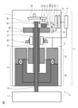
- FIG. 1 is a schematic side view of a position detection system according to a first embodiment of the present disclosure.
- the position detection system 5 is built into a machine 3 having a shaft, for example a joint shaft of a robot 3 .
- the case where the position detection system 5 is built into the robot 3 will be described below, but the same applies to the case where the position detection system 5 is built into another machine 3 having a shaft, such as a machine tool.
- the actuator 6 arranged on the link 1 includes a motor 10 connected to each other, for example, a servo motor, and a reduction gear 20 connected to a motor shaft portion 13 of the motor 10.
- Motor 10 includes a rotor 12 that rotates integrally with a motor shaft 13 and a stator 11 that is arranged to surround rotor 12.
- the tip of the output shaft 23 of the speed reducer 20 is connected to the link 2. Therefore, the actuator 6 including the motor 10 and the speed reducer 20 controls the positioning of the link 2 by rotating it relative to the link 1 within a predetermined operating range.
- the reduction ratio of the reduction gear 20 is, for example, 1:50.
- the motor shaft 13 is, for example, a hollow shaft, and a primary encoder 15 is attached to its rear end.
- the primary encoder 15 is, for example, an incremental encoder, and outputs A-phase, B-phase, and Z-phase signals.
- the output signal is detected by the detection unit 16, and the absolute position PA1 within one rotation of the motor shaft 13 and the total number of rotations PB1 are detected by a known method.
- the detected information is stored in a memory 7, for example a volatile memory.
- the output shaft 23 extends toward the motor 10 through the hollow motor shaft 13, and the rear end of the output shaft 23 is connected to the secondary encoder 25 via an additional reduction gear 30, which will be described later.
- the secondary encoder 25 is, for example, an incremental encoder, and outputs A-phase, B-phase, and Z-phase signals.
- the output signal is detected by the detection unit 26, and the absolute position PA2 within one rotation of the output shaft 23 and the total number of rotations PB2 are detected by a known method.
- the detected information is stored in a memory 7, for example a volatile memory.
- the primary encoder 15 and the secondary encoder 25 each include rotating disks 15A and 25A.
- the information stored in the memory 7 is stored for a certain period of time by a battery 8, such as a button battery or a capacitor.
- a battery 8 such as a button battery or a capacitor.
- a common memory 7 and a common battery 8 are provided for the primary encoder 15 and the secondary encoder 25.
- the primary encoder 15 and the secondary encoder 25 may each have separate memories and batteries.
- the information stored in the memory 7 is supplied to a controller 9 that controls the machine 3.
- the controller 9 may be an LSI mounted on the encoders 15 and 25.
- the controller 9 drives and controls the motor 10 based on the supplied information, and performs a positioning operation to position the link 2 at a target position with respect to the link 1.
- a built-in brake 50 provided on the outer surface of the motor shaft 13 is activated in response to an instruction from the controller 9 to brake the motor shaft 13.
- the controller 9 also serves to energize the primary encoder 15 and the secondary encoder 25 during operation of the machine 3 with the links 1, 2.
- FIG. 2 is a front view of the additional reduction gear shown in FIG. 1.
- the additional speed reducer 30 in the first embodiment is a planetary gear device.
- the additional reduction gear 30 can be prepared at relatively low cost.
- a reduction gear mechanism other than the planetary gear device such as a wave gear reduction gear or a cycloid reduction gear, may be used as the additional reduction gear 30.
- the additional reduction gear 30 shown in FIG. 2 includes a sun gear 19 fixed to the rear end of the motor shaft 13, a plurality of, for example, four, planetary gears 32 that engage with the sun gear 19, and a plurality of planetary gears 32. It has a surrounding outer ring 31 and a carrier 35 that rotatably engages with each central axis of a plurality of planetary gears 32. As can be seen from FIG. 1, the shaft extending from the center of the carrier 35 is coaxial with the motor shaft 13 of the motor 10 and the output shaft 23 of the reducer 20, and is connected to the rotating disk 25A of the secondary encoder 25. .
- the additional reducer 30 is arranged between the output shaft 23 of the reducer 20 and the secondary encoder 25.
- An actuator 6 consisting of a motor 10 and a speed reducer 20 is placed in a specific machine 3, for example, a robot 3, which is equipped with a shaft portion 23 capable of rotating at ⁇ 360° or more and ⁇ 720° or less (one rotation or more and two rotations or less). may be done.
- the reduction ratio of the additional reduction gear 30 is such that the rotation disk 25A for the secondary encoder 25 is within one rotation throughout the movable range of the machine 3 equipped with the motor 10 and the reduction gear 20.
- the outer diameter D1 of the sun gear 19 is 16 mm, and the inner diameter D2 of the outer ring 31 is 26 mm.
- the rotating disk 25A of the secondary encoder 25 rotates within one rotation (within ⁇ 360°).
- the outer diameter D1 of the sun gear 19 and the inner diameter of the outer ring 31 may be set so as to satisfy the following conditions (1) and (2).
- Secondary encoder 25 can continue to be used. That is, in the embodiment of the present disclosure, even when performing a rotation operation of ⁇ 360° or more and ⁇ 720° or less (one rotation or more and two rotations or less), the rotation operation continues over the entire movable range of the output shaft 23 without a battery. It becomes possible to provide a position detection system 5 that can be used as It goes without saying that the primary encoder 15 can also be used continuously throughout the entire movable range of the output shaft 23.
- the position detection system 5 is preferably incorporated into the joint shaft of the robot 3.
- the joint axes of the robot 3 often perform rotational movements of ⁇ 360° or more and ⁇ 720° or less (one rotation or more and two rotations or less). Therefore, even in such a case, it is particularly advantageous because the position detection system 5 can be used continuously without a battery in the above rotational movement range of the joint axis.
- FIG. 3 is a schematic side view of a position detection system based on a second embodiment of the present disclosure.
- the additional speed reducer 30' in the second embodiment is a combination of two spur gears and a double gear.
- the additional reduction gear 30' includes a spur gear 39 fixed to the rear end of the motor shaft 13, a two-stage gear 35 including a large-diameter gear 31 and a small-diameter gear 32, and a spur gear 29. include.
- the spur gear 39 and the large-diameter gear 31 of the two-stage gear 35 are engaged, and the small-diameter gear 32 of the two-stage gear 35 and the spur gear 39 are engaged.
- the secondary encoder 25 is arranged on the end surface of the large diameter gear 31. Therefore, the secondary encoder 25 shown in FIG. 3 detects the speed of the output shaft 23 reduced by the first reduction ratio.
- FIG. 4 is a diagram showing a modification of FIG. 3.
- the same additional reducer 30' as described above is arranged.
- the secondary encoder 25 is arranged on the end face of the spur gear 29. Therefore, the secondary encoder 25 shown in FIG. 4 detects the speed of the output shaft 23 reduced by the first reduction ratio and the second reduction ratio.
- the speed of the output shaft 23 is reduced by the first reduction ratio between the spur gear 39 and the large diameter gear 31 of the two stage gear 35, and the speed of the output shaft 23 is reduced by the first reduction ratio between the spur gear 39 and the large diameter gear 31 of the two stage gear 35.
- the speed of the output shaft 23 is reduced by the second reduction ratio.
- the reduction ratio of the additional reduction gear 30' (the product obtained by multiplying the first reduction ratio and the second reduction ratio) is the reduction ratio of the machine 3 equipped with the motor 10 and the reduction gear 20.
- the rotating disk 25A for the secondary encoder 25 is set to rotate within one rotation throughout the movable range. It will be seen that this provides the same effect as described above.
- a primary encoder detects the position of a motor shaft of a motor
- a secondary encoder detects a position of an output shaft of a reduction gear coupled to the motor, and an output of the reduction gear.
- an additional reducer disposed between the shaft and the secondary encoder, the reduction ratio of the additional reducer being equal to or lower than that of the secondary encoder over the entire movable range of the machine provided with the motor and the reducer;
- a position detection system is provided in which the rotating disk is configured to be within one revolution.
- the additional reduction gear is a planetary gear device, a strain wave gear reduction gear, a cycloid reduction gear, or a combination of a spur gear and a two-stage gear.
- the position detection system is mounted on the robot.
- An additional reduction gear is provided between the output shaft of the reduction gear and the secondary encoder, and the reduction ratio of the additional reduction gear is within the entire movable range of the machine equipped with the motor and the reduction gear.
- an actuator is provided in which the rotating disk for the secondary encoder is configured to rotate within one rotation.
- the additional reduction gear is a planetary gear device, a wave gear reduction gear, a cycloid reduction gear, or a combination of a spur gear and a two-stage gear.
- the actuator is mounted on a robot.
Abstract
This position detection system (1) includes a primary encoder (15) that detects the position of a motor shaft (13) of a motor (10), a secondary encoder (25) that detects the position of an output shaft (23) of a reducer (20), and an additional reducer (30, 30') that is disposed between the output shaft (23) and the secondary encoder (25). The reduction ratio of the additional reducer is set such that a rotating disc (25A) for the secondary encoder is within a single rotation of the entirety of the movable range of a machine provided with the motor and the reducer.
Description
本開示は、位置検出システムおよびアクチュエータに関する。
The present disclosure relates to a position detection system and an actuator.
アクチュエータは、互いに連結されたサーボモータおよび減速機を含んでいる。サーボモータのモータ軸には、プライマリエンコーダが連結されていて、モータ軸の一回転内のアブソリュート位置と、モータ軸の総回転回数とを検出している。同様に、減速機の出力軸には、セカンダリエンコーダが連結されていて、出力軸の一回転内のアブソリュート位置と、出力軸の総回転回数とを検出している(例えば特開2007-113932号公報参照)。各エンコーダにより検出された情報はメモリに保存される。
The actuator includes a servo motor and a speed reducer that are connected to each other. A primary encoder is connected to the motor shaft of the servo motor, and detects the absolute position within one rotation of the motor shaft and the total number of rotations of the motor shaft. Similarly, a secondary encoder is connected to the output shaft of the reducer, and detects the absolute position within one rotation of the output shaft and the total number of rotations of the output shaft (for example, Japanese Patent Laid-Open No. 2007-113932 (see official bulletin). Information detected by each encoder is stored in memory.
特定の事態、例えばサーボモータが停止して、減速機の出力軸が惰性で回転する事態において、減速機の出力軸が一回転以内で回転する限りにおいては、セカンダリエンコーダのアブソリュート位置の情報に基づいて、プライマリエンコーダの総回転回数の情報を得ることができる。この場合には、追加のバッテリを使用することなしに、各エンコーダを継続して使用できる。
In certain situations, for example, when the servo motor is stopped and the output shaft of the reducer rotates due to inertia, as long as the output shaft of the reducer rotates within one rotation, the information of the absolute position of the secondary encoder is used. Thus, information on the total number of rotations of the primary encoder can be obtained. In this case, each encoder can be used continuously without using an additional battery.
前述したアクチュエータは、±360°以上±720°以下(1回転以上2回転以下)の回転動作をしうる軸部を備えた特定の機械、例えばロボットに組み込まれる場合がある。軸部が1回転以上2回転以下で回転する場合に、各エンコーダを継続して使用するためには、追加のバッテリを準備する必要がある。
The above-mentioned actuator may be incorporated into a specific machine, such as a robot, which has a shaft portion that can perform rotational motion of ±360° or more and ±720° or less (one rotation or more and two rotations or less). In order to continue using each encoder when the shaft rotates at least one rotation and at most two rotations, it is necessary to prepare an additional battery.
それゆえ、追加のバッテリを必要とすることなしに、軸部の可動範囲全体において継続して使用することのできるエンコーダが望まれている。
Therefore, it is desirable to have an encoder that can be used continuously throughout the range of motion of the shaft without the need for additional batteries.
本開示の1番目の態様によれば、モータのモータ軸の位置を検出するプライマリエンコーダと、モータに結合される減速機の出力軸の位置を検出するセカンダリエンコーダと、前記減速機の出力軸と前記セカンダリエンコーダとの間に配置された追加減速機とを具備し、該追加減速機の減速比は、前記モータおよび前記減速機が備えられた機械の可動範囲の全域においてセカンダリエンコーダ用の回転ディスクが一回転以内であるように設定される、位置検出システムが提供される。
さらに、他の態様によれば、モータと、該モータに結合される減速機と、前記モータのモータ軸の位置を検出するプライマリエンコーダと、前記減速機の出力軸の位置を検出するセカンダリエンコーダと、前記減速機の出力軸と前記セカンダリエンコーダとの間に配置された追加減速機とを具備し、該追加減速機の減速比は、前記モータおよび前記減速機が備えられた機械の可動範囲の全域においてセカンダリエンコーダ用の回転ディスクが一回転以内であるように設定される、アクチュエータが提供される。 According to a first aspect of the present disclosure, there is provided a primary encoder that detects the position of a motor shaft of a motor, a secondary encoder that detects a position of an output shaft of a reduction gear coupled to the motor, and an output shaft of the reduction gear coupled to the motor. an additional reducer disposed between the secondary encoder and the additional reducer, and the reduction ratio of the additional reducer is set to a rotating disk for the secondary encoder throughout the movable range of the machine provided with the motor and the reducer. A position sensing system is provided that is configured such that the position is within one rotation.
Furthermore, according to another aspect, a motor, a reduction gear coupled to the motor, a primary encoder that detects a position of a motor shaft of the motor, and a secondary encoder that detects a position of an output shaft of the reduction gear. , an additional reducer disposed between the output shaft of the reducer and the secondary encoder, and the reduction ratio of the additional reducer is within the movable range of the machine equipped with the motor and the reducer. An actuator is provided that is configured such that the rotating disk for the secondary encoder is within one revolution over its entire range.
本開示の目的、特徴及び利点は、添付図面に関連した以下の実施形態の説明により一層明らかになろう。
Objects, features, and advantages of the present disclosure will become more apparent from the following description of embodiments in conjunction with the accompanying drawings.
以下、添付図面を参照して本開示の実施の形態を説明する。全図面に渡り、対応する構成要素には共通の参照符号を付す。
図1は本開示の第一の実施形態に基づく位置検出システムの略側面図である。位置検出システム5は、軸部を有する機械3、例えばロボット3の関節軸に組み込まれている。以下、位置検出システム5がロボット3に組み込まれている場合について説明するが、位置検出システム5が軸部を有する他の機械3、例えば工作機械に組み込まれている場合についても同様である。 Embodiments of the present disclosure will be described below with reference to the accompanying drawings. Corresponding components are given common reference numerals throughout the drawings.
FIG. 1 is a schematic side view of a position detection system according to a first embodiment of the present disclosure. Theposition detection system 5 is built into a machine 3 having a shaft, for example a joint shaft of a robot 3 . The case where the position detection system 5 is built into the robot 3 will be described below, but the same applies to the case where the position detection system 5 is built into another machine 3 having a shaft, such as a machine tool.
図1は本開示の第一の実施形態に基づく位置検出システムの略側面図である。位置検出システム5は、軸部を有する機械3、例えばロボット3の関節軸に組み込まれている。以下、位置検出システム5がロボット3に組み込まれている場合について説明するが、位置検出システム5が軸部を有する他の機械3、例えば工作機械に組み込まれている場合についても同様である。 Embodiments of the present disclosure will be described below with reference to the accompanying drawings. Corresponding components are given common reference numerals throughout the drawings.
FIG. 1 is a schematic side view of a position detection system according to a first embodiment of the present disclosure. The
図1においては、リンク1に配置されたアクチュエータ6は、互いに連結されたモータ10、例えばサーボモータおよび、モータ10のモータ軸部13に連結された減速機20を含んでいる。モータ10は、モータ軸13と一体的に回転するロータ12と、ロータ12を取り囲むように配置されるステータ11とを含む。減速機20の出力軸23の先端は、リンク2に連結されている。従って、モータ10および減速機20からなるアクチュエータ6は、リンク2をリンク1に対して所定の動作範囲内で相対的に回転させて位置決め制御する。なお、減速機20の減速比は、例えば1:50である。
In FIG. 1, the actuator 6 arranged on the link 1 includes a motor 10 connected to each other, for example, a servo motor, and a reduction gear 20 connected to a motor shaft portion 13 of the motor 10. Motor 10 includes a rotor 12 that rotates integrally with a motor shaft 13 and a stator 11 that is arranged to surround rotor 12. The tip of the output shaft 23 of the speed reducer 20 is connected to the link 2. Therefore, the actuator 6 including the motor 10 and the speed reducer 20 controls the positioning of the link 2 by rotating it relative to the link 1 within a predetermined operating range. Note that the reduction ratio of the reduction gear 20 is, for example, 1:50.
モータ軸13は例えば中空軸であり、その後端部には、プライマリエンコーダ15が取付けられている。プライマリエンコーダ15は、例えばインクリメンタルエンコーダであり、A相、B相およびZ相信号を出力する。出力された信号は検出部16により検出され、公知の手法で、モータ軸13の一回転内のアブソリュート位置PA1および総回転回数PB1を検出する。検出された情報はメモリ7、例えば揮発性メモリに保存される。
The motor shaft 13 is, for example, a hollow shaft, and a primary encoder 15 is attached to its rear end. The primary encoder 15 is, for example, an incremental encoder, and outputs A-phase, B-phase, and Z-phase signals. The output signal is detected by the detection unit 16, and the absolute position PA1 within one rotation of the motor shaft 13 and the total number of rotations PB1 are detected by a known method. The detected information is stored in a memory 7, for example a volatile memory.
出力軸23は中空のモータ軸13を通ってモータ10側に延びており、出力軸23の後端部は、後述する追加減速機30を介してセカンダリエンコーダ25に連結されている。セカンダリエンコーダ25は、例えばインクリメンタルエンコーダであり、A相、B相およびZ相信号を出力する。出力された信号は検出部26により検出され、公知の手法で、出力軸23の一回転内のアブソリュート位置PA2および総回転回数PB2を検出する。検出された情報はメモリ7、例えば揮発性メモリに保存される。なお、公知であるように、プライマリエンコーダ15およびセカンダリエンコーダ25はそれぞれ回転ディスク15A、25Aを備えている。
The output shaft 23 extends toward the motor 10 through the hollow motor shaft 13, and the rear end of the output shaft 23 is connected to the secondary encoder 25 via an additional reduction gear 30, which will be described later. The secondary encoder 25 is, for example, an incremental encoder, and outputs A-phase, B-phase, and Z-phase signals. The output signal is detected by the detection unit 26, and the absolute position PA2 within one rotation of the output shaft 23 and the total number of rotations PB2 are detected by a known method. The detected information is stored in a memory 7, for example a volatile memory. Note that, as is well known, the primary encoder 15 and the secondary encoder 25 each include rotating disks 15A and 25A.
メモリ7に保存された情報はバッテリ8、例えばボタン電池またはキャパシタにより一定期間保存されるようになっている。図1では、プライマリエンコーダ15およびセカンダリエンコーダ25について共通のメモリ7および共通のバッテリ8が備えられている。しかしながら、プライマリエンコーダ15およびセカンダリエンコーダ25がそれぞれ別個のメモリおよびバッテリを有する構成であってもよい。
The information stored in the memory 7 is stored for a certain period of time by a battery 8, such as a button battery or a capacitor. In FIG. 1, a common memory 7 and a common battery 8 are provided for the primary encoder 15 and the secondary encoder 25. However, the primary encoder 15 and the secondary encoder 25 may each have separate memories and batteries.
メモリ7に保存された情報は、機械3を制御するコントローラ9に供給される。コントローラ9はエンコーダ15、25に搭載されたLSIであってもよい。コントローラ9は、供給された情報に基づいて、モータ10を駆動制御し、リンク2をリンク1に対して目標位置に位置決めする位置決め動作を行う。さらに、モータ軸13の外面側に備えられた内蔵ブレーキ50は、コントローラ9の指示に応じて起動し、モータ軸13を制動する。さらに、コントローラ9は、リンク1、2を備えた機械3の動作時には、プライマリエンコーダ15およびセカンダリエンコーダ25に通電する役目も果たしている。
The information stored in the memory 7 is supplied to a controller 9 that controls the machine 3. The controller 9 may be an LSI mounted on the encoders 15 and 25. The controller 9 drives and controls the motor 10 based on the supplied information, and performs a positioning operation to position the link 2 at a target position with respect to the link 1. Further, a built-in brake 50 provided on the outer surface of the motor shaft 13 is activated in response to an instruction from the controller 9 to brake the motor shaft 13. Furthermore, the controller 9 also serves to energize the primary encoder 15 and the secondary encoder 25 during operation of the machine 3 with the links 1, 2.
図2は図1に示される追加減速機の正面図である。第一の実施形態における追加減速機30は、遊星歯車装置である。この場合には、追加減速機30を比較的安価で準備することができる。ただし、遊星歯車装置以外の他の減速機構、例えば波動歯車減速機、サイクロイド減速機を追加減速機30として使用してもよい。
FIG. 2 is a front view of the additional reduction gear shown in FIG. 1. The additional speed reducer 30 in the first embodiment is a planetary gear device. In this case, the additional reduction gear 30 can be prepared at relatively low cost. However, a reduction gear mechanism other than the planetary gear device, such as a wave gear reduction gear or a cycloid reduction gear, may be used as the additional reduction gear 30.
図2に示される追加減速機30は、モータ軸13の後端に固定された太陽歯車19と、太陽歯車19に係合する複数、例えば四つの遊星歯車32と、複数の遊星歯車32を取囲む外環31と、複数の遊星歯車32の各中心軸に回転可能に係合するキャリア35とを有している。そして、図1から分かるように、キャリア35の中心から延びる軸部はモータ10のモータ軸13および減速機20の出力軸23と同軸であって、セカンダリエンコーダ25の回転ディスク25Aに連結されている。
The additional reduction gear 30 shown in FIG. 2 includes a sun gear 19 fixed to the rear end of the motor shaft 13, a plurality of, for example, four, planetary gears 32 that engage with the sun gear 19, and a plurality of planetary gears 32. It has a surrounding outer ring 31 and a carrier 35 that rotatably engages with each central axis of a plurality of planetary gears 32. As can be seen from FIG. 1, the shaft extending from the center of the carrier 35 is coaxial with the motor shaft 13 of the motor 10 and the output shaft 23 of the reducer 20, and is connected to the rotating disk 25A of the secondary encoder 25. .
図1から分かるように、追加減速機30は減速機20の出力軸23とセカンダリエンコーダ25との間に配置されている。モータ10および減速機20からなるアクチュエータ6が、±360°以上±720°以下(1回転以上2回転以下)の回転動作をしうる軸部23を備えた特定の機械3、例えばロボット3に配置される場合がある。
As can be seen from FIG. 1, the additional reducer 30 is arranged between the output shaft 23 of the reducer 20 and the secondary encoder 25. An actuator 6 consisting of a motor 10 and a speed reducer 20 is placed in a specific machine 3, for example, a robot 3, which is equipped with a shaft portion 23 capable of rotating at ±360° or more and ±720° or less (one rotation or more and two rotations or less). may be done.
そのような場合には、追加減速機30の減速比は、モータ10および減速機20が備えられた機械3の可動範囲の全域においてセカンダリエンコーダ25用の回転ディスク25Aが一回転以内であるように設定される。
In such a case, the reduction ratio of the additional reduction gear 30 is such that the rotation disk 25A for the secondary encoder 25 is within one rotation throughout the movable range of the machine 3 equipped with the motor 10 and the reduction gear 20. Set.
一つの実施例においては、太陽歯車19の外径D1を16mm、外環31の内径D2を26mmとする。出力軸23の速度は、太陽歯車19の速度V1に等しく、外環31の速度V2はセカンダリエンコーダ25の回転ディスク25Aの速度に等しい。そして、外環31の速度V2=D1/D2×V1=0.615×V1である。
In one embodiment, the outer diameter D1 of the sun gear 19 is 16 mm, and the inner diameter D2 of the outer ring 31 is 26 mm. The speed of the output shaft 23 is equal to the speed V1 of the sun gear 19, and the speed V2 of the outer ring 31 is equal to the speed of the rotating disk 25A of the secondary encoder 25. Then, the speed of the outer ring 31 is V2=D1/D2×V1=0.615×V1.
追加減速機30が配置されていない場合には、機械3の可動範囲が±540°(±1.5回転)であるときに、セカンダリエンコーダ25の回転ディスク25Aも±540°(1回転以上2回転以下)だけ回転する。この状況では、セカンダリエンコーダ25を継続して使用することができない。
If the additional reducer 30 is not installed, when the movable range of the machine 3 is ±540° (±1.5 rotations), the rotating disk 25A of the secondary encoder 25 will also move ±540° (1 rotation or more, 2 rotations). rotation). In this situation, secondary encoder 25 cannot be used continuously.
しかしながら、追加減速機30が配置された一つの実施例においては、機械3の可動範囲が±540°は、±332°(=540×0.615)に換算され、従って、セカンダリエンコーダ25の回転ディスク25Aは±332°だけ回転する。言い換えれば、追加減速機30を配置することによって、セカンダリエンコーダ25の回転ディスク25Aは、一回転以内(±360°以内)だけ回転するようになる。
However, in one embodiment where an additional reducer 30 is arranged, the range of movement of the machine 3 of ±540° is converted to ±332° (=540×0.615), and therefore the rotation of the secondary encoder 25 Disk 25A rotates by ±332°. In other words, by arranging the additional speed reducer 30, the rotating disk 25A of the secondary encoder 25 rotates within one rotation (within ±360°).
言い換えれば、下記の条件(1)、(2)を満たすように、太陽歯車19の外径D1および外環31の内径を設定すればよい。
条件(1):±360°×D1/D2が±ゼロより大きい値であり、且つ
条件(2):±720°×D1/D2が±360°以下である。 In other words, the outer diameter D1 of thesun gear 19 and the inner diameter of the outer ring 31 may be set so as to satisfy the following conditions (1) and (2).
Condition (1): ±360°×D1/D2 is a value greater than ±0, and Condition (2): ±720°×D1/D2 is less than ±360°.
条件(1):±360°×D1/D2が±ゼロより大きい値であり、且つ
条件(2):±720°×D1/D2が±360°以下である。 In other words, the outer diameter D1 of the
Condition (1): ±360°×D1/D2 is a value greater than ±0, and Condition (2): ±720°×D1/D2 is less than ±360°.
これら条件を満たしている限りにおいては、軸部23が1回転以上2回転以下の回転動作を行う場合であっても、追加のバッテリを必要とすることなしに、出力軸23の可動範囲全体においてセカンダリエンコーダ25を継続して使用することができる。すなわち、本開示の実施形態においては、±360°以上±720°以下(1回転以上2回転以下)の回転動作を行う場合であっても、バッテリレスで、出力軸23の可動範囲全体において継続して使用することのできる位置検出システム5を提供することが可能となる。なお、プライマリエンコーダ15についても、出力軸23の可動範囲全体において継続して使用できることは言うまでも無い。
As long as these conditions are met, even if the shaft portion 23 performs a rotation operation of one or more rotations and less than two rotations, the entire movable range of the output shaft 23 can be maintained without requiring an additional battery. Secondary encoder 25 can continue to be used. That is, in the embodiment of the present disclosure, even when performing a rotation operation of ±360° or more and ±720° or less (one rotation or more and two rotations or less), the rotation operation continues over the entire movable range of the output shaft 23 without a battery. It becomes possible to provide a position detection system 5 that can be used as It goes without saying that the primary encoder 15 can also be used continuously throughout the entire movable range of the output shaft 23.
さらに、位置検出システム5は、ロボット3の関節軸に組込まれているのが好ましい。ロボット3の関節軸は、一般に±360°以上±720°以下(1回転以上2回転以下)の回転動作を行うことが多い。従って、そのような場合であっても、関節軸の上記回転動作範囲において、バッテリレスで、位置検出システム5を継続使用できるので、特に有利である。
Further, the position detection system 5 is preferably incorporated into the joint shaft of the robot 3. Generally, the joint axes of the robot 3 often perform rotational movements of ±360° or more and ±720° or less (one rotation or more and two rotations or less). Therefore, even in such a case, it is particularly advantageous because the position detection system 5 can be used continuously without a battery in the above rotational movement range of the joint axis.
図3は本開示の第二の実施形態に基づく位置検出システムの略側面図である。第二の実施形態における追加減速機30’は二つの平歯車と二段歯車との組み合わせである。図3に示されるように、追加減速機30’は、モータ軸13の後端に固定された平歯車39、大径歯車31と小径歯車32とを含む二段歯車35、および平歯車29を含む。図3から分かるように、平歯車39と二段歯車35の大径歯車31とが係合しており、二段歯車35の小径歯車32と平歯車39とが係合している。
FIG. 3 is a schematic side view of a position detection system based on a second embodiment of the present disclosure. The additional speed reducer 30' in the second embodiment is a combination of two spur gears and a double gear. As shown in FIG. 3, the additional reduction gear 30' includes a spur gear 39 fixed to the rear end of the motor shaft 13, a two-stage gear 35 including a large-diameter gear 31 and a small-diameter gear 32, and a spur gear 29. include. As can be seen from FIG. 3, the spur gear 39 and the large-diameter gear 31 of the two-stage gear 35 are engaged, and the small-diameter gear 32 of the two-stage gear 35 and the spur gear 39 are engaged.
そして、図3においては、セカンダリエンコーダ25は大径歯車31の端面に配置されている。従って、図3に示されるセカンダリエンコーダ25は第一減速比で減速された出力軸23の速度を検出する。
In FIG. 3, the secondary encoder 25 is arranged on the end surface of the large diameter gear 31. Therefore, the secondary encoder 25 shown in FIG. 3 detects the speed of the output shaft 23 reduced by the first reduction ratio.
さらに、図4は図3の変型例を示す図である。図4においては、前述したのと同じ追加減速機30’が配置されている。そして、セカンダリエンコーダ25は平歯車29の端面に配置されている。従って、図4に示されるセカンダリエンコーダ25は第一減速比および第二減速比で減速された出力軸23の速度を検出する。
Further, FIG. 4 is a diagram showing a modification of FIG. 3. In FIG. 4, the same additional reducer 30' as described above is arranged. The secondary encoder 25 is arranged on the end face of the spur gear 29. Therefore, the secondary encoder 25 shown in FIG. 4 detects the speed of the output shaft 23 reduced by the first reduction ratio and the second reduction ratio.
第二の実施形態においては、平歯車39と二段歯車35の大径歯車31との間で出力軸23の速度は第一減速比だけ減速され、二段歯車35の小径歯車32と平歯車39との間で出力軸23の速度は第二減速比だけ減速される。前述したのと同様に、追加減速機30’の減速比(第一減速比と第二減速比とを乗算することにより得られる積)は、モータ10および減速機20が備えられた機械3の可動範囲の全域においてセカンダリエンコーダ25用の回転ディスク25Aが一回転以内であるように設定される。これにより、前述したのと同様の効果が得られるのが分かるであろう。
In the second embodiment, the speed of the output shaft 23 is reduced by the first reduction ratio between the spur gear 39 and the large diameter gear 31 of the two stage gear 35, and the speed of the output shaft 23 is reduced by the first reduction ratio between the spur gear 39 and the large diameter gear 31 of the two stage gear 35. 39, the speed of the output shaft 23 is reduced by the second reduction ratio. As described above, the reduction ratio of the additional reduction gear 30' (the product obtained by multiplying the first reduction ratio and the second reduction ratio) is the reduction ratio of the machine 3 equipped with the motor 10 and the reduction gear 20. The rotating disk 25A for the secondary encoder 25 is set to rotate within one rotation throughout the movable range. It will be seen that this provides the same effect as described above.
本開示の態様
1番目の態様によれば、モータのモータ軸の位置を検出するプライマリエンコーダと、前記モータに結合される減速機の出力軸の位置を検出するセカンダリエンコーダと、前記減速機の出力軸と前記セカンダリエンコーダとの間に配置された追加減速機とを具備し、該追加減速機の減速比は、前記モータおよび前記減速機が備えられた機械の可動範囲の全域においてセカンダリエンコーダ用の回転ディスクが一回転以内であるように設定される、位置検出システムが提供される。
2番目の態様によれば、1番目の態様において、前記追加減速機は、遊星歯車装置、波動歯車減速機、サイクロイド減速機、または平歯車と二段歯車との組み合わせである。
3番目の態様によれば、1番目または2番目の態様において、位置検出システムはロボットに搭載されている。
4番目の態様によれば、モータと、該モータに結合される減速機と、前記モータのモータ軸の位置を検出するプライマリエンコーダと、前記減速機の出力軸の位置を検出するセカンダリエンコーダと、前記減速機の出力軸と前記セカンダリエンコーダとの間に配置された追加減速機とを具備し、該追加減速機の減速比は、前記モータおよび前記減速機が備えられた機械の可動範囲の全域においてセカンダリエンコーダ用の回転ディスクが一回転以内であるように設定される、アクチュエータが提供される。
5番目の態様によれば、4番目の態様において、前記追加減速機は、遊星歯車装置、波動歯車減速機、サイクロイド減速機、または平歯車と二段歯車との組み合わせである。
6番目の態様によれば、5番目または6番目の態様において、アクチュエータはロボットに搭載されている。 Aspects of the Present Disclosure According to a first aspect, a primary encoder detects the position of a motor shaft of a motor, a secondary encoder detects a position of an output shaft of a reduction gear coupled to the motor, and an output of the reduction gear. an additional reducer disposed between the shaft and the secondary encoder, the reduction ratio of the additional reducer being equal to or lower than that of the secondary encoder over the entire movable range of the machine provided with the motor and the reducer; A position detection system is provided in which the rotating disk is configured to be within one revolution.
According to a second aspect, in the first aspect, the additional reduction gear is a planetary gear device, a strain wave gear reduction gear, a cycloid reduction gear, or a combination of a spur gear and a two-stage gear.
According to a third aspect, in the first or second aspect, the position detection system is mounted on the robot.
According to a fourth aspect, a motor, a reducer coupled to the motor, a primary encoder that detects a position of a motor shaft of the motor, a secondary encoder that detects a position of an output shaft of the reducer; An additional reduction gear is provided between the output shaft of the reduction gear and the secondary encoder, and the reduction ratio of the additional reduction gear is within the entire movable range of the machine equipped with the motor and the reduction gear. An actuator is provided in which the rotating disk for the secondary encoder is configured to rotate within one rotation.
According to a fifth aspect, in the fourth aspect, the additional reduction gear is a planetary gear device, a wave gear reduction gear, a cycloid reduction gear, or a combination of a spur gear and a two-stage gear.
According to a sixth aspect, in the fifth or sixth aspect, the actuator is mounted on a robot.
本開示の実施形態について詳述したが、本開示は上述した個々の実施形態に限定されるものではない。これらの実施形態は、発明の要旨を逸脱しない範囲で、または請求の範囲に記載された内容とその均等物から導き出される本開示の思想および趣旨を逸脱しない範囲で、種々の追加、置き換え、変更、部分的削除などが可能である。例えば、上述した実施形態において、各動作の順序や各処理の順序は、一例として示したものであり、これらに限定されるものではない。また、上述した実施形態の説明に数値又は数式が用いられている場合も同様である。さらに、前述した実施形態の幾つかを適宜組み合わせることは本開示の範囲に含まれる。
Although the embodiments of the present disclosure have been described in detail, the present disclosure is not limited to the individual embodiments described above. These embodiments are subject to various additions, substitutions, and changes without departing from the gist of the invention or the spirit and gist of the present disclosure derived from the content described in the claims and equivalents thereof. , partial deletion, etc. are possible. For example, in the embodiments described above, the order of each operation and the order of each process are shown as examples, and are not limited to these. Further, the same applies when numerical values or formulas are used in the description of the embodiments described above. Furthermore, it is within the scope of the present disclosure to appropriately combine some of the embodiments described above.
1、2 リンク
3 機械(ロボット)
5 位置検出システム
6 アクチュエータ
7 メモリ
8 バッテリ
9 コントローラ
10 モータ
11 ステータ
12 ロータ
13 モータ軸
15 プライマリエンコーダ
16 検出部
20 減速機
23 出力軸
25 セカンダリエンコーダ
26 検出部
30、30’ 追加減速機
50 内蔵ブレーキ 1, 2Link 3 Machine (robot)
5Position detection system 6 Actuator 7 Memory 8 Battery 9 Controller 10 Motor 11 Stator 12 Rotor 13 Motor shaft 15 Primary encoder 16 Detection section 20 Reduction gear 23 Output shaft 25 Secondary encoder 26 Detection section 30, 30' Additional reduction gear 50 Built-in brake
3 機械(ロボット)
5 位置検出システム
6 アクチュエータ
7 メモリ
8 バッテリ
9 コントローラ
10 モータ
11 ステータ
12 ロータ
13 モータ軸
15 プライマリエンコーダ
16 検出部
20 減速機
23 出力軸
25 セカンダリエンコーダ
26 検出部
30、30’ 追加減速機
50 内蔵ブレーキ 1, 2
5
Claims (6)
- モータのモータ軸の位置を検出するプライマリエンコーダと、
前記モータに結合される減速機の出力軸の位置を検出するセカンダリエンコーダと、
前記減速機の出力軸と前記セカンダリエンコーダとの間に配置された追加減速機とを具備し、
該追加減速機の減速比は、前記モータおよび前記減速機が備えられた機械の可動範囲の全域においてセカンダリエンコーダ用の回転ディスクが一回転以内であるように設定される、位置検出システム。 a primary encoder that detects the position of the motor shaft of the motor;
a secondary encoder that detects the position of an output shaft of a reducer coupled to the motor;
an additional speed reducer disposed between the output shaft of the speed reducer and the secondary encoder,
A position detection system, wherein a reduction ratio of the additional reduction gear is set such that a rotating disk for a secondary encoder makes one revolution or less throughout the movable range of a machine provided with the motor and the reduction gear. - 前記追加減速機は、遊星歯車装置、波動歯車減速機、サイクロイド減速機、または平歯車と二段歯車との組み合わせである、請求項1に記載の位置検出システム。 The position detection system according to claim 1, wherein the additional reduction gear is a planetary gear device, a wave gear reduction gear, a cycloid reduction gear, or a combination of a spur gear and a two-stage gear.
- ロボットに搭載されている、請求項1または2に記載の位置検出システム。 The position detection system according to claim 1 or 2, which is mounted on a robot.
- モータと、
該モータに結合される減速機と、
前記モータのモータ軸の位置を検出するプライマリエンコーダと、
前記減速機の出力軸の位置を検出するセカンダリエンコーダと、
前記減速機の出力軸と前記セカンダリエンコーダとの間に配置された追加減速機とを具備し、
該追加減速機の減速比は、前記モータおよび前記減速機が備えられた機械の可動範囲の全域においてセカンダリエンコーダ用の回転ディスクが一回転以内であるように設定される、アクチュエータ。 motor and
a speed reducer coupled to the motor;
a primary encoder that detects the position of a motor shaft of the motor;
a secondary encoder that detects the position of the output shaft of the reduction gear;
an additional speed reducer disposed between the output shaft of the speed reducer and the secondary encoder,
The actuator, wherein the reduction ratio of the additional reduction gear is set so that the rotating disk for the secondary encoder makes one revolution or less throughout the movable range of the machine provided with the motor and the reduction gear. - 前記追加減速機は、遊星歯車装置、波動歯車減速機、サイクロイド減速機、または平歯車と二段歯車との組み合わせである、請求項1に記載のアクチュエータ。 The actuator according to claim 1, wherein the additional reduction gear is a planetary gear device, a wave gear reduction gear, a cycloid reduction gear, or a combination of a spur gear and a two-stage gear.
- ロボットに搭載されている、請求項1または2に記載のアクチュエータ。 The actuator according to claim 1 or 2, which is mounted on a robot.
Priority Applications (1)
| Application Number | Priority Date | Filing Date | Title |
|---|---|---|---|
| PCT/JP2022/027153 WO2024009515A1 (en) | 2022-07-08 | 2022-07-08 | Position detection system and actuator |
Applications Claiming Priority (1)
| Application Number | Priority Date | Filing Date | Title |
|---|---|---|---|
| PCT/JP2022/027153 WO2024009515A1 (en) | 2022-07-08 | 2022-07-08 | Position detection system and actuator |
Publications (1)
| Publication Number | Publication Date |
|---|---|
| WO2024009515A1 true WO2024009515A1 (en) | 2024-01-11 |
Family
ID=89452913
Family Applications (1)
| Application Number | Title | Priority Date | Filing Date |
|---|---|---|---|
| PCT/JP2022/027153 WO2024009515A1 (en) | 2022-07-08 | 2022-07-08 | Position detection system and actuator |
Country Status (1)
| Country | Link |
|---|---|
| WO (1) | WO2024009515A1 (en) |
Citations (7)
| Publication number | Priority date | Publication date | Assignee | Title |
|---|---|---|---|---|
| JP2002116057A (en) * | 2000-10-06 | 2002-04-19 | Yaskawa Electric Corp | Multi-rotational absolute value encoder |
| WO2007046182A1 (en) * | 2005-10-18 | 2007-04-26 | Harmonic Drive Systems Inc. | Multiple-rotation absolute-value encoder of geared motor |
| WO2010023896A1 (en) * | 2008-08-26 | 2010-03-04 | 株式会社ニコン | Encoder system, signal processing method, and transmission signal generation output device |
| JP2015206747A (en) * | 2014-04-23 | 2015-11-19 | 株式会社ニコン | Encoder device, driving device, stage device, and robot device |
| JP2016124094A (en) * | 2015-01-08 | 2016-07-11 | ファナック株式会社 | Robot controller for updating rotational angle by multiple rotational angle detectors |
| JP2018100859A (en) * | 2016-12-19 | 2018-06-28 | 株式会社ハーモニック・ドライブ・システムズ | Absolute encoder of geared motor |
| JP2020099148A (en) * | 2018-12-19 | 2020-06-25 | Thk株式会社 | Actuator |
-
2022
- 2022-07-08 WO PCT/JP2022/027153 patent/WO2024009515A1/en unknown
Patent Citations (7)
| Publication number | Priority date | Publication date | Assignee | Title |
|---|---|---|---|---|
| JP2002116057A (en) * | 2000-10-06 | 2002-04-19 | Yaskawa Electric Corp | Multi-rotational absolute value encoder |
| WO2007046182A1 (en) * | 2005-10-18 | 2007-04-26 | Harmonic Drive Systems Inc. | Multiple-rotation absolute-value encoder of geared motor |
| WO2010023896A1 (en) * | 2008-08-26 | 2010-03-04 | 株式会社ニコン | Encoder system, signal processing method, and transmission signal generation output device |
| JP2015206747A (en) * | 2014-04-23 | 2015-11-19 | 株式会社ニコン | Encoder device, driving device, stage device, and robot device |
| JP2016124094A (en) * | 2015-01-08 | 2016-07-11 | ファナック株式会社 | Robot controller for updating rotational angle by multiple rotational angle detectors |
| JP2018100859A (en) * | 2016-12-19 | 2018-06-28 | 株式会社ハーモニック・ドライブ・システムズ | Absolute encoder of geared motor |
| JP2020099148A (en) * | 2018-12-19 | 2020-06-25 | Thk株式会社 | Actuator |
Similar Documents
| Publication | Publication Date | Title |
|---|---|---|
| CN102892559B (en) | Link actuation device | |
| JP5400473B2 (en) | Robot equipment | |
| US8616088B2 (en) | Joint device and control method thereof | |
| JP6105143B1 (en) | Servo motor and control method thereof | |
| EP1894683B1 (en) | Industrial robot | |
| EP1674760A2 (en) | Planetary gear apparatus | |
| JP7160413B2 (en) | Planetary reduction motor and multi-joint robot that can achieve complete closed-loop control | |
| JPS6372947A (en) | Controlling speed change gear | |
| JPS5856791A (en) | Handle,which has three rotatory axial core for industrial robot and direction thereof is freely decided | |
| CN107150356B (en) | Two-degree-of-freedom joint structure | |
| CN104024694A (en) | Method for initially setting position of origin of link actuators, and link actuator | |
| CN105479457A (en) | Posture adjustment mechanism for articulated manipulator | |
| CN106737642A (en) | Speed reducing driving device, drive system and control method based on Dual-Servo Motor | |
| JP2019215081A (en) | Transmission assembly | |
| CA2144833A1 (en) | Geared motor | |
| CN108189074A (en) | Using the joint of robot and its control method of three-level synchronous belt retarder | |
| JP6808474B2 (en) | Absolute encoder for motor with gear | |
| WO2024009515A1 (en) | Position detection system and actuator | |
| KR101171810B1 (en) | Manipulator with an external rotor motor | |
| JPS61258113A (en) | Position encoder | |
| JP2014238117A (en) | Speed reducer-incorporated actuator and articulated robot with the same | |
| JPH07123631A (en) | Electric actuator | |
| WO2024009516A1 (en) | Position detecting system, actuator, and position detecting method | |
| JP2591028B2 (en) | Hydraulic rotary actuator | |
| TWM609239U (en) | Disc-type tool magazine control system |
Legal Events
| Date | Code | Title | Description |
|---|---|---|---|
| 121 | Ep: the epo has been informed by wipo that ep was designated in this application |
Ref document number: 22950309 Country of ref document: EP Kind code of ref document: A1 |