WO2013175553A1 - ロボット - Google Patents
ロボット Download PDFInfo
- Publication number
- WO2013175553A1 WO2013175553A1 PCT/JP2012/062948 JP2012062948W WO2013175553A1 WO 2013175553 A1 WO2013175553 A1 WO 2013175553A1 JP 2012062948 W JP2012062948 W JP 2012062948W WO 2013175553 A1 WO2013175553 A1 WO 2013175553A1
- Authority
- WO
- WIPO (PCT)
- Prior art keywords
- sensor
- robot
- motor
- arm
- link body
- Prior art date
Links
Images


Classifications
-
- B—PERFORMING OPERATIONS; TRANSPORTING
- B25—HAND TOOLS; PORTABLE POWER-DRIVEN TOOLS; MANIPULATORS
- B25J—MANIPULATORS; CHAMBERS PROVIDED WITH MANIPULATION DEVICES
- B25J9/00—Programme-controlled manipulators
- B25J9/16—Programme controls
- B25J9/1674—Programme controls characterised by safety, monitoring, diagnostic
- B25J9/1676—Avoiding collision or forbidden zones
-
- B—PERFORMING OPERATIONS; TRANSPORTING
- B25—HAND TOOLS; PORTABLE POWER-DRIVEN TOOLS; MANIPULATORS
- B25J—MANIPULATORS; CHAMBERS PROVIDED WITH MANIPULATION DEVICES
- B25J13/00—Controls for manipulators
- B25J13/08—Controls for manipulators by means of sensing devices, e.g. viewing or touching devices
- B25J13/088—Controls for manipulators by means of sensing devices, e.g. viewing or touching devices with position, velocity or acceleration sensors
-
- B—PERFORMING OPERATIONS; TRANSPORTING
- B25—HAND TOOLS; PORTABLE POWER-DRIVEN TOOLS; MANIPULATORS
- B25J—MANIPULATORS; CHAMBERS PROVIDED WITH MANIPULATION DEVICES
- B25J9/00—Programme-controlled manipulators
- B25J9/02—Programme-controlled manipulators characterised by movement of the arms, e.g. cartesian coordinate type
- B25J9/04—Programme-controlled manipulators characterised by movement of the arms, e.g. cartesian coordinate type by rotating at least one arm, excluding the head movement itself, e.g. cylindrical coordinate type or polar coordinate type
- B25J9/046—Revolute coordinate type
- B25J9/047—Revolute coordinate type the pivoting axis of the first arm being offset to the vertical axis
-
- B—PERFORMING OPERATIONS; TRANSPORTING
- B25—HAND TOOLS; PORTABLE POWER-DRIVEN TOOLS; MANIPULATORS
- B25J—MANIPULATORS; CHAMBERS PROVIDED WITH MANIPULATION DEVICES
- B25J9/00—Programme-controlled manipulators
- B25J9/16—Programme controls
- B25J9/1674—Programme controls characterised by safety, monitoring, diagnostic
-
- G—PHYSICS
- G05—CONTROLLING; REGULATING
- G05B—CONTROL OR REGULATING SYSTEMS IN GENERAL; FUNCTIONAL ELEMENTS OF SUCH SYSTEMS; MONITORING OR TESTING ARRANGEMENTS FOR SUCH SYSTEMS OR ELEMENTS
- G05B9/00—Safety arrangements
- G05B9/02—Safety arrangements electric
-
- G—PHYSICS
- G05—CONTROLLING; REGULATING
- G05B—CONTROL OR REGULATING SYSTEMS IN GENERAL; FUNCTIONAL ELEMENTS OF SUCH SYSTEMS; MONITORING OR TESTING ARRANGEMENTS FOR SUCH SYSTEMS OR ELEMENTS
- G05B2219/00—Program-control systems
- G05B2219/30—Nc systems
- G05B2219/37—Measurements
- G05B2219/37522—Determine validity of measured signals
-
- G—PHYSICS
- G05—CONTROLLING; REGULATING
- G05B—CONTROL OR REGULATING SYSTEMS IN GENERAL; FUNCTIONAL ELEMENTS OF SUCH SYSTEMS; MONITORING OR TESTING ARRANGEMENTS FOR SUCH SYSTEMS OR ELEMENTS
- G05B2219/00—Program-control systems
- G05B2219/30—Nc systems
- G05B2219/37—Measurements
- G05B2219/37546—Compare two positions measured with different methods, alarm if difference too high
-
- G—PHYSICS
- G05—CONTROLLING; REGULATING
- G05B—CONTROL OR REGULATING SYSTEMS IN GENERAL; FUNCTIONAL ELEMENTS OF SUCH SYSTEMS; MONITORING OR TESTING ARRANGEMENTS FOR SUCH SYSTEMS OR ELEMENTS
- G05B2219/00—Program-control systems
- G05B2219/30—Nc systems
- G05B2219/39—Robotics, robotics to robotics hand
- G05B2219/39413—Robot self diagnostics
-
- G—PHYSICS
- G05—CONTROLLING; REGULATING
- G05B—CONTROL OR REGULATING SYSTEMS IN GENERAL; FUNCTIONAL ELEMENTS OF SUCH SYSTEMS; MONITORING OR TESTING ARRANGEMENTS FOR SUCH SYSTEMS OR ELEMENTS
- G05B2219/00—Program-control systems
- G05B2219/30—Nc systems
- G05B2219/42—Servomotor, servo controller kind till VSS
- G05B2219/42329—Defective measurement, sensor failure
-
- Y—GENERAL TAGGING OF NEW TECHNOLOGICAL DEVELOPMENTS; GENERAL TAGGING OF CROSS-SECTIONAL TECHNOLOGIES SPANNING OVER SEVERAL SECTIONS OF THE IPC; TECHNICAL SUBJECTS COVERED BY FORMER USPC CROSS-REFERENCE ART COLLECTIONS [XRACs] AND DIGESTS
- Y10—TECHNICAL SUBJECTS COVERED BY FORMER USPC
- Y10S—TECHNICAL SUBJECTS COVERED BY FORMER USPC CROSS-REFERENCE ART COLLECTIONS [XRACs] AND DIGESTS
- Y10S901/00—Robots
- Y10S901/02—Arm motion controller
-
- Y—GENERAL TAGGING OF NEW TECHNOLOGICAL DEVELOPMENTS; GENERAL TAGGING OF CROSS-SECTIONAL TECHNOLOGIES SPANNING OVER SEVERAL SECTIONS OF THE IPC; TECHNICAL SUBJECTS COVERED BY FORMER USPC CROSS-REFERENCE ART COLLECTIONS [XRACs] AND DIGESTS
- Y10—TECHNICAL SUBJECTS COVERED BY FORMER USPC
- Y10S—TECHNICAL SUBJECTS COVERED BY FORMER USPC CROSS-REFERENCE ART COLLECTIONS [XRACs] AND DIGESTS
- Y10S901/00—Robots
- Y10S901/27—Arm part
- Y10S901/28—Joint
- Y10S901/29—Wrist
-
- Y—GENERAL TAGGING OF NEW TECHNOLOGICAL DEVELOPMENTS; GENERAL TAGGING OF CROSS-SECTIONAL TECHNOLOGIES SPANNING OVER SEVERAL SECTIONS OF THE IPC; TECHNICAL SUBJECTS COVERED BY FORMER USPC CROSS-REFERENCE ART COLLECTIONS [XRACs] AND DIGESTS
- Y10—TECHNICAL SUBJECTS COVERED BY FORMER USPC
- Y10S—TECHNICAL SUBJECTS COVERED BY FORMER USPC CROSS-REFERENCE ART COLLECTIONS [XRACs] AND DIGESTS
- Y10S901/00—Robots
- Y10S901/30—End effector
-
- Y—GENERAL TAGGING OF NEW TECHNOLOGICAL DEVELOPMENTS; GENERAL TAGGING OF CROSS-SECTIONAL TECHNOLOGIES SPANNING OVER SEVERAL SECTIONS OF THE IPC; TECHNICAL SUBJECTS COVERED BY FORMER USPC CROSS-REFERENCE ART COLLECTIONS [XRACs] AND DIGESTS
- Y10—TECHNICAL SUBJECTS COVERED BY FORMER USPC
- Y10S—TECHNICAL SUBJECTS COVERED BY FORMER USPC CROSS-REFERENCE ART COLLECTIONS [XRACs] AND DIGESTS
- Y10S901/00—Robots
- Y10S901/49—Protective device
Definitions
- the disclosed embodiment relates to a robot.
- Such human coexistence type robots are required to avoid interference with the link body and not to damage the opponent even if they come into contact. Therefore, the operation of the link body is controlled so as not to damage the person even if it comes into contact with the person.
- the operation control of the link body in the above-described conventional robot called the human coexistence type has a problem that the degree of dependence on the output of the encoder attached to the motor that drives the link body is large.
- As a human-symbiotic robot it is desirable to realize motion control that can further improve safety even in an emergency.
- One aspect of the embodiment has been made in view of the above, and an object thereof is to provide a robot with improved safety.
- a robot includes a first or more link bodies that are rotatably connected around an axis, a motor that rotates the link body around the axis, and a first state that detects a rotation state of the motor.
- a sensor and a second sensor for detecting a rotation state of the link body.
- the robot includes a control unit that controls rotation of the link body based on information from the first sensor.
- the control unit is configured to operate at least one of the first sensor and the second sensor based on the first information from the first sensor and the second information from the second sensor. Judging.
- FIG. 1 is an explanatory diagram illustrating a work area in which the robot according to the first embodiment is installed.
- FIG. 2A is a schematic explanatory diagram of a joint portion and a link body included in the robot.
- FIG. 2B is a schematic explanatory view showing a second joint part of the robot.
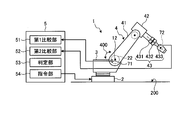
- FIG. 3 is an explanatory diagram showing a control unit of the robot.
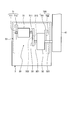
- FIG. 4 is an explanatory diagram showing a robot according to the second embodiment.
- FIG. 5 is an explanatory diagram of the first sensor and the second sensor provided in the robot according to the third embodiment.
- FIG. 1 is an explanatory diagram illustrating a work area 100 in which the robot 1 according to the first embodiment is installed.
- 2A is a schematic explanatory diagram of joints and links provided in the robot 1
- FIG. 2B is a schematic explanatory diagram showing a second joint 22 of the robot 1
- FIG. It is explanatory drawing which shows the control part.
- the robot 1 As shown in FIG. 1, the robot 1 according to the present embodiment is installed at a predetermined position in a predetermined work area 100 where an operator 6 and the like can enter and exit. Note that the installation position of the robot 1 can be set as appropriate according to the work, but here it is approximately the center position of the work area 100.
- the work area 100 is partitioned as a work booth (not shown) in a production line such as a factory.
- the robot 1 includes a base 2 installed on a floor 200 and an arm portion 4 attached to the base 2.
- the arm part 4 includes a turning part 40 that is turnable with respect to the base 2, a first arm 41 that is sequentially connected via a shaft, a second arm 42, a first wrist part 431, and a second wrist part 4.
- a wrist part 43 including a wrist part 432 and a third wrist part 433 and a rotating flange part 44 are provided.
- An end effector (not shown) suitable for the work content given to the robot 1 is attached to the flange portion 44.
- the robot 1 is composed of an articulated robot having the body part 3, the first arm 41, the second arm 42, and the wrist part 43 as movable parts.
- the robot 1 is an articulated robot including a first joint portion 21 to a sixth joint portion 26, and a movable part can be rotated around an axis.
- each of the first joint portion 21 to the sixth joint portion 26 is configured as an actuator having a servo motor and a speed reducer.
- the general configuration of the first joint portion 21 to the sixth joint portion 26 is common, and the configuration of each of the first joint portions 21 to 26 will be described with reference to FIG. 2A.
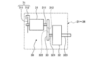
- each of the first joint portion 21 to the sixth joint portion 26 includes a transmission mechanism 30 having a motor 31 and a speed reducer 32.
- the motor 31 and the speed reducer 32 are interlocked by winding a belt 33 between an output side pulley 312 provided on the output shaft 311 of the motor 31 and an input side pulley 322 provided on the input shaft 321 of the speed reducer 32. Connected.
- FIG. 2B shows a second joint portion 22 provided on one side portion of the body portion 3 and rotatably connecting a first arm 41 that is a link body.
- the first arm 41 is fixed to the output shaft 323 of the speed reducer 32, and the first arm 41 is rotated by driving the motor 31. That is, the first arm 41 is rotated around the second shaft 12 by the transmission mechanism 30, that is, swings up and down (see the arrow 400 in FIG. 1).
- each motor 31 of the first joint part 21 to the sixth joint part 26 is provided with an encoder 71 for detecting the rotation state thereof.
- the encoder 71 includes a disk 711 attached to the rear end of the output shaft 311 and a detector 712 that detects the rotation angle of the output shaft 311 according to the amount of rotation of the disk 711.
- the trunk portion 3 is rotatably connected to the substantially cylindrical base 2 installed in a fixed state on the floor 200 via the first joint portion 21.
- the first joint portion 21 is provided at the approximate center of the base 2 and includes a first shaft 11 extending in the vertical direction (Z direction).
- shaft 11 is interlockingly connected with the 1st transmission mechanism (refer the transmission mechanism 30 of FIG. 2A) provided with a 1st motor and a 1st reduction gear.
- the body portion 3 rotates in the horizontal direction around the first axis 11 by the first transmission mechanism with respect to the base 2 fixed to the floor 200 (see arrow 300).
- the second joint portion 22 is provided on one side portion of the body portion 3, and the first arm 41 is rotatably connected via the second joint portion 22. Since the first arm 41 is coupled to the first shaft 11 at an eccentric position, the first arm 41 includes the first arm 41, and the second arm 42 is sequentially coupled to the first arm 41 via the shaft. The part 43 also turns around the first axis 11.
- a third joint portion 23 is provided on the distal end side of the longest first arm 41 in the movable portion, and a substantially L-shaped second arm 42 is connected through the third joint portion 23. ing.
- the third joint portion 23 includes a third shaft 13 extending in a direction parallel to the second shaft 12, that is, in the same direction as the second shaft 12 orthogonal to the first shaft 11. And this 3rd axis
- shaft 13 is interlockingly connected with the 3rd transmission mechanism (refer the transmission mechanism 30 of FIG. 2A) provided with a 3rd motor and a 3rd reduction gear.
- the second arm 42 rotates around the third shaft 13 by the third transmission mechanism, that is, swings up and down (see arrow 500).
- a fourth joint portion 24 is provided at the distal end side of the second arm 42, and the first wrist portion 431 is connected via the fourth joint portion 24.
- the wrist part 43 includes a cylindrical first wrist part 431 coupled to the fourth joint part 24, a second wrist part 432 coupled to the first wrist part 431, and a third wrist part provided with an end effector. 433.
- the fourth joint portion 24 that interlocks and connects the first wrist portion 431 includes a fourth shaft 14 that extends in a direction orthogonal to the third shaft 13, that is, a horizontal horizontal direction (X direction) on the drawing. And this 4th axis
- shaft 14 is interlockingly connected with the 4th transmission mechanism (refer the transmission mechanism 30 of FIG. 2A) provided with a 4th motor and a 4th reduction gear.
- the first wrist portion 431 interlocked and coupled to the fourth shaft 14 in the coaxial direction rotates around the fourth shaft 14 by the fourth transmission mechanism, that is, rotates around the fourth shaft 14 (the arrow 600 is rotated). reference).
- the 5th joint part 25 is provided in the front end side of the 1st wrist part 431, and the 2nd wrist part 432 is connected to the coaxial direction via this 5th joint part 25.
- the fifth joint portion 25 includes a fifth shaft 15 that extends coaxially with the fourth shaft 14, that is, in the horizontal direction (X direction) in the drawing. And this 5th axis
- shaft 15 is interlockingly connected with the 5th transmission mechanism (refer the transmission mechanism 30 of FIG. 2A) provided with a 5th motor and a 5th reduction gear. Therefore, the second wrist portion 432 that is interlocked and coupled to the fifth shaft 15 in the coaxial direction rotates around the fifth shaft 15 by the fifth transmission mechanism, that is, rotates around the fifth shaft 15 (the arrow 700 is rotated). reference).
- the 6th joint part 26 is provided in the tip side of the 2nd list part 432, and the 3rd list part 433 is connected via this 6th joint part 26.
- the sixth joint portion 26 includes a sixth shaft 16 extending in a direction orthogonal to the fifth shaft 15, that is, a front-rear horizontal direction (Y direction) on the drawing. And this 6th axis
- shaft 16 is interlockingly connected with the 6th transmission mechanism (refer the transmission mechanism 30 of FIG. 2A) provided with a 6th motor and a 6th reduction gear. Therefore, the third wrist 433 is rotated around the sixth shaft 16 by the sixth transmission mechanism, that is, swings in the vertical direction (see the arrow 800).
- the robot 1 includes the body portion 3 that is rotatably provided around the first axis 11 with respect to the base 2 that is provided on the floor 200 that is a predetermined installation surface. And an arm portion 4 provided to be rotatable with respect to the body portion 3.
- the arm portion 4 includes a first arm 41 provided to be rotatable about the second axis 12 with respect to the body portion 3, and a first arm 41 provided to be rotatable about the third axis 13 with respect to the first arm 41.
- Two arms 42 and a wrist 43 provided rotatably with respect to the second arm 42 are provided.
- the list unit 43 includes a first list unit 431, a second list unit 432, and a third list unit 433.
- the first wrist 431 is provided to be rotatable around the fourth axis 14 with respect to the second arm 42.
- the second list part 432 is provided to be rotatable around the fifth axis 15 with respect to the first list part 431.
- the third wrist 433 is provided to be rotatable around the sixth axis 16 with respect to the second wrist 432, and a predetermined end effector is attached to the tip.
- the body part 3, the first arm 41, the second arm 42, the first wrist part 431, the second wrist part 432, and the third wrist part 433 are a plurality of link bodies that are rotatably connected around an axis. Yes, it constitutes the movable part of the robot 1. Then, the motor provided in each transmission mechanism rotates the link body around each axis (first axis 11 to sixth axis 16).
- the robot 1 includes a first sensor that detects the rotational state of the motor and a second sensor that detects the rotational state of the link body.
- a first sensor that detects the rotational state of the motor
- a second sensor that detects the rotational state of the link body.
- an encoder 71 as a first sensor for detecting a rotation state of a second motor 31 provided in the second joint portion 22 and a first arm 41 as a link body.
- an acceleration sensor 72 which is a second sensor for detecting the rotation state.
- the encoder 71 as the first sensor includes the disk 711 attached to the rear end of the output shaft 311 and the detector 712 that detects the rotation angle of the output shaft 311 according to the amount of rotation of the disk 711. I have.
- the drive control of the second motor 31 is performed by the control unit 5 described later based on the output value from the encoder 71.
- the rotation operation of the first arm 41 is controlled based on the first information indicating the rotation angle of the output shaft 311 from the encoder 71.
- the encoder 71 is similarly provided in the first joint portion 21 and the third joint portion 23 to the sixth joint portion 26, and is used for controlling each motor.
- the acceleration sensor 72 as the second sensor is built in the middle of the first arm 41 and can detect a change in position due to acceleration of the first arm 41.
- a semiconductor type, an optical type, or a mechanical type sensor can be adopted as appropriate.
- the acceleration sensor 72 is used as the second sensor, either a speed sensor or a strain sensor can be used instead. That is, the second sensor may be a sensor that can detect the actual operation of the link body (here, the first arm 41) whose operation is controlled based on the output value from the encoder 71 by a method different from that of the encoder 71. That's fine.
- the robot 1 includes a control unit 5 that controls the operation of the robot 1 as shown in FIG.
- the control unit 5 stores a control command program for the robot 1 in advance, and the robot 1 is controlled based on the program.
- the control unit 5 is a main part of the robot 1 according to the present embodiment, and the configuration thereof will be described below.
- the control unit 5 is electrically connected to the robot 1 and includes a storage unit such as a CPU (Central Processing Unit), a ROM (Read Only Memory), a RAM (Random Access Memory), and a hard disk (not shown). .
- the CPU reads out the program stored in the storage unit, and the body unit 3, the first arm 41, the second arm 42, the first list unit 431, and the second list unit 432, which are link bodies, are read according to the program.
- the third list unit 433 is driven. That is, the driving of the motor that rotationally drives each link body is controlled.
- control part 5 is provided with the 1st comparison part 51, the 2nd comparison part 52, the determination part 53, and the instruction
- the command unit 54 outputs a command signal to, for example, the second motor 31 based on a program stored in the storage unit. At this time, the control unit 5 performs feedback control based on the first information transmitted from the encoder 71.
- the first comparison unit 51 compares the first information received from the encoder 71 with the expected value corresponding to the command signal for the second motor 31.
- the second comparison unit 52 compares the second information received from the acceleration sensor 72 with the expected value corresponding to the command signal.
- the determination unit 53 determines the operating state of at least one of the encoder 71 and the acceleration sensor 72 based on the comparison results of the first comparison unit 51 and the second comparison unit 52.
- the control unit 5 when driving the first arm 41, the control unit 5 outputs a command signal for driving the second motor 31. Then, the controller 5 determines the rotation state of the second motor 31 driven in response to the command signal from the first information based on the rotation angle of the second motor 31 detected by the encoder 71, that is, from the encoder 71. Judgment from received signal.
- the determination at this time is performed using the first comparison table stored in the first comparison unit 51 in advance.
- the data that the encoder 71 should detect and output to the control unit 5 corresponds to the command signal. It is memorized as an expected value.
- the control unit 5 compares the first information obtained from the received signal actually output from the encoder 71 with the expected value of the first comparison table. Then, the control unit 5 stores a flag indicating normality in a predetermined storage area if within a predetermined error range, and stores a flag indicating abnormality in a predetermined storage area when deviating from the predetermined error range. To store.
- the acceleration sensor 72 detects the first arm 41 that should be output to the control unit 5. Data indicating the operation result is stored as an expected value associated with the command signal.
- the control unit 5 compares the second information obtained from the reception signal actually output from the acceleration sensor 72 with the expected value of the second comparison table. Then, the control unit 5 stores a flag indicating normality in a predetermined storage area if within a predetermined error range, and stores a flag indicating abnormality in a predetermined storage area when deviating from the predetermined error range. To store.
- control unit 5 associates the comparison result obtained using the first comparison table via the encoder 71 and the comparison result obtained using the second comparison table via the acceleration sensor 72. Compare. From the comparison result, it is possible to more accurately determine whether or not at least the encoder 71 is abnormal.
- control unit 5 controls the operation of the first arm 41 based on the output of the encoder 71, but the actual operation of the first arm 41 whose operation is controlled based on the output value from the encoder 71. The result is detected by a method different from that of the encoder 71.
- the abnormality can be detected effectively. Therefore, when an abnormality is detected, it is possible to take appropriate measures such as stopping the driving of the first arm 41.
- control unit 5 double-monitors the driving status of the second motor 31 and can further improve the reliability as a human-symbiotic robot.
- the acceleration sensor 72 that is the second sensor is provided on the first arm 41 that is driven by the second motor 31 that includes the encoder 71 that is the first sensor.
- the acceleration sensor 72 which is the second sensor can be provided not only for the second motor 31 but also for each link body driven by each other motor.
- the acceleration sensor 72 as the second sensor can be provided in the body part 3, the second arm 42, the first list part 431, the second list part 432, and the third list part 433.
- the control unit 5 is provided with at least a first comparison unit 51 and a second comparison unit 52 in association with each motor.
- FIG. 4 is an explanatory diagram showing the robot 1 according to the second embodiment.
- the same components as those of the robot 1 according to the first embodiment described above are denoted by the same reference numerals, and detailed description of the components is omitted.
- the robot 1 is provided with an acceleration sensor 72 as a second sensor at the distal end of the link body positioned at the forefront with respect to the base 2. That is, the acceleration sensor 72 is provided in the third wrist part 433 that forms the tip part of the arm part 4 that is sequentially connected via the shaft.
- the acceleration sensor 72 in the third wrist part 433 By providing the acceleration sensor 72 in the third wrist part 433, the movement of the tip of the arm part 4 that is directly connected to the work purpose of the robot 1 can be detected. That is, as an operation result of the robot 1 based on the command signal from the control unit 5, data indicating a normal operation result of the third list unit 433 is set as an expected value associated with the command signal. Then, this expected value is compared with the second information obtained from the received signal actually received from the acceleration sensor 72.
- the robot 1 by detecting the comparison results of the first comparison unit 51 and the second comparison unit 52, detection when there is an abnormality in any of the plurality of encoders 71 is performed. This can be realized with the minimum number of second sensors.
- FIG. 5 is an explanatory diagram of a first sensor and a second sensor provided in the robot 1 according to the third embodiment. Also in this embodiment, the second joint portion 22 is illustrated, and the same components as those in the first and second embodiments described above are indicated by the same reference numerals, and the specific description of the components is given. Is omitted.
- the second sensor has been described as one of a speed sensor, an acceleration sensor, and a strain sensor.
- the second sensor for detecting the rotation state of the first arm 41 which is a link body the encoder is the same as the first sensor.
- a secondary encoder 720 as a second sensor is disposed on the lower side of the second reduction gear 32 with respect to the primary encoder 71 provided in the second motor 31.
- the secondary encoder 720 includes a disk 721 attached to the output shaft 323 of the second speed reducer 32 and a detector 722 that detects the rotation angle of the output shaft 323 according to the amount of rotation of the disk 721. .
- the primary control of the second motor 31 is the encoder 71 on the primary side.
- the control unit 5 uses the first comparison table to obtain the comparison result via the primary encoder 71 and the comparison result obtained via the secondary encoder 720 obtained using the second comparison table. And compare. From the comparison result, it is possible to determine the operating state of at least one of the primary-side encoder 71 and the secondary-side encoder 720.
Landscapes
- Engineering & Computer Science (AREA)
- Robotics (AREA)
- Mechanical Engineering (AREA)
- Human Computer Interaction (AREA)
- Physics & Mathematics (AREA)
- General Physics & Mathematics (AREA)
- Automation & Control Theory (AREA)
- Manipulator (AREA)
Abstract
より安全性が向上したロボットを提供する。軸周りに回転自在に連結された1以上のリンク体と、リンク体を軸周りに回転させるモータと、モータの回転状態を検出する第1のセンサと、リンク体の回転状態を検出する第2のセンサとを備える。また、ロボットは、第1のセンサからの情報に基づいてリンク体の回転を制御する制御部を備える。制御部は、第1のセンサからの第1の情報と第2のセンサからの第2の情報とに基づいて、第1のセンサおよび第2のセンサの少なくとも一方の動作状態を判断する。
Description
開示の実施形態は、ロボットに関する。
従来、軸周りに回転自在に連結された複数のリンク体を備えたロボットがあり、かかるロボットにおいて、人間を含む他物体と同じ場所で作業を行う、いわゆる人共存型と呼ばれるロボットが知られている(たとえば、特許文献1を参照)。
このような人共存型ロボットは、リンク体の人への干渉回避や、仮に接触したとしても相手にダメージを与えないことが求められる。したがって、人と接触しても人へダメージを与えることがないように、リンク体の動作制御を行うようにしていた。
しかしながら、上述した従来の人共存型と呼ばれるロボットにおけるリンク体の動作制御は、リンク体を駆動するモータに付設されたエンコーダの出力への依存度合いが大きいという課題がある。人共存型のロボットとしては、非常の事態であっても安全性をより高めることのできる動作制御の実現が望ましい。
実施形態の一態様は、上記に鑑みてなされたものであって、より安全性が向上したロボットを提供することを目的とする。
実施形態の一態様に係るロボットは、軸周りに回転自在に連結された1以上のリンク体と、前記リンク体を前記軸周りに回転させるモータと、前記モータの回転状態を検出する第1のセンサと、前記リンク体の回転状態を検出する第2のセンサとを備える。また、ロボットは、前記第1のセンサからの情報に基づいて前記リンク体の回転を制御する制御部を備える。前記制御部は、前記第1のセンサからの第1の情報と前記第2のセンサからの第2の情報とに基づいて、前記第1のセンサおよび前記第2のセンサの少なくとも一方の動作状態を判断する。
実施形態の一態様によれば、アームの動作をより確実に制御することが可能となる。
以下、添付図面を参照して、本願の開示するロボットの実施形態を詳細に説明する。なお、以下に示す実施形態によりこの発明が限定されるものではない。
(第1の実施形態)
図1は、第1の実施形態に係るロボット1が設置された作業エリア100を示す説明図である。また、図2Aは、同ロボット1が備える関節部とリンク体の模式的説明図、図2Bは、同ロボット1の第2関節部22を示す模式的説明図、図3は、同ロボット1の制御部5を示す説明図である。
図1は、第1の実施形態に係るロボット1が設置された作業エリア100を示す説明図である。また、図2Aは、同ロボット1が備える関節部とリンク体の模式的説明図、図2Bは、同ロボット1の第2関節部22を示す模式的説明図、図3は、同ロボット1の制御部5を示す説明図である。
本実施形態に係るロボット1は、図1に示すように、作業者6なども出入り可能な所定の作業エリア100の所定位置に設置される。なお、ロボット1の設置位置としては、作業に応じて適宜設定することができるが、ここでは作業エリア100の略中央位置としている。また、作業エリア100は、例えば、工場などの製造ラインにおいては作業ブース(不図示)として区画されている。
図1に示すように、ロボット1は、フロア200上に設置された基台2と、この基台2に取付けられたアーム部4とを備える。
アーム部4は、基台2に対して旋回自在の設けられる旋回部40と、それぞれ軸を介して順次連結される第1アーム41と、第2アーム42と、第1リスト部431、第2リスト部432および第3リスト部433からなるリスト部43と、回転するフランジ部44とを備えている。そして、フランジ部44にはロボット1に与えられた作業内容に適したエンドエフェクタ(不図示)が取り付けられる。
このように、本実施形態に係るロボット1は、胴体部3、第1アーム41、第2アーム42、およびリスト部43を可動部位とする多関節ロボットで構成されている。
ロボット1は、以下に説明するように、第1関節部21~第6関節部26を備えた多関節ロボットであり、可動部位を軸周りに回転可能としている。
図2Aに示すように、第1関節部21~第6関節部26は、いずれもサーボモータ及び減速機を有するアクチュエータとして構成されている。第1関節部21~第6関節部26の概ねの構成は共通しており、図2A参照して第1関節部21~26それぞれの構成について説明する。
図2Aに示すように、第1関節部21~第6関節部26は、それぞれモータ31と減速機32とを有する伝動機構30を備えている。モータ31と減速機32とは、モータ31の出力軸311に設けた出力側プーリ312と、減速機32の入力軸321に設けた入力側プーリ322との間にベルト33を巻装して連動連結される。
図2Bは、胴体部3の一側部分に設けられ、リンク体である第1アーム41を回転可能に連結した第2関節部22を示している。図2Bに示すように、減速機32の出力軸323に第1アーム41が固着され、モータ31の駆動によって第1アーム41が回転される。すなわち、第1アーム41は、伝動機構30により、第2軸12周りに回転、つまり、上下方向に揺動する(図1の矢印400を参照)。
ところで、第1関節部21~第6関節部26の各モータ31には、その回転状態を検出するエンコーダ71が設けられている。このエンコーダ71は、出力軸311の後端に取付けたディスク711と、ディスク711の回転量に応じて出力軸311の回転角度を検出する検出器712とを備えている。
次に、前述の第2関節部22をはじめとする関節部を介してそれぞれ軸周りに回転する可動部位について、図1に基づいて簡単に説明する。
胴体部3は、フロア200に固定状態に設置された略円筒状の基台2に対し、第1関節部21を介して回転可能に連結されている。第1関節部21は、基台2の略中央に設けられており、垂直方向(Z方向)に延在する第1軸11を備えている。
そして、この第1軸11を、第1のモータと第1の減速機とを備える第1の伝動機構(図2Aの伝動機構30を参照)に連動連結している。こうして、胴体部3は、フロア200に固定された基台2に対して、第1の伝動機構により、第1軸11周りに水平方向に回転することになる(矢印300を参照)。
また、胴体部3の一側部分には、前述したように第2関節部22が設けられており、この第2関節部22を介して第1アーム41が回転可能に連結されている。なお、かかる第1アーム41は、第1軸11に偏心した位置に連結されているため、この第1アーム41を含み、これにそれぞれ軸を介して順次連結される第2アーム42、およびリスト部43についても第1軸11を中心に旋回することになる。
可動部位の中で最も長尺な第1アーム41の先端側には第3関節部23が設けられており、この第3関節部23を介して略L字状の第2アーム42が連結されている。
第3関節部23は、第2軸12と平行方向、すなわち、第1軸11と直交する第2軸12と同方向に延在する第3軸13を備えている。そして、この第3軸13は、第3のモータと第3の減速機とを備える第3の伝動機構(図2Aの伝動機構30を参照)に連動連結している。こうして、第2アーム42は、第3の伝動機構により、第3軸13周りに回転、つまり、上下方向に揺動する(矢印500を参照)。
また、第2アーム42の先端側には第4関節部24が設けられており、この第4関節部24を介して、第1リスト部431が連結されている。
なお、リスト部43は、第4関節部24に連結する円筒状の第1リスト部431と、この第1リスト部431に連結する第2リスト部432と、エンドエフェクタを設けた第3リスト部433とから構成される。
第1リスト部431を連動連結する第4関節部24は、第3軸13と直交する方向、すなわち、図面上の左右水平方向(X方向)に延在する第4軸14を備えている。そして、この第4軸14は、第4のモータと第4の減速機とを備える第4の伝動機構(図2Aの伝動機構30を参照)に連動連結している。こうして、第4軸14と同軸方向に連動連結された第1リスト部431は、第4の伝動機構により、第4軸14周りに回転、つまり、第4軸14周りに自転する(矢印600を参照)。
第1リスト部431の先端側には、第5関節部25が設けられており、この第5関節部25を介して、第2リスト部432が同軸方向に連結されている。
第5関節部25は、第4軸14と同軸方向、すなわち、図面上の左右水平方向(X方向)に延在する第5軸15を備えている。そして、この第5軸15は、第5のモータと第5の減速機とを備える第5の伝動機構(図2Aの伝動機構30を参照)に連動連結している。したがって、第5軸15と同軸方向に連動連結された第2リスト部432は、第5の伝動機構により、第5軸15周りに回転、つまり、第5軸15周りに自転する(矢印700を参照)。
第2リスト部432の先端側には、第6関節部26が設けられており、この第6関節部26を介して、第3リスト部433が連結されている。
第6関節部26は、第5軸15と直交する方向、すなわち、図面上の前後水平方向(Y方向)に延在する第6軸16を備えている。そして、この第6軸16は、第6のモータと第6の減速機とを備える第6の伝動機構(図2Aの伝動機構30を参照)に連動連結している。したがって、第3リスト部433は、第6の伝動機構により、第6軸16周りに回転、つまり、上下方向に揺動する(矢印800を参照)。
上述してきたように、本実施形態に係るロボット1は、所定の設置面であるフロア200に設けられる基台2に対して第1軸11周りに回転可能に設けられた胴体部3と、この胴体部3に対して回転可能に設けられたアーム部4とを備えている。
アーム部4は、胴体部3に対して第2軸12周りに回転可能に設けられた第1アーム41と、この第1アーム41に対して第3軸13周りに回転可能に設けられた第2アーム42と、第2アーム42に対して回転可能に設けられたリスト部43とを備えている。
また、リスト部43は、第1リスト部431と第2リスト部432と第3リスト部433とを備えている。第1リスト部431は、第2アーム42に対して第4軸14周りに回転可能に設けられている。第2リスト部432は、第1リスト部431に対して第5軸15周りに回転可能に設けられている。また、第3リスト部433は、第2リスト部432に対して第6軸16周りに回転可能に設けられるとともに、先端には所定のエンドエフェクタが取り付けられている。
これらの胴体部3、第1アーム41、第2アーム42、第1リスト部431、第2リスト部432、および第3リスト部433は、軸周りに回転自在に連結された複数のリンク体であり、ロボット1の可動部位を構成することになる。そして、かかるリンク体を、各伝動機構にそれぞれ設けられたモータが各軸(第1軸11~第6軸16)周りに回転させる。
また、本実施形態に係るロボット1は、モータの回転状態を検出する第1のセンサと、リンク体の回転状態を検出する第2のセンサとをそなえている。具体的には、図2に示すように、第2関節部22に設けられた第2のモータ31の回転状態を検出する第1のセンサとしてのエンコーダ71と、リンク体である第1アーム41の回転状態を検出する第2のセンサである加速度センサ72とを備えている。
第1のセンサであるエンコーダ71は、前述したように、出力軸311の後端に取付けたディスク711と、ディスク711の回転量に応じて出力軸311の回転角度を検出する検出器712とを備えている。
本実施形態に係るロボット1は、エンコーダ71からの出力値に基づき、後述する制御部5によって第2のモータ31の駆動制御が行われる。つまり、第1アーム41を例にとると、この第1アーム41の回転動作の制御は、エンコーダ71からの出力軸311の回転角度を示す第1の情報に基づいて行われる。かかるエンコーダ71は、第1関節部21、第3関節部23~第6関節部26においても同じように設けられており、各モータの制御に用いられる。
また、第2のセンサである加速度センサ72は、第1アーム41の中途に内蔵されて、当該第1アーム41の加速による位置変化を検出することができる。加速度センサ72としては、半導体式、光学式、機械式のセンサから適宜採用することができる。
また、第2のセンサとして、加速度センサ72を用いたが、これに代えて、速度センサまたは歪センサのいずれかを用いることもできる。すなわち、第2のセンサは、エンコーダ71からの出力値に基づいて動作制御されるリンク体(ここでは第1アーム41)の実際の動作を、エンコーダ71とは異なる方式で検出可能なセンサであればよい。
本実施形態に係るロボット1は、図3に示すように、当該ロボット1の動作を制御する制御部5を備えている。この制御部5には、ロボット1への制御指令のプログラムが予め記憶されており、かかるプログラムに基づいて、ロボット1は制御されることになる。かかる制御部5は、本実施形態に係るロボット1の要部となるものであり、以下にその構成を説明する。
制御部5は、ロボット1と電気的に接続しており、図示しないCPU(Central Processing Unit)やROM(Read Only Memory)、RAM(Random Access Memory)、さらにはハードディスクなどの記憶部を備えている。そして、制御部5は、記憶部に格納されたプログラムをCPUが読み出し、プログラムに従ってリンク体である胴体部3、第1アーム41、第2アーム42、第1リスト部431、第2リスト部432、および第3リスト部433を駆動する。すなわち、各リンク体を回転駆動させるモータの駆動を制御する。
また、制御部5は、図3に示すように、第1比較部51と、第2比較部52と、判定部53と、指令部54とを備えている。この指令部54は、記憶部に記憶されたプログラムに基づいて、例えば第2のモータ31へ指令信号を出力する。このとき、制御部5では、エンコーダ71から送信される第1の情報に基づくフィードバック制御を行う。
また、第1比較部51は、エンコーダ71から受信した第1の情報と、第2のモータ31に対する指令信号に対応する期待値とを比較する。第2比較部52は、加速度センサ72から受信した第2の情報と、指令信号に対応する期待値とを比較する。判定部53は、第1比較部51および第2比較部52の各比較結果に基づいて、エンコーダ71および加速度センサ72の少なくとも一方の動作状態を判断する。
例えば、第1アーム41を駆動させる場合、制御部5は、第2のモータ31を駆動するための指令信号を出力する。そして、かかる指令信号を受けて駆動した第2のモータ31の回転状態を、制御部5は、エンコーダ71が検出した第2のモータ31の回転角度に基づく第1の情報、すなわちエンコーダ71からの受信信号から判断する。
本実施形態における制御部5では、このときの判断を、第1比較部51に予め格納された第1比較テーブルを用いて行う。
すなわち、第1比較テーブルに、指令信号に基づいて第2のモータ31が正常に回転駆動した場合、エンコーダ71が検出して制御部5に対して出力されるはずのデータを、指令信号に対応付けられた期待値として記憶させておく。
制御部5は、エンコーダ71から実際に出力されてきた受信信号により得た第1の情報と第1比較テーブルの期待値とを比較する。そして、制御部5は、所定の誤差範囲内であれば、正常を示すフラグを所定の記憶領域に格納し、所定の誤差範囲から逸脱している場合は、異常を示すフラグを所定の記憶領域に格納する。
一方、第2比較テーブルには、指令信号に基づいて第2のモータ31が正常に回転駆動した場合、加速度センサ72が検出して制御部5に対して出力されるはずの第1アーム41の動作結果を示すデータを、指令信号に対応付けられた期待値として記憶させておく。
制御部5は、加速度センサ72から実際に出力されてきた受信信号により得た第2の情報と第2比較テーブルの期待値とを比較する。そして、制御部5は、所定の誤差範囲内であれば、正常を示すフラグを所定の記憶領域に格納し、所定の誤差範囲から逸脱している場合は、異常を示すフラグを所定の記憶領域に格納する。
こうして、制御部5は、第1比較テーブルを用いて得た、エンコーダ71を介した比較結果と、第2比較テーブルを用いて得た、加速度センサ72を介して得た比較結果とを付き合わせて比較する。そして、その比較した結果から、少なくともエンコーダ71に異常があるか否かをより正確に判断することが可能となる。
このように、制御部5は、エンコーダ71の出力に基づいて第1アーム41の動作制御を行っているが、エンコーダ71からの出力値に基づいて動作制御される第1アーム41の実際の動作結果を、エンコーダ71とは異なる方式で検出している。
したがって、エンコーダ71および加速度センサ72のいずれか一方、または双方に異常があった場合、かかる異常を効果的に検出することができる。そのため、異常を検出した場合、第1アーム41の駆動を停止するなど、適切な対応が可能となる。
すなわち、制御部5は、第2のモータ31の駆動状況を二重で監視することになり、人共存型のロボットとしての信頼性をより向上させることができる。
上述してきたロボット1では、第2のセンサである加速度センサ72を、第1のセンサであるエンコーダ71を備える第2のモータ31により駆動される第1アーム41に設けていた。しかし、第2のセンサである加速度センサ72は、第2のモータ31のみならず、その他の各モータによって駆動される各リンク体にそれぞれ対応して設けることもできる。
すなわち、第2のセンサである加速度センサ72は、胴体部3、第2アーム42、第1リスト部431、第2リスト部432、および第3リスト部433にそれぞれ設けることができる。
このように、加速度センサ72(第2のセンサ)を各リンク体にそれぞれ対応して設ければ、どのリンク体に対応するエンコーダ71、あるいは加速度センサ72に異常があると考えられるのかが特定できる。なお、この場合、制御部5は、各モータ毎に、少なくとも、第1比較部51と第2比較部52とを対応付けて設けておくこととする。
(第2の実施形態)
図4は、第2の実施形態に係るロボット1を示す説明図である。なお、本実施形態では前述してきた第1の実施形態に係るロボット1と同じ構成要素については同じ符号を用いて示し、構成要素の具体的な説明は省略する。
図4は、第2の実施形態に係るロボット1を示す説明図である。なお、本実施形態では前述してきた第1の実施形態に係るロボット1と同じ構成要素については同じ符号を用いて示し、構成要素の具体的な説明は省略する。
図4に示すように、本実施形態に係るロボット1は、第2のセンサである加速度センサ72を、基台2に対して最先端に位置するリンク体の先端部に設けている。すなわち、軸を介して順次連結されるアーム部4の先端部をなす第3リスト部433に加速度センサ72を設けている。
加速度センサ72を第3リスト部433に設けることにより、ロボット1の作業目的に直結するアーム部4の先端の動きが検出できる。すなわち、制御部5からの指令信号に基づいたロボット1の動作結果として、第3リスト部433の正常な動作結果を示すデータを指令信号に対応付けられた期待値とする。そして、この期待値と、実際に加速度センサ72から受信した受信信号により得た第2の情報とを比較するのである。
本実施形態に係るロボット1によれば、第1比較部51および第2比較部52の各比較結果を付き合わせることで、複数のエンコーダ71のうちのいずれかに異常がある場合の検出を、最少個数の第2のセンサで実現することが可能となる。
(第3の実施形態)
図5は、第3の実施形態に係るロボット1が備える第1のセンサおよび第2のセンサの説明図である。なお、本実施形態においても、第2関節部22を例示しており、前述してきた第1、第2の実施形態と同じ構成要素については同じ符号を用いて示し、構成要素の具体的な説明は省略する。
図5は、第3の実施形態に係るロボット1が備える第1のセンサおよび第2のセンサの説明図である。なお、本実施形態においても、第2関節部22を例示しており、前述してきた第1、第2の実施形態と同じ構成要素については同じ符号を用いて示し、構成要素の具体的な説明は省略する。
上述してきた実施形態では、第2のセンサを、速度センサ、加速度センサ、または歪センサのうちのいずれかとして説明した。しかし、ここでは、リンク体である第1アーム41の回転状態を検出する第2のセンサとして、第1のセンサと同じくエンコーダとしている。
すなわち、図示するように、第2のモータ31に設けた一次側のエンコーダ71に対し、第2の減速機32の下手側に、第2のセンサとしての二次側のエンコーダ720を配設している。二次側のエンコーダ720は、第2の減速機32の出力軸323に取付けたディスク721と、ディスク721の回転量に応じて出力軸323の回転角度を検出する検出器722とを備えている。
この場合においても、第2のモータ31の制御の基は一次側のエンコーダ71である。制御部5は、第1比較テーブルを用いて得た、一次側のエンコーダ71を介した比較結果と、第2比較テーブルを用いて得た、二次側のエンコーダ720を介して得た比較結果とを付き合わせて比較する。そして、その比較した結果から、一次側のエンコーダ71および二次側のエンコーダ720の少なくとも一方の動作状態を判断することが可能となる。
さらなる効果や変形例は、当業者によって容易に導き出すことができる。このため、本発明のより広範な態様は、以上のように表しかつ記述した特定の詳細および代表的な実施形態に限定されるものではない。したがって、添付の特許請求の範囲およびその均等物によって定義される総括的な発明の概念の精神または範囲から逸脱することなく、様々な変更が可能である。例えば、リンク体が単数であるものにおいても本発明を構成することがである。
1 ロボット
2 基台
3 胴体部(リンク体)
4 アーム部
5 制御部
6 作業者
22 第2関節部
31 第2のモータ
41 第1アーム(リンク体)
42 第2アーム(リンク体)
43 リスト部
51 第1比較部
52 第2比較部
53 判定部
71 エンコーダ(第1のセンサ)
72 加速度センサ(第2のセンサ)
431 第1リスト部(リンク体)
432 第2リスト部(リンク体)
433 第3リスト部(リンク体)
2 基台
3 胴体部(リンク体)
4 アーム部
5 制御部
6 作業者
22 第2関節部
31 第2のモータ
41 第1アーム(リンク体)
42 第2アーム(リンク体)
43 リスト部
51 第1比較部
52 第2比較部
53 判定部
71 エンコーダ(第1のセンサ)
72 加速度センサ(第2のセンサ)
431 第1リスト部(リンク体)
432 第2リスト部(リンク体)
433 第3リスト部(リンク体)
Claims (6)
- 軸周りに回転自在に連結された1以上のリンク体と、
前記リンク体を前記軸周りに回転させるモータと、
前記モータの回転状態を検出する第1のセンサと、
前記リンク体の回転状態を検出する第2のセンサと、
前記第1のセンサからの情報に基づいて前記リンク体の回転を制御する制御部と、
を備え、
前記制御部は、
前記第1のセンサからの第1の情報と前記第2のセンサからの第2の情報とに基づいて、前記第1のセンサおよび前記第2のセンサの少なくとも一方の動作状態を判断すること
を特徴とするロボット。 - 前記制御部は、
前記第1のセンサから受信した前記第1の情報と、前記モータに対する指令信号に対応する期待値とを比較する第1比較部と、
前記第2のセンサから受信した前記第2の情報と、前記指令信号に対応する期待値とを比較する第2比較部と、
前記第1比較部および前記第2比較部の各比較結果に基づいて、前記第1のセンサおよび前記第2のセンサの少なくとも一方の動作状態を判断する判定部と、
を備えることを特徴とする請求項1に記載のロボット。 - 前記第1のセンサは前記モータに付設されたエンコーダであり、
前記第2のセンサは、速度センサ、加速度センサ、または歪センサのうちのいずれかであること
を特徴とする請求項1または2に記載のロボット。 - 前記リンク体は、
基台から、それぞれ軸を介して順次連結されてアーム部を構成すること
を特徴とする請求項1、2または3に記載のロボット。 - 前記第2のセンサは、
前記各モータによって駆動される前記リンク体にそれぞれ対応して設けられていること
を特徴とする請求項4に記載のロボット。 - 前記第2のセンサは加速度センサであり、
前記基台に対して最先端に位置する前記リンク体の先端部に設けられていること
を特徴とする請求項4に記載のロボット。
Priority Applications (5)
| Application Number | Priority Date | Filing Date | Title |
|---|---|---|---|
| JP2014516538A JP5949911B2 (ja) | 2012-05-21 | 2012-05-21 | ロボット |
| PCT/JP2012/062948 WO2013175553A1 (ja) | 2012-05-21 | 2012-05-21 | ロボット |
| CN201280073212.1A CN104302454B (zh) | 2012-05-21 | 2012-05-21 | 机器人 |
| EP12877241.5A EP2853359B1 (en) | 2012-05-21 | 2012-05-21 | Robot |
| US14/549,453 US9266240B2 (en) | 2012-05-21 | 2014-11-20 | Robot |
Applications Claiming Priority (1)
| Application Number | Priority Date | Filing Date | Title |
|---|---|---|---|
| PCT/JP2012/062948 WO2013175553A1 (ja) | 2012-05-21 | 2012-05-21 | ロボット |
Related Child Applications (1)
| Application Number | Title | Priority Date | Filing Date |
|---|---|---|---|
| US14/549,453 Continuation US9266240B2 (en) | 2012-05-21 | 2014-11-20 | Robot |
Publications (1)
| Publication Number | Publication Date |
|---|---|
| WO2013175553A1 true WO2013175553A1 (ja) | 2013-11-28 |
Family
ID=49623286
Family Applications (1)
| Application Number | Title | Priority Date | Filing Date |
|---|---|---|---|
| PCT/JP2012/062948 WO2013175553A1 (ja) | 2012-05-21 | 2012-05-21 | ロボット |
Country Status (5)
| Country | Link |
|---|---|
| US (1) | US9266240B2 (ja) |
| EP (1) | EP2853359B1 (ja) |
| JP (1) | JP5949911B2 (ja) |
| CN (1) | CN104302454B (ja) |
| WO (1) | WO2013175553A1 (ja) |
Cited By (6)
| Publication number | Priority date | Publication date | Assignee | Title |
|---|---|---|---|---|
| WO2015131904A1 (en) * | 2014-03-04 | 2015-09-11 | Universal Robots A/S | Safety system for industrial robot |
| US10323995B2 (en) | 2017-01-06 | 2019-06-18 | Fanuc Corporation | Rotation-shaft joint structure |
| JP2019119014A (ja) * | 2018-01-05 | 2019-07-22 | 株式会社不二越 | ロボット制御装置、ロボットシステムおよびロボットアームの接触検知方法 |
| JP2021122898A (ja) * | 2020-02-05 | 2021-08-30 | 芝浦機械株式会社 | ロボットシステムおよび操作装置 |
| WO2022138801A1 (ja) * | 2020-12-23 | 2022-06-30 | パナソニックIpマネジメント株式会社 | 異常判定装置、モータ制御装置、異常判定方法およびプログラム |
| WO2023148896A1 (ja) * | 2022-02-03 | 2023-08-10 | 株式会社安川電機 | ロボットシステム及びセンシング方法 |
Families Citing this family (10)
| Publication number | Priority date | Publication date | Assignee | Title |
|---|---|---|---|---|
| KR102061693B1 (ko) * | 2013-10-07 | 2020-01-02 | 삼성전자주식회사 | 액추에이터 유닛, 이를 포함한 로봇 및 감속기 장치 |
| CN106102645B (zh) | 2014-03-17 | 2019-06-21 | 直观外科手术操作公司 | 用于与基准靶对准的系统和方法 |
| KR101734241B1 (ko) * | 2015-12-10 | 2017-05-11 | 현대자동차 주식회사 | 트렁크 리드 힌지 지능형 로더유닛 |
| CA2928413C (en) | 2016-03-31 | 2019-03-05 | Novarc Technologies Inc. | Robotic welding system |
| US9868214B2 (en) * | 2016-06-20 | 2018-01-16 | X Development Llc | Localization of a mobile system |
| JP2018122416A (ja) * | 2017-02-02 | 2018-08-09 | セイコーエプソン株式会社 | ロボット |
| CN109591050A (zh) * | 2017-09-30 | 2019-04-09 | 西门子公司 | 安全跟踪系统、装置、方法、存储介质及安全系统 |
| JP6593715B2 (ja) * | 2017-10-27 | 2019-10-23 | 株式会社安川電機 | 異常判定システム、モータ制御装置 |
| DE102020104364B3 (de) * | 2020-02-19 | 2021-05-27 | Franka Emika Gmbh | Steuerung eines Robotermanipulators bei Kontakt mit einer Person |
| TWI770496B (zh) | 2020-04-20 | 2022-07-11 | 達明機器人股份有限公司 | 機器人感測器的檢知方法 |
Citations (7)
| Publication number | Priority date | Publication date | Assignee | Title |
|---|---|---|---|---|
| JPS6450909A (en) * | 1987-08-21 | 1989-02-27 | Mitsubishi Electric Corp | Detecting device of abnormality of encoder |
| JP2001150374A (ja) * | 1999-11-25 | 2001-06-05 | Sony Corp | ロボットの故障診断システム |
| JP2002144260A (ja) * | 2000-11-13 | 2002-05-21 | Sony Corp | 脚式移動ロボット及びその制御方法 |
| JP2007007804A (ja) * | 2005-07-01 | 2007-01-18 | Toyota Motor Corp | 自律型移動ロボットの位置計測手段と方向計測手段の異常を検知する方法と、自律型移動ロボット |
| JP2008302496A (ja) | 2006-07-04 | 2008-12-18 | Panasonic Corp | ロボットアームの制御装置及び制御方法、ロボット、及びロボットアームの制御プログラム |
| JP2010064232A (ja) * | 2008-09-12 | 2010-03-25 | Yaskawa Electric Corp | 搬送システムの異常検出方法および異常検出装置 |
| JP2011224727A (ja) * | 2010-04-20 | 2011-11-10 | Fanuc Ltd | ロボットシステム |
Family Cites Families (27)
| Publication number | Priority date | Publication date | Assignee | Title |
|---|---|---|---|---|
| US5513946A (en) * | 1991-08-27 | 1996-05-07 | Canon Kabushiki Kaisha | Clean robot |
| KR100563982B1 (ko) * | 1998-10-19 | 2006-03-29 | 가부시키가이샤 야스카와덴키 | 클린 로봇의 안전 보호 장치 |
| JP3811072B2 (ja) * | 2002-01-18 | 2006-08-16 | 本田技研工業株式会社 | 移動ロボットの異常検知装置 |
| JP2005013715A (ja) * | 2003-06-05 | 2005-01-20 | Olympus Corp | 観察システム |
| JP4294646B2 (ja) * | 2003-07-29 | 2009-07-15 | パナソニック株式会社 | ロボットアームの制御方法および制御装置 |
| JP3883544B2 (ja) * | 2004-02-27 | 2007-02-21 | 株式会社東芝 | ロボット制御装置およびロボットの制御方法 |
| DE102004026185A1 (de) * | 2004-05-28 | 2005-12-22 | Kuka Roboter Gmbh | Verfahren und Vorrichtung zum Betreiben einer Maschine, wie eines Mehrachs- Industrieroboters |
| US7882394B2 (en) * | 2005-07-11 | 2011-02-01 | Brooks Automation, Inc. | Intelligent condition-monitoring and fault diagnostic system for predictive maintenance |
| US8219245B2 (en) * | 2006-05-15 | 2012-07-10 | Kuka Roboter Gmbh | Articulated arm robot |
| JP2008022590A (ja) * | 2006-07-10 | 2008-01-31 | Nachi Fujikoshi Corp | サーボモータ監視装置 |
| JP2008188722A (ja) * | 2007-02-06 | 2008-08-21 | Fanuc Ltd | ロボット制御装置 |
| JP5549129B2 (ja) * | 2009-07-06 | 2014-07-16 | セイコーエプソン株式会社 | 位置制御方法、ロボット |
| JP5685842B2 (ja) * | 2010-07-12 | 2015-03-18 | セイコーエプソン株式会社 | ロボット装置およびロボット装置の制御方法 |
| IT1401977B1 (it) * | 2010-09-28 | 2013-08-28 | C N R Consiglio Naz Ricerche | Apparecchiatura robotizzata con dispositivo di sicurezza perfezionato e metodo di controllo per la verifica in tempo reale delle grandezze cinematiche di stato dell'apparecchiatura robotizzata. |
| DE102011087958A1 (de) * | 2011-12-08 | 2013-06-13 | Kuka Roboter Gmbh | Schweißroboter |
| JP2013184236A (ja) * | 2012-03-06 | 2013-09-19 | Jtekt Corp | ロボットのキャリブレーション方法及びキャリブレーション装置 |
| JP6226559B2 (ja) * | 2012-05-30 | 2017-11-08 | キヤノン株式会社 | 超音波モータおよび、超音波モータの駆動方法 |
| JP6332900B2 (ja) * | 2012-08-31 | 2018-05-30 | セイコーエプソン株式会社 | ロボットシステム及びロボット制御装置 |
| JP6111562B2 (ja) * | 2012-08-31 | 2017-04-12 | セイコーエプソン株式会社 | ロボット |
| JP6332899B2 (ja) * | 2012-08-31 | 2018-05-30 | セイコーエプソン株式会社 | ロボット |
| JP5962340B2 (ja) * | 2012-08-31 | 2016-08-03 | セイコーエプソン株式会社 | ロボット |
| JP6111563B2 (ja) * | 2012-08-31 | 2017-04-12 | セイコーエプソン株式会社 | ロボット |
| JP6008121B2 (ja) * | 2013-01-28 | 2016-10-19 | セイコーエプソン株式会社 | ロボットおよびロボット制御装置 |
| JP6155780B2 (ja) * | 2013-04-10 | 2017-07-05 | セイコーエプソン株式会社 | ロボット、ロボット制御装置およびロボットシステム |
| JP2014205198A (ja) * | 2013-04-10 | 2014-10-30 | セイコーエプソン株式会社 | ロボット、ロボット制御装置およびロボットシステム |
| JP2014205197A (ja) * | 2013-04-10 | 2014-10-30 | セイコーエプソン株式会社 | ロボット、ロボット制御装置およびロボットシステム |
| JP2014205199A (ja) * | 2013-04-10 | 2014-10-30 | セイコーエプソン株式会社 | ロボット、ロボット制御装置およびロボットシステム |
-
2012
- 2012-05-21 WO PCT/JP2012/062948 patent/WO2013175553A1/ja active Application Filing
- 2012-05-21 EP EP12877241.5A patent/EP2853359B1/en active Active
- 2012-05-21 CN CN201280073212.1A patent/CN104302454B/zh active Active
- 2012-05-21 JP JP2014516538A patent/JP5949911B2/ja active Active
-
2014
- 2014-11-20 US US14/549,453 patent/US9266240B2/en active Active
Patent Citations (7)
| Publication number | Priority date | Publication date | Assignee | Title |
|---|---|---|---|---|
| JPS6450909A (en) * | 1987-08-21 | 1989-02-27 | Mitsubishi Electric Corp | Detecting device of abnormality of encoder |
| JP2001150374A (ja) * | 1999-11-25 | 2001-06-05 | Sony Corp | ロボットの故障診断システム |
| JP2002144260A (ja) * | 2000-11-13 | 2002-05-21 | Sony Corp | 脚式移動ロボット及びその制御方法 |
| JP2007007804A (ja) * | 2005-07-01 | 2007-01-18 | Toyota Motor Corp | 自律型移動ロボットの位置計測手段と方向計測手段の異常を検知する方法と、自律型移動ロボット |
| JP2008302496A (ja) | 2006-07-04 | 2008-12-18 | Panasonic Corp | ロボットアームの制御装置及び制御方法、ロボット、及びロボットアームの制御プログラム |
| JP2010064232A (ja) * | 2008-09-12 | 2010-03-25 | Yaskawa Electric Corp | 搬送システムの異常検出方法および異常検出装置 |
| JP2011224727A (ja) * | 2010-04-20 | 2011-11-10 | Fanuc Ltd | ロボットシステム |
Non-Patent Citations (1)
| Title |
|---|
| See also references of EP2853359A4 |
Cited By (15)
| Publication number | Priority date | Publication date | Assignee | Title |
|---|---|---|---|---|
| JP7042554B2 (ja) | 2014-03-04 | 2022-03-28 | ユニバーサル ロボッツ アクツイエセルスカプ | 安全機能を有する工業用ロボットとその安全制御のための方法 |
| CN106061688A (zh) * | 2014-03-04 | 2016-10-26 | 优傲机器人公司 | 用于工业机器人的安全系统 |
| KR20160130424A (ko) * | 2014-03-04 | 2016-11-11 | 유니버셜 로보츠 에이/에스 | 산업용 로봇을 위한 안전 시스템 |
| US20170057095A1 (en) * | 2014-03-04 | 2017-03-02 | Universal Robots A/S | Safety system for industrial robot |
| JP2017507041A (ja) * | 2014-03-04 | 2017-03-16 | ユニバーサル ロボッツ アクツイエセルスカプ | 工業用ロボットの安全システム |
| RU2688977C2 (ru) * | 2014-03-04 | 2019-05-23 | Юниверсал Роботс А/С | Система безопасности для промышленного робота |
| WO2015131904A1 (en) * | 2014-03-04 | 2015-09-11 | Universal Robots A/S | Safety system for industrial robot |
| KR102386763B1 (ko) * | 2014-03-04 | 2022-04-14 | 유니버셜 로보츠 에이/에스 | 산업용 로봇을 위한 안전 시스템 |
| US10399232B2 (en) | 2014-03-04 | 2019-09-03 | Universal Robots A/S | Safety system for industrial robot |
| US10323995B2 (en) | 2017-01-06 | 2019-06-18 | Fanuc Corporation | Rotation-shaft joint structure |
| JP7004942B2 (ja) | 2018-01-05 | 2022-01-21 | 株式会社不二越 | ロボット制御装置、ロボットシステムおよびロボットアームの接触検知方法 |
| JP2019119014A (ja) * | 2018-01-05 | 2019-07-22 | 株式会社不二越 | ロボット制御装置、ロボットシステムおよびロボットアームの接触検知方法 |
| JP2021122898A (ja) * | 2020-02-05 | 2021-08-30 | 芝浦機械株式会社 | ロボットシステムおよび操作装置 |
| WO2022138801A1 (ja) * | 2020-12-23 | 2022-06-30 | パナソニックIpマネジメント株式会社 | 異常判定装置、モータ制御装置、異常判定方法およびプログラム |
| WO2023148896A1 (ja) * | 2022-02-03 | 2023-08-10 | 株式会社安川電機 | ロボットシステム及びセンシング方法 |
Also Published As
| Publication number | Publication date |
|---|---|
| CN104302454A (zh) | 2015-01-21 |
| JPWO2013175553A1 (ja) | 2016-01-12 |
| CN104302454B (zh) | 2016-08-17 |
| EP2853359B1 (en) | 2022-07-20 |
| US9266240B2 (en) | 2016-02-23 |
| EP2853359A1 (en) | 2015-04-01 |
| US20150081095A1 (en) | 2015-03-19 |
| JP5949911B2 (ja) | 2016-07-13 |
| EP2853359A4 (en) | 2016-08-03 |
Similar Documents
| Publication | Publication Date | Title |
|---|---|---|
| JP5949911B2 (ja) | ロボット | |
| CN108858183B (zh) | 机器人、机器人的控制方法、工件的制造方法 | |
| JP7086531B2 (ja) | ロボットハンド、ロボット装置、ロボットハンドの制御方法、物品の製造方法、制御プログラム及び記録媒体 | |
| JP7042554B2 (ja) | 安全機能を有する工業用ロボットとその安全制御のための方法 | |
| WO2013175554A1 (ja) | ロボットおよびロボットシステム | |
| TWI586498B (zh) | 機器人系統及末端執行器之變形檢測方法 | |
| US11413759B2 (en) | Robot apparatus, control method for controlling the same, non-transitory computer-readable recording medium, manufacturing system, and method for manufacturing an article | |
| JP5191738B2 (ja) | マニピュレータの制御方法および制御システム | |
| WO2016103308A1 (ja) | ロボットシステム | |
| US10603798B2 (en) | Robot | |
| CN107073720A (zh) | 机械手手部以及机械手 | |
| KR20130093545A (ko) | 토크를 검출하기 위한 방법 및 산업용 로봇 | |
| JP6630739B2 (ja) | 検出装置の異常判定システム、および検出装置の異常判定方法 | |
| JP5447455B2 (ja) | ロボットおよびロボットシステム | |
| CN110678301A (zh) | 操作装置 | |
| WO2016147592A1 (ja) | ロボット、ロボットの制御方法、ワークの取付方法及びワークの搬送方法 | |
| JP2018126818A (ja) | ロボット制御装置 | |
| US10035265B2 (en) | Manipulator | |
| JP6391252B2 (ja) | ロボット装置 | |
| US20200070341A1 (en) | Robot and robot system | |
| US20220241973A1 (en) | Robot Control Device And Robot System | |
| WO2013140514A1 (ja) | 作業ロボットおよびロボットシステム | |
| JP2010249585A (ja) | 現在位置特定装置及び現在位置特定方法 | |
| JP2016120537A (ja) | マニピュレータ装置及び駆動制御プログラム | |
| JP7414426B2 (ja) | ロボットシステム |
Legal Events
| Date | Code | Title | Description |
|---|---|---|---|
| 121 | Ep: the epo has been informed by wipo that ep was designated in this application |
Ref document number: 12877241 Country of ref document: EP Kind code of ref document: A1 |
|
| ENP | Entry into the national phase |
Ref document number: 2014516538 Country of ref document: JP Kind code of ref document: A |
|
| WWE | Wipo information: entry into national phase |
Ref document number: 2012877241 Country of ref document: EP |
|
| NENP | Non-entry into the national phase |
Ref country code: DE |