WO2024009453A1 - 転がり軸受装置 - Google Patents
転がり軸受装置 Download PDFInfo
- Publication number
- WO2024009453A1 WO2024009453A1 PCT/JP2022/026957 JP2022026957W WO2024009453A1 WO 2024009453 A1 WO2024009453 A1 WO 2024009453A1 JP 2022026957 W JP2022026957 W JP 2022026957W WO 2024009453 A1 WO2024009453 A1 WO 2024009453A1
- Authority
- WO
- WIPO (PCT)
- Prior art keywords
- ring
- inner ring
- extending
- relay
- oil seal
- Prior art date
- Legal status (The legal status is an assumption and is not a legal conclusion. Google has not performed a legal analysis and makes no representation as to the accuracy of the status listed.)
- Ceased
Links
Images



Classifications
-
- F—MECHANICAL ENGINEERING; LIGHTING; HEATING; WEAPONS; BLASTING
- F16—ENGINEERING ELEMENTS AND UNITS; GENERAL MEASURES FOR PRODUCING AND MAINTAINING EFFECTIVE FUNCTIONING OF MACHINES OR INSTALLATIONS; THERMAL INSULATION IN GENERAL
- F16C—SHAFTS; FLEXIBLE SHAFTS; ELEMENTS OR CRANKSHAFT MECHANISMS; ROTARY BODIES OTHER THAN GEARING ELEMENTS; BEARINGS
- F16C13/00—Rolls, drums, discs, or the like; Bearings or mountings therefor
- F16C13/02—Bearings
-
- F—MECHANICAL ENGINEERING; LIGHTING; HEATING; WEAPONS; BLASTING
- F16—ENGINEERING ELEMENTS AND UNITS; GENERAL MEASURES FOR PRODUCING AND MAINTAINING EFFECTIVE FUNCTIONING OF MACHINES OR INSTALLATIONS; THERMAL INSULATION IN GENERAL
- F16C—SHAFTS; FLEXIBLE SHAFTS; ELEMENTS OR CRANKSHAFT MECHANISMS; ROTARY BODIES OTHER THAN GEARING ELEMENTS; BEARINGS
- F16C33/00—Parts of bearings; Special methods for making bearings or parts thereof
- F16C33/72—Sealings
- F16C33/76—Sealings of ball or roller bearings
- F16C33/80—Labyrinth sealings
-
- F—MECHANICAL ENGINEERING; LIGHTING; HEATING; WEAPONS; BLASTING
- F16—ENGINEERING ELEMENTS AND UNITS; GENERAL MEASURES FOR PRODUCING AND MAINTAINING EFFECTIVE FUNCTIONING OF MACHINES OR INSTALLATIONS; THERMAL INSULATION IN GENERAL
- F16C—SHAFTS; FLEXIBLE SHAFTS; ELEMENTS OR CRANKSHAFT MECHANISMS; ROTARY BODIES OTHER THAN GEARING ELEMENTS; BEARINGS
- F16C33/00—Parts of bearings; Special methods for making bearings or parts thereof
- F16C33/72—Sealings
- F16C33/76—Sealings of ball or roller bearings
- F16C33/78—Sealings of ball or roller bearings with a diaphragm, disc, or ring, with or without resilient members
-
- F—MECHANICAL ENGINEERING; LIGHTING; HEATING; WEAPONS; BLASTING
- F16—ENGINEERING ELEMENTS AND UNITS; GENERAL MEASURES FOR PRODUCING AND MAINTAINING EFFECTIVE FUNCTIONING OF MACHINES OR INSTALLATIONS; THERMAL INSULATION IN GENERAL
- F16C—SHAFTS; FLEXIBLE SHAFTS; ELEMENTS OR CRANKSHAFT MECHANISMS; ROTARY BODIES OTHER THAN GEARING ELEMENTS; BEARINGS
- F16C33/00—Parts of bearings; Special methods for making bearings or parts thereof
- F16C33/72—Sealings
- F16C33/76—Sealings of ball or roller bearings
- F16C33/78—Sealings of ball or roller bearings with a diaphragm, disc, or ring, with or without resilient members
- F16C33/7816—Details of the sealing or parts thereof, e.g. geometry, material
- F16C33/782—Details of the sealing or parts thereof, e.g. geometry, material of the sealing region
-
- F—MECHANICAL ENGINEERING; LIGHTING; HEATING; WEAPONS; BLASTING
- F16—ENGINEERING ELEMENTS AND UNITS; GENERAL MEASURES FOR PRODUCING AND MAINTAINING EFFECTIVE FUNCTIONING OF MACHINES OR INSTALLATIONS; THERMAL INSULATION IN GENERAL
- F16C—SHAFTS; FLEXIBLE SHAFTS; ELEMENTS OR CRANKSHAFT MECHANISMS; ROTARY BODIES OTHER THAN GEARING ELEMENTS; BEARINGS
- F16C33/00—Parts of bearings; Special methods for making bearings or parts thereof
- F16C33/72—Sealings
- F16C33/76—Sealings of ball or roller bearings
- F16C33/78—Sealings of ball or roller bearings with a diaphragm, disc, or ring, with or without resilient members
- F16C33/7886—Sealings of ball or roller bearings with a diaphragm, disc, or ring, with or without resilient members mounted outside the gap between the inner and outer races, e.g. sealing rings mounted to an end face or outer surface of a race
-
- F—MECHANICAL ENGINEERING; LIGHTING; HEATING; WEAPONS; BLASTING
- F16—ENGINEERING ELEMENTS AND UNITS; GENERAL MEASURES FOR PRODUCING AND MAINTAINING EFFECTIVE FUNCTIONING OF MACHINES OR INSTALLATIONS; THERMAL INSULATION IN GENERAL
- F16C—SHAFTS; FLEXIBLE SHAFTS; ELEMENTS OR CRANKSHAFT MECHANISMS; ROTARY BODIES OTHER THAN GEARING ELEMENTS; BEARINGS
- F16C33/00—Parts of bearings; Special methods for making bearings or parts thereof
- F16C33/72—Sealings
- F16C33/76—Sealings of ball or roller bearings
- F16C33/80—Labyrinth sealings
- F16C33/805—Labyrinth sealings in addition to other sealings, e.g. dirt guards to protect sealings with sealing lips
-
- F—MECHANICAL ENGINEERING; LIGHTING; HEATING; WEAPONS; BLASTING
- F16—ENGINEERING ELEMENTS AND UNITS; GENERAL MEASURES FOR PRODUCING AND MAINTAINING EFFECTIVE FUNCTIONING OF MACHINES OR INSTALLATIONS; THERMAL INSULATION IN GENERAL
- F16C—SHAFTS; FLEXIBLE SHAFTS; ELEMENTS OR CRANKSHAFT MECHANISMS; ROTARY BODIES OTHER THAN GEARING ELEMENTS; BEARINGS
- F16C2322/00—Apparatus used in shaping articles
Definitions
- the present disclosure relates to a rolling bearing device.
- Patent Document 1 discloses a rolling bearing device including a punch-type roll used in a continuous casting machine.
- the punch-type roll has a small diameter shaft and two large diameter parts having a larger diameter than the small diameter shaft. Since the inner ring included in the rolling bearing device is attached to the small diameter shaft portion, the rolling bearing device is configured to have a two-part structure.
- Labyrinth rings, packings, and oil seals are used in rolling bearing devices to prevent cooling water and casting scale from entering the bearing interior where multiple rollers of the rolling bearing device are present.
- the labyrinth ring is attached to the axle box, and the packing and oil seal are attached to the inner ring. The packing and oil seal contact the labyrinth ring.
- the rolling bearing device disclosed in Patent Document 1 has a seal groove in the inner ring 91, as shown in FIG.
- An oil seal 99 is installed in the seal groove 92.
- the oil seal 99 has a lip portion 98.
- the lip portion 98 contacts the inner peripheral surface 96a of the labyrinth ring 96. Since the lip portion 98 is located on the outer peripheral side of the oil seal 99, it is difficult to attach a ring-shaped spring to the lip portion 98 to increase the tension force of the lip portion 98 against the labyrinth ring 96.
- an object of the present disclosure is to provide a rolling bearing device including an oil seal in which the lip portion is difficult to be crushed and can contact the labyrinth ring with a desired interference.
- the rolling bearing device of the present disclosure includes: A pestle-shaped roll, an axle box, an inner ring that rotates integrally with the pestle-shaped roll and has an inner ring raceway; an outer ring having an outer ring raceway facing the inner ring raceway and attached to the axle box; a plurality of rollers disposed between the inner ring raceway and the outer ring raceway; a labyrinth ring attached to the axle box so as to be radially opposed to an axial end of the inner ring; a packing attached to the inner ring and slidingly in contact with the labyrinth ring; an oil seal attached to the inner ring and slidingly in contact with the labyrinth ring; Equipped with The pestle-shaped roll has a small diameter shaft portion to which the inner ring is attached, and two large diameter portions having a larger diameter than the small diameter shaft portion, A first seal groove to which the packing is attached and a second seal groove to which the oil seal is attached are provided on the outer periphery of the inner
- the oil seal is a fixing part provided along the bottom surface of the groove; a lip portion that contacts the labyrinth ring; a biasing portion provided between the fixing portion and the lip portion;
- the biasing section is a first extending portion extending from the fixed portion to the outer side in the radial direction and the first side in the axial direction; a second extending portion extending from a relay portion that is a radially outer portion of the first extending portion to a second side in the radial direction and in the axial direction; All of the first extending portion and at least a portion of the second extending portion are provided between the first side surface and the second side surface, and the first extending portion is provided between the first side surface and the second side surface.
- the relay portion can come into contact with a side surface adjacent to the relay portion among the second side surface and the second side surface.
- the lip portion of the oil seal is less likely to be crushed and can contact the labyrinth ring with a desired interference.
- FIG. 1 is a sectional view showing an example of a rolling bearing device.
- FIG. 2 is a sectional view showing a part of the first axial side of the rolling bearing device shown in FIG. 1.
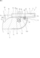
- FIG. 3 is a sectional view illustrating the oil seal and the second seal groove.
- FIG. 4 is a sectional view showing a modification of the oil seal.
- FIG. 5 is a sectional view of a conventional oil seal.
- the rolling bearing device of the present disclosure includes: A pestle-shaped roll, an axle box, an inner ring that rotates integrally with the pestle-shaped roll and has an inner ring raceway; an outer ring having an outer ring raceway facing the inner ring raceway and attached to the axle box; a plurality of rollers disposed between the inner ring raceway and the outer ring raceway; a labyrinth ring attached to the axle box so as to be radially opposed to an axial end of the inner ring; a packing attached to the inner ring and slidingly in contact with the labyrinth ring; an oil seal attached to the inner ring and slidingly in contact with the labyrinth ring; Equipped with The pestle-shaped roll has a small diameter shaft portion to which the inner ring is attached, and two large diameter portions having a larger diameter than the small diameter shaft portion, A first seal groove to which the packing is attached and a second seal groove to which the oil seal is attached are provided on the outer periphery of the inner
- the oil seal is a fixing part provided along the bottom surface of the groove; a lip portion that contacts the labyrinth ring; a biasing portion provided between the fixing portion and the lip portion;
- the biasing section is a first extending portion extending from the fixed portion to the outer side in the radial direction and the first side in the axial direction; a second extending portion extending from a relay portion that is a radially outer portion of the first extending portion to a second side in the radial direction and in the axial direction; All of the first extending portion and at least a portion of the second extending portion are provided between the first side surface and the second side surface, and the first extending portion is provided between the first side surface and the second side surface.
- the relay portion can come into contact with a side surface adjacent to the relay portion among the second side surface and the second side surface.
- the oil seal is interposed between the groove bottom surface and the labyrinth ring in a state of elastic compression deformation in the radial direction. Due to the elastic compression deformation and elastic restoring force of the biasing portion, the lip portion follows and contacts the labyrinth ring. Since each of the first extension part and the second extension part of the biasing part is elastically deformed, the oil seal as a whole tends to be elastically deformed in the radial direction, and the rigidity of the oil seal is reduced. As a result, even if the distance between the groove bottom surface and the inner circumferential surface of the labyrinth ring becomes narrow in a part of the circumferential direction, the lip portion is less likely to be crushed unevenly. Therefore, the lip portion can contact the labyrinth ring with a desired tightness.
- the relay part can contact the side surface of the second seal groove.
- the position of the biasing portion is regulated by the side surface, and the overall posture of the oil seal does not easily collapse.
- the lip portion can contact the labyrinth ring while maintaining the desired interference.
- a gap is provided between the relay part and a side surface adjacent to the relay part, and when the inner ring and the labyrinth ring move relative to each other in the axial direction, the relay part and the Contact with the sides.
- the axial width dimension of the first extending part is the same as or equal to the axial dimension of the second seal groove. If it is larger than , the biasing part may be constrained by the side surface. However, since the gap is provided, the biasing part is less likely to be restrained by the side surface, the lip part can easily follow the labyrinth ring, and the sealing performance does not deteriorate.
- the biasing part is a third part extending radially outward and to the first axial side from a second relay part that is a radially outer part of the second extension part. an extending portion, and the lip portion extends toward the labyrinth ring from a radially outer portion of the third extending portion. According to this configuration, the range in which the oil seal can be elastically deformed in the radial direction can be increased.
- FIG. 1 is a sectional view showing an example of a rolling bearing device 10.
- the rolling bearing device 10 is a device that includes a punch-shaped roll 3 and a bearing unit 19.
- the bearing unit 19 includes an inner ring 11, an outer ring 15, a plurality of cylindrical rollers (rolling elements) 13, a labyrinth ring 31, a packing 32, an oil seal 33, and an axle box 14.
- the bearing unit 19 supports the punch type roll 3.
- the punch-shaped roll 3 is used in a continuous casting machine.
- the punch-type roll 3 and another opposing punch-type roll sandwich and move the slab.
- the punch type roll 3 casts the moving slab while compressing it.
- the pestle-shaped roll 3 integrally includes a central small-diameter shaft portion 4 and two large-diameter portions 5, 5 provided on both sides of the small-diameter shaft portion 4 in the axial direction.
- the large diameter portion 5 has a larger diameter than the small diameter shaft portion 4.
- the pestle-shaped roll 3 has a small diameter shaft portion 4 supported by a bearing unit 19.
- the direction parallel to the central axis L1 is the axial direction of the rolling bearing device 10.
- a direction parallel to the central axis L1 is simply referred to as an "axial direction.”
- the direction perpendicular to the central axis L1 is the radial direction of the rolling bearing device 10.
- the direction perpendicular to the central axis L1 is simply referred to as the "radial direction.”
- the direction along the circle centered on the central axis L1 is the circumferential direction of the rolling bearing device 10.
- FIG. 1 is a sectional view taken in a plane including the central axis L1 and a vertical direction.
- the rolling bearing device 10 has a symmetrical configuration between a first axial side and a second axial side at the axial center of the small diameter shaft portion.
- the labyrinth ring 31, the packing 32, and the oil seal 33 are arranged on both sides of the rolling bearing device 10 in the axial direction.
- the labyrinth ring 31, packing 32, and oil seal 33 on the first axial side have the same configuration as those on the second axial side, and are arranged symmetrically.
- the axle box 14 has a two-part structure divided into upper and lower parts.
- the axle box 14 has a first axle box member 17 fixed to a common base plate of the casting machine segment, and a second axle box member 18 placed on the first axle box member 17.
- the first axle box member 17 and the second axle box member 18 are connected and fixed by bolts or the like not shown.
- the first axle box member 17 has a concave and spherical inner surface 17a on its upper surface side.
- the first axle box member 17 is an alignment ring.
- the outer ring 15 has a configuration in which an alignment outer ring is divided in half along a plane including its central axis.
- the inner peripheral surface of the outer ring 15 has a shape along a cylindrical surface centered on the central axis L1.
- the inner peripheral surface of the outer ring 15 has an outer ring raceway 15c.
- the outer ring 15 has a convex spherical outer diameter surface 15d.
- the spherical outer diameter surface 15d is able to abut and slide on the concave and spherical inner surface 17a.
- the second axle box member 18 is a member above the axle box 14.
- the inner peripheral surface of the second axle box member 18 has a shape along a cylindrical surface centered on the central axis L1.
- the inner peripheral surface of the second axle box member 18 has an outer ring raceway 18c.
- the inner ring 11 is attached to the small diameter shaft portion 4 by being fitted onto the outside of the small diameter shaft portion 4 .
- the inner ring 11 rotates together with the pestle-shaped roll 3.
- the inner ring 11 is a two-split bearing ring.
- the inner ring 11 has a first inner ring segment 11a and a second inner ring segment 11b each having a semi-cylindrical shape.
- the dividing surfaces of these inner ring division bodies 11a and 11b are on a plane containing the central axis of the inner ring 11.
- the inner ring segments 11a and 11b are connected and fixed by bolts or the like (not shown) to form an integral cylindrical member (inner ring 11).
- the inner ring 11 has a cylindrical inner ring raceway 11c on its outer peripheral side.
- the inner ring 11 has flanges 20, 20 having a larger diameter than the inner ring raceway 11c on both sides of the inner ring raceway 11c in the axial direction.
- the inner raceway 11c and the outer raceways 15c and 18c face each other in the radial direction.
- the rollers 13 are arranged between the inner ring raceway 11c and the outer ring raceways 15c and 18c. As the pestle-shaped roll 3 rotates together with the inner ring 11 relative to the outer ring 15 and the axle box 14, the rollers 13 roll on the inner ring raceway 11c and the outer ring raceways 15c, 18c.
- FIG. 2 is a sectional view showing a part of the first axial side of the rolling bearing device 10 shown in FIG. 1.
- the diameter of the outer peripheral surface 20a of the collar 20 of the inner ring 11 is larger than the diameter of the inner ring raceway 11c.
- a first seal groove 71 and a second seal groove 72 are provided on the outer peripheral surface 20a of the collar 20.
- the first seal groove 71 and the second seal groove 72 are each annular grooves.
- the seal grooves 71 and 72 are recessed radially inward from the outer peripheral surface 20a.
- the first seal groove 71 is a groove for attaching the packing 32
- the second seal groove 72 is a groove for attaching the oil seal 33.
- the packing 32 and the oil seal 33 come into contact with the inner peripheral surface 31d of the labyrinth ring 31.
- the sealing performance of the packing 32, the oil seal 33, and the labyrinth ring 31 prevents cooling water and casting scale from entering from the outside of the rolling bearing device 10 into the bearing interior 16 where the plurality of rollers 10 are present.
- the oil seal 33 also has the function of preventing lubricant such as grease or oil/air oil inside the bearing 16 from leaking to the outside.
- FIG. 3 is a cross-sectional view illustrating the oil seal 33 and the second seal groove 72.
- the second seal groove 72 includes a first side surface 76 that is annular, a second side surface 77 that is annular and axially opposed to the first side surface 76, and a first side surface 76 and a second side surface 77. and a groove bottom surface 78 provided between the groove bottom surface 78 and the groove bottom surface 78.
- the first side surface 76 is an annular plane extending radially inward from a portion of the outer circumferential surface 20a of the inner ring 11.
- the second side surface 77 is an annular plane extending radially inward from the other portion of the outer circumferential surface 20a of the inner ring 11.
- the groove bottom surface 78 is a cylindrical surface that extends in the axial direction from the radially inner end of the first side surface 76 and is connected to the radially inner end of the second side surface 77 .
- the groove bottom surface 78 is a cylindrical surface centered on the central axis of the inner ring 11 .
- the groove bottom surface 78 may be a conical surface or a part of a torus other than the above-mentioned cylindrical surface.
- the labyrinth ring 31 (see FIG. 1) is a generally cylindrical member.
- the labyrinth ring 31 is divided into two parts in the circumferential direction.
- the labyrinth ring 31 has a first semi-cylindrical portion 31a and a second semi-cylindrical portion 31b.
- the dividing planes of these half-cylindrical parts 31a and 31b lie on a plane that includes the central axis of the labyrinth ring 31.
- the central axis of the labyrinth ring 31 coincides with the central axis of the outer ring 15.
- a first half-cylindrical portion 31a constituting the lower half of the labyrinth ring 31 is attached to the first axle box member 17.
- the second half-cylindrical portion 31b constituting the upper half of the labyrinth ring 31 is attached to the second axle box member 18.
- the labyrinth ring 31 faces the axial end (flange 20) of the inner ring 11 in the radial direction.
- the labyrinth ring 31 on the first axial side (the right side in FIG. 1) is provided to protrude from the axle box 14 toward the first axial side.
- a portion 31c of the labyrinth ring 31 enters the concave circumferential groove 6 formed in the large diameter portion 5 of the punch-shaped roll 3.
- the labyrinth ring 31 on the second axial side (the left side in FIG. 1) is provided to protrude from the axle box 14 toward the second axial side.
- a portion 31c of the labyrinth ring 31 enters the concave circumferential groove 6 formed in the large diameter portion 5 of the punch-shaped roll 3.
- a labyrinth gap is formed between a portion 31c of the labyrinth ring 31 and the concave circumferential groove 6 on both sides in the axial direction.
- the labyrinth gap prevents foreign matter such as cooling water from entering the bearing interior 16 from the outside.
- the packing 32 As shown in FIG. 2, the packing 32 is fitted and attached to the first seal groove 71.
- the packing 32 includes a cylindrical portion 40 that slides into contact with the labyrinth ring 31, and a biasing portion 41 provided on the radially inner side of the cylindrical portion 40.
- the entire packing 32 including the cylindrical portion 40 may be made of rubber, the cylindrical portion 40 is made of resin in order to reduce the contact resistance with the labyrinth ring 31.
- the packing 32 is separated at one location in the circumferential direction.
- the packing 32 has a ring shape as a whole when attached to the inner ring 11. Since the packing 32 is separated at one point in the circumferential direction, it can be attached to the inner ring 11 having a smaller diameter than the large diameter portion 5 of the punch-shaped roll 3. When the pestle-shaped roll 3 and the inner ring 11 rotate, the packing 32 rotates together with the inner ring 11.
- the cylindrical portion 40 slides into contact with the inner circumferential surface 31d of the labyrinth ring 31.
- Oil seal 33 The oil seal 33 is fitted into the second seal groove 72 and attached.
- the oil seal 33 has a ring shape as a whole when attached to the inner ring 11. Since the oil seal 33 is separated at one location in the circumferential direction, it can be attached to the inner ring 11 having a smaller diameter than the large diameter portion 5 of the punch-shaped roll 3. When the pestle-shaped roll 3 and the inner ring 11 rotate, the oil seal 33 rotates together with the inner ring 11. The lip portions 53 and 54 of the oil seal 33 slide into contact with the inner peripheral surface 31d of the labyrinth ring 31.
- the oil seal 33 has a fixing part 51, a biasing part 52, a first lip part 53, and a second lip part 54.
- the first lip part 53 and the second lip part 54 will be collectively referred to as "lip part 55.”
- the fixing portion 51 is provided along the groove bottom surface 78.
- the lip portion 55 contacts the inner peripheral surface 31d of the labyrinth ring 31.
- the biasing portion 52 is provided between the fixed portion 51 and the lip portion 55.
- the fixing part 51, the biasing part 52, the first lip part 53, and the second lip part 54 are made of rubber and are elastically deformable.
- the fixed part 51 has a cylindrical shape.
- the fixing portion 51 has a protrusion 56 that protrudes radially inward from its inner peripheral surface.
- the protrusions 56 are provided at a plurality of locations in the circumferential direction.
- a hole 57 into which the protrusion 56 is inserted is provided in the groove bottom surface 78.
- the biasing part 52 has a first extending part 61 and a second extending part 62.
- the biasing portion 52 further includes a third extending portion 63 .
- the first extending portion 61 is a portion extending from the fixed portion 51 to the outside in the radial direction and to the first side in the axial direction (right side in FIG. 3).
- the first extending portion 61 extends from a portion including the end portion 51a on the second axial side (the left side in FIG. 3) of the fixed portion 51.
- a gap e1 is formed between the first relay portion 64, which is the radially outer portion of the first extending portion 61, and the end portion 51b on the first axial side (the right side in FIG. 3) of the fixed portion 51. radially provided between.
- the second extending portion 62 is a portion extending from the first relay portion 64 to the outside in the radial direction and to the second side in the axial direction (left side in FIG. 3).
- a gap e2 is formed between the second relay portion 65, which is the radially outer portion of the second extending portion 62, and the second axial side (the left side in FIG. 3) of the first extending portion 61. It is provided in the radial direction between the end portion 61a and the end portion 61a.
- the third extending portion 63 is a portion of the second extending portion 62 that extends from the second relay portion 65 to the outside in the radial direction and to the first side in the axial direction (right side in FIG. 3).
- a gap e3 is formed between the third relay portion 66, which is the radially outer portion of the third extending portion 63, and the first side in the axial direction (the right side in FIG. 3) of the second extending portion 62. It is provided in the radial direction between the end portion 62a and the end portion 62a.
- the lip portion 55 extends from the third relay portion 66 of the third extension portion 63 toward the labyrinth ring 31 .
- the first lip portion 53 extends from the third relay portion 66 toward the outside in the radial direction and the second side in the axial direction (left side in FIG. 3).
- the second lip portion 54 extends from the third relay portion 66 toward the outer side in the radial direction and the first side in the axial direction (the right side in FIG. 3).
- the entire first extending portion 61 and the entire second extending portion 62 are arranged between the first side surface 76 and the second side surface 77. That is, all of the first extending portion 61 and all of the second extending portion 62 are arranged within the range of the second seal groove 72.
- the first relay portion 64 is capable of contacting the adjacent first side surface 76 .
- a gap E1 is provided between the first relay portion 64 and the first side surface 76.
- the entire third extending portion 63 is disposed between the first side surface 76 and the second side surface 77. That is, the entire third extending portion 63 is disposed within the range of the second seal groove 72.
- the second relay portion 65 is capable of contacting the adjacent second side surface 77 .
- a gap E2 is provided between the second relay section 65 and the second side surface 77.
- the third relay portion 66 is capable of contacting the adjacent first side surface 76 .
- a gap E3 is provided between the third relay portion 66 and the first side surface 76.
- the side surface 64s of the first relay section 64, the side surface 65s of the second relay section 65, and the side surface 66s of the third relay section 66 are connected to the adjacent side surface (first side surface) of the second seal groove 72. It has a planar shape that is parallel to the side surface 76 or the second side surface 77).
- Each of the relay portions 64, 65, and 66 of the oil seal 33 can make surface contact with a side surface (first side surface 76 or second side surface 77) of the second seal groove 72.
- all of the third extending portion 63 is disposed between the first side surface 76 and the second side surface 77, while a portion of the third extending portion 63 is It may be arranged between the first side surface 76 and the second side surface 77. Furthermore, the entire third extension portion 63 may be arranged outside the second seal groove 72. In this case, at least a portion of the second extending portion 62 may be disposed between the first side surface 76 and the second side surface 77.
- FIG. 4 is a sectional view showing a modification of the oil seal 33.
- the second seal groove 72 is the same as the second seal groove 72 of the form shown in FIG.
- the oil seal 33 shown in FIG. 4 has a fixing part 51, a biasing part 52, a first lip part 53, and a second lip part 54, like the oil seal 33 in the form shown in FIG.
- the fixing portion 51 is provided along the groove bottom surface 78.
- the lip portion 55 contacts the inner peripheral surface 31d of the labyrinth ring 31.
- the biasing portion 52 is provided between the fixed portion 51 and the lip portion 55.
- the fixed part 51 has a cylindrical shape.
- the oil seal 33 shown in FIG. 4 has a ring-shaped spring 70 that presses the fixing portion 51 against the groove bottom surface 78.
- the oil seal 33 shown in FIG. 4 differs from the oil seal 33 shown in FIG. 3 in that it includes a spring 70.
- the spring 70 suppresses rotation of the oil seal 33 with respect to the inner ring 11. Note that, instead of the spring 70, a configuration including a protrusion 56 and a hole 57 shown in FIG. 3 may be adopted.
- the biasing section 52 in the form shown in FIG. 4 is different from the biasing section 52 in the form shown in FIG.
- the biasing section 52 in the form shown in FIG. 4 has a first extension part 61 and a second extension part 62, and It does not have the part 63.
- the urging portion 52 of the oil seal 33 shown in FIG. 4 will be explained. Note that the reference numerals of the structure of the oil seal 33 shown in FIG. 4, which have the same structure as the structure of the oil seal 33 shown in FIG. 3, are the same as the reference numerals of the structure of the oil seal 33 shown in FIG.
- the first extending portion 61 is a portion extending from the fixed portion 51 to the outside in the radial direction and to the first side in the axial direction (left side in FIG. 4).
- the first extending portion 61 extends from a portion including the end portion 51b on the second axial side (the right side in FIG. 4) of the fixed portion 51.
- a gap e1 is formed between the first relay portion 64, which is the radially outer portion of the first extending portion 61, and the end portion 51a on the first axial side (the left side in FIG. 4) of the fixed portion 51. radially provided between.
- the second extending portion 62 is a portion extending from the first relay portion 64 to the outside in the radial direction and to the second side in the axial direction (right side in FIG. 4).
- a gap e2 is formed between the second relay part 65, which is the radially outer part of the second extending part 62, and the second axial side (the right side in FIG. 4) of the first extending part 61. It is provided in the radial direction between the end portion 61a and the end portion 61a.
- the lip portion 55 extends from the second relay portion 65 of the second extension portion 62 toward the labyrinth ring 31 .
- the entire first extending portion 61 and the entire second extending portion 62 are arranged between the first side surface 76 and the second side surface 77. That is, all of the first extending portion 61 and all of the second extending portion 62 are arranged within the range of the second seal groove 72.
- the first relay portion 64 is capable of contacting the adjacent second side surface 77 .
- a gap E4 is provided between the first relay portion 64 and the second side surface 77.
- the second relay part 65 can come into contact with the adjacent first side surface 76.
- a gap E5 is provided between the second relay section 65 and the first side surface 76.
- all of the second extending portion 62 is disposed between the first side surface 76 and the second side surface 77, while a portion of the second extending portion 62 is It may be arranged between the first side surface 76 and the second side surface 77.
- the rolling bearing device 10 includes the oil seal 33 that is attached to the inner ring 11 and slides into contact with the labyrinth ring 31.
- Each type of oil seal 33 has a fixed part 51 provided along the groove bottom surface 78, a lip part 55 that contacts the labyrinth ring 31, and an attached part provided between the fixed part 51 and the lip part 55. It has a force part 52.
- the biasing portion 52 has a first extending portion 61 and a second extending portion 62.
- the first extending portion 61 extends from the fixed portion 51 to the outside in the radial direction and to the first side in the axial direction.
- the second extending portion 62 extends from the first relay portion 64, which is a radially outer portion of the first extending portion 61, to the radially outer side and the second side in the axial direction. All of the first extending portion 61 and at least a portion of the second extending portion 62 are provided between the first side surface 76 and the second side surface 77.
- the first relay section 64 can contact the side surface adjacent to the first relay section 64 between the first side surface 76 and the second side surface 77 .
- the oil seal 33 is interposed between the groove bottom surface 78 and the labyrinth ring 31 in a state of elastic compression deformation in the radial direction. Due to the elastic compression deformation and elastic restoring force of the biasing portion 41, the lip portion 55 follows and contacts the labyrinth ring 31. Since each of the first extending portion 61 and the second extending portion 62 of the biasing portion 41 is elastically deformed, the oil seal 33 as a whole is easily elastically deformed in the radial direction, and the rigidity of the oil seal 33 is as follows. descend. In other words, the flexibility of the oil seal 33 in the radial direction increases.
- the lip portion 55 can contact the labyrinth ring 31 with a desired interference.
- each of the first extending portion 61 and the second extending portion 62 is provided to extend in a straight line, and both , intersect at an acute angle.
- the third extending portion 63 is provided extending in a straight line, and the second extending portion 62 and the third extending portion 63 are , intersect at an acute angle.
- a conventional oil seal 99 shown in FIG. 5 has, in addition to a fixing part 97 and a lip part 98 made of rubber, two circular arc members 100 made of metal and embedded in the fixing part 97.
- the two arcuate members 100 are embedded in the fixed portion 97 apart from each other in the circumferential direction.
- the oil seal 33 shown in FIGS. 3 and 4 does not have the two circular arc members 100 made of metal embedded in the rubber portion. Therefore, the oil seal 33 is easily elastically deformed in the radial direction.
- the first relay portion 64 will not be able to move along the side surface of the second seal groove 72 (the first side surface 76 or the second side surface 76). side surface 77).
- the position of the biasing portion 52 is regulated by the side surface of the groove 71, so that the overall posture of the oil seal 33 does not easily collapse. Therefore, the lip portion 55 can contact the labyrinth ring 31 while maintaining the desired interference.
- the biasing portion 52 may be restrained by the side surface. In that case, the biasing portion 52 is flexibly and elastically deformed in the radial direction, making it difficult to cause the lip portion 55 to follow the labyrinth ring 31.
- a gap is provided between the first relay section 64 and the side surface adjacent to the first relay section 64.
- the first relay portion 64 comes into contact with the side surface.
- the biasing section 52 has a third extending section 63.
- the third extending portion 63 extends from the second relay portion 65, which is a radially outer portion of the second extending portion 62, toward the radially outer side and the first side in the axial direction. According to this configuration, the range in which the oil seal 33 can be elastically deformed in the radial direction can be increased.
- a gap may be provided between the fixing portion 51 of the oil seal 33 and the first side surface 76 and the second side surface 77 of the second seal groove 72. may be provided in contact with both the first side surface 76 and the second side surface 77 on both sides.
- the fixing portion 51 has a function of preventing the oil seal 33 from rotating.
- the form of the lip portion 55 can be changed and may be other than the form shown.
Landscapes
- Engineering & Computer Science (AREA)
- General Engineering & Computer Science (AREA)
- Mechanical Engineering (AREA)
- Sealing Using Fluids, Sealing Without Contact, And Removal Of Oil (AREA)
- Sealing Of Bearings (AREA)
Priority Applications (5)
| Application Number | Priority Date | Filing Date | Title |
|---|---|---|---|
| JP2024531843A JP7772216B2 (ja) | 2022-07-07 | 2022-07-07 | 転がり軸受装置 |
| DE112022007497.3T DE112022007497T5 (de) | 2022-07-07 | 2022-07-07 | Wälzlagervorrichtung |
| PCT/JP2022/026957 WO2024009453A1 (ja) | 2022-07-07 | 2022-07-07 | 転がり軸受装置 |
| CN202280096956.9A CN119546864A (zh) | 2022-07-07 | 2022-07-07 | 滚动轴承装置 |
| KR1020257000536A KR20250021544A (ko) | 2022-07-07 | 2022-07-07 | 구름 베어링 장치 |
Applications Claiming Priority (1)
| Application Number | Priority Date | Filing Date | Title |
|---|---|---|---|
| PCT/JP2022/026957 WO2024009453A1 (ja) | 2022-07-07 | 2022-07-07 | 転がり軸受装置 |
Publications (1)
| Publication Number | Publication Date |
|---|---|
| WO2024009453A1 true WO2024009453A1 (ja) | 2024-01-11 |
Family
ID=89453082
Family Applications (1)
| Application Number | Title | Priority Date | Filing Date |
|---|---|---|---|
| PCT/JP2022/026957 Ceased WO2024009453A1 (ja) | 2022-07-07 | 2022-07-07 | 転がり軸受装置 |
Country Status (5)
| Country | Link |
|---|---|
| JP (1) | JP7772216B2 (https=) |
| KR (1) | KR20250021544A (https=) |
| CN (1) | CN119546864A (https=) |
| DE (1) | DE112022007497T5 (https=) |
| WO (1) | WO2024009453A1 (https=) |
Citations (4)
| Publication number | Priority date | Publication date | Assignee | Title |
|---|---|---|---|---|
| JPS6319473A (ja) * | 1986-07-12 | 1988-01-27 | Koyo Shikagoroohaido Kk | 密封装置 |
| JPH0329767U (https=) * | 1989-08-01 | 1991-03-25 | ||
| JP2019060428A (ja) * | 2017-09-27 | 2019-04-18 | Ntn株式会社 | 転がり軸受装置およびそのシール部材 |
| DE102018119936A1 (de) * | 2018-08-16 | 2020-02-20 | Schaeffler Technologies AG & Co. KG | Pendelgleitlager |
Family Cites Families (2)
| Publication number | Priority date | Publication date | Assignee | Title |
|---|---|---|---|---|
| JP3029767U (ja) | 1996-03-21 | 1996-10-11 | 株式会社大成 | 包装用緩衝枠 |
| JP6710566B2 (ja) | 2016-04-14 | 2020-06-17 | 株式会社ジェイテクト | 軸受装置、組立体、及び密封装置 |
-
2022
- 2022-07-07 KR KR1020257000536A patent/KR20250021544A/ko active Pending
- 2022-07-07 DE DE112022007497.3T patent/DE112022007497T5/de active Pending
- 2022-07-07 CN CN202280096956.9A patent/CN119546864A/zh active Pending
- 2022-07-07 JP JP2024531843A patent/JP7772216B2/ja active Active
- 2022-07-07 WO PCT/JP2022/026957 patent/WO2024009453A1/ja not_active Ceased
Patent Citations (4)
| Publication number | Priority date | Publication date | Assignee | Title |
|---|---|---|---|---|
| JPS6319473A (ja) * | 1986-07-12 | 1988-01-27 | Koyo Shikagoroohaido Kk | 密封装置 |
| JPH0329767U (https=) * | 1989-08-01 | 1991-03-25 | ||
| JP2019060428A (ja) * | 2017-09-27 | 2019-04-18 | Ntn株式会社 | 転がり軸受装置およびそのシール部材 |
| DE102018119936A1 (de) * | 2018-08-16 | 2020-02-20 | Schaeffler Technologies AG & Co. KG | Pendelgleitlager |
Also Published As
| Publication number | Publication date |
|---|---|
| CN119546864A (zh) | 2025-02-28 |
| DE112022007497T5 (de) | 2025-05-08 |
| KR20250021544A (ko) | 2025-02-13 |
| JP7772216B2 (ja) | 2025-11-18 |
| JPWO2024009453A1 (https=) | 2024-01-11 |
Similar Documents
| Publication | Publication Date | Title |
|---|---|---|
| KR101483871B1 (ko) | 틸팅 인센서티브 씰 베어링 | |
| JP7151533B2 (ja) | ハブユニット軸受 | |
| JP2010190241A (ja) | 自動調心ころ軸受 | |
| CN107420434B (zh) | 轴承装置和密封装置 | |
| JP2013092206A (ja) | シール付車輪支持用軸受ユニット | |
| JP2012007664A (ja) | 分割型ニードル軸受及び軸受装置 | |
| US20130223782A1 (en) | Mechanical face seal assembly for bearings | |
| WO2024009453A1 (ja) | 転がり軸受装置 | |
| CN103573829B (zh) | 具有密封挡圈的轴承 | |
| JP2009074589A (ja) | 密封装置 | |
| WO2024009459A1 (ja) | 転がり軸受装置 | |
| JP6814897B2 (ja) | 軸受装置、密封装置、及び組立体 | |
| JP2023030822A (ja) | 転がり軸受及び転がり軸受ユニット | |
| JP5564180B2 (ja) | 密封装置、転がり軸受および車輪用転がり軸受 | |
| JP4893550B2 (ja) | 密封装置 | |
| JP2009024809A (ja) | 密封装置および転がり軸受装置 | |
| JP2009024804A (ja) | 密封装置 | |
| JP2019190608A (ja) | 密封装置 | |
| JP2009063117A (ja) | 転がり軸受 | |
| JP2014109370A (ja) | 軸受装置 | |
| JP2008075677A (ja) | 密封装置と密封装置を備えた車輪支持用ハブユニット | |
| WO2024127741A1 (ja) | 転がり軸受 | |
| JP2024154015A (ja) | 転がり軸受 | |
| JP2025167843A (ja) | 密封装置付き軸受 | |
| JP2024055678A (ja) | 密封装置 |
Legal Events
| Date | Code | Title | Description |
|---|---|---|---|
| 121 | Ep: the epo has been informed by wipo that ep was designated in this application |
Ref document number: 22950247 Country of ref document: EP Kind code of ref document: A1 |
|
| WWE | Wipo information: entry into national phase |
Ref document number: 2024531843 Country of ref document: JP |
|
| WWE | Wipo information: entry into national phase |
Ref document number: 202280096956.9 Country of ref document: CN |
|
| ENP | Entry into the national phase |
Ref document number: 20257000536 Country of ref document: KR Kind code of ref document: A |
|
| WWE | Wipo information: entry into national phase |
Ref document number: 1020257000536 Country of ref document: KR |
|
| WWE | Wipo information: entry into national phase |
Ref document number: 112022007497 Country of ref document: DE |
|
| WWP | Wipo information: published in national office |
Ref document number: 1020257000536 Country of ref document: KR |
|
| WWP | Wipo information: published in national office |
Ref document number: 202280096956.9 Country of ref document: CN |
|
| WWP | Wipo information: published in national office |
Ref document number: 112022007497 Country of ref document: DE |
|
| 122 | Ep: pct application non-entry in european phase |
Ref document number: 22950247 Country of ref document: EP Kind code of ref document: A1 |