WO2024004879A1 - 農業機械、農作業支援システム、農作業支援方法 - Google Patents
農業機械、農作業支援システム、農作業支援方法 Download PDFInfo
- Publication number
- WO2024004879A1 WO2024004879A1 PCT/JP2023/023406 JP2023023406W WO2024004879A1 WO 2024004879 A1 WO2024004879 A1 WO 2024004879A1 JP 2023023406 W JP2023023406 W JP 2023023406W WO 2024004879 A1 WO2024004879 A1 WO 2024004879A1
- Authority
- WO
- WIPO (PCT)
- Prior art keywords
- work
- traveling
- planting
- mechanisms
- ground work
- Prior art date
- Legal status (The legal status is an assumption and is not a legal conclusion. Google has not performed a legal analysis and makes no representation as to the accuracy of the status listed.)
- Ceased
Links
Images









Classifications
-
- A—HUMAN NECESSITIES
- A01—AGRICULTURE; FORESTRY; ANIMAL HUSBANDRY; HUNTING; TRAPPING; FISHING
- A01B—SOIL WORKING IN AGRICULTURE OR FORESTRY; PARTS, DETAILS, OR ACCESSORIES OF AGRICULTURAL MACHINES OR IMPLEMENTS, IN GENERAL
- A01B69/00—Steering of agricultural machines or implements; Guiding agricultural machines or implements on a desired track
- A01B69/007—Steering or guiding of agricultural vehicles, e.g. steering of the tractor to keep the plough in the furrow
- A01B69/008—Steering or guiding of agricultural vehicles, e.g. steering of the tractor to keep the plough in the furrow automatic
-
- A—HUMAN NECESSITIES
- A01—AGRICULTURE; FORESTRY; ANIMAL HUSBANDRY; HUNTING; TRAPPING; FISHING
- A01B—SOIL WORKING IN AGRICULTURE OR FORESTRY; PARTS, DETAILS, OR ACCESSORIES OF AGRICULTURAL MACHINES OR IMPLEMENTS, IN GENERAL
- A01B49/00—Combined machines
- A01B49/04—Combinations of soil-working tools with non-soil-working tools, e.g. planting tools
- A01B49/06—Combinations of soil-working tools with non-soil-working tools, e.g. planting tools for sowing or fertilising
-
- A—HUMAN NECESSITIES
- A01—AGRICULTURE; FORESTRY; ANIMAL HUSBANDRY; HUNTING; TRAPPING; FISHING
- A01B—SOIL WORKING IN AGRICULTURE OR FORESTRY; PARTS, DETAILS, OR ACCESSORIES OF AGRICULTURAL MACHINES OR IMPLEMENTS, IN GENERAL
- A01B59/00—Devices specially adapted for connection between animals or tractors and agricultural machines or implements
- A01B59/06—Devices specially adapted for connection between animals or tractors and agricultural machines or implements for machines mounted on tractors
-
- A—HUMAN NECESSITIES
- A01—AGRICULTURE; FORESTRY; ANIMAL HUSBANDRY; HUNTING; TRAPPING; FISHING
- A01B—SOIL WORKING IN AGRICULTURE OR FORESTRY; PARTS, DETAILS, OR ACCESSORIES OF AGRICULTURAL MACHINES OR IMPLEMENTS, IN GENERAL
- A01B69/00—Steering of agricultural machines or implements; Guiding agricultural machines or implements on a desired track
-
- A—HUMAN NECESSITIES
- A01—AGRICULTURE; FORESTRY; ANIMAL HUSBANDRY; HUNTING; TRAPPING; FISHING
- A01B—SOIL WORKING IN AGRICULTURE OR FORESTRY; PARTS, DETAILS, OR ACCESSORIES OF AGRICULTURAL MACHINES OR IMPLEMENTS, IN GENERAL
- A01B79/00—Methods for working soil
- A01B79/005—Precision agriculture
-
- A—HUMAN NECESSITIES
- A01—AGRICULTURE; FORESTRY; ANIMAL HUSBANDRY; HUNTING; TRAPPING; FISHING
- A01C—PLANTING; SOWING; FERTILISING
- A01C11/00—Transplanting machines
- A01C11/02—Transplanting machines for seedlings
Definitions
- the present invention relates to an agricultural machine that performs ground work using a working device installed on the traveling machine while traveling in a field, and a farm work support system and a farm work support method that support farm work by the agricultural machine.
- Patent Document 1 discloses an agricultural machine that performs ground work in a field.
- the agricultural machine disclosed in Patent Document 1 is composed of a rice transplanter, and includes a traveling machine that travels in a field, a work device that performs ground work that is installed at the rear of the traveling machine, a route setting unit, and a control that controls these. Equipped with equipment.
- the working device is composed of a seedling planting device, and has a plurality of (four) seedling planting mechanisms for planting paddy rice seedlings in the field.
- the control device plants seedlings in the field using planting arms provided in the plurality of seedling planting mechanisms while causing the traveling machine to travel along a target traveling route set in the field (paddy field) by the route setting unit.
- the control device disables each row clutch that passes through the already worked part of the field, and activates the seedling planting mechanism that passes through the already worked part. The system is stopped and the seedlings are planted by the planting arm of the seedling planting mechanism that passes through the unworked area.
- ground work mechanisms seedling planting mechanisms
- common there are cases where it is desired to form a part where ground work has been performed and a part where ground work has not been performed even in the center of the field.
- Conventional agricultural machinery and work equipment are not compatible with such irregular ground work, which is inconvenient.
- the present invention aims to improve the convenience when performing irregular ground work with agricultural machinery.
- the technical means of the present invention for solving the above technical problems is characterized by the following points.
- An agricultural machine includes a traveling body equipped with a work device having a plurality of ground work mechanisms that perform ground work, and a machine that indicates whether or not the ground work is to be performed in each of a plurality of areas of a field. and when the traveling body travels through the field and the work device passes through any one of the plurality of areas, the plurality of ground work mechanisms are acquired based on the work information. and a control device that operates each of the.
- the control device acquires the work information indicating whether or not each of the plurality of ground work mechanisms performs the ground work in each of the plurality of areas, and in the work information, determines whether or not each of the plurality of ground work mechanisms performs the ground work in each of the plurality of areas. If it is indicated that at least one of the plurality of ground work mechanisms does not perform ground work in any of the areas, when the work device passes through any of the areas, the ground work is not performed.
- the ground work mechanism that is indicated not to perform the ground work may not be operated, and the ground work mechanism that is indicated to perform the ground work may be operated.
- the control device determines a ground work mechanism that performs the ground work in each of the plurality of areas from among the plurality of ground work mechanisms based on the work information, and the control device determines which ground work mechanism performs the ground work in each of the plurality of areas, and the control device determines a ground work mechanism that performs the ground work in each of the plurality of areas.
- the ground work mechanism that has been determined to perform the ground work in the passing area may be operated.
- the agricultural machine includes a storage section for storing materials such as crop seeds or seedlings;
- the control device has a plurality of cropping mechanisms for planting the material stored in the field in the field, and the control device determines whether each of the plurality of cropping mechanisms cultivates the material in each of the plurality of areas. You may decide.
- the agricultural machine is provided with a plurality of clutches that are provided corresponding to each of the plurality of cropping mechanisms and can be switched between an engaged state and a disengaged state, and each of the plurality of cropping mechanisms is connected to a prime mover provided on the traveling machine body.
- the planting arm is configured to take out the seedling from the storage section and plant it in the field when a corresponding one of the plurality of clutches is in an engaged state, and the planting arm drives the seedling in the field.
- the control device disables the corresponding clutch when operating each of the plurality of planting mechanisms without taking out the seedling from the storage section or planting the seedling in the field when the clutch is in the disengaged state. When the clutch is switched to the engaged state and each of the plurality of cropping mechanisms is not operated, the corresponding clutch may be switched to the disengaged state.
- the agricultural machine includes a position detection device that detects the position of the traveling machine based on a satellite signal received from a satellite positioning system, and the control device detects the position of the traveling machine based on the position of the traveling machine detected by the position detecting device. Based on the information, it is determined which area the traveling aircraft has reached among the plurality of areas, and whether or not the ground work is to be performed in the area reached by the traveling aircraft among the work information.
- the ground working mechanism that performs the ground work in the area reached by the traveling aircraft may be determined among the plurality of ground working mechanisms by referring to the specific information shown.
- the plurality of ground working mechanisms are arranged side by side in the width direction of the traveling aircraft, and the control device determines which of the plurality of ground working mechanisms is selected based on the work information and the traveling direction of the traveling aircraft.
- a ground work mechanism that performs the ground work in each of a plurality of areas may be determined.
- the control device creates a travel route for the traveling machine to perform the ground work in the field based on the work information and the work width of the work device, and based on the work information and the travel route.
- a ground working mechanism that performs the ground work in each of the plurality of areas is determined, and while traveling the traveling aircraft along the traveling route, one of the ground working mechanisms is determined to perform the ground work in each of the plurality of areas.
- the ground work mechanism that has been determined to perform the ground work may be operated in any area through which the work device passes.
- the agricultural work support system of the present invention includes the agricultural machine and a support device that creates work information indicating whether or not ground work is to be performed in each of a plurality of areas of the field.
- the traveling body of the agricultural machine is equipped with a working device having a plurality of planting mechanisms for planting materials in the field, and the support device is configured to control the agricultural machinery for each type of material.
- the work information may be created indicating whether or not a plurality of planting mechanisms perform planting work of the material in each of the plurality of areas.
- the agricultural work support method of the present invention is a agricultural work support method in which ground work is performed in a field using a working device having a plurality of ground work mechanisms installed on a traveling body of an agricultural machine, and wherein the ground work is carried out in a plurality of areas of the field. a step in which a control device included in the agricultural machine acquires work information indicating whether or not work is to be performed in each of the plurality of areas; when passing through an area, the control device operates each of the plurality of ground work mechanisms based on the work information.
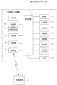
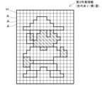
- FIG. 1 is a configuration diagram of an agricultural work support system. It is a side view of agricultural machinery (rice transplanter).
- FIG. 2 is a diagram showing the main parts of a seedling planting device of an agricultural machine. It is a figure showing the cooperation state of the clutch switching mechanism of agricultural machinery, and a clutch. It is a flowchart which shows an example of operation of agricultural machinery. It is a figure showing an example of work information. It is a diagram showing an example of a running route of agricultural machinery. It is a diagram showing an example of a seedling planting work state in a field. It is a flowchart which shows another example of operation of an agricultural machine. It is a diagram showing an example of art drawn on a field using agricultural machinery.
- FIG. 1 is a configuration diagram of an agricultural work support system 100 according to an embodiment of the present invention.
- the agricultural work support system 100 includes an agricultural machine 1 and a support device 2.
- Agricultural machinery 1 consists of a rice transplanter.
- the agricultural machine 1 is equipped with a working device 10.
- the working device 10 includes a seedling planting device for planting seedlings of gramineous crops in a field.
- the working device 10 has a plurality of mechanisms for planting seedlings (materials) in a field (paddy field), as will be described later.
- the agricultural machine 1 includes a control device 3, a storage device 4, a detection device 5, an operating device 7, a display device 8, a communication device 9, a prime mover 11, a traveling device 12, a braking device 13, a transmission device 14, a steering device 15, and a coupling device. 16, and a battery 17.
- the agricultural machine 1 also has a configuration other than these, which is included in a general rice transplanter, for example (not shown).
- the control device 3 is an ECU (electronic control unit) having a CPU, memory, etc., and is a controller that controls the operation of each part of the agricultural machine 1.
- the storage device 4 is composed of volatile memory and nonvolatile memory.
- Control data for the control device 3 to control the operation of each part of the agricultural machine 1 and the working device 10 is stored in the internal memory and storage device 4 of the control device 3 in a readable and writable manner.
- the control data includes specifications of the agricultural machine 1, specifications of the working device 10, and information for performing ground work (seedling planting work) with the working device 10.
- the detection device 5 includes a positioning device 6.
- the positioning device 6 is installed on the traveling body 21 (Fig. 2) of the agricultural machine 1, and receives satellite signals transmitted from satellite positioning systems (positioning satellites) such as D-GPS, GPS, GLONASS, Hokuto, Galileo, and Michibiki. (position of a positioning satellite, transmission time, correction information, etc.) and detects the current position (for example, latitude, longitude) based on the satellite signal. That is, the positioning device 6 constitutes a position detection device that detects the position of the traveling body 21 of the agricultural machine 1.
- the control device 3 calculates the position of the working device 10 based on the position of the traveling device 21 detected by the positioning device 6 and the relative position of the working device 10 with respect to the traveling device 21.
- the detection device 5 includes sensors (not shown) installed in each part of the agricultural machine 1 and the working device 10.
- the detection device 5 detects the operating state (drive and the state of stoppage, operating position, etc.). Further, the detection device 5 detects the operating state of the working device 10 and the power supply and power storage state of the battery 17 based on output signals from sensors and the like.
- the detection device 5 includes an object sensor composed of a laser sensor such as LiDAR, an ultrasonic sensor, a camera, or the like.
- the object sensors are installed at the front, rear, and left and right sides of the traveling body 21.
- the detection device 5 detects the presence or absence of an object around the agricultural machine 1 and the working device 10, the distance to the object, etc. from the output signal from the object sensor.
- the operating device 7 includes various operating members such as switches, keys, handles, levers, and pedals for operating the agricultural machine 1 and the working device 10, respectively, and a sensor that outputs a signal according to the operating state of each operating member. and electrical circuits.
- the display device 8 includes a touch panel and the like. Various information is displayed on the display device 8. Furthermore, by performing predetermined operations on the display screen of the display device 8, various information can be input.
- the operating device 7 and the display device 8 are input interfaces of the agricultural machine 1.
- the communication device 9 includes an antenna and an electric circuit for wirelessly communicating with the support device 2 via a public communication network such as the Internet.
- the support device 2 is a device that supports agricultural work by the agricultural machine 1.
- the support device 2 includes a terminal device (computer) provided outside the agricultural machine 1 and having a processor, such as a personal computer, a tablet machine, or a smartphone.
- the control device 3 communicates with the support device 2 through the communication device 9 and sends and receives information and data to and from the support device 2 .
- the communication device 9 is a communication interface of the agricultural machine 1 and an input interface.
- the prime mover 11 is composed of an engine.
- the prime mover 11 may be configured by, for example, an electric motor.
- the traveling device 12 includes wheels (front wheels 22F and rear wheels 22R in FIG. 2) that support the traveling body 21, a traveling mechanism that rotationally drives the wheels, an electromagnetic control valve and hydraulic equipment that operate the traveling mechanism, and the like. ing.
- a fuel injection device and the like for driving the prime mover 11 may also be included in the traveling device 12.
- the braking device 13 includes a brake, an electromagnetic control valve for operating the brake, hydraulic equipment, and the like.
- the control device 3 causes the traveling device 12 to cause the traveling body 21 to travel, and causes the braking device 13 to stop the traveling device 12 from traveling.
- the transmission 14 includes a transmission mechanism that transmits the power of the prime mover 11 to the traveling device 12, the working device 10, etc., a mechanism that switches the rotation direction of the wheels, a mechanism that switches the plurality of gears of the traveling machine body 21, and the like. ing. Further, the transmission 14 includes an electromagnetic control valve, hydraulic equipment, etc. that operate each of the mechanisms described above.
- the control device 3 transmits the power of the prime mover 11 to the traveling device 12, the working device 10, etc. through the transmission 14, and operates the traveling device 12, the working device 10, etc. Further, when the traveling body 21 is traveling, the control device 3 changes the gear position using the transmission 14, and changes the traveling direction of the traveling body 21 using the transmission 14 and the traveling device 12.
- the steering device 15 includes a steering mechanism that steers the traveling aircraft 21 (front wheels 22F), an electromagnetic control valve and hydraulic equipment that operate the steering mechanism, and the like.
- the steering device 15 also includes a power steering mechanism that assists in operating a steering handle 23 (FIG. 2) that manually operates the steering mechanism.
- the control device 3 steers the traveling body 21 using the steering device 15 when the traveling body 21 is traveling.
- the coupling device 16 includes a link mechanism 26 (FIG. 2) for coupling the traveling body 21 and the working device 10, and an electromagnetic control valve and hydraulic equipment for vertically swinging the link mechanism 26.
- the traveling body 21 and the working device 10 are connected via a connecting device 16.
- the control device 3 moves the working device 10 up and down using the coupling device 16.
- the battery 17 supplies power to various electrical components mounted on the agricultural machine 1.
- FIG. 2 is a side view of the agricultural machine (rice transplanter) 1.
- the left side is the front of the traveling body 21 of the agricultural machine 1
- the right side is the rear of the traveling body 21.
- the back side is the right side of the traveling body 21, and the near side is the left side of the traveling body 21.
- the traveling body 21 is supported by front wheels 22F and rear wheels 22R of the traveling device 12.
- a pair of front wheels 22F and a pair of rear wheels 22 are provided on each side.
- a prime mover 11 and a transmission 14 are mounted on the front part of the traveling body 21.
- a driver's seat 24 is installed in the upper center of the traveling body 21.
- a steering handle 23 In front of the driver's seat 24 and above the traveling body 21, a steering handle 23, an operating lever (numerical symbol omitted), and an operating panel 25 are installed.
- the operation panel 25 includes the aforementioned operation device 7, display device 8 (FIG. 1), and the like.
- a coupling device 16 is attached to the rear of the traveling body 21.
- the coupling device 16 includes a four-link type link mechanism 26 and a hydraulic cylinder 27.
- a base end portion of the link mechanism 26 is connected to the traveling body 21 so as to be able to swing up and down.
- a working device (seedling planting device) 10 is connected to the tip of the link mechanism 26 .
- the rod of the hydraulic cylinder 27 expands and contracts, the tip of the link mechanism 26 swings up and down, and the working device 10 moves up and down.
- the seedling stand 40 is a storage section for storing seedlings.
- the seedling stand 40 is supported by the frame (numerals omitted) of the working device 10, support rails 45, etc., and is inclined at a predetermined angle as shown in FIG.
- the seedling stand 40 has placing parts 40a to 40h on which a mat-like group of seedlings in which a plurality of seedlings are aggregated are placed so that they are lined up in the width direction (horizontal direction) of the traveling machine body 21. A plurality (eight) of them are formed.
- the lateral transport mechanism 41 is a mechanism that reciprocates a plurality of seedling groups placed on the placing parts 40a to 40h of the seedling table 40 in the width direction of the traveling body 21.
- the lateral feed mechanism 41 includes a helical shaft 47, a feeding member 48 attached to the helical shaft 47, and the like.
- the feeding member 48 and the seedling stand 40 are connected via a bracket 49.
- the helical shaft 47 is rotatably supported by the transmitter 50 and the support frame 46.
- the support frame 46 is connected to the case of the transmitter 50 in parallel to the width direction of the traveling body 21.
- the transmitter 50 is composed of a plurality of gears and a shaft supporting the gears, and transmits the power of the prime mover 11 transmitted via the PTO shaft 51 (FIG. 2) to each part of the working device 10.
- the feeding member 48 By rotating the helical shaft 47 by the power of the prime mover 11 transmitted by the transmitter 50, the feeding member 48 reciprocates in the width direction of the traveling body 21 along the helical shaft 47, and the seedling stand 40 is moved to the support rail 45. It reciprocates along the width direction of the traveling body 21. As a result, the group of seedlings placed on the placing parts 40a to 40h of the seedling stand 40 also reciprocate in the width direction of the traveling body 21.
- the seedling planting mechanism 42 is an example of a ground work mechanism that performs ground work in a field, and is also an example of a planting mechanism that plants seedlings in a field.
- a plurality of (four) seedling planting mechanisms 42 are provided so as to be lined up at predetermined intervals in the width direction of the traveling body 21.
- the plurality of seedling planting mechanisms 42 are arranged in order from the left side (right side in FIG. 3) of the traveling body 21, respectively: a first seedling planting mechanism 42a, a second seedling planting mechanism 42b, a third seedling planting mechanism 42c, It is sometimes referred to as a fourth seedling planting mechanism 42d.
- the seedling planting mechanism 42 (42a to 42d) includes a transmission case 52, a rotating body 53, a planting arm 54, and the like.
- a plurality of (four) transmission cases 52 are cantilever-like connected to the support frame 46 at predetermined intervals in the width direction of the traveling body 21.
- the power of the prime mover 11 is transmitted to each transmission case 52 via a transmitter 50 and a transmission shaft 56.
- Each transmission case 52 accommodates a chain, a sprocket (not shown), a planting clutch 55, and the like.
- a rotating body 53 is rotatably supported on the left and right sides of each transmission case 52.
- a planting arm 54 is rotatably supported at both ends of each rotating body 53. That is, each of the plurality of seedling planting mechanisms 42 is provided with two rotating bodies 53 and four planting arms 54. Further, eight rotating bodies 53 are provided so as to correspond one-to-one to the placing parts 40a to 40h of the seedling stand 40. Sixteen planting arms 54 are provided so as to correspond one to two to the placing parts 40a to 40h.
- the power of the prime mover 11 is transmitted to the rotating body 53 via the PTO shaft 51, the transmitter 50, the transmission shaft 56, the transmission case 52, the chain in the transmission case 52, and the planting clutch 55, and the rotating body 53 rotates. . Then, the two planting arms 54 supported by the rotating body 53 alternately take out a predetermined number of seedlings from the lower part of the group of seedlings placed on the corresponding placing parts 40a to 40h of the seedling stand 40. The seedlings are planted on the surface of a paddy field.
- a plurality of (four) planting clutches 55 are provided so as to correspond one-to-one with the seedling planting mechanism 42 and to correspond to two planting rows adjacent to each other.
- the plurality of planting clutches 55 are sequentially arranged from the left side (right side in FIG. 3) of the traveling body 21, respectively: a first planting clutch 55a, a second planting clutch 55b, a third planting clutch 55c, and a fourth planting clutch. It is sometimes referred to as a clutch 55d.
- Each planting clutch 55 (55a to 55d) can be switched between an engaged state and a disengaged state.
- the power of the prime mover 11 is transmitted to the rotating bodies 53 on both left and right sides of each clutch 55, and the rotating bodies 53 rotate.
- the planting arm 54 supported by the rotating body 53 takes out the seedlings from the corresponding placement parts 40a to 40h and plants the seedlings on the rice field.
- the power of the prime mover 11 is not transmitted to the rotating bodies 53 on both the left and right sides of each clutch 55, so the rotating bodies 53 do not rotate (stopped state).
- each planting clutch 55 is in an engaged state due to the elastic force of a spring (not shown).
- the vertical feeding mechanism 43 is a mechanism that feeds the seedling groups placed on the placement parts 40a to 40h of the seedling table 40 downward.
- a plurality of vertical feeding mechanisms 43 (four) are provided so as to correspond one-to-one with the seedling planting mechanism 42.
- the plurality of vertical feed mechanisms 43 are sequentially arranged from the left side (right side in FIG. 3) of the traveling body 21, respectively: a first vertical feed mechanism 43a, a second vertical feed mechanism 43b, a third vertical feed mechanism 43c, and a fourth vertical feed mechanism. It is sometimes referred to as mechanism 43d.
- First vertical feeding mechanism 43a and first seedling planting mechanism 42a, second vertical feeding mechanism 43b and second seedling planting mechanism 42b, third vertical feeding mechanism 43c and third seedling planting mechanism 42c, fourth vertical feeding mechanism 43d and the fourth seedling planting mechanism 42d correspond to each other.
- a pair of endless rotating belts 57 are installed on each of the mounting sections 40a to 40h.
- Each vertical feeding mechanism 43 (43a to 43d) includes four endless rotation belts 57 installed on two adjacent placement sections among the plurality of placement sections 40a to 40h, and four endless rotation belts 57 installed on two adjacent placement sections among the plurality of placement sections 40a to 40h.
- a transmission shaft 59 is connected to the drive shaft 58 of each vertical feed mechanism 43 via a feed clutch 60.
- each vertical feed mechanism 43 the power of the prime mover 11 is transmitted to the drive shaft 58 via the PTO shaft 51, the transmitter 50, the transmission shaft 59, and the feed clutch 60, and the drive shaft 58 rotates, thereby causing the drive shaft 58 to rotate.
- An endless rotating belt 57 attached to a shaft 58 rotates to send the seedling groups placed on the corresponding placement parts 40a to 40h downward.
- a plurality of feed clutches 60 (four) are provided so as to correspond one-to-one with the vertical feed mechanism 43 and to correspond to two planting rows adjacent to each other.
- the plurality of feed clutches 60 will be referred to as a first feed clutch 60a, a second feed clutch 60b, a third feed clutch 60c, and a fourth feed clutch 60d, respectively, from the left side of the traveling body 21 (right side in FIG. 3).
- the first feed clutch 60a and the first vertical feed mechanism 43a, the second feed clutch 60b and the second vertical feed mechanism 43b, the third feed clutch 60c and the third vertical feed mechanism 43c, the fourth feed clutch 60d and the fourth vertical feed mechanism 43d correspond to each other.
- Each feed clutch 60 (60a to 60d) can be switched between an engaged state and a disengaged state.
- the power of the prime mover 11 is transmitted to the drive shaft 58 connected to each feed clutch 60, and the drive shaft 58 rotates.
- the endless rotation belt 57 attached to the drive shaft 58 rotates, and the seedling groups placed on the mounting sections 40a to 40h provided with the endless rotation belt 57 rotate. is sent downward.
- the feed clutch 60 is in the disengaged state, the power of the prime mover 11 is not transmitted to the drive shaft 58 connected to each feed clutch 60, and the drive shaft 58 does not rotate (stopped state).
- each feed clutch 60 is in an engaged state due to the elastic force of a spring (not shown).
- the plurality of planting clutches 55 and the plurality of feeding clutches 60 are switched between an engaged state and a disengaged state by the clutch switching mechanism 44.
- the clutch switching mechanism 44 includes an electric motor 61, a reduction mechanism 62, gears 63, 64, an operating shaft 65, a potentiometer 66, cams 67a to 67d, arms 68a to 68d, wires 69, 71, 72, and the like.
- the electric motor 61 and the speed reduction mechanism 62 are installed on the back side of the seedling stand 40 (the surface where the placing parts 40a to 40h are not provided) via a bracket (not shown).
- the operating shaft 65 is rotatably installed on the back side of the seedling stand 40 via a bracket (not shown).
- a gear 64 is connected to the right end of the operating shaft 65, and the gear 64 meshes with the gear 63.
- the speed reduction mechanism 62 is connected to a gear 63 and a rotating shaft of the electric motor 61.
- Cams 67a to 67d are attached to the operating shaft 65 at predetermined intervals. A plurality (four) of the cams 67a to 67d are provided so as to correspond one-to-one to the seedling planting mechanism 42 and the vertical feeding mechanism 43, respectively.
- the power of the electric motor 61 (rotational force of the rotating shaft) is transmitted to the operating shaft 65 via the reduction mechanism 62 and gears 63, 64, and the operating shaft 65 rotates, thereby rotating the cams 67a to 67d.
- Potentiometer 66 detects the rotation angle of operating shaft 65.
- FIG. 4 is a diagram schematically showing the cooperation state of the clutch switching mechanism 44, the planting clutch 55, and the feeding clutch 60.
- a first cam surface 67x and a second cam surface 67y are formed on the circumferential surface of each cam 67a to 67d.
- the distance from the center of each cam 67a to 67d to the second cam surface 67y is longer than the distance from the center of each cam 67a to 67d (the axis of the operating shaft 65) to the first cam surface 67x. .
- the plurality of cams 67a to 67d are attached to the operating shaft 65 so that the positions of the first cam surface 67x and the second cam surface 67y are shifted by a predetermined phase (rotation angle) when viewed from the axial direction of the operating shaft 65. It is being
- a plurality (four) of arms 68a to 68d are provided in one-to-one correspondence with the cams 67a to 67d.
- the base end portion of each arm 68a to 68d is supported by a bracket (not shown) via a support shaft 73.
- the bracket is fixed to the back surface of the seedling stand 40.
- a roller 74 is attached to the center of each arm 68a to 68d. Each roller 74 is in contact with the peripheral surface of the corresponding cam 67a to 67d.
- the upper end of a wire 69 is connected to the tip of each of the arms 68a to 68d.
- the lower end of each wire 69 is connected to a branch member 70, respectively.
- Two wires 71 and 72 extend from the branch member 70.
- the tip of the wire 71 is connected to the corresponding planting clutch 55 (55a to 55d), and the tip of the wire 72 is connected to the corresponding feed clutch 60 (60a to 60d).
- the rollers 74 of the plurality of arms 68a to 68d come into contact with the first cam surfaces 67x of the corresponding cams 67a to 67d, respectively.
- the plurality of arms 68a to 68d rotate around the support shaft 73 while contacting the two cam surfaces 67y.
- the roller 74 is in contact with the first cam surface 67x of the cams 67a to 67d, the arms 68a to 68d do not pull the connected wires 69, 71, and 72, and are connected to the corresponding planting clutch 55 (55a to 55d).
- the feed clutches 60 (60a to 60d) are in an engaged state due to the elastic force of a spring (not shown).
- a spring not shown
- the roller 74 rides on (contacts) the second cam surface 67y of the cams 67a to 67d
- the arms 68a to 68d pull the connected wires 69, 71, and 72, and engage the corresponding planting clutch 55 (55a to 55d).
- the feed clutches 60 (60a to 60d) are disengaged.
- the plurality of cams 67a to 67d are attached to the operating shaft 65 such that the positions of the first cam surface 67x and the second cam surface 67y are shifted by a predetermined phase, so that the operating shaft
- the state of cooperation between cams 67a to 67d, arms 68a to 68d, planting clutch 55, and feed clutch 60 changes into eight patterns. That is, in the state shown in FIG. 4, the rollers 74 of all the arms 68a to 68d are in contact with the first cam surfaces 67x of all the cams 67a to 67d, and all the planting clutches 55 (55a to 55d) and the feed clutch 60 (60a to 60d) are in the ON state.
- the roller 74 of the arm 68b also comes into contact with the second cam surface 67y of the cam 67b, and the second planting clutch 55b and the second feed
- the clutch 60b is also in the disengaged state
- the roller 74 of the arm 68c is also in contact with the second cam surface 67y of the cam 67c
- the third planting clutch 55c and the third feed clutch 60c are also in the disengaged state
- the roller 74 of the arm 68d is also in the disengaged state.
- the fourth planting clutch 55d and the fourth feed clutch 60d are also disengaged.
- rollers 74 of all the arms 68a to 68d are in contact with the second cam surfaces 67y of all the cams 67a to 67d, and all the planting clutches 55 (55a to 55d) and feed clutches 60 (60a to 60d) are connected to each other.
- the roller 74 of the arm 68a comes into contact with the first cam surface 67x of the cam 67a, and the first The attached clutch 55a and the first feed clutch 60a are in the engaged state.
- the roller 74 of the arm 68b comes into contact with the first cam surface 67x of the cam 67b, and the second planting clutch 55b and the second feed
- the clutch 60b is also in the engaged state
- the roller 74 of the arm 68c is also in contact with the first cam surface 67x of the cam 67c
- the third planting clutch 55c and the third feed clutch 60c are also in the engaged state
- the roller 74 of the arm 68d is also in the engaged state.
- the fourth planting clutch 55d and the fourth feed clutch 60d are also engaged.
- the control device 3 (FIG. 1) controls the drive of the electric motor 61 and changes the rotation angle of the operating shaft 65, thereby controlling the plurality of planting clutches 55a to 55d and the plurality of feed clutches 60a to 60d, respectively.
- the seedling planting mechanisms 42a to 42d and the vertical feeding mechanisms 43a to 43d are respectively switched to either the operating state or the stopped state by switching between the open state and the cut state.
- FIG. 5 is a flowchart showing an example of the operation of the agricultural machine 1.
- Each process in FIG. 5 is executed by the control device 3 according to a software program stored in the internal memory.
- the control device 3 acquires work information corresponding to a field on which ground work (seedling planting work) is to be performed (S1). Work information is created by the support device 2.
- the control device 3 determines the field including the current position of the traveling machine body 21 detected by the positioning device 6 as the field to be worked on, and transmits work information corresponding to the field to be worked from the support device 2 to the communication device 9. Acquire (receive).
- the control device 3 stores the acquired work information in an internal memory or a predetermined storage area of the storage device 4.
- the work information created by the support device 2 is temporarily stored in a server (not shown) provided outside the agricultural machine 1, and the control device 3 transfers the work information corresponding to the field to be worked to the server.
- the information may be acquired by the communication device 9 from.
- the work information created by the support device 2 is temporarily stored in the portable memory, and when the portable memory is connected to a connection port (not shown) included in the communication device 9, the control device 3 becomes the work target.
- the work information corresponding to the field may be obtained from the portable memory.
- the control device 3 may acquire a plurality of pieces of work information created by the support device 2 from a server or a portable memory in advance and store it in the storage device 4, and then transmit the information to the traveling aircraft 21 detected by the positioning device 6.
- the field including the current position of may be determined as the field to be worked on, and work information corresponding to the field to be worked on may be acquired (read) from the storage device 4.
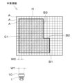
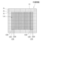
- FIG. 6 is a diagram embodying an example of work information.
- a field H having a rectangular outline is divided into a plurality of areas A. That is, each square grid shown inside the field H is the area A.
- the work information includes multiple areas A formed by dividing the field H into multiple areas, and information indicating whether seedling planting work (ground work) is to be performed in each of the multiple areas A. There is. More specifically, information indicating the positions (coordinates, etc.) of the plurality of areas A, and information indicating whether seedling planting work is to be performed by the plurality of seedling planting mechanisms 42a to 42d in each of the plurality of areas A are included. , included in the work information. Further, in order to indicate a plurality of areas A, information indicating the position (coordinates, etc.) of the field H and the contour H1 is also included in the work information.
- a hatched area C1 in the field H is the area where seedlings of a certain variety are planted using the work device (seedling planting device) 10.
- the work device seedling planting device 10.
- the multiple areas A included in the ground work portion C1 in the multiple areas A where the right boundary lines B1, B2, and B3 of the portion C1 intersect, at least one of the multiple seedling planting mechanisms 42a to 42d It is indicated that ground work will not be carried out.
- the above-mentioned work information is created by the support device 2 as described above.
- the operator sets the ground work portion C1 by operating an input interface such as an operation key provided on the support device 2 while looking at the outline of the field H displayed on a display provided on the support device 2.
- the CPU included in the support device 2 divides the field H into a plurality of areas A, associates each of the plurality of areas A with information indicating whether or not to perform seedling planting work, and creates work information. do.
- the CPU of the support device 2 also inputs information indicating that at least one of the seedling planting mechanisms 42a to 42d will not perform ground work in area A where the boundary line of the ground work portion C1 intersects. Include in information.
- the variety of seedlings to be planted in the ground work portion C1 may be set, and the set variety of seedlings may be included in the work information. Further, the width W2 of the area A may be set by operating the input interface of the support device 2.
- the control device 3 When the control device 3 acquires the work information (S1 in FIG. 5), the control device 3 controls the traveling machine 21 for performing ground work in the field H based on the work information and the work width W1 of the work device (seedling planting device) 10. A driving route Ls is created (S2). Note that, at this time, the control device 3 may also consider the external dimensions of the traveling machine body 21 and the working device (seedling planting device) 10 and create the traveling route Ls.
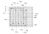
- FIG. 7 is a diagram showing an example of the traveling route Ls of the traveling body 21.
- the traveling route Ls shown in FIG. 7 is a virtual traveling route of the traveling machine 21 for performing ground work on the ground work portion C1 of the field H using the work device (seedling planting device) 10.
- the traveling route Ls includes a plurality of straight routes Ls (1) to L1 (9) along which the traveling aircraft 21 travels straight.
- the arrows of the plurality of straight routes Ls (1) to Ls (9) indicate the traveling direction of the traveling aircraft 21.
- the numbers 1 to 9 surrounded by circles on the plurality of straight routes Ls (1) to Ls (9) indicate the running order of the traveling aircraft 21.
- the base end of the arrow for the straight route Ls (1) is the start position Ps of the travel route Ls
- the tip of the arrow for the straight route Ls (9) is the end position Pg of the travel route Ls.
- the control device 3 After the worker operates the agricultural machine (rice transplanter) 1 to move the traveling machine body 21 to the starting position Ps of the travel route Ls in the field H, when the automatic operation switch included in the operating device 7 is turned on, the control is activated.
- the device 3 starts automatic operation of the agricultural machine (rice transplanter) 1 (S3 in FIG. 5). Note that automatic operation means that the control device 3 automatically runs the traveling machine 21 (adjusts the traveling speed) and steers it, and also automatically lifts and lowers the work device (seedling planting device) 10 and plants the seedlings. This is what you do.
- the positioning device 6 detects the position of the traveling aircraft 21 at a predetermined period (S4), and the link mechanism 26 (FIG. 2) detects the position of the traveling machine 21 (S4). 10 is lowered, and the traveling body 21 is made to travel along the traveling route Ls (S5). Furthermore, the control device 3 determines which area A of the plurality of areas A the traveling aircraft 21 has reached based on the position of the traveling aircraft 21 detected by the positioning device 6 (S6 ).
- control device 3 refers to the specific information indicating whether or not ground work is to be performed in the area A that the traveling aircraft 21 has reached (S7), among the work information, and controls the plurality of seedling planting mechanisms 42a to 42d. Among them, a seedling planting mechanism that performs the seedling planting work in area A that the traveling body 21 has reached is determined (S8). At this time, the control device 3 controls the area A that the traveling aircraft 21 has reached based on the above specific information and the position and traveling direction of the straight route Ls (1) to L1 (9) on which the traveling aircraft 21 is traveling. Determine the seedling planting mechanism that will carry out the seedling planting work.
- the control device 3 determines the traveling direction of the traveling aircraft 21 from the traveling direction of the straight routes Ls (1) to L1 (9) or from the change in the position of the traveling aircraft 21 detected by the positioning device 6.
- the control device 3 selects a seedling that has been decided to perform the seedling planting work in the area A from among the plurality of seedling planting mechanisms 42a to 42d.
- the planting mechanism is operated (S9).
- the traveling aircraft 21 when the traveling aircraft 21 travels along the straight route Ls (1) , the traveling aircraft 21 sequentially moves to a plurality of areas A on both left and right sides in the direction of travel of the straight route Ls (1).
- the specific information indicates that the seedling planting work will be carried out in all of the plurality of areas A. That is, the above specific information indicates that the seedling planting work is performed by all of the plurality of seedling planting mechanisms 42a to 42d. Therefore, the control device 3 causes all of the seedling planting mechanisms 42a to 42d to perform the seedling planting work in the area A that the traveling aircraft 21 has reached among the plurality of areas A on both the left and right sides of the straight route Ls (1). It is determined what to do (S8).
- the control device 3 causes the clutch switching mechanism 44 to turn on all the planting clutches 55 and the feed clutch 60, All the seedling planting mechanisms 42a to 42d are operated (S9), and when the working device (seedling planting device) 10 passes through the area A reached above, all the seedling planting mechanisms 42a to 42d plant the seedlings. do the work.
- the control device 3 When the traveling body 21 and the work device (seedling planting device) 10 reach the end point (tip of the arrow) of any of the straight routes Ls (1) to Ls (8) in FIG. , the control device 3 turns the traveling aircraft 21 toward the starting point (base end of the arrow) of the next straight route. At this time, the control device 3 raises the operating device (seedling planting device) 10 using the link mechanism 26, and prevents the plurality of seedling planting mechanisms 42a to 42d from performing seedling planting work. When the traveling body 21 reaches the starting point of the next straight route and the traveling direction of the traveling body 21 matches the traveling direction of the next straight route, the link mechanism 26 lowers the working device (seedling planting device) 10. Then, the traveling body 21 is caused to travel along the next straight route.
- the control device 3 controls the traveling aircraft It is decided that all the seedling planting mechanisms 42a to 42d will perform the seedling planting work in the area A reached by the robot 21 (S8 in FIG. 5), and the work device (seedling planting device) 10 passes through the area A. At the same time, all the seedling planting mechanisms 42a to 42d are operated (S9).
- the traveling aircraft 21 When the traveling aircraft 21 travels along the straight route Ls (5) , the traveling aircraft 21 sequentially reaches a plurality of areas A on both left and right sides in the traveling direction of the straight route Ls (5) .
- the work information indicates that seedling planting work will not be performed in the entire area A. .
- the specific information corresponding to the plurality of areas A indicates that the seedling planting work is not performed in the plurality of areas A as a whole. That is, the fact that the first seedling planting mechanism 42a and the second seedling planting mechanism 42b passing through the plurality of areas A do not perform the seedling planting work is specified in the work information corresponding to the plurality of areas A. shown in the information.
- the plurality of areas A located on the right side (left side in FIG. 7) in the traveling direction of the straight route Ls (5) from the starting point of the straight route Ls (5) to the switching position Pa, the plurality of areas A
- the work information indicates that seedling planting work is not performed in the left half of the area A (the right half in Figure 7), but seedling planting work is performed in the right half of the plurality of areas A (left half in Figure 7). indicated by the corresponding specific information.
- the third seedling planting mechanism 42c does not perform the seedling planting work, and the fourth seedling planting mechanism.
- the above specific information indicates that the seedling planting work is to be performed in 42d.
- the control device 3 determines whether the traveling aircraft 21 is In the reached area A, the fourth seedling planting mechanism 42d decides to perform the seedling planting work (S8 in FIG. 5), and the first to third seedling planting mechanisms 42a to 42c do not perform the seedling planting work. decide. Then, when the working device (seedling planting device) 10 also reaches the area A where the traveling body 21 has arrived, the control device 3 causes the clutch switching mechanism 44 to switch between the first to third planting clutches 55a to 55c and the first to third planting clutches 55a to 55c.
- the third feed clutches 60a to 60c are disengaged, the first to third seedling planting mechanisms 42a to 42c are not operated, and the fourth planting clutch 55d and the fourth feed clutch 60d are engaged to transfer the fourth seedling.
- the planting mechanism 42d is operated (S9). Thereby, when the working device (seedling planting device) 10 passes through the area A reached, only the fourth seedling planting mechanism 42d performs the seedling planting work.
- the traveling body 21 reaches the switching position Pa on the straight route Ls (5) , the traveling body 21 and the work device (seedling planting device) 10 move to the end point (tip of the arrow) of the straight route Ls (5).
- the control device 3 controls all the seedling planting mechanisms 42a to 42d to plant seedlings in the area A that the traveling body 21 has reached, similarly to when traveling along the straight route Ls (1) described above. It is decided to perform the planting work (S8 in FIG. 5). Then, the control device 3 operates all the seedling planting mechanisms 42a to 42d when the working device (seedling planting device) 10 passes through the area A reached above (S9).
- the traveling aircraft 21 travels along the straight route Ls (6) to L1 (9) , it travels to a plurality of areas A on both the left and right sides in the direction of travel of the straight route Ls (6) to L1 (9).
- the aircraft 21 arrive one after another.
- the work information that seedling planting work is not performed in the entire plurality of areas A. It is indicated by specific information corresponding to a plurality of areas A. That is, the above specific information indicates that the first seedling planting mechanism 42a and the second seedling planting mechanism 42b passing through the plurality of areas A do not perform seedling planting work.
- performing seedling planting work corresponds to the multiple areas A in the work information. Indicated by specific information. That is, the above specific information indicates that the third seedling planting mechanism 42c and the fourth seedling planting mechanism 42d that pass through the plurality of areas A perform the seedling planting work.
- the control device 3 controls the third seedling planting mechanism 42c and the fourth seedling planting mechanism in the area A that the traveling body 21 has reached among the plurality of areas A on the left and right sides of the straight route Ls (6 ) to L1 (9).
- the planting mechanism 42d decides to perform the seedling planting work (S8 in FIG. 5), and the first seedling planting mechanism 42a and the second seedling planting mechanism 42b decide not to perform the seedling planting work.
- the control device 3 causes the clutch switching mechanism 44 to switch between the first planting clutch 55a, the second planting clutch 55b, and the first planting clutch 55b.
- the feed clutch 60a and the second feed clutch 60b are disengaged, the first seedling planting mechanism 42a and the second seedling planting mechanism 42b are not operated, and the third planting clutch 55c, the fourth planting clutch 55d,
- the third feed clutch 60c and the fourth feed clutch 60d are turned on, and the third seedling planting mechanism 42c and the fourth seedling planting mechanism 42d are operated (S9).
- the working device (seedling planting device) 10 passes through the area A reached, the third seedling planting mechanism 42c and the fourth seedling planting mechanism 42d perform the seedling planting work.
- the control device 3 determines that the end condition is satisfied (S10: YES) and starts the agricultural machine (rice transplanter) 1. Automatic operation and work in field H are completed. As a result, as shown in FIG. 6, seedling planting work is performed on the ground work portion C1 of the field H by the agricultural machine (rice transplanter) 1 and the work device (seedling planting device) 10.
- the work of planting seedlings in portions C2 to C4 of the field H may be performed by the rice transplanter 1 and the seedling planting device 10, or may be performed manually.
- the support device 2 may create a plurality of pieces of work information corresponding to the respective sections C2 to C4. good.
- the control device 3 acquires the plural pieces of work information from the support device 2 or the like, and based on each piece of the plural pieces of work information, the control device 3 selects the agricultural machine (rice transplanter 1) and the work device (seedling planting machine). Seedlings corresponding to the respective portions C2 to C4 may be planted while automatically operating the attached device) 10.
- the control device 3 starts the automatic operation of the agricultural machine (rice transplanter 1) 1
- the control device 3 starts the automatic operation of the agricultural machine (rice transplanter 1), and then controls each of the plurality of areas A of the field H among the plurality of seedling planting mechanisms 42a to 42d.
- a seedling planting mechanism that performs the seedling planting work is determined, the present invention is not limited to this.
- the control device 3 creates work information, the driving route Ls, etc. after creating the driving route Ls (S2) and before starting automatic driving based on the driving route Ls (S3). Based on this, among the plurality of seedling planting mechanisms 42a to 42d, a seedling planting mechanism that performs the seedling planting work in each of the plurality of areas A of the field H and a seedling planting mechanism that does not perform the seedling planting work are selected.
- the determined result may be stored in the storage device 4 as work control information (S11).
- the control device 3 refers to the specific control information corresponding to the area A that the traveling aircraft 21 has reached, out of the work control information (S12), and determines the area A that the traveling aircraft 21 has reached.
- the seedling planting mechanism that has decided to perform the seedling planting work in area A may be operated when the work device (seedling planting device) 10 reaches the area A (S9).
- the support device 2 may create a travel route Ls for the traveling aircraft 21 and include the travel route Ls in the work information. Further, the support device 2 selects a plurality of areas A of the field H among the plurality of seedling planting mechanisms 42a to 42d based on the travel route Ls and the arrangement position (line up) of the plurality of seedling planting mechanisms 42a to 42d.
- the seedling planting mechanism that performs the ground work (seedling planting work) (and/or the seedling planting mechanism that does not perform the ground work) may be determined for each of the above, and the determined result may be included in the work information.
- the control device 3 controls the work information corresponding to the area A in which the traveling machine 21 travels.
- the seedling planting mechanism when the control device 3 automatically operates the agricultural machine (rice transplanter) 1, the seedling planting mechanism performs the seedling planting work in each of the plurality of areas A of the field H based on the work information.
- the present invention is not limited to this.
- an automatic system in which a worker operates the traveling speed of the traveling body 21 using an accelerator member, a brake member, a speed change switching member, etc. included in the operating device 7, and the control device 3 controls the steering of the traveling body 21, is also possible.
- the control device 3 controls the field position based on the work information.
- a seedling planting mechanism that performs seedling planting work in each of the plurality of areas A of H may be determined, and the determined seedling planting device may be operated.
- the travel route Ls may not be created, and the operator may run the travel body 21 along an arbitrary route.
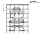
- FIG. 10 is a diagram showing an example of art drawn by performing seedling planting work using the agricultural machine (rice transplanter) 1 in the field H.
- the image is imported into the support device 2, superimposed on the field H displayed on the display of the support device 2, and the size of the image is adjusted. Then, using the input interface of the support device 2, the operator sets (inputs) the variety of seedlings used to represent each part of the image displayed on the display.
- the CPU of the support device 2 creates work information for each set type of seedling. For example, if the art image shown in FIG. 10 is expressed in four colors, the operator sets four types of grass seedlings with different leaf colors, so the CPU of the support device 2 Create four pieces of work information as shown. 11A to 11D are diagrams embodying an example of the first to fourth work information for each variety of seedling for drawing the art of FIG. 10 on the field H.
- the CPU of the support device 2 separates the image shown in FIG. 10 into different colors as shown in FIGS. 11A to 11D, and divides the field H containing each of the separated images into a plurality of areas A. Then, the CPU of the support device 2 determines whether or not to perform seedling planting work in each of the plurality of areas A based on the color information of each of the plurality of areas A shown in FIGS. 11A to 11D, and The determined information is associated with each of the plurality of areas A, and first to fourth work information including the plurality of areas A and the determined information are respectively created.
- the first work information shown in FIG. 11A indicates that ancient rice ⁇ seedlings with reddish-brown leaves are to be planted in the hatched area of field H, and the seedlings should not be planted in other areas. It is shown.
- the second work information shown in FIG. 11B indicates that ancient rice ⁇ seedlings with black leaves are to be planted in the hatched area of field H, and that the seedlings are not planted in other areas. It is shown.
- the third work information shown in FIG. 11C indicates that ancient rice ⁇ seedlings with yellow leaves are to be planted in the hatched area of field H, and that the seedlings are not planted in other areas. It is shown.
- the fourth work information shown in FIG. 11D indicates that paddy rice seedlings with green leaves are to be planted in the hatched area of the field H, and that the seedlings are not planted in other areas. ing.
- the control device 3 of the agricultural machine (rice transplanter) 1 acquires a plurality of pieces of work information (first to fourth work information) shown in FIGS. 11A to 11D in the procedure shown in FIG. 5 or 9, respectively, and Based on each of the plurality of pieces of work information, the seedling planting device 10 performs planting work of four types of seedlings in the field H. That is, each process shown in FIG. 5 or FIG. 9 is repeatedly executed by the control device 3 for each piece of work information (for each type of seedling).
- information indicating that seedlings of the corresponding variety are to be placed on the seedling stand 40 may be displayed on the display device 8 after the process S1 in FIG. 5 or 9 is executed and before the process S3 is executed. good.
- a common running route Ls may be created for a plurality of pieces of work information, or different running routes Ls may be created.
- control device 3 After the control device 3 performs seedling planting work in the field H using the seedling planting device 10 based on each of the plurality of work information shown in FIGS. 11A to 11D in the procedure shown in FIG. 5 or FIG. 9, As the planted seedlings grow, art is drawn on the field H as shown in FIG. 10. Traditionally, when creating art by planting paddy rice or ancient rice seedlings in a field (paddy field), the drafting of the image that would become the basis of the art and the work of planting the seedlings were done manually. Since the machine 1 can perform seedling planting work and draw art, it becomes possible to reduce the manual work burden.
- a plurality of planting clutches 55 (55a to 55d) (and feed clutches 60 (60a to 60d)) were turned on and off using the power of a single electric motor 61. It is not limited to.
- a plurality of actuators such as electric motors or electromagnetic solenoids are provided in the working device 10, and the control device 3 controls the operation of each of the plurality of actuators, so that the corresponding one or more actuators are controlled by the power of each of the plurality of actuators.
- the planting clutch 55 (and the feeding clutch 60) may be turned on and off.
- a plurality of actuators may be provided in a one-to-one correspondence with the plurality of planting clutches 55, or a plurality of actuators may be provided in a two-to-one correspondence with the plurality of planting clutches 55. It's okay.
- a plurality of planting clutches 55 may be irregularly connected, such as turning one planting clutch 55 on and off with one actuator, and turning on and off another one or more planting clutches 55 with one or more actuators.
- a corresponding plurality of actuators may be provided. (The same applies to the plurality of feed clutches 60.) As shown in FIG.
- the information may be configured to be transmitted.
- FIG. 12 is a diagram showing another state of cooperation between the clutch switching mechanism 44 and the clutches 55 and 60. According to the configuration shown in FIG. 12, for example, two types of seedlings that cannot be planted at the same time due to different growth periods are planted in the field H based on the work information shown in FIG. The planting rows can be arranged alternately.
- a plurality of (two) planting clutches 55a, 55c corresponding to a plurality (two) of odd-numbered seedling planting mechanisms 42a, 42c from the left side of the traveling body 21, and a plurality of even-numbered (two) seedling planting mechanisms 42a, 42c.
- a plurality of (two) actuators are provided so as to correspond to a plurality of (two) planting clutches 55b, 55d corresponding to the seedling planting mechanisms 42b, 42d, as shown in FIG. Planting rows of multiple types of seedlings can be arranged alternately.
- FIG. 13 is a diagram showing another example of work information.
- FIG. 14A is a diagram showing an example of the state of planting the first seedlings and the travel route Ls in FIG. 13.
- FIG. 14B is a diagram showing an example of the state of planting the second seedlings and the running route Ls in FIG. 13.
- the control device 3 of the agricultural machine 1 After acquiring work information as shown in FIG. 13, the control device 3 of the agricultural machine 1 creates a traveling route Ls as shown in FIGS. 14A and 14B. Then, the control device 3 first plants the first seedlings in the portion C5 of the field H based on the work information, the traveling route Ls, and the like.
- FIG. 14A and FIG. 13
- the locations where the first seedlings were planted are indicated by diagonal hatching.
- the control device 3 disconnects the second planting clutch 55b and the fourth planting clutch 55d using the actuators 75b and 75d when the traveling machine body 21 travels along the odd-numbered traveling route Ls. state, the actuators 75a and 75c turn the first planting clutch 55a and the third planting clutch 55c into the engaged state, and the first seedling planting mechanism 42a and the third seedling planting mechanism 42c move the first seedling to the field H. Plant one seedling.
- the control device 3 disables the first planting clutch 55a and the third planting clutch 55c by the actuators 75a and 75c, and disables the actuators 75a and 75c.
- 75b and 75d turn on the second planting clutch 55b and the fourth planting clutch 55d, and the second seedling planting mechanism 42b and the fourth seedling planting mechanism 42d plant the first seedlings in the field H. To go.
- control device 3 plants second seedlings that grow slower than the first seedlings in part C6 of the field H based on the work information, the travel route Ls, etc.
- FIG. 14B and FIG. 13
- the locations where the second seedlings were planted are indicated by dotted hatching.
- the control device 3 disconnects the first planting clutch 55a and the third planting clutch 55c using the actuators 75a and 75c when the traveling machine body 21 travels along the odd-numbered traveling route Ls. state, the actuators 75b and 75d turn on the second planting clutch 55b and the fourth planting clutch 55d, and the second seedling planting mechanism 42b and the fourth seedling planting mechanism 42d move the second seedling to the field H. Plant one seedling.
- the control device 3 disables the second planting clutch 55b and the fourth planting clutch 55d using the actuators 75b and 75d, and disables the second planting clutch 55b and the fourth planting clutch 55d.
- the first planting clutch 55a and the third planting clutch 55c are turned on, and the first seedling planting mechanism 42a and the third seedling planting mechanism 42c plant the first seedling in the field H. To go.
- the irregular seedling planting work shown in FIGS. 13 to 14B is also effective when applied to a transplanter for planting vegetable seedlings in fields, for example.
- a plurality of ground working mechanisms (seedling planting mechanisms) 42 (42a to 42d) are operated or stopped, respectively, and seedlings are planted between rows of seedlings planted in rows.
- a non-ground work area may be provided where no seeds are planted.
- the number of installed ground working mechanisms (seedling planting mechanisms) 42 (42a to 42d) in the working device (seedling planting device) 10 is not limited to the number of installations (four) shown in the above embodiment, It can be set as appropriate depending on the size or horsepower of the agricultural machine (rice transplanter) 1 and the working device 10. The same applies to the other mechanisms of the working device 10, the planting arm, and the actuator.
- the operating device 7 may be provided with a plurality of clutch switches that respectively turn on and off the plurality of planting clutches 55 and the like (also the feed clutch 76). Then, when the worker operates each of the plurality of clutch switches while referring to the work information displayed on the display device 8, the control device 3 selects the corresponding planting clutch according to the operation of the clutch switch. 55 etc. may be turned on and off to operate or stop the corresponding seedling planting mechanisms 42a to 42d.
- FIG. 15 is a diagram showing another example of planting materials in a field using the agricultural machine 1.
- FIG. 15 shows a state in which different materials (seedlings) are planted in every three rows in the field H.
- each row may be planted with one row or multiple rows of each seedling. Further, different materials may be planted in the field H by the agricultural machine 1 in four or more rows at intervals.
- the agricultural machine 1 and the agricultural work support system 100 of this embodiment described above have the following configurations and are effective.
- the agricultural machine 1 of the present embodiment includes a traveling body 21 equipped with a work device 10 having a plurality of ground work mechanisms 42 (42a to 42d) that perform ground work, and a traveling machine 21 that performs ground work in each of a plurality of areas A of a field H.
- a traveling machine body 21 travels in the field H and the work device 10 passes through any one of the plurality of areas A, the work information indicating whether or not to perform the work is acquired. and a control device 3 that operates each of the plurality of ground working mechanisms 42 (42a to 42d).
- the agricultural work support system 100 of this embodiment includes an agricultural machine 1 and a support device 2 that creates work information indicating whether or not ground work is to be performed in each of the plurality of areas A of the field H.
- the ground work method of the present invention is a ground work method in which ground work is performed in a field using a work device 10 having a plurality of ground work mechanisms 42 (42a to 42d) equipped on a traveling body 21 of an agricultural machine 1.
- the control device 3 operates each of the plurality of ground work mechanisms 42 (42a to 42d) based on the work information. We are prepared.
- the plurality of ground work mechanisms 42 (42a to 42d) equipped on the agricultural machine 1 can be operated individually based on work information, and can be used as a part that performs ground work in the field H for various purposes. It is possible to improve convenience when performing irregular ground work in which a portion where ground work is not performed is intentionally formed.
- the control device 3 acquires work information indicating whether each of the plurality of ground work mechanisms 42 (42a to 42d) performs ground work in each of the plurality of areas A, and acquires the work information. , if it is indicated that at least one of the plurality of ground work mechanisms 42 (42a to 42d) does not perform ground work in any one of the plurality of areas A, the work device 10 When passing through any area A, the ground working mechanism indicated not to perform ground work is not operated, but the ground working mechanism indicated to be carried out ground work is operated. As a result, the plurality of ground work mechanisms 42 (42a to 42d) are automatically operated or not operated individually according to the work information, and the parts that perform ground work in the field H and the parts that do not perform ground work. It can be intentionally and easily formed to improve convenience.
- the control device 3 determines a ground work mechanism to perform ground work in each of the plurality of areas A among the plurality of ground work mechanisms 42 (42a to 42d) based on the work information, When the work device 10 passes through any one of the plurality of areas A, the ground work mechanism that has been determined to perform ground work in the area A through which it passes is operated. This makes it possible to automatically operate the plurality of ground work mechanisms 42 (42a to 42d) individually based on the work information, further improving convenience when performing irregular ground work. .
- the agricultural machine 1 includes storage parts (resting parts) 40a to 40h that accommodate materials such as crop seeds or seedlings, and the work device 10 has a ground work mechanism 42 (42a - 42d), a plurality of planting mechanisms (seedling planting mechanisms) 42 (42a to 42d) are arranged at predetermined intervals in the width direction of the traveling machine body 21 and plant the materials stored in the storage parts 40a to 40h in the field H.
- the control device 3 determines whether or not each of the plurality of cropping mechanisms 42 (42a to 42d) crops materials in each of the plurality of areas A.
- the plurality of cropping mechanisms 42 (42a to 42d) equipped on the agricultural machine 1 are automatically operated or not operated individually, and the part for planting materials in the field H and the part for planting are not performed. portions can be intentionally and easily formed to improve convenience.
- the agricultural machine 1 includes a plurality of clutches 55 (55a to 55d) that are provided corresponding to each of the plurality of cropping mechanisms 42 (42a to 42d) and can be switched between the engaged state and the engaged state.
- the plurality of planting mechanisms 42 (42a to 42d) each include a planting arm 54 driven by the power of the prime mover 11 provided on the traveling body 21, and the planting arm 54 includes a plurality of clutches 55 (55a to 55d).
- the control device 3 When the corresponding clutch 55 (55a to 55d) is in the engaged state, seedlings are taken out from the storage parts 40a to 40h and planted in the field H, and when the corresponding clutch 55 (55a to 55d) is in the disengaged state, When the control device 3 operates each of the plurality of planting mechanisms 42 (42a to 42d) without taking out the seedlings from the storage sections 40a to 40h or planting the seedlings in the field H, the control device 3 operates the corresponding clutches 55 (55a to 55d). When the clutches 55 (55a to 55d) are switched to the engaged state and the plurality of cropping mechanisms 42 (42a to 42d) are not operated, the corresponding clutches 55 (55a to 55d) are switched to the disengaged state.
- the plurality of cropping mechanisms 42 (42a to 42d) can be automatically operated or not operated individually by switching between the engaged state and the disengaged state of the corresponding clutch 55 (55a to 55d), It becomes possible to intentionally and easily form a part where seedlings are planted and a part where seedlings are not planted in the field H, thereby improving convenience.
- the agricultural machine 1 includes a position detection device (positioning device) 6 that detects the position of the traveling aircraft 21 based on a satellite signal received from a satellite positioning system, and the control device 3 Based on the position of the traveling aircraft 21 detected by the device 6, it is determined which area A of the plurality of areas A the traveling aircraft 21 has reached, and it is determined which area A the traveling aircraft 21 has reached among the work information. With reference to the specific information indicating whether or not to perform ground work in the area A that the traveling aircraft 21 has reached, one of the plurality of ground work mechanisms 42 (42a to 42d) is selected to perform ground work in the area A that the traveling aircraft 21 has reached. Determine the working mechanism.
- the plurality of ground work mechanisms 42 (42a to 42d) are automatically and individually operated based on the work information and the position of the traveling machine body 21 while running, and ground work is performed at the intended location in the field H. It is possible to accurately form the parts and the parts that do not perform ground work, and it becomes possible to improve convenience.
- the plurality of ground work mechanisms 42 (42a to 42d) are arranged side by side in the width direction of the traveling machine body 21, and the control device 3 operates based on the work information and the traveling direction of the traveling machine body 21.
- a ground working mechanism that performs ground working in each of the plurality of areas A is determined. Thereby, it is possible to operate an appropriate ground work mechanism among the plurality of ground work mechanisms 42 (42a to 42d) at an intended location in the field H, and perform ground work at that location.
- the control device 3 creates a travel route Ls of the traveling machine body 21 for performing ground work in the field H based on the work information and the work width W1 of the work device 10, and based on the work information and the work width W1 of the work device 10. Based on the traveling route Ls, a ground working mechanism that performs ground work in each of the plurality of areas A is determined among the plurality of ground working mechanisms 42 (42a to 42d), and the traveling machine body 21 is moved along the traveling route Ls. While traveling, the ground work mechanism that has been determined to perform ground work in one of the areas A through which the work device 10 passes is operated.
- the agricultural machine 1 can be automatically operated in the field H, and the plurality of ground work mechanisms 42 (42a to 42d) can be automatically operated individually, allowing ground work to be performed at the intended location, making it even more convenient. It becomes possible to improve the
- the traveling body 21 of the agricultural machine 1 is equipped with a working device 10 having a plurality of planting mechanisms 42 (42a to 42d) for planting materials on the field H
- the support device 2 includes: For each material type, the plurality of planting mechanisms 42 (42a to 42d) create work information indicating whether or not to perform material planting work in each of the plurality of areas A.
- the plurality of ground work mechanisms 42 (42a to 42d) equipped on the agricultural machine 1 are operated individually based on the plurality of work information, and the plurality of materials of different types are delivered to the intended location in the field H. It becomes possible to improve convenience when planting irregularly.
Landscapes
- Life Sciences & Earth Sciences (AREA)
- Soil Sciences (AREA)
- Environmental Sciences (AREA)
- Engineering & Computer Science (AREA)
- Mechanical Engineering (AREA)
- Zoology (AREA)
- Transplanting Machines (AREA)
- Management, Administration, Business Operations System, And Electronic Commerce (AREA)
Priority Applications (3)
| Application Number | Priority Date | Filing Date | Title |
|---|---|---|---|
| JP2024530786A JPWO2024004879A1 (https=) | 2022-06-27 | 2023-06-23 | |
| EP23831321.7A EP4544892A1 (en) | 2022-06-27 | 2023-06-23 | Agricultural machine, agricultural work assistance system, agricultural work assistance method |
| US18/967,964 US20250089600A1 (en) | 2022-06-27 | 2024-12-04 | Agricultural machine, agricultural work assistance system, and agricultural work assistance method |
Applications Claiming Priority (2)
| Application Number | Priority Date | Filing Date | Title |
|---|---|---|---|
| JP2022102824 | 2022-06-27 | ||
| JP2022-102824 | 2022-06-27 |
Related Child Applications (1)
| Application Number | Title | Priority Date | Filing Date |
|---|---|---|---|
| US18/967,964 Continuation US20250089600A1 (en) | 2022-06-27 | 2024-12-04 | Agricultural machine, agricultural work assistance system, and agricultural work assistance method |
Publications (1)
| Publication Number | Publication Date |
|---|---|
| WO2024004879A1 true WO2024004879A1 (ja) | 2024-01-04 |
Family
ID=89382993
Family Applications (1)
| Application Number | Title | Priority Date | Filing Date |
|---|---|---|---|
| PCT/JP2023/023406 Ceased WO2024004879A1 (ja) | 2022-06-27 | 2023-06-23 | 農業機械、農作業支援システム、農作業支援方法 |
Country Status (4)
| Country | Link |
|---|---|
| US (1) | US20250089600A1 (https=) |
| EP (1) | EP4544892A1 (https=) |
| JP (1) | JPWO2024004879A1 (https=) |
| WO (1) | WO2024004879A1 (https=) |
Citations (6)
| Publication number | Priority date | Publication date | Assignee | Title |
|---|---|---|---|---|
| JPS59102315A (ja) * | 1982-12-01 | 1984-06-13 | 井関農機株式会社 | 複条植田植機 |
| JP2020099242A (ja) * | 2018-12-21 | 2020-07-02 | 株式会社クボタ | 植播系作業機、及び、植播系作業機の自動走行制御システム |
| JP2020099249A (ja) * | 2018-12-21 | 2020-07-02 | 株式会社クボタ | 植播系作業機、及び、植播系作業機の自動走行制御システム |
| JP2021040496A (ja) * | 2019-09-06 | 2021-03-18 | 株式会社クボタ | 作業車両及び作業車両の作業支援装置 |
| JP2021108616A (ja) * | 2020-01-14 | 2021-08-02 | 株式会社クボタ | 作業機 |
| JP7026585B2 (ja) | 2018-06-27 | 2022-02-28 | 株式会社クボタ | 走行作業機 |
Family Cites Families (7)
| Publication number | Priority date | Publication date | Assignee | Title |
|---|---|---|---|---|
| US9730379B2 (en) * | 2014-06-10 | 2017-08-15 | Cnh Industrial America Llc | Multiple seed-type seed meter |
| US12102027B2 (en) * | 2015-06-23 | 2024-10-01 | Inflexion Point Technologies, Llc | System and method for prescriptive seed treatment |
| US10524410B2 (en) * | 2017-08-16 | 2020-01-07 | Cnh Industrial America Llc | Multiple variety seed meter with segmented feed pipe system |
| CN114846431A (zh) * | 2019-11-18 | 2022-08-02 | 克莱米特有限责任公司 | 基于条件数据文件生成来生成用于农业数据分析的田地区域的方法 |
| US11340092B2 (en) * | 2020-01-29 | 2022-05-24 | Deere & Company | Work vehicle display systems and methods for automatic section control lookahead symbology |
| US11778938B2 (en) * | 2020-04-20 | 2023-10-10 | Deere & Company | Agricultural machine section control |
| DE102020117911A1 (de) * | 2020-07-07 | 2022-01-13 | Deere & Company | Verfahren zum Pflanzenanbau in einem regelmäßigen Muster mit standortangepasster Variation der Pflanzendichte |
-
2023
- 2023-06-23 WO PCT/JP2023/023406 patent/WO2024004879A1/ja not_active Ceased
- 2023-06-23 JP JP2024530786A patent/JPWO2024004879A1/ja active Pending
- 2023-06-23 EP EP23831321.7A patent/EP4544892A1/en active Pending
-
2024
- 2024-12-04 US US18/967,964 patent/US20250089600A1/en active Pending
Patent Citations (6)
| Publication number | Priority date | Publication date | Assignee | Title |
|---|---|---|---|---|
| JPS59102315A (ja) * | 1982-12-01 | 1984-06-13 | 井関農機株式会社 | 複条植田植機 |
| JP7026585B2 (ja) | 2018-06-27 | 2022-02-28 | 株式会社クボタ | 走行作業機 |
| JP2020099242A (ja) * | 2018-12-21 | 2020-07-02 | 株式会社クボタ | 植播系作業機、及び、植播系作業機の自動走行制御システム |
| JP2020099249A (ja) * | 2018-12-21 | 2020-07-02 | 株式会社クボタ | 植播系作業機、及び、植播系作業機の自動走行制御システム |
| JP2021040496A (ja) * | 2019-09-06 | 2021-03-18 | 株式会社クボタ | 作業車両及び作業車両の作業支援装置 |
| JP2021108616A (ja) * | 2020-01-14 | 2021-08-02 | 株式会社クボタ | 作業機 |
Also Published As
| Publication number | Publication date |
|---|---|
| JPWO2024004879A1 (https=) | 2024-01-04 |
| EP4544892A1 (en) | 2025-04-30 |
| US20250089600A1 (en) | 2025-03-20 |
Similar Documents
| Publication | Publication Date | Title |
|---|---|---|
| JP6571017B2 (ja) | 農業用作業車両 | |
| JP7206118B2 (ja) | 営農システム | |
| JP2017127289A (ja) | 農業用作業車両 | |
| JP7353877B2 (ja) | 作業車両及び作業車両の作業支援装置 | |
| JP2017135995A (ja) | 農業用作業車両 | |
| JP2018153103A (ja) | 作業車両 | |
| JP4953388B2 (ja) | 田植機 | |
| JP4367029B2 (ja) | 農作業車 | |
| WO2024004879A1 (ja) | 農業機械、農作業支援システム、農作業支援方法 | |
| WO2018207558A1 (ja) | 作業機の操作支援システム及び農業支援システム | |
| US20240196779A1 (en) | Working machine | |
| US20240244988A1 (en) | Working machine | |
| JP7615506B2 (ja) | 作業車両 | |
| WO2022149408A1 (ja) | 農業機械の走行支援システム | |
| JP2002017115A (ja) | 田植機 | |
| JP7162565B2 (ja) | 旋回制御システムおよび作業機 | |
| JP7793759B2 (ja) | 農作業支援システム、農業機械、農作業支援装置、農業機械の走行ルート作成方法 | |
| JP2017195906A (ja) | 作業車両 | |
| JP7600095B2 (ja) | 農業機械、農作業支援システム | |
| JP2019101759A (ja) | 農作業情報管理システム | |
| JP7771043B2 (ja) | 農作業支援装置、農作業支援システム、農業機械、走行ライン作成方法 | |
| CN110301199B (zh) | 乘用型插秧机及秧苗栽植装置 | |
| JP7836516B2 (ja) | 田んぼアート作成システム | |
| JP2018088844A (ja) | 作業車両 | |
| JP7713176B2 (ja) | 作業車両 |
Legal Events
| Date | Code | Title | Description |
|---|---|---|---|
| 121 | Ep: the epo has been informed by wipo that ep was designated in this application |
Ref document number: 23831321 Country of ref document: EP Kind code of ref document: A1 |
|
| WWE | Wipo information: entry into national phase |
Ref document number: 2024530786 Country of ref document: JP |
|
| WWE | Wipo information: entry into national phase |
Ref document number: 2023831321 Country of ref document: EP |
|
| NENP | Non-entry into the national phase |
Ref country code: DE |
|
| ENP | Entry into the national phase |
Ref document number: 2023831321 Country of ref document: EP Effective date: 20250127 |
|
| WWP | Wipo information: published in national office |
Ref document number: 2023831321 Country of ref document: EP |
|
| WWW | Wipo information: withdrawn in national office |
Ref document number: 2023831321 Country of ref document: EP |