WO2024004075A1 - Foret et procédé de découpe - Google Patents
Foret et procédé de découpe Download PDFInfo
- Publication number
- WO2024004075A1 WO2024004075A1 PCT/JP2022/025935 JP2022025935W WO2024004075A1 WO 2024004075 A1 WO2024004075 A1 WO 2024004075A1 JP 2022025935 W JP2022025935 W JP 2022025935W WO 2024004075 A1 WO2024004075 A1 WO 2024004075A1
- Authority
- WO
- WIPO (PCT)
- Prior art keywords
- curvature
- radius
- cutting edge
- drill
- flank
- Prior art date
Links
- 238000005520 cutting process Methods 0.000 title claims abstract description 146
- 238000000034 method Methods 0.000 title claims description 13
- 239000000463 material Substances 0.000 claims description 2
- 230000000052 comparative effect Effects 0.000 description 11
- 238000005259 measurement Methods 0.000 description 9
- 238000010586 diagram Methods 0.000 description 4
- 230000002093 peripheral effect Effects 0.000 description 4
- 230000000694 effects Effects 0.000 description 3
- 239000011230 binding agent Substances 0.000 description 2
- 229910052751 metal Inorganic materials 0.000 description 2
- 239000002184 metal Substances 0.000 description 2
- 239000002245 particle Substances 0.000 description 2
- 102220005308 rs33960931 Human genes 0.000 description 2
- UONOETXJSWQNOL-UHFFFAOYSA-N tungsten carbide Chemical compound [W+]#[C-] UONOETXJSWQNOL-UHFFFAOYSA-N 0.000 description 2
- 229910000975 Carbon steel Inorganic materials 0.000 description 1
- 241001422033 Thestylus Species 0.000 description 1
- 239000010962 carbon steel Substances 0.000 description 1
- 229910017052 cobalt Inorganic materials 0.000 description 1
- 239000010941 cobalt Substances 0.000 description 1
- GUTLYIVDDKVIGB-UHFFFAOYSA-N cobalt atom Chemical compound [Co] GUTLYIVDDKVIGB-UHFFFAOYSA-N 0.000 description 1
- 239000002826 coolant Substances 0.000 description 1
- 238000007599 discharging Methods 0.000 description 1
Images


Classifications
-
- B—PERFORMING OPERATIONS; TRANSPORTING
- B23—MACHINE TOOLS; METAL-WORKING NOT OTHERWISE PROVIDED FOR
- B23B—TURNING; BORING
- B23B51/00—Tools for drilling machines
Definitions
- the present disclosure relates to a drill and a cutting method.
- Patent Document 1 A drill is described in JP-A-2007-007809 (Patent Document 1).
- the drill described in Patent Document 1 has a flank face, a rake face, and a cutting edge located on the ridgeline of the flank face and the rake face.
- the cutting edge is made of negative land.
- a drill is described in JP-A-2014-008549 (Patent Document 2).
- the drill described in Patent Document 2 has a flank face, a rake face, and a cutting edge located on the ridgeline of the flank face and the rake face.
- the cutting edge has, in a cross-sectional view orthogonal to the extending direction of the cutting edge, a first curved portion connected to the flank surface and a second curved portion connected to the rake surface.
- the radius of curvature of the first curved portion is smaller than the radius of curvature of the second curved portion.
- the drill of the present disclosure includes a flank face, a rake face, and a main cutting edge located on the ridgeline of the rake face and the flank face. , has a curved first curved portion continuous to the flank surface and a curved second curved portion continuous to the rake face. The first radius of curvature of the first curved portion is larger than the second radius of curvature of the second curved portion.
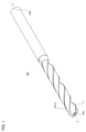
- FIG. 1 is a perspective view of a drill 100.
- FIG. 2 is a front view of the drill 100 seen from the tip 100a side.
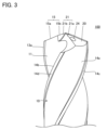
- FIG. 3 is a first enlarged side view of the drill 100.
- FIG. 4 is a second enlarged side view of the drill 100.
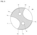
- FIG. 5 is a cross-sectional view of the drill 100 perpendicular to the central axis A.
- FIG. 6 is a cross-sectional view taken along VI-VI in FIG.
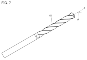
- FIG. 7 is a first schematic diagram showing a method of measuring the first radius of curvature R1 and the second radius of curvature R2.
- FIG. 8 is a second schematic diagram showing a method of measuring the first radius of curvature R1 and the second radius of curvature R2.
- FIG. 9 is a sectional view of a drill 100 in a modified example.
- the present disclosure has been made in view of the problems of the prior art as described above. More specifically, the present disclosure provides a drill that can suppress chipping on the flank surface even under high-feed cutting conditions.
- the drill according to the embodiment includes a flank face, a rake face, and a main cutting edge located on the ridgeline of the rake face and the flank face.
- the main cutting edge has, in a cross-sectional view orthogonal to the extending direction of the main cutting edge, a first curved portion connected to the flank surface and a second curved portion connected to the rake surface.
- the first radius of curvature of the first curved portion is larger than the second radius of curvature of the second curved portion.
- the first radius of curvature may be 1.5 or more times the second radius of curvature and no more than 0.07 mm.
- the second radius of curvature may be 0.02 mm or more and 0.05 mm or less. According to the drill (2) above, it is possible to further suppress chipping on the flank surface even under high feed cutting conditions.
- the main cutting edge further has a linear connecting part that continues to the first curved part and the second curved part in a cross-sectional view perpendicular to the main cutting edge. You may do so.
- the width of the cutting edge treatment can be easily adjusted.
- the width of the connecting portion may be 0.05 mm or less.
- the main cutting edge has a curved connection portion that is continuous with the first curved portion and the second curved portion in a cross-sectional view orthogonal to the extending direction of the main cutting edge. It may further have.
- the third radius of curvature of the connecting portion may be larger than the first radius of curvature. According to the drill (5) above, the width of the cutting edge treatment can be easily adjusted.
- the cutting method includes a step of cutting a workpiece using a drill.
- the drill has a flank face, a rake face, and a main cutting edge located at the ridgeline of the rake face and the flank face.
- the main cutting edge has, in a cross-sectional view orthogonal to the extending direction of the main cutting edge, a first curved portion connected to the flank surface and a second curved portion connected to the rake surface.
- the first radius of curvature of the first curved portion is larger than the second radius of curvature of the second curved portion.
- the cutting process is performed under the condition that the feed rate per drill bit is 5% or more of the drill bit diameter. According to the cutting method (6) above, it is possible to suppress chipping on the flank surface even under high feed cutting conditions.
- the drill according to the embodiment is referred to as a drill 100.
- FIG. 1 is a perspective view of a drill 100.
- the center axis of the drill 100 is defined as a center axis A.
- the drill 100 has a tip 100a and a rear end 100b in the direction of the central axis A.
- the rear end 100b is the end opposite to the tip 100a.
- the drill 100 is made of cemented carbide, for example.
- Cemented carbide is a sintered body of metal carbide grains containing a binder.
- the metal carbide particles are, for example, tungsten carbide (WC) particles, and the binder is, for example, cobalt (Co).
- FIG. 2 is a front view of the drill 100 seen from the tip 100a side.
- FIG. 3 is a first enlarged side view of the drill 100.
- FIG. 4 is a second enlarged side view of the drill 100.
- the drill 100 has an outer circumferential surface 10.
- a flute 11 and a flute 12 are formed on the outer peripheral surface 10.
- the flutes 11 and 12 extend spirally around the central axis A from the tip 100a toward the rear end 100b.
- the flute 11 and the flute 12 are grooves for discharging chips cut out by a cutting edge 15 and a cutting edge 16, which will be described later.
- the outer peripheral surface 10 has a land 13 and a land 14.
- Land 13 is a portion of outer peripheral surface 10 between flute 11 and flute 12.
- the land 14 is a part of the outer peripheral surface 10 between the flute 11 and the flute 12 that is different from the land 13.
- the end of the land 13 on the flute 11 side is defined as a leading edge 13a, and the end of the land 13 on the flute 12 side is defined as a heel 13b.
- the end of the land 14 on the flute 12 side is defined as a leading edge 14a, and the end of the land 14 on the flute 11 side is defined as a heel 14b.
- the land 13 has a main margin 13c, a submargin 13d, and a second chamfer surface 13e.
- the main margin 13c is located at the end of the land 13 on the leading edge 13a side.
- the sub-margin 13d is located at the end of the land 13 on the heel 13b side.
- the main margin 13c and the submargin 13d protrude outward in the radial direction from the second cut surface 13e. That is, a step exists at the boundary between the main margin 13c and the second chamfer surface 13e and the boundary between the submargin 13d and the second chamfer surface 13e.
- the land 14 has a main margin 14c, a submargin 14d, and a second chamfer surface 14e.
- the main margin 14c is located at the end of the land 14 on the leading edge 14a side.
- the sub-margin 14d is located at the end of the land 14 on the heel 14b side.
- the main margin 14c and the submargin 14d protrude outward in the radial direction from the second cut surface 14e. In other words, a step exists at the boundary between the main margin 14c and the second chamfer surface 14e and at the boundary between the submargin 14d and the second chamfer surface 14e.
- the drill 100 has a cutting edge 15 and a cutting edge 16 on the tip 100a side.
- the cutting edge 15 extends from the end of the leading edge 13a on the tip 100a side toward the central axis A side in a front view seen from the tip 100a side.
- the cutting edge 16 extends from the end of the leading edge 14a on the tip 100a side toward the central axis A side in a front view seen from the tip 100a side.
- the cutting edge 15 has a main cutting edge 15a and a thinning cutting edge 15b.
- the main cutting edge 15a is a portion of the cutting edge 15 extending from the end of the leading edge 13a on the tip 100a side.
- the main cutting edge 15a has a flute 11 connected to it from the side opposite to a first flank 17, which will be described later.
- the main cutting edge 15a is located on the ridge line between the flute 11 and the first flank 17, and the part of the flute 11 that is continuous with the main cutting edge 15a is on the rake face of the main cutting edge 15a. It has become.
- Thinning cutting edge 15b is a portion of cutting edge 15 extending from the end of main cutting edge 15a opposite to leading edge 13a.
- the cutting edge 16 has a main cutting edge 16a and a thinning cutting edge 16b.
- the main cutting edge 16a is a portion of the cutting edge 16 extending from the end of the leading edge 14a on the tip 100a side.
- a flute 12 is continuous to the main cutting edge 16a from the side opposite to a first flank surface 19, which will be described later.
- the main cutting edge 16a is located on the ridge line between the flute 12 and the first flank 19, and the part of the flute 12 that is continuous with the main cutting edge 16a is on the rake face of the main cutting edge 16a. It has become.
- Thinning cutting edge 16b is a portion of cutting edge 16 that extends from the end of main cutting edge 16a opposite to leading edge 14a.
- the drill 100 has a first flank 17, a second flank 18, a first flank 19, a second flank 20, a thinning surface 21, a thinning surface 22, an oil hole 23, and an oil hole on the tip 100a side. It further has a hole 24.
- the first flank surface 17 is continuous with the cutting edge 15.
- the second flank 18 is continuous with the first flank 17 from the side opposite to the cutting edge 15.
- the first flank 19 is continuous with the cutting edge 16.
- the second flank surface 20 is continuous with the first flank surface 19 from the side opposite to the cutting edge 16.
- the thinning surface 21 and the thinning surface 22 are surfaces formed to reduce the core thickness of the drill 100 at the tip 100a (surfaces formed by thinning the tip 100a).
- the thinning surface 21 and the thinning surface 22 are surfaces formed by performing X-shaped thinning on the tip 100a.
- the thinning surface 21 has a thinning heel surface 21a and a thinning rake surface 21b.
- the thinning heel surface 21a is continuous with the flute 11 and the second flank surface 20. That is, the thinning heel surface 21a is a portion of the thinning surface 21 located on the heel 14b side.
- the thinning rake face 21b continues to the cutting edge 15 from the side opposite to the first flank face 17. That is, the thinning cutting edge 15b is located on the ridgeline between the first flank face 17 and the thinning rake face 21b.
- the thinning surface 22 has a thinning heel surface 22a and a thinning rake surface 22b.
- the thinning heel surface 22a is continuous with the flute 12 and the second flank surface 18. That is, the thinning heel surface 22a is a portion of the thinning surface 22 located on the heel 13b side.
- the thinning rake face 22b continues to the cutting edge 16 from the side opposite to the first flank face 19. That is, the thinning cutting edge 16b is located on the ridgeline between the first flank surface 19 and the thinning rake surface 22b.
- FIG. 5 is a cross-sectional view of the drill 100 perpendicular to the central axis A.
- the oil hole 23 and the oil hole 24 are formed inside the drill 100.
- the oil hole 23 is open in the second flank 18 (see FIG. 2).
- the oil hole 24 is open in the second flank 20 (see FIG. 2).
- the oil hole 23 and the oil hole 24 extend from the tip 100a toward the rear end 100b while being twisted in accordance with the twisting of the flutes 11 and 12 inside the drill 100. Note that the oil hole 23 and the oil hole 24 may not be formed in the drill 100.
- FIG. 6 is a cross-sectional view taken along VI-VI in FIG. 2.
- FIG. 6 shows a cross section perpendicular to the extending direction of the main cutting edge 15a.
- the main cutting edge 15a has a first curved portion 15aa and a second curved portion 15ab in a cross-sectional view orthogonal to the extending direction of the main cutting edge 15a.
- the first curved portion 15aa is continuous with the first flank 17.
- the second curved portion 15ab is continuous with the flute 11.
- the first curved portion 15aa and the second curved portion 15ab are curved in a cross-sectional view orthogonal to the extending direction of the main cutting edge 15a.
- the first curved portion 15aa and the second curved portion 15ab preferably have a partially arcuate shape in a cross-sectional view orthogonal to the extending direction of the main cutting edge 15a.
- the first curved portion 15aa and the second curved portion 15ab are continuous with each other.
- the radius of curvature of the first curved portion 15aa is defined as the first radius of curvature R1.
- the radius of curvature of the second curved portion 15ab is defined as a second radius of curvature R2.
- the first radius of curvature R1 is larger than the second radius of curvature R2.
- the first radius of curvature R1 is preferably at least 1.5 times the second radius of curvature R2 and at most 0.07 mm.
- the second radius of curvature R2 is preferably 0.02 mm or more and 0.05 mm or less.
- the first radius of curvature R1 and the second radius of curvature R2 may be measured at any position on the main cutting edge 15a.
- the first radius of curvature R1 may not be constant within the range of the first curved portion 15aa, and the second radius of curvature R2 may not be constant within the range of the second curved portion 15ab. In this case, if the minimum value of the first radius of curvature R1 is larger than the maximum value of the second radius of curvature R2, the relationship "the first radius of curvature R1 is larger than the second radius of curvature R2" is satisfied. This means that it has been done.
- FIG. 7 is a first schematic diagram showing a method of measuring the first radius of curvature R1 and the second radius of curvature R2.
- the drill 100 when measuring the first radius of curvature R1 and the second radius of curvature R2, first, the drill 100 is arranged so as to be inclined with respect to the horizontal direction. If the angle between the central axis A and the horizontal direction is an inclination angle ⁇ , the drill 100 is arranged so that the inclination angle ⁇ is ⁇ 20° of the helix angle of the flute 11 (flute 12). Note that the torsion angle of the flute 11 (flute 12) is the angle between the extending direction of the flute 11 (flute 12) and the central axis A.
- the contour near the main cutting edge 15a is measured using a contourer (C3000 manufactured by Mitutoyo Co., Ltd.).
- the measurement software is FORMTRACEPAK for Windows Version 5.202
- the stylus is a conical stylus (SPH-77/12AAE867 manufactured by Mitutoyo Co., Ltd.).
- the measurement pitch is 1.0 ⁇ m
- the measurement speed is 0.02 mm/sec. Note that the measurement pitch is the distance between adjacent measurement points.
- the contourer is scanned along a direction perpendicular to the extending direction of the main cutting edge 15a at the measurement position.
- the intersection between the first curved portion 15aa and the first flank 17 and the intersection between the second curved portion 15ab and the flute 11 are calculated based on the above contour.
- FIG. 8 is a second schematic diagram showing a method of measuring the first radius of curvature R1 and the second radius of curvature R2.
- FIG. 8 shows a cross section at a position corresponding to VI-VI in FIG. 2 as an example.
- a straight line parallel to the first flank 17 and 1 ⁇ m away from the first flank 17 to the inside of the drill 100 is defined as a first imaginary straight line L1.
- a straight line that is parallel to the part of the flute 11 that continues to the main cutting edge 15a (that is, the rake face of the main cutting edge 15a) and that is 1 ⁇ m away from the part to the inside of the drill 100 is defined as a second virtual straight line L2.
- intersection between the first imaginary straight line L1 and the above contour is regarded as the intersection between the first curved part 15aa and the first flank 17 (first intersection CP1), and the intersection between the second imaginary straight line L2 and the above contour
- intersection point is regarded as the intersection point between the second curved portion 15ab and the flute 11 (second intersection point CP2).
- the first radius of curvature R1 and the second radius of curvature R2 are calculated based on the above contour between the first intersection point CP1 and the second intersection point CP2. More specifically, first, the center of curvature of the curve indicated by the 20 measurement points closest to the first intersection CP1 is calculated based on the least squares method. Next, the average value of the distances between the center of curvature and each of the 20 measurement points closest to the first intersection CP1 is calculated. This average value becomes the first radius of curvature R1. The second radius of curvature R2 is also calculated in the same manner.
- the center of curvature of the curve indicated by the 20 measurement points closest to the second intersection CP2 is calculated based on the least squares method, and the average distance between each of the 20 measurement points and the center of curvature is calculated.
- the value is defined as the second radius of curvature R2.
- the main cutting edge 16a has the same configuration as the main cutting edge 15a. More specifically, the main cutting edge 16a has a first curved portion 16aa in a curved shape (partial arc shape) continuous to the first flank 19 and a curved line continuous to the flute 12 in a cross-sectional view perpendicular to the main cutting edge 16a. (partially arcuate) second curved portion 16ab. The radius of curvature of the first curved portion 16aa is larger than the radius of curvature of the second curved portion 16ab.
- the radius of curvature of the first curved portion 16aa is preferably 1.5 times or more and 0.07 mm or less than the radius of curvature of the second curved portion 16ab, and the radius of curvature of the second curved portion 16ab is 0.2 mm or more and 0.05 mm or less. It is preferable that
- FIG. 9 is a sectional view of a drill 100 in a modified example.
- FIG. 9 shows a cross section at a position corresponding to VI-VI in FIG.
- the main cutting edge 15a may further include a connecting portion 15ac in a cross-sectional view orthogonal to the extending direction of the main cutting edge 15a.
- the connecting portion 15ac is continuous with the first curved portion 15aa and the second curved portion 15ab.
- the connecting portion 15ac is, for example, linear in a cross-sectional view orthogonal to the extending direction of the main cutting edge 15a.
- the width W of the connecting portion 15ac is preferably 0.05 mm or less.
- the connecting portion 15ac may be curved (partially arcuate) in a cross-sectional view orthogonal to the extending direction of the main cutting edge 15a.
- the radius of curvature of the connecting portion 15ac is larger than the first radius of curvature R1.
- Cutting using the drill 100 is performed by rotating the drill 100 around the central axis A while bringing the cutting edges 15 and 16 into contact with the workpiece.
- the feed amount per blade is preferably 5% or more of the blade diameter D of the drill 100.
- the blade diameter D is the circumscribed circle of the cutting edge 15 (cutting edge 16) in a front view seen from the tip 100a side (see FIG. 2). Note that the feed amount per blade is, for example, 8% or less of the blade diameter D.
- the drill 100 is used, for example, for cutting carbon steel such as S50C.
- the radius of curvature of the round honing is automatically determined.
- the width for cutting edge treatment cannot be made excessively large because it also affects chip disposal and cutting resistance. Therefore, in the drill according to Comparative Example 1, it is not possible to increase the width of the cutting edge treatment from the viewpoint of chip disposal and cutting resistance, and as a result, the radius of curvature of round honing cannot be increased.
- the strength of the cutting edge 15a becomes insufficient.
- the first radius of curvature R1 and the second radius of curvature R2 are not automatically determined by the width of the cutting edge treatment.
- chipping is likely to occur on the first flank surface 17.
- the first radius of curvature R1 and the second radius of curvature R2 are not automatically determined by the width of the cutting edge treatment.
- the radius of curvature of the main cutting edge 15a is larger on the flank side (that is, the first radius of curvature R1 is larger than the second radius of curvature R2), so the high feed cutting conditions Even if the first flank surface 17 is subjected to cutting, chipping is unlikely to occur on the first flank surface 17.
- the first flank surface 17, chipping becomes more difficult to occur.
- the main cutting edge 15a of the drill 100 further includes the connecting portion 15ac, it becomes easy to adjust the width in which the cutting edge treatment is performed.
- Samples 1 to 5 were used as drill samples for the cutting test.
- the first radius of curvature R1 was made smaller than the second radius of curvature R2. More specifically, in sample 1, the first radius of curvature R1 and the second radius of curvature R2 are respectively 0.024 mm and 0.065 mm, and in sample 2, the first radius of curvature R1 and the second radius of curvature R2 are respectively 0.024 mm and 0.065 mm. 029mm and 0.079mm.
- samples 1 to 5 were used to cut workpieces.
- the work material for cutting was S50C.
- the cutting process was performed using NV5000 ⁇ 1A/40 manufactured by DMG Mori Seiki Co., Ltd.
- the cutting process was performed by forming a through hole with a depth of 38 mm under the conditions of a cutting speed of 140 m/min and a feed rate per tooth of 0.40 mm/rev (5% of the blade diameter D). Ta.
- coolant was supplied through the oil holes 23 and 24.
- the cutting life of each sample was evaluated by the cutting distance until chipping occurred on the first flank 17. Note that chipping was considered to have occurred on the first flank surface 17 when the area of the chip that occurred on the first flank surface 17 was 0.00025 mm 2 or more.
Landscapes
- Engineering & Computer Science (AREA)
- Mechanical Engineering (AREA)
- Drilling Tools (AREA)
Abstract
L'invention concerne un foret comprenant une surface de flanc, une surface de coupe et un bord de découpe principal sur l'arête entre la surface de flanc et la surface de coupe. Le bord de découpe principal comprend une première partie incurvée ayant une forme incurvée et continue avec la surface de flanc, et une seconde partie incurvée ayant une forme incurvée et continue avec la surface de coupe, dans une vue en coupe transversale orthogonale à la direction d'extension du bord de découpe principal. Un premier rayon de courbure de la première partie incurvée est supérieur à un second rayon de courbure de la seconde partie incurvée.
Priority Applications (1)
| Application Number | Priority Date | Filing Date | Title |
|---|---|---|---|
| PCT/JP2022/025935 WO2024004075A1 (fr) | 2022-06-29 | 2022-06-29 | Foret et procédé de découpe |
Applications Claiming Priority (1)
| Application Number | Priority Date | Filing Date | Title |
|---|---|---|---|
| PCT/JP2022/025935 WO2024004075A1 (fr) | 2022-06-29 | 2022-06-29 | Foret et procédé de découpe |
Publications (1)
| Publication Number | Publication Date |
|---|---|
| WO2024004075A1 true WO2024004075A1 (fr) | 2024-01-04 |
Family
ID=89382374
Family Applications (1)
| Application Number | Title | Priority Date | Filing Date |
|---|---|---|---|
| PCT/JP2022/025935 WO2024004075A1 (fr) | 2022-06-29 | 2022-06-29 | Foret et procédé de découpe |
Country Status (1)
| Country | Link |
|---|---|
| WO (1) | WO2024004075A1 (fr) |
Citations (5)
| Publication number | Priority date | Publication date | Assignee | Title |
|---|---|---|---|---|
| JPH09500335A (ja) * | 1993-11-15 | 1997-01-14 | ロジャーズ ツール ワークス インク | 仕上げ処理された切削刃を持つドリルの表面脱炭 |
| JP2002370107A (ja) * | 2001-06-15 | 2002-12-24 | Osg Corp | ダイヤモンド被覆切削工具 |
| JP2014008549A (ja) * | 2012-06-28 | 2014-01-20 | Sumitomo Electric Hardmetal Corp | ドリル |
| JP2015123552A (ja) * | 2013-12-26 | 2015-07-06 | 三菱マテリアル株式会社 | ドリル用インサートおよび刃先交換式ドリル |
| WO2020075698A1 (fr) * | 2018-10-11 | 2020-04-16 | 株式会社不二越 | Foret revêtu d'un film dur |
-
2022
- 2022-06-29 WO PCT/JP2022/025935 patent/WO2024004075A1/fr unknown
Patent Citations (5)
| Publication number | Priority date | Publication date | Assignee | Title |
|---|---|---|---|---|
| JPH09500335A (ja) * | 1993-11-15 | 1997-01-14 | ロジャーズ ツール ワークス インク | 仕上げ処理された切削刃を持つドリルの表面脱炭 |
| JP2002370107A (ja) * | 2001-06-15 | 2002-12-24 | Osg Corp | ダイヤモンド被覆切削工具 |
| JP2014008549A (ja) * | 2012-06-28 | 2014-01-20 | Sumitomo Electric Hardmetal Corp | ドリル |
| JP2015123552A (ja) * | 2013-12-26 | 2015-07-06 | 三菱マテリアル株式会社 | ドリル用インサートおよび刃先交換式ドリル |
| WO2020075698A1 (fr) * | 2018-10-11 | 2020-04-16 | 株式会社不二越 | Foret revêtu d'un film dur |
Similar Documents
| Publication | Publication Date | Title |
|---|---|---|
| US9511424B2 (en) | Drill | |
| US8382404B2 (en) | Drill | |
| EP3195967B1 (fr) | Foret | |
| JP5816364B2 (ja) | 3枚刃ドリル | |
| US9492877B2 (en) | Drill | |
| JP2003334716A (ja) | スローアウェイチップ及び切削工具 | |
| JP2011073129A (ja) | 穴あけ用ドリル | |
| US7018144B2 (en) | Drill | |
| JP5368384B2 (ja) | 深穴加工用ドリル | |
| JP3483859B2 (ja) | スローアウェイ式チップ、及び、そのスローアウェイ式チップが装着されるフライス工具 | |
| JP6870336B2 (ja) | ドリル | |
| WO2024004075A1 (fr) | Foret et procédé de découpe | |
| JP3337804B2 (ja) | エンドミル | |
| JP3929901B2 (ja) | ドリル | |
| WO2023243004A1 (fr) | Foret | |
| JP3933044B2 (ja) | ドリル | |
| JP2024006982A (ja) | ドリル及び切削方法 | |
| JP6750790B1 (ja) | ドリル | |
| WO2012053090A1 (fr) | Foret à trois lames | |
| CN113993644A (zh) | 钻头 | |
| JP4053295B2 (ja) | 穴明け工具 | |
| US11951553B2 (en) | Rotatable cutting head having tip portion with three radially extending cutting edges forming a rectilinear rotational profile | |
| US20220339713A1 (en) | Rotatable Cutting Head Having Tip Portion with Radially Extending Cutting Edges Forming a Cutting Profile Having Concave and Convex Sub-Portions | |
| JP3657546B2 (ja) | ドリル | |
| WO2021181518A1 (fr) | Alésoir |
Legal Events
| Date | Code | Title | Description |
|---|---|---|---|
| 121 | Ep: the epo has been informed by wipo that ep was designated in this application |
Ref document number: 22949350 Country of ref document: EP Kind code of ref document: A1 |