WO2024004042A1 - ロボット制御装置 - Google Patents
ロボット制御装置 Download PDFInfo
- Publication number
- WO2024004042A1 WO2024004042A1 PCT/JP2022/025797 JP2022025797W WO2024004042A1 WO 2024004042 A1 WO2024004042 A1 WO 2024004042A1 JP 2022025797 W JP2022025797 W JP 2022025797W WO 2024004042 A1 WO2024004042 A1 WO 2024004042A1
- Authority
- WO
- WIPO (PCT)
- Prior art keywords
- robot
- function
- safety
- safety function
- unit
- Prior art date
- Legal status (The legal status is an assumption and is not a legal conclusion. Google has not performed a legal analysis and makes no representation as to the accuracy of the status listed.)
- Ceased
Links
Images


Classifications
-
- B—PERFORMING OPERATIONS; TRANSPORTING
- B25—HAND TOOLS; PORTABLE POWER-DRIVEN TOOLS; MANIPULATORS
- B25J—MANIPULATORS; CHAMBERS PROVIDED WITH MANIPULATION DEVICES
- B25J19/00—Accessories fitted to manipulators, e.g. for monitoring, for viewing; Safety devices combined with or specially adapted for use in connection with manipulators
- B25J19/06—Safety devices
- B25J19/066—Redundant equipment
-
- B—PERFORMING OPERATIONS; TRANSPORTING
- B25—HAND TOOLS; PORTABLE POWER-DRIVEN TOOLS; MANIPULATORS
- B25J—MANIPULATORS; CHAMBERS PROVIDED WITH MANIPULATION DEVICES
- B25J9/00—Program-controlled manipulators
- B25J9/16—Program controls
- B25J9/1674—Program controls characterised by safety, monitoring, diagnostic
- B25J9/1676—Avoiding collision or forbidden zones
Definitions
- the present invention relates to a robot control device.
- Patent Document 1 states, "In a control system that controls a device, a standard function section that controls the operation of the device, a safety function section that performs control to manage the safety of the device, and a standard function section that controls the operation of the device.” a standard function setting section for setting setting items related to control by the safety function section; and a safety function setting section for setting setting items related to control by the safety function section, the standard function setting section or the safety function.
- a control system characterized in that the control system is automatically set to predetermined contents corresponding to the contents of the first setting item.'' (Claim 1).
- Patent Document 2 relates to a robot control device and states, ⁇ In the invention according to claim 2, the servo motor of the robot is driven by the operation control of the servo control section, and the position detection section changes in accordance with the drive of the servo motor.
- the operating position (the position, angle, position change amount, angle change amount, etc. of each part of the robot that is changed by the servo motor) is detected.
- each processing calculation unit converts the detected operating position into a preset allowable operating position. (Paragraph 0012) states that the servo motor is stopped even if only one of the processing calculation units determines that it is outside the allowable operating position.
- Patent Document 3 relates to a manipulator motion restriction device, and states that "region L data for determining the presence or absence of interference in the motion restriction region L by the interference determination unit 11 is defined by a function as a region included in a polyhedron, and this region L data is defined as a region included in a polyhedron.
- the intended purpose was achieved by configuring the system to determine the presence or absence of interference of the manipulator 12 based on the data (abstract).
- Patent Document 4 states, ⁇ Even if the shape, posture, and load conditions of the robot arm change, the position of the joint movement of the robot arm is determined by a position detector so that the joint movement speed of the arm at the time of brake release is within a certain value. The joint movement speed is calculated based on the amount of change in the joint movement position and elapsed time, and compared with the allowable movement speed to control the release and locking of the brake.'' (Abstract)
- a robot control device may provide a function of monitoring the operating state of a robot as one of the standard functions such as normal robot control.
- the safety function and the function of monitoring the operating state of the robot based on standard functions are generally provided as separate and independent functions.
- a robot control device is desired that allows a user to smoothly switch between a safety function and a function to monitor the operating state of a robot based on standard functions.
- One aspect of the present disclosure is a robot control device that controls a robot, including a standard function unit that controls the operation of standard functions of the robot and has a function of monitoring the robot; A safety function unit that controls safety functions for managing the safety of a robot, and setting items that are commonly used in the control of the safety function by the safety function unit and the monitoring of the robot by the standard function unit. a setting section for setting setting information; and a switching section for switching between operation of the safety function by the safety function section based on the setting information and monitoring of the robot based on the setting information by the standard function section.
- This is a robot control device equipped with.
- the user can smoothly switch between the safety function and the robot monitoring function based on the standard function.
- FIG. 1 is a diagram showing the equipment configuration of a robot system according to an embodiment.
- FIG. 3 is a diagram illustrating a function of checking an operating area by the robot control device.
- FIG. 3 is a diagram for explaining an example of an interference check function by the robot control device.
- FIG. 7 is a diagram for explaining another example of the interference check function by the robot control device. It is a diagram showing an example of the hardware configuration of a robot control device and an external input device.
- FIG. 2 is a conceptual diagram showing the configuration and cooperation of safety functions and standard functions.
- FIG. 2 is a functional block diagram of a robot control device.
- FIG. 3 is a diagram illustrating an example of a UI screen for setting parameters related to position checking.
- FIG. 3 is a diagram showing an example of a UI screen for setting parameters related to speed check.
- FIG. 4 is a diagram for explaining the flow of operations when switching from a safety function to a standard function on a UI screen.
- FIG. 3 is a diagram for explaining the flow of operation when switching from a standard function to a safety function on a UI screen.
- FIG. 6 is a diagram for explaining an operation when changing setting parameters on a UI screen in which a standard function is selected.
- FIG. 12B is a diagram schematically showing the state of an actual operation check when the settings shown in FIG. 12A are changed.
- FIG. 1 is a diagram showing the equipment configuration of a robot system 100 according to an embodiment.
- the robot system 100 includes a robot 10, a robot control device 20 that controls the robot 10, and an external input device 40 connected to the robot control device 20.
- the external input device 40 is, for example, a teaching pendant.
- an information processing device such as a tablet terminal, a smartphone, or a PC (personal computer) may be used as the external input device 40.
- the robot 10 is assumed to be a six-axis articulated robot. Note that various types of robots may be used as the robot 10 depending on the work object, such as a parallel link type robot or a dual-arm robot.
- J1 axis The joint axes of the robot 10 will be referred to as J1 axis, J2 axis, J3 axis, J4 axis, J5 axis, and J6 axis in order from the base side.
- J1 axes to J6 axes correspond to axes of rotation by actuators provided for the respective axes.
- FIG. 1 the rotation directions of each axis are indicated by arrows J1 to J6.
- the robot 10 can perform desired tasks using an end effector attached to its wrist.
- the end effector is an external device that can be replaced depending on the application, and is, for example, a hand, a welding gun, a tool, or the like.
- FIG. 1 shows an example in which a hand is used as an end effector.
- the robot control device 20 has a safety function for managing the safety of the robot 10 (a function to stop the robot when an abnormality in the position or speed of the robot is detected). etc.).
- This safety function is configured to meet, for example, the requirements of international safety standards ISO13849-1 and IEC61508, and to be executed under a highly reliable operating environment.
- safety functions can be executed under the control of a dedicated processor that is separate from the processor that controls standard functions, or dual processors can double monitor the position and speed of each axis motor to detect abnormalities.
- a configuration is used that allows the power of the servo control to be cut off in a separate and independent system when the servo control is detected. Additionally, safety functions generally pose a burden on operation, such as requiring an authentication process or restarting the system to change or apply parameter settings.
- the robot control device 20 is equipped with a function of monitoring the position and speed of the motor of each axis and detecting abnormalities as one of the standard functions of a single processor that performs normal robot control. Ru. This function has the aspect that the operational burden is low because it does not have to satisfy the requirements regarding the operating environment and the protection level of the setting parameters like the above-mentioned safety function.
- FIG. 2 shows an example in which a motion region R1 in which the robot 10 can move is set around the robot 10.
- the robot 10 is stopped when the robot 10 performs a motion that exceeds the motion range R1.
- a cylindrical or spherical model (robot model 101M) is set around the robot 10 so as to cover the arms, joints, and tool parts, and this robot model 101M is set in the operating area R1.
- the robot 10 may be stopped when the robot 10 performs an operation exceeding the above range.
- FIG. 3 shows a situation where a plurality of robots 10A and 10B perform work on a workpiece W.
- the control device of the robot 10A acquires the position information of the robot 10B and stops the robot 10A when the robot 10A performs an operation that interferes with the robot 10B.
- FIG. 4 shows an interference check between the robot 10 and peripheral equipment.
- a model R3 representing the peripheral device D1 is set, and a model R2 representing the peripheral device D2 is set.
- FIG. 5 shows an example of the hardware configuration of the robot control device 20 and external input device 40.
- the robot control device 20 is a general robot controller in which a processor 21 is connected to a memory 22 (ROM, RAM, non-volatile memory, etc.), various input/output interfaces 23, an operation section 24 including various operation switches, etc. via a bus. It may have a configuration as a computer.
- the input/output interface 23 includes a network interface, a serial interface, a sensor signal interface, and other external device interfaces. Note that when the robot control device 20 is configured as a dual CPU system, a processor 28 that can exchange information with the processor 21 is installed. Like the processor 21, the processor 28 may be connected to a memory 22 (ROM, RAM, nonvolatile memory, etc.), various input/output interfaces 23, an operation section 24 including various operation switches, etc. via a bus.
- the external input device 40 includes a memory 42 (ROM, RAM, non-volatile memory, etc.), a display section 43, an operation section 44 including input devices such as a keyboard (or software keys), and various input/output devices for the processor 41. It may have a general computer configuration in which the interface 45 and the like are connected via a bus.
- the input/output interface 45 includes a network interface, a serial interface, and other external device interfaces.
- the robot control device 20 allows switching between the safety function and the standard function, and allows the user to select the safety function and the standard function as necessary.
- the configuration parameters are shared from the user's perspective.
- FIG. 6 is a conceptual diagram showing the configuration and cooperation of safety functions and standard functions.
- the area surrounded by a rectangular frame in the figure represents the safety function.
- Standard functions are shown on the left side of the rectangular frame in the figure.
- Setting parameters 202 can be set on a safety function screen 201 provided on the safety function.
- the safety function parameters 211 are protected so that they cannot be edited directly.
- the setting parameters 202 can be used as the safety function parameters 211 used by the safety function 210.
- the application process includes an authentication process such as password entry.
- the setting parameters 202 are also applied as standard function parameters 221 for the standard functions 220. In this case, an authentication process may not be included.
- the safety function and standard function check function include the following.
- Position abnormality detection function Inspects the position of the robot and checks whether the robot (or the robot model set for the robot) is not exceeding its operating range, or whether the robot (or the robot model set for the robot) is A function that checks whether you are entering a restricted area.
- robot position may include any position from the base of the robot to the tip of the arm and the tool.
- An abnormality can also be detected when a robot tool (tool model) or arm (arm shape model) performs a motion that exceeds the operating range.
- the positional abnormality detection function may include a function of checking whether the position of each axis of the robot is out of a set operating range (angular range).
- Posture abnormality detection function For example, the posture of the flange surface at the tip of the robot arm or the tool (rotational angular position around the X, Y, and Z axes in the reference coordinate system) is determined as the reference posture (W, P, R). A function to compare and check for abnormalities.
- Model interference detection function A function to check whether the set models are interfering with each other.
- Speed abnormality detection function A function to check whether a predetermined control part of the robot (TCP (tool center point), etc.) exceeds a set speed limit. Also.
- the speed abnormality detection function may include a function of checking whether the speed of each axis exceeds a set speed limit.
- FIG. 7 is a functional block diagram of the robot control device 20. As shown in FIG. 7, the robot control device 20 includes a switching unit 241 that provides a function to switch between a safety function and a standard function.
- the robot control device 20 includes a setting unit 240 for setting setting information including setting items that are commonly used for safety functions and monitoring the operation of the robot 10 using standard functions.
- the setting section 240 includes a region setting section 242 , a posture limit setting section 243 , a model setting section 244 , and a speed limit setting section 245 .
- the area setting unit 242 provides a function of setting the position and size of the operating area or restricted area.
- the posture limit setting unit 243 provides a function for setting the reference posture (W, P, R) of the flange surface or tool and the upper limit value (deg) of posture change from there.
- the model setting unit 244 provides a function to set a model that covers a robot, robot tool, or peripheral device. In area checks (position checks) and model interference checks, these models are used to calculate violation checks.
- the speed limit setting unit 245 provides a function of setting speed limit values for a predetermined control part (TCP, etc.) of the robot and each axis of the robot.
- the robot control device 20 has a safety function section 260 that controls safety functions.
- the safety function section 260 includes a position/posture speed calculation section 261 , a position abnormality detection section 262 , a posture abnormality detection section 263 , a model interference detection section 264 , and a speed abnormality detection section 265 .
- the robot control device 20 also includes a stop command section 270.
- the position/posture/velocity calculation unit 261 calculates the position of the robot 10 and the position of each axis of the robot 10 through kinematic calculations based on signals from the sensor unit (encoder, etc.) 11 mounted on each joint axis of the robot 10. , the speed of the robot 10, and the speed of each axis of the robot 10 can be determined. Further, the position/posture/velocity calculation section 261 can determine the posture of the flange surface of the robot 10 or the tool based on the output of the sensor section 11 for each axis.
- the position abnormality detection unit 262 checks whether the position of the robot 10 does not exceed the operating area or enter the restricted area, based on the position of the robot 10 obtained by the position/posture/velocity calculation unit 261. do. When an abnormality is detected, the positional abnormality detection unit 262 notifies the stop command unit 270 of the abnormality.
- the posture abnormality detection section 263 checks whether the change in the posture of the robot 10 obtained by the position/posture speed calculation section 261 with respect to the reference posture (W, P, R) does not exceed an upper limit value. When an abnormality is detected, the posture abnormality detection unit 263 notifies the stop command unit 270 of the abnormality.
- the model interference detection unit 264 checks whether or not interference occurs between the set models, based on the positions calculated by the position/posture/velocity calculation unit 261 for the set models. If an abnormality is detected, the model interference detection unit 264 notifies the stop command unit 270 of the abnormality.
- the speed abnormality detection unit 265 checks whether the speed of the robot 10 obtained by the position/posture speed calculation unit 261 or the speed of each axis of the robot 10 does not exceed a set speed limit value. When an abnormality is detected, the speed abnormality detection unit 265 notifies the stop command unit 270 of the abnormality.
- the stop command unit 270 stops the robot 10 when an abnormality is notified from the position abnormality detection unit 262, the posture abnormality detection unit 263, the model interference detection unit 264, or the speed abnormality detection unit 265.
- the safety function unit 260 may further have a function as a diagnostic unit that diagnoses whether each abnormality detection unit is operating normally in a state where the safety function is activated. This diagnostic function may be performed, for example, by periodically monitoring the status of programs and hardware or monitoring the validity of parameters.
- the robot control device 20 further includes a standard function section 250 that monitors the operation of the robot 10 in the standard function.
- the standard function section 250 includes a position/posture speed calculation section 251 , a position abnormality detection section 252 , a posture abnormality detection section 253 , a model interference detection section 254 , and a speed abnormality detection section 255 .
- the position/posture/velocity calculation unit 251 calculates the position of the robot 10 and the position of each axis of the robot 10 through kinematic calculations based on signals from the sensor unit (encoder, etc.) 11 mounted on each joint axis of the robot 10. , the speed of the robot 10, and the speed of each axis of the robot 10 can be determined. Further, the position/attitude/velocity calculation unit can determine the attitude of the flange surface of the robot 10 or the tool based on the output of the sensor unit 11 for each axis.
- the position abnormality detection unit 252 checks whether the position of the robot 10 does not exceed the operating area or enter the restricted area, based on the position of the robot 10 obtained by the position/posture/velocity calculation unit 251. do. When an abnormality is detected, the positional abnormality detection unit 252 notifies the stop command unit 270 of the abnormality.
- the posture abnormality detection unit 253 checks whether the change in the posture of the robot 10 obtained by the position/posture velocity calculation unit 251 with respect to the reference posture (W, P, R) does not exceed an upper limit value. When an abnormality is detected, the posture abnormality detection unit 253 notifies the stop command unit 270 of the abnormality.
- the model interference detection unit 254 checks whether or not interference occurs between the set models, based on the positions calculated by the position/posture velocity calculation unit 251 for the set models.
- the interference check in the model interference detection unit 254 includes checking for interference between a robot model and a peripheral device model, interference between a tool shape model and an arm shape model in the robot, and the like. If an abnormality is detected, the model interference detection unit 254 notifies the stop command unit 270 of the abnormality.
- the speed abnormality detection unit 255 checks whether the speed of the robot 10 obtained by the position/posture speed calculation unit 251 or the speed of each axis of the robot 10 does not exceed a set speed limit value. When an abnormality is detected, the speed abnormality detection unit 255 notifies the stop command unit 270 of the abnormality.
- the stop command unit 270 stops the robot 10 when an abnormality is notified from the position abnormality detection unit 252, the posture abnormality detection unit 253, the model interference detection unit 254, or the speed abnormality detection unit 255.
- monitoring in functional blocks related to safety functions is performed by the robot control device 20.
- the monitoring function may be implemented with high reliability and high-speed processing capability by executing the monitoring function in duplicate using two processors (processors 21 and 28) built into the computer.
- processors 21 and 28 the processors built into the computer.
- the safety function when an abnormality is detected, the power of the robot's motor may be reliably cut off through two independent paths.
- reliability may be maintained by mutually checking processing contents and data used for processing by two processors.
- self-diagnosis of hardware and software related to the safety function may be performed periodically.
- the standard functions include functional blocks related to monitoring functions (position/attitude/velocity calculation section 251, position abnormality detection section 252, attitude abnormality detection section 253, model interference detection section 254, and speed abnormality detection section). 255) can be executed by one processor (for example, the processor 21 responsible for normal operation control). In this case, it is possible to adopt a configuration in which dual monitoring by two processors, mutual checking, and self-diagnosis as in the case of safety functions are not performed.
- the region setting section 242, the posture limit setting section 243, the model setting section 244, and the speed limit setting section 245 may be configured to accept these parameter settings via a UI (user interface) screen.
- the UI screen may be displayed, for example, on the display screen of the display unit 43 of the external input device 40, and operation input to the UI screen may be received via the operation unit 44.
- the settings on the UI screen 310 shown in FIG. 8 are examples of settings when checking the position of the robot.
- the settings in the monitoring method specification column 311, model specification column 312, and specification column 313 for the position and size of the operating area or restriction area are used for checking in the position abnormality detection units 252 and 262. obtain.
- the specification field 312 for specifying a model can be used for interference checking in the model interference detection units 254 and 264.
- the UI screen 310 is switched to a screen for making settings for position check, posture check, and model interference check, depending on the monitoring method specified in the specification field 311.
- the UI screen 310 further includes a selection field 318 for making settings for switching between safety functions and standard functions. By performing an operation on this selection field 318, it is possible to select whether the setting parameters set on the UI screen 310 are to be used as a safety function or a standard function. Selection of the safety function and standard function via this selection field 318 is provided as a function by the switching unit 241. The switching unit 241 switches between the safety function and the standard function according to the selection in the selection column 318.
- the UI screen 310 in FIG. 8 shows a state in which a safety function is selected.
- multiple UI screens 310 may be prepared.
- the UI screen 300 shown in FIG. 8 is a setting screen of the upper layer, and shows that four parameter sets 301-304 are prepared for each monitoring target.
- a UI screen 310 for detailed settings of the parameter set 301 is shown.
- the UI screen 310 may be opened by, for example, performing an operation of selecting a location of the parameter set 301 on the UI screen 300. In this case, it is possible to select whether to use each parameter set as a safety function or as a standard function.
- the settings for position check, orientation check, and model interference check are entered separately from the UI screen 300. You may implement it so that it is included.
- FIG. 9 shows an example of a UI screen 360 for setting speed check parameters.
- the UI screen 360 is ⁇ Specification field 361 for specifying the direction of speed check ⁇ Specification field 362 for specifying the speed limit value Contains.
- "ALL" is set in the specification column 361 to specify all operating directions as the direction in which the speed check is to be performed, and "250.000 mm/sec" is set as the speed limit value in the specification column 362. It shows.
- the UI screen 360 further includes a selection field 368 for making settings for switching between safety functions and standard functions. By performing an operation on this selection field 368, it is possible to select whether the setting parameters set on the UI screen 360 are to be used as a safety function or as a standard function. Selection of the safety function and standard function via this selection field 368 is provided as a function by the switching unit 241. The switching unit 241 switches between the safety function and the standard function according to the selection in the selection column 368.
- the UI screen 360 in FIG. 9 shows a state in which the safety function is selected.
- FIG. 9 also illustrates an example of the UI 350 of the upper layer when creating a plurality of setting parameters.
- the above-mentioned UI screen 360 is associated with a parameter set 351 that is one of a plurality of parameter sets prepared for this upper layer UI screen 350.
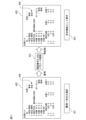
- FIG. 10 is a diagram for explaining the flow of operations when switching from the safety function in the selection column 418 to the standard function on the UI screen 410.
- switching from the safety function to the standard function is selected on the UI screen 410, as shown in box 411.
- the user inputs the password, confirms the parameters, and inputs an application instruction by operating the display screen of the external input device 40 and the operation unit 44.
- the setting parameters in the UI screen 410 can be used as standard function parameters 221, as shown in FIG. 6 (box 413).
- FIG. 11 is a diagram for explaining the flow of operations when switching from the standard function to the safety function in the selection column 428 on the UI screen 420.
- switching from the standard function to the safety function is selected on the UI screen 420, as shown in box 421.
- an application process that includes inputting a PIN number, confirming parameter contents, and restarting as an authentication process (box 422).
- the user inputs the password, confirms the parameters, and inputs an application instruction by operating the display screen of the external input device 40 and the operation unit 44.
- the setting parameters in the UI screen 420 can be used as safety function parameters 211, as shown in FIG. 6 (box 423).
- FIG. 12A is a diagram for explaining the flow of operations for applying parameter setting changes on the UI screen 430 where the standard function is selected.
- box 431 when changing parameters on the UI screen 430 where the standard function is selected and applying the changed parameters, an authentication process is not required as in the case of the safety function.
- the setting parameters changed on the UI screen 430 are immediately applied.
- the parameter application may be applied immediately.
- the position check function based on the parameters on the UI screen 430 before the setting change is a setting for checking the position of the robot model 102M and the motion area R111, as shown on the left side in FIG. 12B.
- the position check function after the setting change on the UI screen 430 is an interference check function between the user model 10M and the restricted area R112, as shown in FIG. 12B.
- the position check function in response to a setting change on the UI screen 430, the position check function immediately switches from the state shown on the left side of FIG. 12B to the state shown on the right side.
- the above configuration allows the user to smoothly switch between the safety function and the robot monitoring function based on the standard function.
- the functional arrangement in the functional block diagram of the robot control device shown in FIG. 7 is an example, and various modifications can be made to the arrangement of these functional blocks.
- the function of the setting section 240 may be arranged on the external input device 40 side.
- a function that integrates the function of the external input device 40 and the function of the robot control device 20 can also be defined as a robot control device.
- the position/posture/velocity calculation units 251 and 261 are arranged in the standard function unit 250 and the safety function unit 260, respectively, but one position/posture/velocity calculation unit is used as the standard function unit.
- the function section 250 and the safety function section 260 may share the same function.
- the functional blocks in FIG. 7 may be realized by the processor of the robot control device executing various software stored in a storage device, or may be realized by a configuration mainly based on hardware such as an ASIC (Application Specific Integrated Circuit). It may be realized by
- the programs that execute various processes in the embodiments described above are stored in various computer-readable recording media (for example, semiconductor memories such as ROM, EEPROM, and flash memory, magnetic recording media, and optical discs such as CD-ROM and DVD-ROM). ) can be recorded.
- semiconductor memories such as ROM, EEPROM, and flash memory
- magnetic recording media such as CD-ROM and DVD-ROM.
- optical discs such as CD-ROM and DVD-ROM.
- robot 11 sensor section 20 robot control device 40 external input device 21, 28 processor 22 memory 23 input/output interface 24 operation section 41 processor 42 memory 43 display section 44 operation section 45 input/output interface 100 robot system 240 setting section 241 switching section 242 Area setting section 243 Posture limit setting section 244 Model setting section 245 Speed limit setting section 250 Standard function section 251 Position/posture speed calculation section 252 Position abnormality detection section 253 Posture abnormality detection section 254 Model interference detection section 255 Speed abnormality detection section 260 Safety function Part 261 Position/Posture Speed Calculation Unit 262 Position Abnormality Detection Unit 263 Posture Abnormality Detection Unit 264 Model Interference Detection Unit 265 Speed Abnormality Detection Unit
Landscapes
- Engineering & Computer Science (AREA)
- Robotics (AREA)
- Mechanical Engineering (AREA)
- Manipulator (AREA)
- Numerical Control (AREA)
Priority Applications (6)
| Application Number | Priority Date | Filing Date | Title |
|---|---|---|---|
| CN202280097199.7A CN119317526A (zh) | 2022-06-28 | 2022-06-28 | 机器人控制装置 |
| JP2024530129A JPWO2024004042A1 (https=) | 2022-06-28 | 2022-06-28 | |
| PCT/JP2022/025797 WO2024004042A1 (ja) | 2022-06-28 | 2022-06-28 | ロボット制御装置 |
| US18/869,282 US20250339966A1 (en) | 2022-06-28 | 2022-06-28 | Robot control device |
| DE112022007120.6T DE112022007120T5 (de) | 2022-06-28 | 2022-06-28 | Robotersteuervorrichtung |
| TW112122402A TW202400380A (zh) | 2022-06-28 | 2023-06-15 | 機器人控制裝置 |
Applications Claiming Priority (1)
| Application Number | Priority Date | Filing Date | Title |
|---|---|---|---|
| PCT/JP2022/025797 WO2024004042A1 (ja) | 2022-06-28 | 2022-06-28 | ロボット制御装置 |
Publications (1)
| Publication Number | Publication Date |
|---|---|
| WO2024004042A1 true WO2024004042A1 (ja) | 2024-01-04 |
Family
ID=89382235
Family Applications (1)
| Application Number | Title | Priority Date | Filing Date |
|---|---|---|---|
| PCT/JP2022/025797 Ceased WO2024004042A1 (ja) | 2022-06-28 | 2022-06-28 | ロボット制御装置 |
Country Status (6)
| Country | Link |
|---|---|
| US (1) | US20250339966A1 (https=) |
| JP (1) | JPWO2024004042A1 (https=) |
| CN (1) | CN119317526A (https=) |
| DE (1) | DE112022007120T5 (https=) |
| TW (1) | TW202400380A (https=) |
| WO (1) | WO2024004042A1 (https=) |
Citations (5)
| Publication number | Priority date | Publication date | Assignee | Title |
|---|---|---|---|---|
| WO2014122995A1 (ja) * | 2013-02-06 | 2014-08-14 | 三菱電機株式会社 | 干渉チェック装置 |
| JP2018136715A (ja) * | 2017-02-21 | 2018-08-30 | オムロン株式会社 | 制御システム |
| JP2020015100A (ja) * | 2018-07-23 | 2020-01-30 | セイコーエプソン株式会社 | ロボット、制御装置および制御方法 |
| WO2020067241A1 (ja) * | 2018-09-28 | 2020-04-02 | 日本電産株式会社 | ロボット制御装置及びロボット制御方法 |
| JP2022526788A (ja) * | 2019-04-02 | 2022-05-26 | ユニバーサル ロボッツ アクツイエセルスカプ | 安全限界がランタイム中に適応可能なロボットアーム安全システム |
-
2022
- 2022-06-28 DE DE112022007120.6T patent/DE112022007120T5/de active Pending
- 2022-06-28 JP JP2024530129A patent/JPWO2024004042A1/ja active Pending
- 2022-06-28 CN CN202280097199.7A patent/CN119317526A/zh active Pending
- 2022-06-28 WO PCT/JP2022/025797 patent/WO2024004042A1/ja not_active Ceased
- 2022-06-28 US US18/869,282 patent/US20250339966A1/en active Pending
-
2023
- 2023-06-15 TW TW112122402A patent/TW202400380A/zh unknown
Patent Citations (5)
| Publication number | Priority date | Publication date | Assignee | Title |
|---|---|---|---|---|
| WO2014122995A1 (ja) * | 2013-02-06 | 2014-08-14 | 三菱電機株式会社 | 干渉チェック装置 |
| JP2018136715A (ja) * | 2017-02-21 | 2018-08-30 | オムロン株式会社 | 制御システム |
| JP2020015100A (ja) * | 2018-07-23 | 2020-01-30 | セイコーエプソン株式会社 | ロボット、制御装置および制御方法 |
| WO2020067241A1 (ja) * | 2018-09-28 | 2020-04-02 | 日本電産株式会社 | ロボット制御装置及びロボット制御方法 |
| JP2022526788A (ja) * | 2019-04-02 | 2022-05-26 | ユニバーサル ロボッツ アクツイエセルスカプ | 安全限界がランタイム中に適応可能なロボットアーム安全システム |
Also Published As
| Publication number | Publication date |
|---|---|
| DE112022007120T5 (de) | 2025-04-03 |
| TW202400380A (zh) | 2024-01-01 |
| CN119317526A (zh) | 2025-01-14 |
| US20250339966A1 (en) | 2025-11-06 |
| JPWO2024004042A1 (https=) | 2024-01-04 |
Similar Documents
| Publication | Publication Date | Title |
|---|---|---|
| US20240399581A1 (en) | Extendable safety system for robot system | |
| US8473202B2 (en) | Automation equipment control system | |
| CN113924195B (zh) | 多用途机器人臂的控制 | |
| JP5872894B2 (ja) | ロボット動作教示支援装置及び方法 | |
| CN106891321B (zh) | 作业装置 | |
| EP2660014B1 (en) | Control device and teaching method for seven-shaft multi-joint robot | |
| CN113661033A (zh) | 具有可在运行时适配的安全限值的机器人臂安全系统 | |
| JP2020516475A (ja) | 産業ロボットマニピュレータのための教示モード衝突回避システムおよび方法 | |
| JP6450737B2 (ja) | ロボットシステム | |
| CN118269089A (zh) | 用于机械手的运动模拟的方法 | |
| JPH0248400B2 (https=) | ||
| JP2010240782A (ja) | ロボット制御システム、制御装置および制御方法 | |
| WO2024004042A1 (ja) | ロボット制御装置 | |
| JP7820515B2 (ja) | ロボット制御装置 | |
| JP4289219B2 (ja) | 人間介入型ロボットの制御装置 | |
| JP4577607B2 (ja) | ロボットの制御装置およびロボットシステム | |
| CN115077953A (zh) | 多轴运动系统的安全运行 | |
| JP7710901B2 (ja) | 制御方法、制御装置、情報処理方法、情報処理装置、ロボット装置、物品の製造方法、プログラムおよび記録媒体 | |
| JP2006116635A5 (https=) | ||
| JP7529920B1 (ja) | ロボットの動作を制御する装置及び方法、動作プログラムを生成する装置及び方法、コンピュータプログラム、並びに動作プログラム | |
| TW202333926A (zh) | 機器人控制裝置 | |
| WO2024089884A1 (ja) | ロボットコントローラ、及び、アップデート前後の制御ソフトウェアの比較方法 | |
| JPH06126667A (ja) | 5軸多関節ロボットの制御方法 | |
| JPH0426997B2 (https=) |
Legal Events
| Date | Code | Title | Description |
|---|---|---|---|
| 121 | Ep: the epo has been informed by wipo that ep was designated in this application |
Ref document number: 22949318 Country of ref document: EP Kind code of ref document: A1 |
|
| WWE | Wipo information: entry into national phase |
Ref document number: 2024530129 Country of ref document: JP |
|
| WWE | Wipo information: entry into national phase |
Ref document number: 18869282 Country of ref document: US |
|
| WWE | Wipo information: entry into national phase |
Ref document number: 202280097199.7 Country of ref document: CN |
|
| WWE | Wipo information: entry into national phase |
Ref document number: 112022007120 Country of ref document: DE |
|
| WWP | Wipo information: published in national office |
Ref document number: 202280097199.7 Country of ref document: CN |
|
| WWP | Wipo information: published in national office |
Ref document number: 112022007120 Country of ref document: DE |
|
| 122 | Ep: pct application non-entry in european phase |
Ref document number: 22949318 Country of ref document: EP Kind code of ref document: A1 |
|
| WWP | Wipo information: published in national office |
Ref document number: 18869282 Country of ref document: US |