WO2023286502A1 - データ処理装置及びプログラム - Google Patents
データ処理装置及びプログラム Download PDFInfo
- Publication number
- WO2023286502A1 WO2023286502A1 PCT/JP2022/023398 JP2022023398W WO2023286502A1 WO 2023286502 A1 WO2023286502 A1 WO 2023286502A1 JP 2022023398 W JP2022023398 W JP 2022023398W WO 2023286502 A1 WO2023286502 A1 WO 2023286502A1
- Authority
- WO
- WIPO (PCT)
- Prior art keywords
- data processing
- processing device
- data
- swing data
- swing
- Prior art date
- Legal status (The legal status is an assumption and is not a legal conclusion. Google has not performed a legal analysis and makes no representation as to the accuracy of the status listed.)
- Ceased
Links
Images






Classifications
-
- G—PHYSICS
- G06—COMPUTING OR CALCULATING; COUNTING
- G06F—ELECTRIC DIGITAL DATA PROCESSING
- G06F7/00—Methods or arrangements for processing data by operating upon the order or content of the data handled
- G06F7/76—Arrangements for rearranging, permuting or selecting data according to predetermined rules, independently of the content of the data
-
- A—HUMAN NECESSITIES
- A63—SPORTS; GAMES; AMUSEMENTS
- A63B—APPARATUS FOR PHYSICAL TRAINING, GYMNASTICS, SWIMMING, CLIMBING, OR FENCING; BALL GAMES; TRAINING EQUIPMENT
- A63B60/00—Details or accessories of golf clubs, bats, rackets or the like
- A63B60/46—Measurement devices associated with golf clubs, bats, rackets or the like for measuring physical parameters relating to sporting activity, e.g. baseball bats with impact indicators or bracelets for measuring the golf swing
-
- A—HUMAN NECESSITIES
- A63—SPORTS; GAMES; AMUSEMENTS
- A63B—APPARATUS FOR PHYSICAL TRAINING, GYMNASTICS, SWIMMING, CLIMBING, OR FENCING; BALL GAMES; TRAINING EQUIPMENT
- A63B69/00—Training appliances or apparatus for special sports
- A63B69/36—Training appliances or apparatus for special sports for golf
-
- A—HUMAN NECESSITIES
- A63—SPORTS; GAMES; AMUSEMENTS
- A63B—APPARATUS FOR PHYSICAL TRAINING, GYMNASTICS, SWIMMING, CLIMBING, OR FENCING; BALL GAMES; TRAINING EQUIPMENT
- A63B71/00—Games or sports accessories not covered in groups A63B1/00 - A63B69/00
- A63B71/06—Indicating or scoring devices for games or players, or for other sports activities
-
- A—HUMAN NECESSITIES
- A63—SPORTS; GAMES; AMUSEMENTS
- A63B—APPARATUS FOR PHYSICAL TRAINING, GYMNASTICS, SWIMMING, CLIMBING, OR FENCING; BALL GAMES; TRAINING EQUIPMENT
- A63B2102/00—Application of clubs, bats, rackets or the like to the sporting activity ; particular sports involving the use of balls and clubs, bats, rackets, or the like
- A63B2102/32—Golf
Definitions
- the present invention relates to a data processing device that determines whether data deletion is necessary.
- a swing analysis device described in Patent Document 1 is known as an invention for analyzing a swing of a golf club by a user.
- a sensor is attached to the shaft of the golf club.
- the swing analysis device analyzes the user's swing based on the signal acquired from the sensor.
- An object of the present invention is to provide a data processing device in which the storage capacity of a storage medium is less likely to be squeezed.
- a data processing device includes: an acquisition step of acquiring swing data indicating the relationship between a physical quantity related to the amount of deformation of the object to be measured and time; A determination step of determining whether or not deletion of the swing data is necessary by determining whether or not the swing data indicates a physical quantity related to the amount of deformation of the object to be measured when the object is swung.
- a deletion step of deleting the swing data when it is determined that the swing data does not indicate a physical quantity related to the amount of deformation of the object to be measured when the object is swung is provided with an arithmetic circuit for executing
- shafts and members extending in the front-rear direction do not necessarily indicate only shafts and members parallel to the front-rear direction.
- a shaft or member extending in the front-rear direction is a shaft or member that is inclined within a range of ⁇ 45° with respect to the front-rear direction.
- the shafts and members that extend in the vertical direction are shafts and members that are inclined within a range of ⁇ 45° with respect to the vertical direction.
- An axis or member extending in the left-right direction is an axis or member that is inclined within a range of ⁇ 45° with respect to the left-right direction.
- the first member being arranged above the second member refers to the following state. At least a portion of the first member is located directly above the second member. Therefore, when viewed in the vertical direction, the first member overlaps the second member. This definition also applies to directions other than the vertical direction.
- the first member is arranged above the second member means that at least part of the first member is positioned directly above the second member, and that the first member is positioned above the second member. This includes the case where the first member is positioned obliquely above the second member without being positioned directly above the member. In this case, the first member does not have to overlap the second member when viewed in the vertical direction. For example, diagonally upward means upper left and upper right. This definition also applies to directions other than the vertical direction.
- each part of the first member is defined as follows.
- front of the first member is meant the front half of the first member.
- a rear portion of the first member means the rear half of the first member.
- the left portion of the first member means the left half of the first member.
- the right portion of the first member means the right half of the first member.
- top of the first member is meant the top half of the first member.
- a lower portion of the first member means a lower half of the first member.
- the front end of the first member means the front end of the first member.
- the rear end of the first member means the rearward end of the first member.
- the left end of the first member means the left end of the first member.
- the right end of the first member means the right end of the first member.
- the upper end of the first member means the upper end of the first member.
- the lower end of the first member means the downward end of the first member.
- the front end of the first member means the front end of the first member and its vicinity.
- the rear end of the first member means the rear end of the first member and its vicinity.
- the left end of the first member means the left end of the first member and its vicinity.
- the right end of the first member means the right end of the first member and its vicinity.
- the upper end of the first member means the upper end of the first member and its vicinity.
- the lower end of the first member means the lower end of the first member and its vicinity.
- the storage capacity of the storage medium is less likely to be squeezed.
- FIG. 1 is a diagram showing an example of a device under test 1 to which a data processing device 2 is attached.
- FIG. 2 is a block diagram showing an example of the configuration of the data processing device 2.
- FIG. 3A and 3B are rear and left side views of the sensor 10.
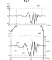
- FIG. 4 is a diagram showing an example of swing data SwD.
- FIG. 5 is a flow chart showing processing executed by the data processing device 2 .
- FIG. 6 is a diagram showing swing data SwDN acquired when the object 1 is deformed by an action other than swing.
- FIG. 7 is a block diagram showing an example of the configuration of the data processing device 2a.
- FIG. 8 is a flow chart showing processing executed by the data processing device 2a.
- FIG. 9 is a block diagram showing an example of the configuration of the data processing device 2b.
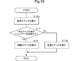
- FIG. 10 is a flow chart showing the processing executed by the data processing device 2b.
- FIG. 11 is a diagram showing Modification 1 of the determination method in the determination step.
- FIG. 12 is a diagram showing Modification 2 of the determination method in the determination step.
- FIG. 1 is a diagram showing an example of a device under test 1 to which a data processing device 2 is attached.
- FIG. 2 is a block diagram showing an example of the configuration of the data processing device 2.
- FIG. 3A and 3B are rear and left side views of the sensor 10.
- FIG. 4 is a diagram showing an example of swing data SwD.
- the vertical axis indicates signal output.
- the horizontal axis indicates time.
- the up-down direction, the left-right direction, and the front-rear direction are defined.
- the direction in which the shaft of the object 1 extends is defined as the vertical direction.
- the direction in which the face of the head of the device under test 1 faces is defined as the left direction.
- a direction orthogonal to the up-down direction and the left-right direction is defined as the front-rear direction.
- the up-down direction, the left-right direction, and the front-rear direction are directions defined for explanation. Therefore, the up-down direction, left-right direction, and front-back direction of the device under test 1 during actual use need not coincide with the up-down direction, left-right direction, and front-back direction shown in FIG.
- the object 1 to be measured is a golf club. Therefore, as shown in FIG. 1, the object to be measured 1 has a rod shape extending in the vertical direction. A user swings the device under test 1 . When the user swings, the object to be measured 1 deforms. Specifically, when the user swings the object 1 to be measured, the object to be measured 1 is deformed by an inertial force or an external force. The object 1 to be measured deforms in the left-right direction, for example, when swinging.
- the data processing device 2 is attached to the object 1 to be measured.
- the data processing device 2 includes a sensor 10, an AD converter 20, an arithmetic circuit 30 and a memory 40, as shown in FIG.
- Sensor 10 , AD converter 20 , arithmetic circuit 30 and memory 40 are attached to device under test 1 . More precisely, sensor 10 , AD converter 20 , arithmetic circuit 30 and memory 40 are fixed to device under test 1 .
- the sensor 10 detects a physical quantity related to the amount of deformation of the object 1 to be measured.
- a physical quantity related to the amount of deformation of the object 1 to be measured is a numerical value that changes according to changes in the amount of deformation of the object 1 to be measured.
- Physical quantities related to the amount of deformation of the object to be measured 1 are, for example, the amount of deformation of the object to be measured 1, the differential value of the amount of deformation of the object to be measured 1, the stress occurring in the object to be measured 1, and the like.
- the physical quantity related to the amount of deformation of the object 1 to be measured is a differential value of the amount of deformation of the object 1 to be measured.
- the differential value of the deformation amount of the object to be measured 1 will be referred to as a differential value BV.
- the sensor 10 generates an electric charge corresponding to a physical quantity related to the amount of deformation of the object 1 to be measured.
- the sensor 10 generates charges according to the differential value BV.
- the sensor 10 converts the charge into an output signal Sig1, which is a voltage signal.
- the sensor 10 continuously acquires the output signal Sig1 based on the sampling interval of the sensor 10 .
- the value of the output signal Sig1 is a value corresponding to the differential value of the lateral deformation amount of the object 1 to be measured.
- the object to be measured 1 undergoes elastic deformation.
- the differential value of the lateral deformation amount of the object 1 to be measured is proportional to the force applied to the object 1 to be measured when the user swings.
- the value of the output signal Sig1 indirectly indicates the force applied when the user swings the object 1 to be measured.
- the sensor 10 is a piezoelectric sensor that detects pressure.
- the sensor 10 includes a piezoelectric film 100, a first electrode 101F, a second electrode 101B, a charge amplifier 102 and a voltage amplifier circuit 103, as shown in FIG.
- the piezoelectric film 100 has a sheet shape. Therefore, the piezoelectric film 100 has a first main surface F1 and a second main surface F2, as shown in FIG.
- the vertical length of the piezoelectric film 100 is longer than the horizontal length of the piezoelectric film 100 .
- the piezoelectric film 100 has a rectangular shape with long sides extending in the vertical direction when viewed in the front-rear direction.
- the piezoelectric film 100 generates an electric charge corresponding to the differential value BV of the deformation amount of the piezoelectric film 100 .
- the piezoelectric film 100 is a PLA film.
- the piezoelectric film 100 will be described in more detail below.
- piezoelectric film 100 is a film formed from a chiral polymer.
- a chiral polymer is, for example, polylactic acid (PLA), particularly L-type polylactic acid (PLLA).
- PLA polylactic acid
- PLLA L-type polylactic acid
- a PLLA composed of a chiral polymer has a helical structure in its main chain.
- PLLA is uniaxially stretched and has piezoelectricity in which the molecules are oriented.
- the piezoelectric film 100 has a piezoelectric constant of d14.
- the uniaxial stretching direction (orientation direction) of the piezoelectric film 100 forms an angle of 45 degrees with respect to each of the vertical direction and the horizontal direction. This 45 degrees includes angles including, for example, about 45 degrees ⁇ 10 degrees.
- the piezoelectric film 100 generates electric charge by being deformed such that the piezoelectric film 100 is elongated in the vertical direction or deformed by being compressed in the vertical direction.
- the piezoelectric film 100 generates a positive electric charge when it is deformed, for example, by being elongated in the vertical direction.
- the piezoelectric film 100 generates a negative charge when deformed, for example, by being compressed vertically.
- the magnitude of the charge depends on the differential value BV of the vertical deformation amount of the piezoelectric film 100 due to extension or compression.
- the first electrode 101F is a signal electrode.
- the first electrode 101F is provided on the first main surface F1.
- the first electrode 101F covers the first main surface F1.
- the first electrode 101F is, for example, an organic electrode such as ITO (indium tin oxide) or ZnO (zinc oxide), a metal film by vapor deposition or plating, or a printed electrode film by silver paste.
- the second electrode 101B is a ground electrode.
- the second electrode 101B is connected to ground potential.
- the second electrode 101B is provided on the second main surface F2. Thereby, the piezoelectric film 100 is positioned between the first electrode 101F and the second electrode 101B.
- the second electrode 101B covers the second main surface F2.
- the second electrode 101B is, for example, an organic electrode such as ITO (indium tin oxide) or ZnO (zinc oxide), a metal film by vapor deposition or plating, or a printed electrode film by silver paste.
- Such a sensor 10 is fixed to the object 1 to be measured via an adhesive layer (not shown). Specifically, the adhesive layer fixes the object to be measured 1 and the first electrode 101F.
- the piezoelectric film 100 expands and contracts in the vertical direction.
- the piezoelectric film 100 generates an electric charge. That is, in this embodiment, the piezoelectric film 100 generates a negative charge when the object 1 to be measured bends to the right. Moreover, in this embodiment, when the object 1 to be measured is bent leftward, the piezoelectric film 100 generates a positive charge.
- the charge amplifier 102 converts the charge generated by the piezoelectric film 100 into an output signal Sig1, which is a voltage signal. After the conversion, charge amplifier 102 outputs output signal Sig1 to voltage amplifier circuit 103 .
- the voltage amplifier circuit 103 amplifies the output signal Sig1 and outputs it to the AD converter 20 .
- the AD converter 20 AD-converts the output signal Sig1. Thereby, the AD converter 20 converts the output signal Sig1 into a digital signal.
- the arithmetic circuit 30 performs an acquisition step of acquiring the swing data SwD, a determination step of determining whether or not deletion of the swing data SwD is necessary, a deletion step of deleting the swing data SwD when it is determined that the swing data SwD should be deleted, to run.
- the swing data SwD indicates the relationship between the physical quantity related to the amount of deformation of the object 1 and time. In this embodiment, as shown in FIG. 4, the swing data SwD indicates the relationship between the differential value BV of the deformation amount of the object 1 and the time t. More precisely, the swing data SwD indicates the relationship between the differential value BV of the lateral deformation amount of the object 1 and the time t.
- the swing data SwD includes numerical values corresponding to physical quantities related to the amount of deformation of the object 1 to be measured.
- Arithmetic circuit 30 generates swing data SwD based on output signal Sig1. More specifically, the arithmetic circuit 30 converts a portion of the output signal Sig1 output by the sensor 10 into swing data SwD. For example, as shown in FIG. 4, the sensor 10 continuously outputs the output signal Sig1. At this time, the arithmetic circuit 30 converts the portion of the output signal Sig1 that is output between time ST and time ED into swing data SwD. Time ED is a time later than time ST.
- the arithmetic circuit 30 generates the swing data SwD indicating the relationship between the differential value BV and the time t from the time ST to the time ED. That is, in the present embodiment, the arithmetic circuit 30 acquires the swing data SwD by generating the swing data SwD based on the output signal Sig1. After the arithmetic circuit 30 generates the swing data SwD, the determination step is executed.
- FIG. 5 is a flow chart showing processing executed by the data processing device 2 .
- FIG. 6 is a diagram showing swing data SwDN acquired when the object 1 is deformed by an action other than swing. Specifically, the swing data SwDN in FIG. 6 indicates the deformation of the object 1 when the user knocks the object 1 down.
- the vertical axis indicates signal output.
- the horizontal axis indicates time.
- the processing in the arithmetic circuit 30 is started when the power of the data processing device 2 is turned on (Fig. 5: START). After the start, the arithmetic circuit 30 performs an acquisition step of acquiring swing data SwD (see the lower graph in FIG. 4) showing the relationship between the differential value BV (physical quantity related to the amount of deformation of the object 1) and the time t. (FIG. 5: step S10). Since the details of the acquisition step have already been explained, further explanation is omitted.
- the arithmetic circuit 30 determines whether or not the swing data SwD indicates the differential value BV (physical quantity related to the amount of deformation of the object 1 to be measured) generated when the object 1 to be measured is swung.
- a judgment step for judging necessity of deletion of the swing data SwD is executed ( FIG. 5 : step S11).
- the device under test 1 is greatly deformed. In this case, the amount of deformation of the object to be measured 1 is large. Therefore, the magnitude of the differential value BV is large.
- the user deforms the object 1 by an action other than swinging the object 1 is not significantly deformed. In this case, the amount of deformation of the object 1 to be measured is small.
- the magnitude of the differential value BV is small.
- the arithmetic circuit 30 can determine whether or not the swing data SwD indicates the differential value BV that occurs when the device under test 1 is swung. .
- the arithmetic circuit 30 determines whether or not the maximum value of the first difference value DV1 in the swing data SwD is greater than or equal to the first determination value 1stTh.
- the first difference value DV1 becomes the maximum value at time TT. Therefore, it is determined whether or not the value of the first difference value DV1 at the time TT is greater than or equal to the first determination value 1stTh.
- differential value BV is "0.2".
- the reference value SiV is "2.0". In this case, the value obtained by subtracting the reference value SiV from the differential value BV is "-1.8". Therefore, the arithmetic circuit 30 calculates the first difference value DV1 as "1.8".
- the arithmetic circuit 30 determines whether the first difference value DV1 is equal to or greater than the first determination value 1stTh. Then, when the first difference value DV1 is equal to or greater than the first determination value and equal to or greater than 1stTh, the arithmetic circuit 30 determines not to delete the swing data SwD. In the example shown in FIG. 4, the first difference value DV1 is "1.8" and the first determination value 1stTh is "1.8" at the time TT. In this case, the first difference value DV1 is greater than or equal to the first determination value 1stTh. Therefore, the arithmetic circuit 30 determines that it is unnecessary to delete the swing data SwD.
- the arithmetic circuit 30 determines to delete the swing data SwD.
- the differential value BV is greater than or equal to the first determination value and less than 1stTh. Therefore, the arithmetic circuit 30 determines that deletion of the swing data SwDN shown in FIG. 6 is necessary.
- the arithmetic circuit 30 executes a deletion step of deleting the swing data SwD. In other words, if the arithmetic circuit 30 determines in the determination step that the swing data SwD does not indicate the differential value BV that occurs when the object 1 is swung ( FIG. 5 : step S11 No), the arithmetic circuit 30 , a deletion step for deleting the swing data SwD is executed ( FIG. 5 : step S12).
- the arithmetic circuit 30 determines that deletion of the swing data SwD is unnecessary, the arithmetic circuit 30 executes a transmission step of transmitting the swing data SwD to the storage medium 50 .
- the arithmetic circuit 30 determines in the determination step that the swing data SwD indicates the differential value BV that occurs when the device under test 1 is swung ( FIG. 5 : step S11 Yes)
- the arithmetic circuit 30 A transmission step of transmitting the swing data SwD to the storage medium 50 is executed ( FIG. 5 : step S13).
- an arithmetic circuit 30 and a storage medium 50 are communicably connected.
- Arithmetic circuit 30 transmits swing data SwD to storage medium 50 .
- a server or the like has the storage medium 50 .
- the processing shown above is executed by the arithmetic circuit 30 reading out from the memory 40 a program related to the processing in the arithmetic circuit 30 .
- an arithmetic circuit 30 and a memory 40 are communicably connected.
- the memory 40 stores programs related to the acquisition step, determination step, and deletion step.
- the memory 40 includes, for example, ROM (Read Only Memory) and RAM (Random Access Memory).
- the arithmetic circuit 30 reads the program stored in the ROM to the RAM. Thereby, the arithmetic circuit 30 executes an acquisition step, a determination step, and a deletion step.
- Such an arithmetic circuit 30 is, for example, a CPU (Central Processing Unit).
- the storage capacity of the storage medium 50 is less likely to be squeezed.
- the data processing device 2 has an arithmetic circuit 30 .
- Arithmetic circuit 30 executes an acquisition step, a determination step, and a deletion step.
- the arithmetic circuit 30 acquires the swing data SwD indicating the relationship between the differential value BV (physical quantity related to the amount of deformation of the object 1) and the time t.
- the arithmetic circuit 30 determines whether or not the swing data SwD indicates the differential value BV generated when the object 1 is swung, thereby determining whether or not the swing data SwD needs to be deleted.
- the arithmetic circuit 30 executes a deletion step of deleting the swing data SwD.
- the data processing device 2 will be compared with a data processing device (hereinafter referred to as Comparative Example 1) that does not execute the obtaining step, the determining step, and the deleting step.
- the swing data may be transmitted to the storage medium regardless of whether or not the swing data needs to be deleted. For example, there is a possibility that swing data or the like acquired when the user knocks down the object to be measured is transmitted to the storage medium. As a result, there is a risk that the storage capacity of the storage medium will be squeezed.
- the data processing device 2 determines whether or not the swing data SwD indicates the differential value BV that occurs when the object 1 is swung. Then, when it is determined that the swing data SwD does not indicate the differential value BV that occurs when the device under test 1 is swung, the arithmetic circuit 30 deletes the swing data SwD. As a result, for example, the arithmetic circuit 30 does not transmit the swing data SwDN and the like shown in FIG. 6 to the storage medium 50 . Therefore, the capacity of the storage medium 50 is not squeezed by the swing data SwDN or the like. As a result, the storage capacity of the storage medium 50 is less likely to be squeezed by the data processing device 2 .
- the data processing device 2 can prevent the necessary swing data SwD from not being stored in the storage medium 50. More specifically, when it is determined that the swing data SwD indicates the differential value BV that occurs when the device under test 1 is swung, the arithmetic circuit 30 executes a transmission step of transmitting the swing data SwD to the storage medium 50. do.
- a data processing device that does not execute the transmission step hereinafter referred to as comparative example 2 and the data processing device 2 will be compared and described below. In the case of Comparative Example 2, for example, there is a possibility that the swing data will not be transmitted to the storage medium due to a user's erroneous operation or the like after the swing data is acquired.
- the necessary swing data may not be saved in the storage medium.
- the arithmetic circuit 30 transmits the swing data SwD determined not to be deleted to the storage medium 50 in the determination step. Therefore, the data processing device 2 can store the swing data SwD in the storage medium 50 without user's operation. As a result, the data processing device 2 can prevent the necessary swing data SwD from not being stored in the storage medium 50 .
- the swing data SwD includes differential values BV (numerical values corresponding to physical quantities).
- the absolute value of the difference between the reference value SiV and the differential value BV is defined as a first difference value DV1.
- the arithmetic circuit 30 determines not to delete the swing data SwD when the first difference value DV1 is greater than or equal to the first determination value 1stTh.
- the first determination value 1stTh is set based on the magnitude of the first difference value DV1 acquired when the device under test 1 is swung.
- the amount of deformation of the object under test 1 when the object under test 1 is deformed by an action other than swinging is smaller than the amount of deformation of the object under test 1 when the user swings the object under test 1 . Therefore, when the value of the first difference value DV1 in the swing data SwD is less than the first determination value 1stTh, there is a high possibility that the swing data SwD is data obtained during an action other than swing. In this case, the arithmetic circuit 30 determines to delete the swing data SwD. As a result, the data processing device 2 can more accurately determine whether or not the swing data SwD needs to be deleted.
- FIG. 7 is a block diagram showing an example of the configuration of the data processing device 2a.
- FIG. 8 is a flow chart showing processing executed by the data processing device 2a.
- the data processing device 2a differs from the data processing device 2 in the method of acquiring the swing data SwD. A detailed description will be given below.
- the same components as those of the data processing device 2 are denoted by the same reference numerals, and descriptions thereof are omitted.
- the data processing device 2a and the external processing device 60a are communicably connected.
- the external processing device 60a is a device different from the data processing device 2a.
- the external processing device 60a is a device that includes the sensor 10 in the first embodiment and a wireless communication device (not shown).
- the data processing device 2a executes an acquisition step, a determination step, and a deletion step.
- the data processing device 2a is, for example, a smart phone, a PC, or the like.
- smart phones, PCs, etc. are equipped with ROM and RAM.
- the ROM stores application programs that perform the acquisition, determination, and deletion steps.
- a smart phone, a PC, or the like executes an acquisition step, a determination step, and a deletion step by, for example, loading an application program stored in a ROM into a RAM.
- the data processing device 2a includes an arithmetic circuit 30a, a communication section 31a and a display section 32a.
- the data processing device 2a is communicably connected to an external processing device 60a different from the data processing device 2a via a communication unit 31a.
- the communication unit 31a receives an output signal Sig1 corresponding to the differential value BV (physical quantity related to the amount of deformation of the object 1) from the external processing device 60a.
- the external processing device 60a generates an output signal Sig1 corresponding to the physical quantity.
- the external processing device 60a generates the output signal Sig1, for example, similarly to the sensor 10 according to the first embodiment.
- the communication unit 31a receives the output signal Sig1 from the external processing device 60a.
- the arithmetic circuit 30a receives the output signal Sig1 from the communication unit 31a.
- the arithmetic circuit 30a acquires the swing data SwD by generating the swing data SwD based on the output signal Sig1.
- the communication unit 31a receives the output signal Sig1 corresponding to the physical quantity from the external processing device 60a different from the data processing device 2a ( FIG. 8 : step S20).
- the arithmetic circuit 30a acquires the swing data SwD by generating the swing data SwD based on the output signal Sig1 ( FIG. 8 : step S10a). For example, similarly to the data processing device 2, the arithmetic circuit 30a receives an output signal Sig1 output from the external processing device 60a between time ST and time ED. Thereby, the arithmetic circuit 30a obtains the swing data SwD indicating the relationship between the differential value BV and the time t from the time ST to the time ED.
- the arithmetic circuit 30a executes a determination step ( FIG. 8 : step S11).
- the arithmetic circuit 30a determines to delete the swing data SwD (Fig. 8: step S11 Yes)
- the arithmetic circuit 30a executes a deletion step (Fig. 8: step S12).
- the arithmetic circuit 30a determines not to delete the swing data SwD (Fig. 8: step S11 No)
- the arithmetic circuit 30a executes the transmission step (Fig. 8: step S13).
- the data processing device 2a transmits the swing data SwD to the storage medium 50 via the communication section 31a.
- a server or the like (not shown) has the storage medium 50 .
- the display unit 32a performs display based on the execution result of the deletion step.
- the display unit 32a displays, for example, whether or not the swing data SwD has been deleted.
- the display unit 32a displays a text message such as "The swing data SwD has been deleted.”
- the display unit 32a displays a text message such as "The swing data SwD has been saved.”
- the data processing device 2a includes a communication section 31a.
- the communication unit 31a receives an output signal Sig1 corresponding to a physical quantity from an external processing device 60a different from the data processing device 2a.
- the arithmetic circuit 30a acquires the swing data SwD by generating the swing data SwD based on the output signal Sig1.
- the arithmetic circuit 30a executes the determination step. In this case, for the same reason as the data processing device 2, the storage capacity of the storage medium 50 of the data processing device 2a is less likely to be squeezed.
- the data processing device 2a it is possible to provide a user-friendly data processing device 2a. More specifically, the data processing device 2a has a display section 32a. The display unit 32a performs display based on the execution result of the deletion step. If the data processing device 2a does not include the display unit 32a, the user is not notified whether or not the swing data SwD has been deleted. Therefore, the user does not know whether or not the swing data SwD has been deleted. This can confuse users. However, when the data processing device 2a includes the display unit 32a, the display unit 32a notifies the user whether or not the swing data SwD has been deleted. This allows the user to know whether or not the swing data SwD has been deleted. Therefore, the user is less likely to be confused. That is, it is possible to provide the data processing device 2a that is easy for the user to use.
- FIG. 9 is a block diagram showing an example of the configuration of the data processing device 2b.
- FIG. 10 is a flow chart showing the processing executed by the data processing device 2b.
- the data processing device 2b differs from the data processing device 2 in the method of acquiring the swing data SwD. A detailed description will be given below.
- the same components as those of the data processing device 2 are denoted by the same reference numerals, and descriptions thereof are omitted.
- the data processing device 2b and the external processing device 60b are communicably connected.
- the external processing device 60b is a device different from the data processing device 2a.
- the external processing device 60b is, for example, a smart phone, a PC, or the like.
- the data processing device 2b is, for example, a server or the like. Then, in this embodiment, the data processing device 2b executes an acquisition step, a determination step, and a deletion step. A detailed description will be given below.
- the data processing device 2b includes an arithmetic circuit 30b, a communication section 31b, and a storage medium 50b.
- the data processing device 2b is connected to an external processing device 60b different from the data processing device 2b via a communication section 31b.
- the communication unit 31b receives the swing data SwD from the external processing device 60b.
- the external processing device 60b generates the swing data SwD, for example, similarly to the data processing device 2a according to the second embodiment.
- the communication unit 31b receives the generated swing data SwD. That is, in the present embodiment, the communication unit 31b acquires the swing data SwD by receiving the swing data SwD from the external processing device 60b different from the data processing device 2b.
- the communication unit 31b acquires the swing data SwD by receiving the swing data SwD from the external processing device 60b different from the data processing device 2b ( FIG. 10 : step S10b).
- the arithmetic circuit 30b After receiving the swing data SwD, the arithmetic circuit 30b executes the determination step (FIG. 10: step S11).
- the arithmetic circuit 30b determines to delete the swing data SwD (Fig. 10: step S11 Yes)
- the arithmetic circuit 30b executes a deletion step (Fig. 10: step S12).
- the arithmetic circuit 30b determines not to delete the swing data SwD (Fig. 10: step S11 No), the arithmetic circuit 30b further executes a transmission step of transmitting the swing data SwD to the storage medium 50b (Fig. 10: step S13b). ).
- the storage capacity of the storage medium 50b is less likely to be squeezed.
- the data processing device 2b includes a communication section 31b.
- the communication unit 31b acquires the swing data SwD by receiving the swing data SwD from the external processing device 60b different from the data processing device 2b.
- the arithmetic circuit 30b executes the determination step after receiving the swing data SwD.
- the storage capacity of the storage medium 50b of the data processing device 2b is less likely to be squeezed for the same reason as the data processing device 2b.
- the data processing device 2b can prevent the necessary swing data SwD from not being stored in the storage medium 50b.
- the data processor 2b includes a storage medium 50b.
- the arithmetic circuit 30b determines not to delete the swing data SwD, the arithmetic circuit 30b executes a transmission step of transmitting the swing data SwD to the storage medium 50b. In this case, for the same reason as the data processing device 2, the data processing device 2b can prevent the necessary swing data SwD from being stored in the storage medium 50b.
- FIG. 11 is a diagram showing Modification 1 of the determination method in the determination step.
- a data processing device 2c (not shown) according to Modification 1 includes an arithmetic circuit 30c (not shown). The structure of the data processing device 2c will be described with reference to FIG.
- the arithmetic circuit 30c determines whether it is necessary to delete the swing data SwD by detecting the number of times the first difference value DV1 exceeds the second determination value 2ndTh in the determination step.
- the data processing device 2c stores the second determination value 2ndTh.
- the processing of the arithmetic circuit 30c will be described in detail below.
- the arithmetic circuit 30c acquires the swing data SwD.
- the swing data SwD includes numerical values corresponding to physical quantities.
- the swing data SwD includes the differential value BV (see FIG. 11).
- the absolute value of the difference between the reference value SiV and the differential value BV (numerical value corresponding to the physical quantity) is defined as a first difference value DV1.
- the arithmetic circuit 30c executes a counting step of counting the number of times the first difference value DV1 becomes equal to or greater than the second determination value 2ndTh. For example, in the example shown in FIG.
- the number of times that the first difference value DV1 is greater than or equal to the second determination value 2ndTh is seven times.
- the arithmetic circuit 30c counts the number of times that the first difference value DV1 becomes equal to or greater than the second determination value 2ndTh as seven times. Then, when the number of times exceeds the reference number, the arithmetic circuit 30c determines not to delete the swing data SwD.
- the reference number is set in the data processing device 2c. For example, in the example shown in FIG. 11, the reference number is set to "5" for the data processing device 2c. In this case, the data processing device 2c determines whether or not the number of times the first difference value DV1 becomes equal to or greater than the second determination value 2ndTh is 5 or more.
- the reference number is set to "10" in the data processing device 2c
- FIG. 12 is a diagram showing Modification 2 of the determination method in the determination step.
- a data processing device 2d (not shown) according to Modification 2 includes an arithmetic circuit 30d (not shown). The structure of the data processing device 2d will be described with reference to FIG.
- the arithmetic circuit 30d identifies one or more numerical peaks in the swing data SwD. Then, based on the numerical peak, it is determined whether the swing data SwD needs to be deleted. A detailed description will be given below.
- the arithmetic circuit 30d acquires the swing data SwD.
- the swing data SwD includes numerical values corresponding to physical quantities.
- the swing data SwD includes the differential value BV (see FIG. 12).
- the absolute value of the difference between the reference value SiV and the differential value BV (numerical value corresponding to the physical quantity) is defined as a first difference value DV1.
- the arithmetic circuit 30d specifies one or more numerical peaks Pe in the swing data SwD when the first difference value DV1 is greater than or equal to the third determination value 3rdTh. For example, in the example shown in FIG. 12, at time TT, the first difference value DV1 is greater than or equal to the third determination value 3rdTh.
- the arithmetic circuit 30d specifies numerical peaks Pe1, P2, Pe3, Pe4, and Pe5, for example, as shown in FIG. Then, the arithmetic circuit 30d executes the determination step based on the differential value BV at the time TT when the first difference value DV1 becomes equal to or greater than the third determination value 3rdTh and the numerical value at the peak Pe. For example, the arithmetic circuit 30d calculates the absolute value of the difference between the differential value BV and the value of the peak Pe.
- the arithmetic circuit 30d determines to delete the swing data SwD. .
- a data processing device 2d can more accurately determine whether or not it is necessary to delete the swing data SwD.
- the data processors 2, 2a, 2b, 2c, and 2d according to the present invention are not limited to the data processors 2, 2a, 2b, 2c, and 2d, and can be modified within the scope of the gist thereof.
- the configurations of the data processing devices 2, 2a, 2b, 2c, and 2d may be combined arbitrarily.
- the arithmetic circuits 30, 30a, 30b, 30c, 30d, and 30e may execute the determination step based on machine learning or artificial intelligence.
- the arithmetic circuits 30, 30a, 30b, 30c, 30d, and 30e learn swing data SwD obtained when the object 1 is swung as teacher data, for example.
- the arithmetic circuits 30, 30a, 30b, 30c, 30d, and 30e can determine whether or not the swing data SwD needs to be deleted by pattern recognition based on the teacher data, for example.
- the data processing devices 2, 2a, and 2b store a learned model that indicates the relationship between the feature amount included in the swing data SwD and the user's motion when the swing data SwD is obtained.
- Arithmetic circuits 30, 30a, 30b, 30c, 30d, and 30e input swing data SwD to the learned model.
- the trained model outputs a result as to whether or not to delete the swing data SwD.
- the arithmetic circuits 30, 30a, 30b, 30c, 30d, and 30e correct the learned model based on the output results.
- the arithmetic circuits 30, 30a, 30b, 30c, 30d, and 30e can improve the accuracy of data deletion necessity determination in the arithmetic circuits 30, 30a, 30b, 30c, 30d, and 30e.
- the object 1 to be measured does not necessarily have to be a golf club.
- the object to be measured 1 may be a rod-shaped member such as a baseball bat, tennis racket, badminton racket, or the like.
- the object under test 1 may include at least one of a golf club, a bat, and a racket.
- bats and rackets are objects to be measured 1 that are easily deformed during a swing. That is, when the object 1 to be measured is a bat or a racket, the data processors 2, 2a, 2b, 2c, and 2d easily detect the deformation of the object 1 when the user swings.
- the data processing device 2 executes the determination step based on the first difference value DV1.
- the first difference value DV1 is the absolute value of the difference from the numerical value corresponding to the physical quantity. That is, the data processor 2 can execute the determination step even when the waveform of the output signal Sig1 is inverted with respect to the reference value SiV. Therefore, the data processing device 2 can determine whether or not to delete the swing data SwD even when the user reverses the object 1 for each swing. For example, if the object to be measured 1 is a bat, a racket, or the like, the user may invert the object to be measured 1 for each swing. Also in this case, the data processing device 2 can accurately determine whether or not the swing data SwD needs to be deleted for each swing. Similarly, the data processing device 2 can accurately determine whether or not to delete the swing data SwD even when the user changes the direction in which the object 1 is swung for each swing.
- the object 1 to be measured is a golf club.
- the swing data SwD does not necessarily have to be obtained when the golf club hits the golf ball.
- the data processors 2, 2a, 2b, 2c, and 2d are capable of determining whether the object to be measured 1 hits an impacting object or not to an impacting object. It is possible to use Therefore, even when the device under test 1 is a game controller or the like, it is possible to use the data processing devices 2, 2a, 2b, 2c, and 2d to determine whether data deletion is necessary.
- the data processing device 2 does not necessarily have to include the AD converter 20 . In other words, the data processing device 2 does not necessarily have to input the signal AD-converted by the AD converter 20 .
- the deformation direction of the object 1 to be measured is not limited to the vertical direction only.
- the object to be measured 1 may be deformed in a rotational direction around the center of the object to be measured 1 when viewed in the vertical direction. That is, the object 1 to be measured may be twisted in the direction of rotation.
- the sensor 10 may detect twist in the rotational direction.
- the physical quantity may include other than the amount of deformation of the object 1 to be measured, the differential value of the amount of deformation of the object 1 to be measured, and the stress occurring in the object 1 to be measured.
- the sensor 10 may be a strain gauge.
- the physical quantity measured by the sensor 10 is the amount of deformation of the object 1 to be measured.
- the physical quantity does not necessarily have to be the differential value BV of the deformation amount of the object 1 to be measured.
- the arithmetic circuit 30 may perform the determination step based on the differential value of the vertical deformation amount of the piezoelectric film 100 .
- the physical quantity includes a differential value of the vertical deformation amount of the piezoelectric film 100 .
- the reference number may be a value other than "5" or "10".
- the arithmetic circuits 30, 30a, 30b, 30c, 30d, and 30e do not necessarily have to be CPUs.
- the arithmetic circuits 30, 30a, 30b, 30c, 30d, and 30e may be, for example, MPUs (Micro Processing Units).
- the memory 40 does not necessarily have to include a ROM.
- the memory 40 may include, for example, flash memory instead of ROM.
- the data processing device 2 does not necessarily have to include the AD converter 20 .
- the AD converter 20 and the arithmetic circuit 30 do not necessarily have to be attached to the device under test 1 as long as the sensor 10 and the arithmetic circuit 30 are communicably connected.
- the method by which the arithmetic circuit 30 acquires the swing data SwD is, for example, the method described below.
- the data processing device 2 includes a button (hereinafter referred to as button X) not shown.
- button X When button X is pressed by the user, arithmetic circuit 30 starts receiving output signal Sig1 from sensor 10 .
- the user presses button X at time ST.
- the arithmetic circuit 30 starts receiving the output signal Sig1 from time ST.
- the arithmetic circuit 30 stops receiving the output signal Sig1.
- arithmetic circuit 30 finishes receiving output signal Sig1 at time ED.
- the arithmetic circuit 30 acquires the output signal Sig1 received between time ST and time ED as swing data SwD.
- the external processing device 60a may acquire the swing data SwD using the button X.
- the arithmetic circuit 30 may acquire the swing data SwD by setting a trigger. For example, when the first difference value DV1 is equal to or greater than the first determination value 1stTh, the differential value BV at times before and after the time when the first difference value DV1 becomes equal to or greater than the first determination value 1stTh may be acquired. .
- the arithmetic circuit 30 may acquire the output signal Sig1 between the time five seconds before the time TT and the time five seconds after the time TT as the swing data SwD. good.
- the external processing device 60a may acquire swing data SwD by setting a trigger.
- the value of the output signal Sig1 and the value of the swing data SwD do not necessarily have to match.
- the output signal Sig1 may be output as a voltage value
- the swing data SwD may be output as a binary value.
- the data processing device 2 and the storage medium 50 may be connected by wireless such as Bluetooth (registered trademark) or Wi-Fi (registered trademark). Note that the data processing device 2 and the storage medium 50 may be connected by a wire.
- the communication unit 31a and the external processing device 60a may be connected by wireless such as Bluetooth (registered trademark) or Wi-Fi (registered trademark). Note that the communication unit 31a and the external processing device 60a may be connected by a wire. Similarly, the communication unit 31a and the storage medium 50 may be connected wirelessly or by wire.
- the communication unit 31b and the external processing device 60b may be connected by wireless such as Bluetooth (registered trademark) or Wi-Fi (registered trademark). Note that the communication unit 31b and the external processing device 60b may be connected by a wire.
- the display unit 32a may indicate whether or not the deletion step has been executed by a method other than displaying a text message.
- the display unit 32a may indicate whether or not the deletion step has been performed, for example by displaying an image.
- the storage media 50, 50b are, for example, SSDs (Solid State Drives) and HDDs (Hard Disk Drives).
Landscapes
- Engineering & Computer Science (AREA)
- Theoretical Computer Science (AREA)
- Health & Medical Sciences (AREA)
- General Health & Medical Sciences (AREA)
- Physical Education & Sports Medicine (AREA)
- Physics & Mathematics (AREA)
- General Engineering & Computer Science (AREA)
- General Physics & Mathematics (AREA)
- Measurement Of The Respiration, Hearing Ability, Form, And Blood Characteristics Of Living Organisms (AREA)
- Recording Measured Values (AREA)
Priority Applications (2)
| Application Number | Priority Date | Filing Date | Title |
|---|---|---|---|
| JP2023535181A JP7473086B2 (ja) | 2021-07-15 | 2022-06-10 | データ処理装置及びプログラム |
| US18/410,167 US20240143284A1 (en) | 2021-07-15 | 2024-01-11 | Data processing apparatus and program |
Applications Claiming Priority (2)
| Application Number | Priority Date | Filing Date | Title |
|---|---|---|---|
| JP2021116951 | 2021-07-15 | ||
| JP2021-116951 | 2021-07-15 |
Related Child Applications (1)
| Application Number | Title | Priority Date | Filing Date |
|---|---|---|---|
| US18/410,167 Continuation US20240143284A1 (en) | 2021-07-15 | 2024-01-11 | Data processing apparatus and program |
Publications (1)
| Publication Number | Publication Date |
|---|---|
| WO2023286502A1 true WO2023286502A1 (ja) | 2023-01-19 |
Family
ID=84919232
Family Applications (1)
| Application Number | Title | Priority Date | Filing Date |
|---|---|---|---|
| PCT/JP2022/023398 Ceased WO2023286502A1 (ja) | 2021-07-15 | 2022-06-10 | データ処理装置及びプログラム |
Country Status (3)
| Country | Link |
|---|---|
| US (1) | US20240143284A1 (https=) |
| JP (1) | JP7473086B2 (https=) |
| WO (1) | WO2023286502A1 (https=) |
Families Citing this family (1)
| Publication number | Priority date | Publication date | Assignee | Title |
|---|---|---|---|---|
| WO2022239433A1 (ja) * | 2021-05-11 | 2022-11-17 | 株式会社村田製作所 | センサユニット |
Citations (4)
| Publication number | Priority date | Publication date | Assignee | Title |
|---|---|---|---|---|
| JPH09154996A (ja) * | 1995-12-06 | 1997-06-17 | Tokico Ltd | スイング分析装置 |
| US5792000A (en) * | 1996-07-25 | 1998-08-11 | Sci Golf Inc. | Golf swing analysis method and apparatus |
| JP2015178026A (ja) * | 2015-06-11 | 2015-10-08 | セイコーエプソン株式会社 | スイング分析装置、スイング分析システム、スイング分析方法、スイング分析プログラム、および記録媒体 |
| JP2016168196A (ja) * | 2015-03-13 | 2016-09-23 | ヤマハ株式会社 | スイング計測システム |
-
2022
- 2022-06-10 WO PCT/JP2022/023398 patent/WO2023286502A1/ja not_active Ceased
- 2022-06-10 JP JP2023535181A patent/JP7473086B2/ja active Active
-
2024
- 2024-01-11 US US18/410,167 patent/US20240143284A1/en active Pending
Patent Citations (4)
| Publication number | Priority date | Publication date | Assignee | Title |
|---|---|---|---|---|
| JPH09154996A (ja) * | 1995-12-06 | 1997-06-17 | Tokico Ltd | スイング分析装置 |
| US5792000A (en) * | 1996-07-25 | 1998-08-11 | Sci Golf Inc. | Golf swing analysis method and apparatus |
| JP2016168196A (ja) * | 2015-03-13 | 2016-09-23 | ヤマハ株式会社 | スイング計測システム |
| JP2015178026A (ja) * | 2015-06-11 | 2015-10-08 | セイコーエプソン株式会社 | スイング分析装置、スイング分析システム、スイング分析方法、スイング分析プログラム、および記録媒体 |
Also Published As
| Publication number | Publication date |
|---|---|
| JPWO2023286502A1 (https=) | 2023-01-19 |
| JP7473086B2 (ja) | 2024-04-23 |
| US20240143284A1 (en) | 2024-05-02 |
Similar Documents
| Publication | Publication Date | Title |
|---|---|---|
| US20140100050A1 (en) | Golf swing analyzing apparatus and method of analyzing golf swing | |
| CN102553194B (zh) | 摆动分析装置 | |
| US20150111657A1 (en) | Movement analysis method, movement analysis apparatus, and movement analysis program | |
| US11173362B2 (en) | Analysis apparatus, analysis method, and recording medium | |
| JP5773144B2 (ja) | 運動解析装置、運動解析システム、運動解析プログラム、および、記録媒体 | |
| JP2015013008A (ja) | 運動検出装置および運動検出プログラム並びに運動解析システム | |
| JP2012130414A (ja) | スイング分析装置 | |
| CN104645585A (zh) | 运动分析方法以及运动分析装置 | |
| JP5773122B2 (ja) | スイング分析装置及びスイング分析プログラム | |
| JP2016067410A (ja) | 運動解析装置、運動解析システム、運動解析方法及びプログラム | |
| US20240091620A1 (en) | Processing device | |
| WO2023286502A1 (ja) | データ処理装置及びプログラム | |
| WO2015141183A1 (ja) | 運動解析装置、運動解析システム、運動解析方法、運動解析情報の表示方法及びプログラム | |
| JP2015073821A (ja) | 運動解析方法、運動解析装置、および運動解析プログラム | |
| JP2018171244A (ja) | ゴルフクラブシャフトフィッティングシステム、情報処理装置及び方法 | |
| JP7448096B2 (ja) | センサユニット | |
| CN104645595A (zh) | 运动分析方法、运动分析装置 | |
| JP2015084952A (ja) | 運動具挙動解析装置、運動具挙動解析方法および運動具挙動解析プログラム | |
| US20170203177A1 (en) | Intelligent striking practice system | |
| JP6268897B2 (ja) | 運動解析方法、運動解析プログラム、および運動解析装置 | |
| US20250013794A1 (en) | Arithmetic circuit and arithmetic program | |
| TWI541050B (zh) | 矯正打擊姿勢之裝置及方法 | |
| JP6665836B2 (ja) | ゴルフクラブフィッティングシステム、情報処理装置及び方法 | |
| JP2016209122A (ja) | 打撃解析装置、打撃解析システム、打撃解析方法、及びプログラム | |
| WO2026004391A1 (ja) | ゴルフスイングの判定装置、判定方法および判定プログラム |
Legal Events
| Date | Code | Title | Description |
|---|---|---|---|
| 121 | Ep: the epo has been informed by wipo that ep was designated in this application |
Ref document number: 22841846 Country of ref document: EP Kind code of ref document: A1 |
|
| WWE | Wipo information: entry into national phase |
Ref document number: 2023535181 Country of ref document: JP |
|
| NENP | Non-entry into the national phase |
Ref country code: DE |
|
| 122 | Ep: pct application non-entry in european phase |
Ref document number: 22841846 Country of ref document: EP Kind code of ref document: A1 |