WO2023286189A1 - 電力変換装置 - Google Patents
電力変換装置 Download PDFInfo
- Publication number
- WO2023286189A1 WO2023286189A1 PCT/JP2021/026406 JP2021026406W WO2023286189A1 WO 2023286189 A1 WO2023286189 A1 WO 2023286189A1 JP 2021026406 W JP2021026406 W JP 2021026406W WO 2023286189 A1 WO2023286189 A1 WO 2023286189A1
- Authority
- WO
- WIPO (PCT)
- Prior art keywords
- unit
- power conversion
- signal
- relay
- relay unit
- Prior art date
- Legal status (The legal status is an assumption and is not a legal conclusion. Google has not performed a legal analysis and makes no representation as to the accuracy of the status listed.)
- Ceased
Links
Images






Classifications
-
- H—ELECTRICITY
- H02—GENERATION; CONVERSION OR DISTRIBUTION OF ELECTRIC POWER
- H02M—APPARATUS FOR CONVERSION BETWEEN AC AND AC, BETWEEN AC AND DC, OR BETWEEN DC AND DC, AND FOR USE WITH MAINS OR SIMILAR POWER SUPPLY SYSTEMS; CONVERSION OF DC OR AC INPUT POWER INTO SURGE OUTPUT POWER; CONTROL OR REGULATION THEREOF
- H02M7/00—Conversion of AC power input into DC power output; Conversion of DC power input into AC power output
- H02M7/42—Conversion of DC power input into AC power output without possibility of reversal
- H02M7/44—Conversion of DC power input into AC power output without possibility of reversal by static converters
- H02M7/48—Conversion of DC power input into AC power output without possibility of reversal by static converters using discharge tubes with control electrode or semiconductor devices with control electrode
-
- H—ELECTRICITY
- H02—GENERATION; CONVERSION OR DISTRIBUTION OF ELECTRIC POWER
- H02M—APPARATUS FOR CONVERSION BETWEEN AC AND AC, BETWEEN AC AND DC, OR BETWEEN DC AND DC, AND FOR USE WITH MAINS OR SIMILAR POWER SUPPLY SYSTEMS; CONVERSION OF DC OR AC INPUT POWER INTO SURGE OUTPUT POWER; CONTROL OR REGULATION THEREOF
- H02M1/00—Details of apparatus for conversion
- H02M1/0003—Details of control, feedback or regulation circuits
-
- H—ELECTRICITY
- H02—GENERATION; CONVERSION OR DISTRIBUTION OF ELECTRIC POWER
- H02M—APPARATUS FOR CONVERSION BETWEEN AC AND AC, BETWEEN AC AND DC, OR BETWEEN DC AND DC, AND FOR USE WITH MAINS OR SIMILAR POWER SUPPLY SYSTEMS; CONVERSION OF DC OR AC INPUT POWER INTO SURGE OUTPUT POWER; CONTROL OR REGULATION THEREOF
- H02M1/00—Details of apparatus for conversion
- H02M1/32—Means for protecting converters other than automatic disconnection
-
- H—ELECTRICITY
- H02—GENERATION; CONVERSION OR DISTRIBUTION OF ELECTRIC POWER
- H02M—APPARATUS FOR CONVERSION BETWEEN AC AND AC, BETWEEN AC AND DC, OR BETWEEN DC AND DC, AND FOR USE WITH MAINS OR SIMILAR POWER SUPPLY SYSTEMS; CONVERSION OF DC OR AC INPUT POWER INTO SURGE OUTPUT POWER; CONTROL OR REGULATION THEREOF
- H02M1/00—Details of apparatus for conversion
- H02M1/32—Means for protecting converters other than automatic disconnection
- H02M1/325—Means for protecting converters other than automatic disconnection with means for allowing continuous operation despite a fault, i.e. fault tolerant converters
-
- H—ELECTRICITY
- H02—GENERATION; CONVERSION OR DISTRIBUTION OF ELECTRIC POWER
- H02M—APPARATUS FOR CONVERSION BETWEEN AC AND AC, BETWEEN AC AND DC, OR BETWEEN DC AND DC, AND FOR USE WITH MAINS OR SIMILAR POWER SUPPLY SYSTEMS; CONVERSION OF DC OR AC INPUT POWER INTO SURGE OUTPUT POWER; CONTROL OR REGULATION THEREOF
- H02M1/00—Details of apparatus for conversion
- H02M1/36—Means for starting or stopping converters
Definitions
- An embodiment of the present invention relates to a power converter.
- Some power converters increase availability by redundantly configuring a plurality of power conversion units (main circuits) each having a switching element.
- Functional safety controls reduce risks that may arise during system operation. For example, by applying functional safety control to the power converter, power output from the power converter can be stopped according to the risk that has occurred, and operation in an unstable state can be restricted. Since the configuration and scale of the power conversion device are determined by the specifications required by the user, the power conversion device is required to be compatible with various configurations and scales. The more complicated the configuration and the larger the scale, the more complicated the configuration for functional safety control of multiple power conversion units, and the more difficult it was to collect information indicating the state of functional safety control. .
- the problem to be solved by the present invention is to provide a power converter that can collect information indicating the state of functional safety control of a plurality of redundant power converter units with a simple configuration.
- a power conversion apparatus is configured such that a plurality of power conversion units are divided into a plurality of banks, and the operating states of the power conversion units are controlled for each bank.
- the power converter includes a first relay unit, one or more second relay units, and a safety control section.
- the first relay unit transmits a response signal from the first power conversion unit and a response signal from a downstream side of the first relay unit to an upstream bank in a first bank associated with the first power conversion unit. send to the side
- the one or more second relay units in one or more second banks respectively associated with the one or more second power conversion units, select one of the one or more second power conversion units.
- a response signal from the second power conversion unit and a response signal from the downstream side of the one second relay unit are sent to the upstream side of the one second relay unit.
- the safety control unit is arranged upstream of the first relay unit, and sends a command signal including a control command for functional safety control to the first relay unit, thereby performing functional safety control of the first power conversion unit. and the functional safety control of the one or more second power conversion units to determine the functional safety control state of the first power conversion unit and the functional safety control state of the one or more second power conversion units.
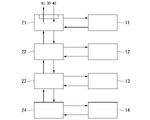
- FIG. 2 is a configuration diagram of a relay unit group in the power converter of the embodiment;
- FIG. 2 is a configuration diagram of a relay unit group in the power converter of the embodiment;
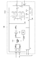
- FIG. 2 is a configuration diagram of a relay unit according to the embodiment;
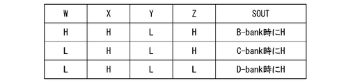
- FIG. 4 is a diagram for explaining bank selection according to the embodiment;
- FIG. 4 is a diagram for explaining bank selection according to the embodiment;
- the safety control unit monitors the functional safety control state (referred to as the safety control state) of the power conversion unit to be monitored.
- the side of the safety control unit is called the upstream side, and the side away from the safety control unit is called the downstream side.
- the power converter 1 exemplified in the embodiment has a redundant main circuit so that it can be applied to systems with relatively high requirements for availability.
- Standby redundancy means that in the power conversion device 1 having a configuration including a plurality of banks, when the power conversion unit 10 of a specific bank that has been used as the current system fails, the power conversion unit 10 of the bank that has been used as the standby system is used as the current system. system and continue the operation of the power converter 1 .
- a configuration in which one bank is used as a standby system is exemplified.
- Capacity redundancy is a configuration in which the suppliable capacity has a margin against the required capacity of AC power, and the operation is continued with the configuration that remains even if the faulty part is isolated to secure the necessary capacity. The method.
- FIG. 1A is a schematic configuration diagram of a power conversion device 1 according to an embodiment.
- FIG. 1B is a schematic configuration diagram relating to safety control of the power conversion device 1 of the embodiment.
- the power conversion device 1 shown in FIG. 1A includes, for example, power conversion units 11 to 14, a relay unit group 20, a non-safety control unit 30 (non-safety control section), and a safety control unit 40 (safety control section). Prepare.
- the power conversion units 11 to 14 each include, for example, one or more switching elements (not shown), and convert power by switching.
- the types of switching elements may be IGBTs (Insulated Gate Bipolar Transistors), IEGTs (Injection Enhanced Gate Transistors), MOSFETs (metal-oxide-semiconductor field-effect transistors), and the like.
- the power conversion unit 11 is an example of a first power conversion unit.
- Power conversion units 12 to 14 are examples of one or more second power conversion units.
- the power conversion units 11 to 14 which are examples of a plurality of power conversion units, are collectively indicated without distinction, they may simply be referred to as the power conversion unit 10 .
- the power conversion unit 10 functions as an inverter that generates AC power under control, and causes a current to flow through the windings of the motor M connected to its output.
- Each power conversion unit 10 is divided into a plurality of banks.
- the power conversion device 1 controls the operating state of each power conversion unit 10 on a bank-by-bank basis.
- the power electronics device 1 switches redundant control on a bank-by-bank basis.
- the number of banks in the power electronics device 1 can be selected from one to four, for example.
- the number of banks is determined by the required specifications of the power converter 1 . In the following description, a case where the maximum number of banks in the bank configuration in the embodiment is four will be exemplified.
- the relay unit group 20 is configured by being divided into each other according to the bank configuration, and includes relay units 21 to 24, for example.
- the relay unit 21 is associated with the first bank together with the power conversion unit 11 .
- the relay unit 22 is associated with the second bank together with the power conversion unit 12 .
- the relay unit 23 is associated with the third bank together with the power conversion unit 13 .
- the relay unit 24 is associated with the fourth bank together with the power conversion unit 14 .
- the relay unit 21 is an example of a first relay unit. Also, the relay units 22 to 24 correspond to three second relay units and are an example of one or more second relay units. Thus, the power conversion units 10 are provided downstream of the relay unit group 20, respectively. A non-safety control unit 30 and a safety control unit 40 are provided upstream of the relay unit group 20 . At least, the safety control unit 40 is arranged upstream of the relay unit group 20 . The relay unit group 20 relays control of each power conversion unit 10 from the non-safety control unit 30 and the safety control unit 40 . Relay unit group 20 relays the state of each power conversion unit 10 to non-safety control unit 30 and safety control unit 40 .
- the non-safety control unit 30 performs, for example, capacity redundancy control of each power conversion unit 10 and standby redundancy control of each power conversion unit.
- capacity redundancy control the non-safety control unit 30 performs redundant operation by adjusting the amount of power conversion in the power conversion unit 11 and the power conversion units 12 to 14 .
- standby redundant control the non-safety control unit 30 outputs use setting signals A to D corresponding to the power conversion unit 10 to be operated, thereby selecting one of the power conversion unit 11 and the power conversion units 12 to 14. Select the power conversion unit to activate.
- the selected power conversion unit 10 performs power conversion as an active system, and the power conversion unit 10 that is not selected becomes a standby system that does not perform power conversion.
- the safety control unit 40 performs functional safety control of each power conversion unit 10 to reduce risks that may occur during operation of each power conversion unit 10 .
- the safety control unit 40 generates an operation command CMD and controls the output state of each power conversion unit 10 according to the operation command CMD.
- the safety control unit 40 receives a response signal ANS from each power conversion unit 10 and monitors the operating state of functional safety control with respect to the operation command CMD.
- each power conversion unit 10 is determined by control from the non-safety control unit 30 and the safety control unit 40 .
- Switching control of switching elements provided in each power conversion unit 10 is determined by control from the non-safety control unit 30 .
- the output of each power conversion unit 10 may be limited by control from the safety control unit 40 .
- the power conversion device 1 converts a desired amount of electric power and drives the motor M by combining and functioning a plurality of redundant power conversion units 10 .
- FIG. 2A is a configuration diagram of the power conversion unit 10A of the embodiment.
- Power conversion unit 10A is an example of a three-level inverter that generates three-phase AC power.
- FIG. 2B is a configuration diagram of the power conversion unit 10B of the embodiment.
- Power conversion unit 10B is an example of a five-level inverter that generates three-phase AC power.
- Power conversion unit 10A and power conversion unit 10B are examples of power conversion unit 10 . Each of the power conversion unit 10A and the power conversion unit 10B will be described below in order.
- the power conversion unit 10A shown in FIG. 2A includes a main circuit section 111A, a main circuit control section 112, and a safety stop circuit 113, respectively.
- a main circuit section 111A for example, an interface section that electrically insulates between the main circuit section 111A and the safety stop circuit 113 and between the safety stop circuit 113 and the relay unit group 20 is appropriately provided.
- the description of the above interface section is omitted for the sake of simplicity.
- the main circuit section 111A includes NPC (Neutral-Point-Crumped) type legs each including one or a plurality of switching elements for each phase of a three-phase alternating current.
- switching of one or a plurality of switching elements is controlled by a gate pulse (gate), which will be described later.
- a gate pulse (gate) is supplied when the drive is not restricted by a safety stop circuit 113, which will be described later, and a gate pulse (gate) is supplied when the drive is restricted by the safety stop circuit 113. interrupts.
- the configuration of the main circuit section 111A shown in FIG. 2A is an example of a 3-level type, and is not limited to this, and may be a configuration other than the 3-level type, such as a 2-level type.
- the main circuit control unit 112 controls a gate pulse (s_gate) for switching one or more switching elements based on the control from the non-safety control unit 30 and the detection result of various sensors (not shown) or the estimation result of the control state. ).
- the control commands from the non-safety control unit 30 include, for example, control commands indicating reference values for position control, speed control, torque control, and the like. Note that the control command from the non-safety control unit 30 to the main circuit control section 112 may be directly supplied to the main circuit control section 112 without going through the relay unit group 20 .
- the safety stop circuit 113 is connected to the output of the main circuit control section 112 and receives a gate pulse (s_gate) from the main circuit control section 112 .
- a gate pulse s_gate
- the safety stop circuit 113 supplies a gate pulse (gate) corresponding to the gate pulse (s_gate) to the main circuit portion 111A, thereby activating the main circuit portion 111A. Let the power conversion take place. Note that the safety stop circuit 113 limits the supply of the gate pulse to the main circuit section 111A when a predetermined condition is not satisfied.
- the safety stop circuit 113 is formed so as to be connected to any one of relay units 21 to 24, which will be described later.
- the safety shutdown circuit 113 of the power conversion unit 11 receives control from the safety control unit 40 via the relay unit 21 .
- the safety stop circuit 113 receives the operation command CMD via the relay unit 21 and, in response thereto, transmits the response signal ANS to the safety control unit 40 .
- the operation command CMD and response signal ANS are denoted as CMD10 and ANS10.
- the power conversion unit 10A shown in FIG. 2A includes a main circuit section 111B instead of the main circuit section 111A of the power conversion unit 10A.
- the following description will focus on the points of difference.
- the main circuit section 111B includes two NPC (Neutral-Point-Crumped) legs each having one or more switching elements for each phase of a three-phase alternating current.
- the configuration of the main circuit section 111B shown in FIG. 2B is an example of a 5-level type, and is not limited to this.
- the output of the first leg in each phase described above is connected to the windings of the motor M, and the output of the second leg is connected to the neutral point of the AC system.
- the U phase includes legs U and legs X
- the V phase includes legs V and legs Y
- the W phase includes legs W and Z.
- Each output of leg U, leg V, and leg W is connected to each winding of the UVW phase of motor M
- each output of leg X, leg Y, and leg Z is connected to the neutral point of the AC system.
- the power conversion unit 10A and the power conversion unit 10B have different main circuit configurations, but the same control can be applied for functional safety control.
- each connection may include a reactor as described above.
- the notation of the above reactors is omitted in FIGS. 1A, 2A, 2B, and the like. It should be noted that the reactor can be omitted as shown in the above figure for a portion that does not require a reactor as described above.
- a reactor is provided, a general configuration intended for the above overcurrent protection or the like may be applied.
- Each power conversion unit 10 is controlled by a safety stop circuit 113 to stop outputting AC power when it receives an operation command CMD for "stop output" from the safety control unit 40 via the relay unit group 20. . As a result, each power conversion unit 10 stops supplying AC power. Accordingly, the supply of AC power to the windings of the motor M is stopped.
- the relay unit 21 includes a first logic processing section 210 that sends the response signal ANS from the power conversion unit 11 and the response signal ANS from the downstream side of the relay unit 21 to the upstream side.
- the relay unit 22 includes a second logic processor 220 that sends the response signal ANS from the power conversion unit 12 and the response signal ANS from the downstream side of the relay unit 22 to the upstream side.
- the relay unit 23 includes a second logic processing section 230 that sends the response signal ANS from the power conversion unit 13 and the response signal ANS from the downstream side of the relay unit 23 to the upstream side.
- the relay unit 24 includes a second logic processor 240 that sends the response signal ANS from the power conversion unit 14 and the response signal ANS from the downstream side of the relay unit 24 to the upstream side. Since a similar relay unit is not provided on the downstream side of the relay unit 24, the response signal ANS from the downstream side is not supplied to the second logic processing section 240. FIG.
- the relay units 21 to 24 are associated with each power conversion unit 10, and transmit the response signal ANS from each power conversion unit 10 and the response signal ANS from the downstream side of the relay unit. configured to be sent upstream.
- the non-safety control unit 30 generates use setting signals AD for designating each power conversion unit 10 to be operated in the power converter 1 and supplies them to the relay units 21 to 24 .
- the use setting signals AD include information for instructing the power conversion unit 10 to operate.
- the safety control unit 40 is arranged upstream of the relay unit 21 and connected to the relay unit 21 .
- the safety control unit 40 is arranged upstream of the relay units 21 to 24 .
- the safety control unit 40, the relay unit 21, and the relay units 22 to 24 are defined with the safety control unit 40 as the upstream side, and the order of connection is defined based on the order of description.
- the safety control unit 40, the relay unit 21, and the relay units 22 to 24 are electrically connected to each other according to the connection order described above.
- the safety control unit 40 monitors the functional safety control state of at least each power conversion unit 10 .
- the safety control unit 40 may send an operation command CMD to each power conversion unit 10 to control each power conversion unit 10 .
- the safety control unit 40 includes a safety stop control circuit 41 and a failure diagnosis section 42.
- the safe stop control circuit 41 sends an operation command CMD to each power conversion unit 10 and collectively controls the state of safe stop control in each power conversion unit 10 .
- the operation command CMD output by the safety stop control circuit 41 is, for example, a signal for enabling functional safety control of each power conversion unit 10 to operate them.
- a safety stop control circuit 41 and when it is enabled, outputs an H-level signal as an operation command CMD, for example.
- Each power conversion unit 10 outputs a response signal ANS10 in response to the safety control signal CMD10 in response to this operation command CMD.
- the relay units 21 to 24 relay this response signal ANS10 and notify the safety control unit 40 of it.
- the safety control unit 40 receives the response signal ANS corresponding to this response signal ANS10 as a signal indicating the safety control state of each power conversion unit 10.
- FIG. A safety control signal CMD11 to a safety control signal CMD14, which will be described later, are an example of the safety control signal CMD10.
- Response signals ANS11 to ANS14 which will be described later, are examples of the response signal ANS10.
- the failure diagnosis unit 42 determines that the functional safety control in the power converter 1 is functioning effectively. determine that there is Details of this will be described later.
- the redundantly configured power converter 1 is formed including two types of relay units regardless of the number of banks. Therefore, in the case of a configuration of three or more banks, the power converter 1 uses a plurality of relay units of the same type.
- a plurality of relay units of the same type applied to the present embodiment can be identified by hardware, without user switch operation, flag setting using software, or the like. identify in a meaningful way.
- Identification of the relay unit will be described.
- a configuration with three or more banks as described above a plurality of relay units of the same type configured with common hardware are used. In this case, it becomes necessary to identify each relay unit.
- the power conversion device 1 of the present embodiment for example, as described below, identifies relay units configured with common hardware based on their mounting positions. Configuration examples for each number of banks will be described below.
- each relay unit is one, and the same type of relay unit does not exist.
- the connection form of this configuration is schematically shown in the following formula (1).
- the first term is the first bank (referred to as A-bank), and the second term is the second bank (referred to as B-bank).
- a "+" sign indicates that it is connected. Same below.
- A-bank Unit A B-bank: Unit B connected to Unit A (2)
- A-bank Unit A B-bank: first unit B connected to unit A and second unit B C-bank: second unit B connected to first unit B (4)
- A-bank Unit A B-bank: first unit B connected to unit A and second unit B C-bank: second unit B connected to first unit B and third unit B D-bank: third unit B connected to second unit B (6)
- identification based on information on the mutual connection relationship between the relay units can identify each assigned bank.
- FIGS. 3A and 3B are configuration diagrams of the relay unit group in the power conversion device 1 of the embodiment.
- 3A and 3B show two relay unit groups in the power conversion device 1.
- FIG. The lower end of FIG. 3A and the upper end of FIG. 3B are connected.
- the connection relationship of each relay unit in the power conversion device 1 is arranged.
- the relay unit 21 has CNA1-9 as connectors for connection to the outside.
- the CNA1 has terminals ad, for example.
- CNA1 is connected to non-safety control unit 30 .
- Use setting signals AD are supplied from the non-safety control unit 30 to terminals ad of CNA1, respectively.
- the CNA 2 has terminals bh, a terminal k, and a power supply terminal pair (not shown).
- Terminals bd of CNA2 are connected to terminals bd of CNA1 in relay unit 21, respectively.
- Terminals ef of CNA2 are connected to the inputs of synthesis gate circuit 214 of relay unit 21, respectively.
- the terminal g of CNA2 is connected to the input terminal of CNA3 in relay unit 21 via a first delay circuit (DLY).
- the terminal h of CNA2 is connected to the input terminal of CNA4 in relay unit 21 via a second delay circuit (DLY).
- the terminal k of CNA1 is pulled up to a positive power supply voltage in relay unit 21 and set to H level. A predetermined DC voltage is supplied between the terminals of the power supply terminal pair (not shown) from within the relay unit 21 .
- CNA 2 is connected to CNB 1 of relay unit 22 .
- CNA3 and the output terminal of CNA4 are connected to the output of the synthesis gate circuit 214, respectively.
- CNA3 and CNA4 are connected to the safety control unit 40 respectively.
- the CNAs 5-8 are connected to the power conversion unit 11 respectively.
- CNAs 5 and 7 send a safety control signal CMD11 to power conversion unit 11 .
- CNAs 5, 7 include, for example, electrical-to-optical converters.
- CNAs 6 and 8 receive response signal ANS11 from power conversion unit 11 to safety control signal CMD11.
- CNAs 5, 7 include, for example, optical-to-electrical converters.
- the CNAs 5-8 may be connectors for optical signal transmission.
- the relay unit 22 has CNBs 1-2 and 5-8 as connectors for connection to the outside.
- CNB1 has a terminal bh, a terminal kl, and a power supply terminal pair (not shown).
- CNB 1 is connected to CNA 2 of relay unit 21 .
- Terminals bk of CNB1 are connected to terminals bk of CNA2, respectively.
- a use setting signal BD is supplied from the non-safety control unit 30 through the relay unit 21 to the terminal bd of the CNB1.
- Terminals ef of CNB1 are connected to the outputs of synthesis gate circuit 224 of relay unit 22, respectively.
- Terminals gh of CNB1 are connected to terminals gh of CNB2 within relay unit 22 .
- Terminal k of CNB1 is connected to the input of selector 221 of relay unit 22 .
- the terminal 1 of CNB1 is connected to the terminal 1 of CNA2 of relay unit 21, is supplied with a positive power supply voltage within relay unit 22, and is set to H level.
- a circuit (225) that supplies a positive power supply voltage to terminal l of CNB1 is a first voltage setting circuit (first voltage setting circuit) that outputs a first signal of H level from relay unit 22 to relay unit 21 on the upstream side. circuit 225).
- the CNB 2 includes a terminal bh, a terminal kl, and a power supply terminal pair (not shown).
- Terminals bd of CNB2 are connected to terminals bd of CNB1 in relay unit 22, respectively.
- Terminals ef of CNB2 are connected to inputs of synthesis gate circuit 224 of relay unit 22, respectively.
- Terminals gh of CNB2 are connected to terminals gh of CNB1 within relay unit 21 .
- Terminal k of CNB2 is connected to the positive power supply in relay unit 22 and is set to H level.
- CNB2 is connected to CNC1 of relay unit 23 .
- the terminal l of CNB2 becomes L level due to the presence of a pull-down resistor in the relay unit 22 when the terminal l of CNB2 is open.
- a circuit (226) that supplies an L level voltage to terminal k of CNB2 is a second voltage setting circuit (second voltage setting circuit) that outputs a second L level signal from relay unit 22 to relay unit 23 on the downstream side. circuit 226).
- the CNBs 5-8 are connected to the power conversion unit 12 respectively.
- CNBs 5 and 7 include connectors for transmitting safety control signals CMD12 to power conversion unit 12 .
- CNBs 6 , 8 include connectors for receiving response signals ANS12 to safety control signals CMD12 from power conversion unit 12 .
- CNBs 5-8 may be connectors for optical signals.
- the relay unit 23 has CNCs 1-2 and 5-8 as connectors for connection to the outside.
- the relay unit 24 has CNDs 1-2 and 5-8 as connectors for connection to the outside.
- the relay unit 23 and the relay unit 24 have the same configuration as the relay unit 22, and the connection relation of each part in each relay unit is the same as that of the relay unit 22.
- the safety control signal in the relay unit 23 and the response signal to the safety control signal are the safety control signal CMD13 and the response signal ANS13.
- the safety control signal in the relay unit 24 and the response signal to the safety control signal are the safety control signal CMD14 and the response signal ANS14.
- the connection relationship between the relay unit 23 and the relay unit 24 with respect to other relay units is as follows.
- CNC 1 of relay unit 23 is connected to CNB 2 of relay unit 22 .
- CND1 of relay unit 24 is connected to CNC2 of relay unit 22 .
- the CND2 of the relay unit 24 may be unconnected. Since the terminal l of CND2 of the relay unit 24 is open without being connected to the outside of the relay unit 24, the pull-down resistor in the relay unit 24 causes the terminal l to go to L level.
- the connection relationship between the relay unit 23, the relay unit 24, and the corresponding power conversion unit is as follows. CNCs 5-8 of relay unit 23 are connected to power conversion unit 13, respectively. CNDs 5-8 of relay unit 24 are connected to power conversion unit 14, respectively.
- the relay unit 21 applied to the A-bank includes an input gate circuit 212, an output gate circuit 213, and a synthesis gate circuit 214, for example.
- the input gate circuit 212, the output gate circuit 213, and the synthesis gate circuit 214 may be part of the first logic processor 210 described above.
- the input gate circuit 212 restricts acquisition of the response signal ANS of the power conversion unit 11 based on the use setting signal A. For example, the input gate circuit 212 limits acquisition of the response signal ANS of the power conversion unit 11 when the use setting signal A is at L level, and restricts the response signal ANS from the power conversion unit 11 when it is at H level. Get it and print it.
- the output gate circuit 213 limits the output of the command signal CMD from the safety control unit 40 to the power conversion unit 11 based on the usage setting signal A. For example, the output gate circuit 213 limits the output of the command signal CMD from the safety control unit 40 to the power conversion unit 11 when the usage setting signal A is at L level, and when it is at H level, the safety control A command signal CMD from the unit 40 is output to the power conversion unit 11 .
- the above command signal CMD may include stop control signals ST01_CMD and ST02_CMD.
- the stop control signals ST01_CMD and ST02_CMD are examples of redundant command signals CMD.
- the stop control signals ST01_CMD and ST02_CMD are sent to the power conversion unit 12 from CNB5 and CNB7, respectively, as safety control signals.
- Synthesis gate circuit 214 synthesizes response signal ANS11a corresponding to response signal ANS11 of power conversion unit 11 obtained without being restricted by input gate circuit 212 and response signal ANS11b from the downstream side of power conversion unit 11. output the resulting signal.
- the logic of the response signal ANS11, the response signal ANS11a, and the response signal ANS11b indicates that the H level indicates the output permission state, and the L level indicates the output stop state.
- each power conversion unit 10 that has received the operation command CMD stops output in accordance with the operation command CMD and responds indicating an output stop state. output a signal (for example, response signal ANS11).
- response signal ANS11 In this state, there is no response signal of H level. However, if an H-level response signal exists even in this state, there is a possibility that some kind of abnormality has occurred.
- the synthesis gate circuit 214 By configuring the synthesis gate circuit 214 with a positive logic OR circuit, it is possible to transfer the presence of the H level response signal to the upstream side. The transfer mechanism of this response signal is the same for relay units 22 to 24, which will be described later.
- FIG. 4 is a configuration diagram of the relay unit 22 of the embodiment.
- the relay unit 22 applied to the B-bank comprises a selector 221, an input gate circuit 222, an output gate circuit 223, and a synthesis gate circuit 224.
- the relay unit 22 further includes a first voltage setting circuit 225 for outputting a first signal from the relay unit 22 to its upstream side, and a second voltage setting circuit 225 for outputting a second signal from the relay unit 22 to its downstream side. and a second voltage setting circuit 226 .
- selector 221 , input gate circuit 222 , output gate circuit 223 , and synthesis gate circuit 224 may be part of second logic processor 220 .
- the selector 221 selects one of the use setting signals BD (first use setting signal to third use setting signal) based on the logical value of the W signal (second signal) and the logical value of the Z signal (first signal). to generate the use setting signal SOUT.
- the selector 221 may be configured as follows.
- the selector 221 includes selectors 221a and 221b and an OR gate circuit 221c.
- a use setting signal B for B-bank and a use setting signal C for C-bank are supplied to the first input (H) and second input (L) of selector 221a, respectively. .
- a second signal (W) output by the higher relay unit 21 is supplied to the control terminal.
- the selector 221a outputs the B-bank use setting signal B when the second signal (W) is at H level (high level), In this case, the C-bank use setting signal C is output.
- This selector 221a selects one of the use setting signal B (first use setting signal) and the use setting signal C (second use setting signal) based on the logic value of the second signal (W) as described above. is configured to select
- the output signal of the selector 221a and the use setting signal D of the D-bank are supplied to the first input (H) and the second input (L) of the selector 221b, respectively. Its control terminal is connected to the output of the OR gate circuit 221c.
- the first input of the OR gate circuit 221c is supplied with the second signal (W) output by the upper relay unit 21. Either the logic value of the first signal (Z) output by the relay unit 23 on the downstream side or the logic value of the third signal generated by the relay unit 22 ( Zs) is supplied. That is, the control terminal of the selector 221b is supplied with a logical value signal of either the logical value of the first signal (Z) output by the relay unit 23 on the downstream side or the logical value of the third signal generated in the relay unit 22 ( Zs) and the second signal (W) output by the higher relay unit 21 is supplied.
- the control terminal of the selector 221b is connected to the logic value of the first signal (Z) output by the relay unit 23 corresponding to the former.
- a high level is provided.
- the selector 221b outputs the output signal of the selector 221a when the first signal (Z) is at H level, and outputs the use setting signal D of the D-bank when the second signal is at L level.
- the selector 221b outputs the logical sum operation result based on either the logical value of the first signal (Z) or the logical value of the third signal and the logical value of the second signal (W). , either the result of selection by the selector 221a or the use setting signal D (third use setting signal) is selected.
- the selector 221 selects one of the use setting signals B to D based on the logical value of the first signal (Z) and the logical value of the second signal (W). formed.
- the input gate circuit 222 restricts acquisition of the response signal ANS12a corresponding to the response signal ANS12 of the power conversion unit 12 based on the use setting signal SOUT indicating the selection result of the selector 221. For example, the input gate circuit 222 restricts the acquisition of the response signal ANS12a of the power conversion unit 12 when the use setting signal SOUT is at L level, and limits the response signal ANS12a of the power conversion unit 12 when it is at H level. Get it and print it.
- the output gate circuit 223 restricts relaying of the command signal CMD from the safety control unit 40 to the power conversion unit 12 based on the use setting signal SOUT indicating the selection result of the selector 221 .
- the output gate circuit 223 limits the output of the command signal CMD from the safety control unit 40 to the power conversion unit 12 when the use setting signal SOUT is at L level, and when it is at H level, the safety control A command signal CMD from the unit 40 is output to the power conversion unit 12 .
- the command signal CMD may include stop control signals ST01_CMD and ST02_CMD.
- Synthesis gate circuit 224 receives response signal ANS12a of power conversion unit 12 (its own power conversion unit according to its own second relay unit) obtained without being restricted by input gate circuit 222, It synthesizes the response signal ANS12b and outputs the resulting signal.
- the relay unit 23 applied to the C-bank includes a selector 231, an input gate circuit 232, an output gate circuit 233, and a synthesis gate circuit 234.
- the relay unit 24 applied to the D-bank comprises a selector 241, an input gate circuit 242, an output gate circuit 243, and a synthesis gate circuit 244.
- the relay unit 23 and the relay unit 24 are the same units as the relay unit 22 described above. Since the relay unit 23 and the relay unit 24 are arranged in a different order from that of the relay unit 22 described above, the bank selection operation of the selectors 231 and 241 is different from that of the selector 221 .
- FIGS. 5 and 6 are diagrams for explaining bank selection according to the embodiment.
- the truth table shown in FIG. 5 shows the relationship between the setting signals of relay units 22 to 24 and the output signals of selectors 221, 231 and 241, respectively.
- the output signal "SOUT" is the output signal of the selectors 221, 231, and 241.
- the H level is selected when matching from B-bank to D-bank respectively.
- the logic value of the signal (Y) output by the relay unit 21 (first relay unit), in other words, the logic value of the signal W of the B-bank related to the second signal is the first logic value (for example, H level "1" corresponding to ).
- the logic value of the signal (Y) output by the relay units 22 to 24 (second relay unit), in other words, the logic value of the signal W of the B-bank related to the second signal is the second logic value. value (eg "0" corresponding to L level).
- the relay unit 24 arranged in the most downstream D-bank generates a third signal with a second logic value of "0" in the relay unit 24.
- the relay unit 24 uses the second logic value "0" as the logic value of the third signal.
- the relay units 22 and 23 excluding the relay unit 24 arranged on the most downstream side are different from the relay unit 24 described above.
- the relay unit 23 uses the first signal (Z) with a logical value of "1" output by the relay unit 24 on the downstream side.
- the relay unit 22 uses the first signal (Z) with a logical value of "1" output by the relay unit 23 on the downstream side.
- the logical value of the first signal (Z) and the logical value of the third signal generated by the relay units 22 to 24 are complementary to each other.
- the relay unit assigned to each bank receives a signal from the relay unit of the adjacent bank adjacent to its own bank, and determines the position of its own relay unit (position of its own bank). ) can be identified.
- the relay units 22 to 24 transmit the response signal ANS of the own power conversion unit associated with the own relay unit to the upstream side of the own relay unit in accordance with the use setting signal of each bank in the following predetermined cases. send.
- the relay units 22 to 24 send the response signal ANS from the downstream side of the own power conversion unit to the upstream side of the own power conversion unit regardless of the predetermined case.
- the above predetermined case is, for example, either the logic value of the first signal (Z) output by the downstream relay unit (second relay unit) or the logic value of the third signal generated in the relay unit itself.
- the logical value of the second signal output by the upstream side are predetermined values determined by the order of connection of each relay unit.
- each of the relay units 22 to 24 outputs a command signal CMD from the upstream side of its own relay unit according to the use setting signal BD of each bank from B-bank to D-bank. Acquired as a signal for the own power conversion unit related to the above relay unit among the power conversion units 12 to 14 .
- Each of the relay units 22 to 24 supplies this signal to its own power conversion unit corresponding to its own relay unit.
- the relay unit 21 receives the use setting signals AD of each bank from the non-safety control unit 30, which is an external device of the relay unit 21, and the use setting signals B- Relay D downstream thereof.
- the relay units 22 to 24 receive use setting signals BD of each bank from the upstream side and relay them to the downstream side. It should be noted that the relay unit 21 may be configured to internally use only the use setting signal A of each bank. On the other hand, the use setting signal A is not supplied to the relay units 22 to 24 .
- the command signal CMD from the safety control unit 40 is made redundant.
- the relay units 21 to 24 (first relay unit and second relay unit) respectively relay command signals CMD for redundant functional safety control to the downstream side.
- the relay units 21 to 24 relay the redundant command signal CMD to any of the associated power conversion units 11 to 14 when a predetermined condition determined by the order of connection is satisfied.
- a predetermined condition determined by the order of connection is satisfied.
- the satisfaction of the predetermined condition means that the corresponding bank is designated as the bank to be used by the use setting signal.
- the use setting signals are a use setting signal B (first use setting signal) to a use setting signal D for selecting the relay units of the first to third banks from the upstream side. (third use setting signal).
- FIG. 7 is a configuration diagram of a selection unit according to the embodiment.
- the selector 221 can be developed into a combinational circuit of two-input gate circuits. With this number of gate stages and circuit scale, it can be accommodated in a single semiconductor device such as a PLD.
- the circuit shown in FIG. 7 is an example, and is not limited to this.
- a functional safety control command signal CMD is supplied to the power conversion unit of the activated bank.
- the non-safety control unit 30 outputs usage setting signals AD for each bank to be activated independently of functional safety control.
- the relay units (21 to 24) of each bank identify the state activated by the use setting signals AD corresponding to that bank.
- the relay units 21 to 24 relay this command signal CMD in order.
- the relay units 21-24 of the activated bank relay the command signal CMD to the respective power conversion units 11-14.
- the power conversion unit 10 supplied with the command signal CMD outputs power.
- the power conversion unit 10 supplied with the command signal CMD returns a response signal ANS in response to this to the relay unit.
- each relay unit collects response signals ANS from the power conversion units of each activated bank, logically synthesizes them, and relays them to the upstream side. If the response signal ANS obtained as a result collected and relayed by each relay unit is L level, it is assumed that the functional safety control is functioning normally. If the response signal ANS is at H level, it may be determined that the functional safety control is not functioning normally.
- the safety control unit 40 detects that the output stop is notified by the command signal CMD, and if the response signal ANS of the collected result is at H level, the functional safety control is performed in the power conversion unit that supplied the command signal CMD. Identifies a state that includes a power conversion unit that is not functioning normally. The safety control unit 40 that has detected such a state switches the operating range in cooperation with the non-safety control unit 30 so that the response signal ANS of the collected results becomes L level. This identifies the possibility that a failure has occurred in the power conversion unit removed from the operation target.
- a state in which the functional safety control does not function normally is not an appropriate state, but it is unlikely that this will lead to serious damage. Therefore, in the above-described procedure, the power conversion unit whose functional safety control does not function normally is switched from the active system to the standby system, and is subject to inspection and maintenance. By taking such measures, it is possible to restore the required operating state without stopping the entire system.
- relay units 21 to 24 of the banks that have not been selected to operate do not relay the command signal CMD to their corresponding power conversion units.
- a power conversion unit to which the command signal CMD is not supplied is controlled so as not to output power.
- the power converter includes a first relay unit, one or more second relay units, and a safety control section.
- the first relay unit receives the response signal ANS from the first power conversion unit and the response signal ANS from the downstream side of the first relay unit. is sent upstream.
- the one or more second relay units in one or more second banks respectively associated with the one or more second power conversion units, select one of the one or more second power conversion units.
- a response signal ANS from the second power conversion unit and a response signal ANS from the downstream side of the one second relay unit are sent upstream of the one second relay unit.
- the safety control section is arranged upstream of the first relay unit, and sends a control command for functional safety control to the first relay unit, thereby controlling the first power conversion unit and the one or more second power conversion units.
- a functional safety control of the power conversion units is implemented to monitor a state of functional safety control of the first power conversion unit and a state of functional safety control of the one or more second power conversion units. Accordingly, it is possible to collect information indicating the state of functional safety control of a plurality of redundant power conversion units with a simple configuration.
- At least part of the non-safety control unit 30 and the safety control unit 40 described above may be realized by a software function unit that functions by executing a program by a processor such as a CPU, and all may be realized by hardware such as LSI. It may be implemented by a function unit.
- FIG. 2B a 5-level configuration
Landscapes
- Engineering & Computer Science (AREA)
- Power Engineering (AREA)
- Inverter Devices (AREA)
- Emergency Protection Circuit Devices (AREA)
Abstract
Description
図1Aは、実施形態の電力変換装置1の概略構成図である。図1Bは、実施形態の電力変換装置1の安全制御に係る概略構成図である。
図2Aと図2Bを参照して、実施形態の電力変換ユニット10について説明する。
図2Aは、実施形態の電力変換ユニット10Aの構成図である。電力変換ユニット10Aは、3相交流電力を生成する3レベル型インバータの一例である。図2Bは、実施形態の電力変換ユニット10Bの構成図である。電力変換ユニット10Bは、3相交流電力を生成する5レベル型インバータの一例である。電力変換ユニット10Aと電力変換ユニット10Bは、電力変換ユニット10の一例である。以下、電力変換ユニット10Aと電力変換ユニット10Bの夫々について順に説明する。
中継ユニット21は、電力変換ユニット11からの応答信号ANSと、中継ユニット21よりも下流側からの応答信号ANSとを上流側に送る第1論理処理部210を含む。中継ユニット22は、電力変換ユニット12からの応答信号ANSと、中継ユニット22よりも下流側からの応答信号ANSとを上流側に送る第2論理処理部220を含む。中継ユニット23は、電力変換ユニット13からの応答信号ANSと、中継ユニット23よりも下流側からの応答信号ANSとを上流側に送る第2論理処理部230を含む。中継ユニット24は、電力変換ユニット14からの応答信号ANSと、中継ユニット24よりも下流側からの応答信号ANSとを上流側に送る第2論理処理部240を含む。なお、中継ユニット24の下流側には、同様の中継ユニットを設けないため、第2論理処理部240に下流側からの応答信号ANSは供給されない。
冗長構成化されている電力変換装置1は、バンク数によらず2種類の中継ユニットを含めて形成される。そのため3バンク以上の構成の場合、電力変換装置1は、同種の中継ユニットを複数用いることになる。本実施形態に適用する同種の複数の中継ユニットは、ユーザによるスイッチ操作、ソフトウェアを用いたフラグの設定などによることなく、その同種の複数の中継ユニットの中の何れであるかの識別をハードウェア的な方法で識別する。
上記のように3バンク以上の構成では、共通のハードウェアで構成された同種の中継ユニットが複数用いられる。この場合、各中継ユニットを識別することが必要になる。本実施形態の電力変換装置1は、例えば下記するように、共通のハードウェアで構成された中継ユニットを、その実装位置に基づいて識別する。以下、バンク数ごとの構成例について説明する。
2バンク構成の場合には、1つの型式Aの中継ユニット(「ユニットA」と呼ぶ。)と、1つの型式Bの中継ユニット(「ユニットB」と呼ぶ。)が含まれる。なお、この2バンク構成の場合には、各中継ユニットは1つずつであり、同種の中継ユニットは存在しない。
B-bank:ユニットAに接続されているユニットB (2)
3バンク構成の場合には、1つのユニットAと、2つのユニットBが含まれる。この構成の接続形態を模式化して、次の式(3)に示す。第3項が、第3バンク(C-bankという。)である。
B-bank:ユニットAと第2のユニットBとに接続されている第1のユニットB
C-bank:第1のユニットBに接続されている第2のユニットB (4)
B-bank:ユニットAと第2のユニットBとに接続されている第1のユニットB
C-bank:第1のユニットBと第3のユニットBとに接続されている第2のユニットB
D-bank:第2のユニットBに接続されている第3のユニットB (6)
図3Aに示すように中継ユニット21は、外部への接続用コネクタとしてCNA1-9を備える。
CNB1は、端子b-hと、端子k-lと、図示しない電源端子対とを備える。CNB1は、中継ユニット21のCNA2に接続される。CNB1の端子b-kは、CNA2の端子b-kに夫々接続される。CNB1の端子b-dには、中継ユニット21を経て非安全制御ユニット30から使用設定信号B-Dが供給される。CNB1の端子e-fは、中継ユニット22の合成ゲート回路224の出力に夫々接続されている。CNB1の端子g-hは、中継ユニット22内でCNB2の端子g-hに接続されている。CNB1の端子kは、中継ユニット22の選択器221の入力に接続されている。CNB1の端子lは、中継ユニット21のCNA2の端子lに接続されていて、中継ユニット22内で正の電源電圧が供給され、Hレベルに設定されている。このCNB1の端子lに正の電源電圧を供給する回路(225)は、中継ユニット22からその上流側の中継ユニット21にHレベルの第1信号を出力する第1電圧設定回路(第1電圧設定回路225という。)の一例である。
選択器221は、セレクタ221aと221bと、オアゲート回路221cとを備える。
中継ユニット21から24(第1中継ユニットと第2中継ユニット)は、冗長化されている機能安全制御のための指令信号CMDを、夫々下流側に中継する。
選択器221は、2入力ゲート回路の組み合わせ回路に展開することができる。このゲートの段数と回路規模であれば、1つのPLDなどの半導体装置に収めることができる。図7に示す回路は、その一例であり、これに制限されない。
機能安全制御の指令信号CMDは、活性化されているバンクの電力変換ユニットに供給される。例えば、非安全制御ユニット30は、機能安全制御とは独立に、活性化させる各バンクの使用設定信号A-Dを出力する。各バンクの中継ユニット(21から24)は、そのバンクに対応する使用設定信号A-Dによって活性化された状態を識別する。
Claims (13)
- 複数の電力変換ユニットが複数のバンクに分かれて構成されていて、バンク単位で電力変換ユニットの稼働状態が制御される電力変換装置であって、
第1電力変換ユニットに対応づけられた第1バンクにおいて、前記第1電力変換ユニットからの応答信号と、自第1中継ユニットよりも下流側からの応答信号とを上流側に送る第1中継ユニットと、
1つ以上の第2電力変換ユニットに夫々対応づけられた1つ以上の第2バンクにおいて、前記1つ以上の第2電力変換ユニットのなかの1つの第2電力変換ユニットからの応答信号と、前記1つの第2中継ユニットよりも下流側からの応答信号とを前記1つの第2中継ユニットよりも上流側に送る1つ以上の第2中継ユニットと、
前記第1中継ユニットの上流側に配置され、機能安全制御のための制御指令を含む指令信号を前記第1中継ユニットに送ることで前記第1電力変換ユニットの機能安全制御と前記1つ以上の第2電力変換ユニットの機能安全制御とを実施して、前記第1電力変換ユニットの機能安全制御の状態と前記1つ以上の第2電力変換ユニットの機能安全制御の状態とを監視する安全制御部と、
を備える電力変換装置。 - 前記安全制御部と、前記第1中継ユニットと、前記1つ以上の第2中継ユニットは、
前記安全制御部を上流側として規定され、かつ、その記載の順に基づいた接続順が規定され、前記接続順に従い互いに電気的に接続され、
前記1つ以上の第2中継ユニットの中の各第2中継ユニットは、
自第2中継ユニットからその上流側に第1信号を出力する第1電圧設定回路と、該自第2中継ユニットからその下流側に第2信号を出力する第2電圧設定回路とを含み、
前記1つ以上の第2中継ユニットの中の前記下流側の第2中継ユニットが出力する第1信号の論理値と自第2中継ユニットにおいて生成する第3信号の論理値との何れかの論理値と、前記上流側が出力する第2信号の論理値との夫々が、前記接続順によって決定され、
前記自第2中継ユニットは、
各第2バンクの使用設定信号に応じて前記自第2中継ユニットに係る自電力変換ユニットが生成する応答信号を該自第2中継ユニットよりも上流側に送り、かつ、該自電力変換ユニットよりも下流側からの応答信号を該自電力変換ユニットより上流側に送る、
請求項1に記載の電力変換装置。 - 前記第1中継ユニットは、
前記安全制御部からの指令信号を取得して、前記第1電力変換ユニットに供給し、
前記1つ以上の第2中継ユニットの夫々は、
前記下流側の第2中継ユニットが出力する前記第1信号の論理値と自第2中継ユニットにおいて生成する第3信号の論理値の何れかの論理値と、前記上流側が出力する前記第2信号の論理値との夫々が前記第2中継ユニットの前記接続順によって夫々決定される所定の値にある場合に、前記各第2バンクの使用設定信号に応じて、前記自第2中継ユニットよりも上流側からの指令信号を該自第2中継ユニットに係る自電力変換ユニットに対する信号として取得して、自電力変換ユニットに夫々供給する
請求項2に記載の電力変換装置。 - 前記第1信号の論理の値と自第2中継ユニットにおいて生成する第3信号の論理の値は、互いに相補の関係にある
請求項2に記載の電力変換装置。 - 前記第1中継ユニットが出力する第2信号の論理値は、第1論理の値Hであり、
前記第2中継ユニットが出力する第2信号の論理値は、第2論理の値Lであり、
前記1つ以上の第2中継ユニットのなかで最も下流側に配置される第2中継ユニットは、自第2中継ユニットにおいて前記第2論理の値Lの第3信号を生成し、
2つ以上の第2中継ユニットのなかで前記最も下流側に配置される第2中継ユニットを除く第2中継ユニットは、前記下流側の第2中継ユニットが出力する前記第1論理の値Hの前記第1信号を利用する、
請求項2に記載の電力変換装置。 - 前記第1中継ユニットは、前記各バンクの使用設定信号を前記第1中継ユニットの外部装置から受けて前記下流側に中継し、
前記第2中継ユニットは、前記各バンクの使用設定信号を前記上流側から受けて前記下流側に中継する
請求項2に記載の電力変換装置。 - 前記安全制御部からの前記指令信号は、冗長化されていて、
前記第1中継ユニットと前記第2中継ユニットは、前記冗長化されている前記指令信号を前記下流側に夫々中継する、
請求項1に記載の電力変換装置。 - 前記第1中継ユニットは、所定の条件が満たされる場合に、前記冗長化されている前記指令信号を、前記第1電力変換ユニットに中継し、
前記第2中継ユニットは、前記所定の条件が満たされる場合に、前記冗長化されている前記指令信号を、前記第2電力変換ユニットに中継する、
請求項7に記載の電力変換装置。 - 前記使用設定信号は、前記上流側から1番目の前記第2中継ユニットから3番目までの前記第2中継ユニットを夫々選択するための第1使用設定信号から第3使用設定信号までを含む、
請求項2に記載の電力変換装置。 - 前記1つ以上の第2中継ユニットの夫々は、
前記自第2中継ユニットにおける前記第1信号の論理値と前記第2信号の論理値とに基づいて前記第1使用設定信号から前記第3使用設定信号までのうちの何れかを選択する選択器と、
前記選択器による前記選択の結果に基づいて、前記応答信号の取得を制限する入力ゲート回路と
前記選択器による前記選択の結果に基づいて、前記制御指令の中継を制限する出力ゲート回路と、
前記入力ゲート回路によって制限されずに取得した前記自第2中継ユニットに係る自電力変換ユニットの応答信号と、該自電力変換ユニットよりも下流側からの応答信号とを合成した信号を出力する合成ゲート回路と、
を備える請求項9に記載の電力変換装置。 - 前記第2信号の論理値に基づいて前記第1使用設定信号と第2使用設定信号とのうちの何れかを選択する第1選択器と、
前記第1信号の論理値と前記第3信号の論理値とのうちの何れかと前記第2信号の論理値とに基づいた論理演算結果に基づいて、前記第1選択器による選択結果と前記第3使用設定信号とのうちの何れかを選択する第2選択器と、
前記第2選択器による前記選択の結果に基づいて、前記応答信号の取得を制限する入力ゲート回路と
前記第2選択器による前記選択の結果に基づいて、前記安全制御部からの指令信号の出力を制限する出力ゲート回路と、
前記入力ゲート回路によって制限されずに取得した前記自第2中継ユニットに係る自電力変換ユニットの応答信号と、該自電力変換ユニットよりも下流側からの応答信号とを合成した信号を出力する合成ゲート回路と、
を備える請求項9に記載の電力変換装置。 - 前記第1電力変換ユニットと、
前記1つ以上の第2電力変換ユニットと、
前記第1電力変換ユニットと、前記1つ以上の第2電力変換ユニットとにおける電力変換量を調整して、各電力変換ユニットの容量冗長制御を実施する非安全制御部と
を備える請求項1に記載の電力変換装置。 - 前記第1電力変換ユニットと、
前記1つ以上の第2電力変換ユニットと、
前記第1電力変換ユニットと、前記1つ以上の第2電力変換ユニットとのなかから活性化させる電力変換ユニットを選択するための使用設定信号を出力することで、電力変換ユニットの待機冗長制御を実施する非安全制御部と
を備える請求項1に記載の電力変換装置。
Priority Applications (4)
| Application Number | Priority Date | Filing Date | Title |
|---|---|---|---|
| JP2021569859A JP7632977B2 (ja) | 2021-07-14 | 2021-07-14 | 電力変換装置 |
| CN202180050711.8A CN115917949B (zh) | 2021-07-14 | 2021-07-14 | 电力转换装置 |
| PCT/JP2021/026406 WO2023286189A1 (ja) | 2021-07-14 | 2021-07-14 | 電力変換装置 |
| US18/042,895 US12348155B2 (en) | 2021-07-14 | 2021-07-14 | Power conversion device |
Applications Claiming Priority (1)
| Application Number | Priority Date | Filing Date | Title |
|---|---|---|---|
| PCT/JP2021/026406 WO2023286189A1 (ja) | 2021-07-14 | 2021-07-14 | 電力変換装置 |
Publications (1)
| Publication Number | Publication Date |
|---|---|
| WO2023286189A1 true WO2023286189A1 (ja) | 2023-01-19 |
Family
ID=84919916
Family Applications (1)
| Application Number | Title | Priority Date | Filing Date |
|---|---|---|---|
| PCT/JP2021/026406 Ceased WO2023286189A1 (ja) | 2021-07-14 | 2021-07-14 | 電力変換装置 |
Country Status (4)
| Country | Link |
|---|---|
| US (1) | US12348155B2 (ja) |
| JP (1) | JP7632977B2 (ja) |
| CN (1) | CN115917949B (ja) |
| WO (1) | WO2023286189A1 (ja) |
Citations (5)
| Publication number | Priority date | Publication date | Assignee | Title |
|---|---|---|---|---|
| JP2007252099A (ja) * | 2006-03-16 | 2007-09-27 | Ebara Densan Ltd | 電力供給装置 |
| JP2008228517A (ja) * | 2007-03-15 | 2008-09-25 | Toshiba Corp | 無停電電源装置 |
| JP2009142078A (ja) * | 2007-12-06 | 2009-06-25 | Fuji Electric Systems Co Ltd | 無停電電源装置 |
| JP2017169336A (ja) * | 2016-03-15 | 2017-09-21 | オムロン株式会社 | モータ制御装置 |
| JP2020014321A (ja) * | 2018-07-18 | 2020-01-23 | 東芝三菱電機産業システム株式会社 | 電力変換装置 |
Family Cites Families (9)
| Publication number | Priority date | Publication date | Assignee | Title |
|---|---|---|---|---|
| JP5688689B2 (ja) * | 2012-08-27 | 2015-03-25 | 株式会社デンソー | 電動機駆動装置、および、これを用いた電動パワーステアリング装置 |
| JP2014236530A (ja) * | 2013-05-30 | 2014-12-15 | 富士電機株式会社 | 電力変換装置 |
| EP3128669B1 (en) * | 2014-04-03 | 2020-09-09 | Fuji Electric Co., Ltd. | Safety control device |
| EP3166218B1 (en) * | 2014-07-04 | 2021-12-01 | Fuji Electric Co., Ltd. | Power converter |
| CN105406752A (zh) * | 2015-11-28 | 2016-03-16 | 江苏宏宝电子有限公司 | 一种i型与t型三电平双向pwm整流器控制系统 |
| WO2019069394A1 (ja) * | 2017-10-04 | 2019-04-11 | 三菱電機株式会社 | 電力変換装置 |
| CN112531625B (zh) * | 2019-09-18 | 2023-04-18 | 西安许继电力电子技术有限公司 | 一种交流励磁装置的控制保护系统 |
| JP7294101B2 (ja) * | 2019-12-06 | 2023-06-20 | トヨタ自動車株式会社 | 電源装置 |
| CN111817592B (zh) * | 2020-06-03 | 2021-11-02 | 中国人民解放军海军工程大学 | 基于spi通信的大功率逆变器并联系统、同步方法及在线切换方法 |
-
2021
- 2021-07-14 JP JP2021569859A patent/JP7632977B2/ja active Active
- 2021-07-14 WO PCT/JP2021/026406 patent/WO2023286189A1/ja not_active Ceased
- 2021-07-14 US US18/042,895 patent/US12348155B2/en active Active
- 2021-07-14 CN CN202180050711.8A patent/CN115917949B/zh active Active
Patent Citations (5)
| Publication number | Priority date | Publication date | Assignee | Title |
|---|---|---|---|---|
| JP2007252099A (ja) * | 2006-03-16 | 2007-09-27 | Ebara Densan Ltd | 電力供給装置 |
| JP2008228517A (ja) * | 2007-03-15 | 2008-09-25 | Toshiba Corp | 無停電電源装置 |
| JP2009142078A (ja) * | 2007-12-06 | 2009-06-25 | Fuji Electric Systems Co Ltd | 無停電電源装置 |
| JP2017169336A (ja) * | 2016-03-15 | 2017-09-21 | オムロン株式会社 | モータ制御装置 |
| JP2020014321A (ja) * | 2018-07-18 | 2020-01-23 | 東芝三菱電機産業システム株式会社 | 電力変換装置 |
Also Published As
| Publication number | Publication date |
|---|---|
| CN115917949A (zh) | 2023-04-04 |
| JPWO2023286189A1 (ja) | 2023-01-19 |
| US20240136941A1 (en) | 2024-04-25 |
| US12348155B2 (en) | 2025-07-01 |
| CN115917949B (zh) | 2025-09-12 |
| JP7632977B2 (ja) | 2025-02-19 |
Similar Documents
| Publication | Publication Date | Title |
|---|---|---|
| JP6158099B2 (ja) | 電力変換装置およびその制御方法 | |
| JP5333756B2 (ja) | インバータ装置 | |
| CN107819357B (zh) | 带有故障位置检测的隔离并联ups系统 | |
| US9577424B2 (en) | Parallel motor drive disable verification system and method | |
| CN103825443B (zh) | 多电平逆变器 | |
| CN107819356A (zh) | 带有扼流圈旁路开关的隔离并联不间断电源系统 | |
| JP4610380B2 (ja) | 電力変換装置 | |
| JP2014042396A (ja) | 自励式電力変換装置 | |
| JP2015156740A (ja) | 電力変換装置 | |
| JPH10243660A (ja) | 電力変換装置 | |
| KR20230066633A (ko) | 무정전 전원 장치 | |
| JPWO2021124459A1 (ja) | 電力変換システム | |
| JP5056386B2 (ja) | 無停電電源装置 | |
| CN102075068B (zh) | 用于极高可靠性电力电子装置系统的电路和拓扑 | |
| JP2014042390A (ja) | 自励式電力変換装置 | |
| WO2023286189A1 (ja) | 電力変換装置 | |
| JP2015220495A (ja) | 電力変換装置 | |
| JP7550962B2 (ja) | 電力変換システム及び制御方法 | |
| US12431732B2 (en) | Uninterruptible power supply apparatus | |
| JP2500877B2 (ja) | 電源装置 | |
| JP2014038918A (ja) | 半導体モジュール | |
| RU2653864C2 (ru) | Усовершенствованная диагностика для многоуровневого привода среднего напряжения с использованием механического шунтирования | |
| JP7261530B2 (ja) | 電力変換装置 | |
| JP2015220783A (ja) | 自励式電力変換装置 | |
| JP2011109842A (ja) | 超高信頼性パワーエレクトロニクスシステム用の回路及びトポロジー |
Legal Events
| Date | Code | Title | Description |
|---|---|---|---|
| ENP | Entry into the national phase |
Ref document number: 2021569859 Country of ref document: JP Kind code of ref document: A |
|
| WWE | Wipo information: entry into national phase |
Ref document number: 202317012084 Country of ref document: IN |
|
| WWE | Wipo information: entry into national phase |
Ref document number: 18042895 Country of ref document: US |
|
| 121 | Ep: the epo has been informed by wipo that ep was designated in this application |
Ref document number: 21950130 Country of ref document: EP Kind code of ref document: A1 |
|
| NENP | Non-entry into the national phase |
Ref country code: DE |
|
| 122 | Ep: pct application non-entry in european phase |
Ref document number: 21950130 Country of ref document: EP Kind code of ref document: A1 |
|
| WWG | Wipo information: grant in national office |
Ref document number: 18042895 Country of ref document: US |
|
| WWG | Wipo information: grant in national office |
Ref document number: 202180050711.8 Country of ref document: CN |