WO2023282111A1 - プレコートフィン材及びその製造方法 - Google Patents
プレコートフィン材及びその製造方法 Download PDFInfo
- Publication number
- WO2023282111A1 WO2023282111A1 PCT/JP2022/025574 JP2022025574W WO2023282111A1 WO 2023282111 A1 WO2023282111 A1 WO 2023282111A1 JP 2022025574 W JP2022025574 W JP 2022025574W WO 2023282111 A1 WO2023282111 A1 WO 2023282111A1
- Authority
- WO
- WIPO (PCT)
- Prior art keywords
- fin material
- resin film
- precoated fin
- substrate
- precoated
- Prior art date
- Legal status (The legal status is an assumption and is not a legal conclusion. Google has not performed a legal analysis and makes no representation as to the accuracy of the status listed.)
- Ceased
Links
Images

Classifications
-
- B—PERFORMING OPERATIONS; TRANSPORTING
- B05—SPRAYING OR ATOMISING IN GENERAL; APPLYING FLUENT MATERIALS TO SURFACES, IN GENERAL
- B05D—PROCESSES FOR APPLYING FLUENT MATERIALS TO SURFACES, IN GENERAL
- B05D3/00—Pretreatment of surfaces to which liquids or other fluent materials are to be applied; After-treatment of applied coatings, e.g. intermediate treating of an applied coating preparatory to subsequent applications of liquids or other fluent materials
-
- B—PERFORMING OPERATIONS; TRANSPORTING
- B05—SPRAYING OR ATOMISING IN GENERAL; APPLYING FLUENT MATERIALS TO SURFACES, IN GENERAL
- B05D—PROCESSES FOR APPLYING FLUENT MATERIALS TO SURFACES, IN GENERAL
- B05D3/00—Pretreatment of surfaces to which liquids or other fluent materials are to be applied; After-treatment of applied coatings, e.g. intermediate treating of an applied coating preparatory to subsequent applications of liquids or other fluent materials
- B05D3/02—Pretreatment of surfaces to which liquids or other fluent materials are to be applied; After-treatment of applied coatings, e.g. intermediate treating of an applied coating preparatory to subsequent applications of liquids or other fluent materials by baking
-
- B—PERFORMING OPERATIONS; TRANSPORTING
- B05—SPRAYING OR ATOMISING IN GENERAL; APPLYING FLUENT MATERIALS TO SURFACES, IN GENERAL
- B05D—PROCESSES FOR APPLYING FLUENT MATERIALS TO SURFACES, IN GENERAL
- B05D5/00—Processes for applying liquids or other fluent materials to surfaces to obtain special surface effects, finishes or structures
-
- B—PERFORMING OPERATIONS; TRANSPORTING
- B05—SPRAYING OR ATOMISING IN GENERAL; APPLYING FLUENT MATERIALS TO SURFACES, IN GENERAL
- B05D—PROCESSES FOR APPLYING FLUENT MATERIALS TO SURFACES, IN GENERAL
- B05D7/00—Processes, other than flocking, specially adapted for applying liquids or other fluent materials to particular surfaces or for applying particular liquids or other fluent materials
- B05D7/14—Processes, other than flocking, specially adapted for applying liquids or other fluent materials to particular surfaces or for applying particular liquids or other fluent materials to metal, e.g. car bodies
-
- B—PERFORMING OPERATIONS; TRANSPORTING
- B05—SPRAYING OR ATOMISING IN GENERAL; APPLYING FLUENT MATERIALS TO SURFACES, IN GENERAL
- B05D—PROCESSES FOR APPLYING FLUENT MATERIALS TO SURFACES, IN GENERAL
- B05D7/00—Processes, other than flocking, specially adapted for applying liquids or other fluent materials to particular surfaces or for applying particular liquids or other fluent materials
- B05D7/24—Processes, other than flocking, specially adapted for applying liquids or other fluent materials to particular surfaces or for applying particular liquids or other fluent materials for applying particular liquids or other fluent materials
-
- B—PERFORMING OPERATIONS; TRANSPORTING
- B32—LAYERED PRODUCTS
- B32B—LAYERED PRODUCTS, i.e. PRODUCTS BUILT-UP OF STRATA OF FLAT OR NON-FLAT, e.g. CELLULAR OR HONEYCOMB, FORM
- B32B15/00—Layered products comprising a layer of metal
- B32B15/04—Layered products comprising a layer of metal comprising metal as the main or only constituent of a layer, which is next to another layer of the same or of a different material
- B32B15/08—Layered products comprising a layer of metal comprising metal as the main or only constituent of a layer, which is next to another layer of the same or of a different material of synthetic resin
-
- C—CHEMISTRY; METALLURGY
- C09—DYES; PAINTS; POLISHES; NATURAL RESINS; ADHESIVES; COMPOSITIONS NOT OTHERWISE PROVIDED FOR; APPLICATIONS OF MATERIALS NOT OTHERWISE PROVIDED FOR
- C09D—COATING COMPOSITIONS, e.g. PAINTS, VARNISHES OR LACQUERS; FILLING PASTES; CHEMICAL PAINT OR INK REMOVERS; INKS; CORRECTING FLUIDS; WOODSTAINS; PASTES OR SOLIDS FOR COLOURING OR PRINTING; USE OF MATERIALS THEREFOR
- C09D133/00—Coating compositions based on homopolymers or copolymers of compounds having one or more unsaturated aliphatic radicals, each having only one carbon-to-carbon double bond, and at least one being terminated by only one carboxyl radical, or of salts, anhydrides, esters, amides, imides, or nitriles thereof; Coating compositions based on derivatives of such polymers
-
- C—CHEMISTRY; METALLURGY
- C09—DYES; PAINTS; POLISHES; NATURAL RESINS; ADHESIVES; COMPOSITIONS NOT OTHERWISE PROVIDED FOR; APPLICATIONS OF MATERIALS NOT OTHERWISE PROVIDED FOR
- C09D—COATING COMPOSITIONS, e.g. PAINTS, VARNISHES OR LACQUERS; FILLING PASTES; CHEMICAL PAINT OR INK REMOVERS; INKS; CORRECTING FLUIDS; WOODSTAINS; PASTES OR SOLIDS FOR COLOURING OR PRINTING; USE OF MATERIALS THEREFOR
- C09D175/00—Coating compositions based on polyureas or polyurethanes; Coating compositions based on derivatives of such polymers
- C09D175/04—Polyurethanes
-
- C—CHEMISTRY; METALLURGY
- C23—COATING METALLIC MATERIAL; COATING MATERIAL WITH METALLIC MATERIAL; CHEMICAL SURFACE TREATMENT; DIFFUSION TREATMENT OF METALLIC MATERIAL; COATING BY VACUUM EVAPORATION, BY SPUTTERING, BY ION IMPLANTATION OR BY CHEMICAL VAPOUR DEPOSITION, IN GENERAL; INHIBITING CORROSION OF METALLIC MATERIAL OR INCRUSTATION IN GENERAL
- C23C—COATING METALLIC MATERIAL; COATING MATERIAL WITH METALLIC MATERIAL; SURFACE TREATMENT OF METALLIC MATERIAL BY DIFFUSION INTO THE SURFACE, BY CHEMICAL CONVERSION OR SUBSTITUTION; COATING BY VACUUM EVAPORATION, BY SPUTTERING, BY ION IMPLANTATION OR BY CHEMICAL VAPOUR DEPOSITION, IN GENERAL
- C23C26/00—Coating not provided for in groups C23C2/00 - C23C24/00
-
- F—MECHANICAL ENGINEERING; LIGHTING; HEATING; WEAPONS; BLASTING
- F28—HEAT EXCHANGE IN GENERAL
- F28F—DETAILS OF HEAT-EXCHANGE AND HEAT-TRANSFER APPARATUS, OF GENERAL APPLICATION
- F28F13/00—Arrangements for modifying heat-transfer, e.g. increasing, decreasing
- F28F13/18—Arrangements for modifying heat-transfer, e.g. increasing, decreasing by applying coatings, e.g. radiation-absorbing, radiation-reflecting; by surface treatment, e.g. polishing
-
- F—MECHANICAL ENGINEERING; LIGHTING; HEATING; WEAPONS; BLASTING
- F28—HEAT EXCHANGE IN GENERAL
- F28F—DETAILS OF HEAT-EXCHANGE AND HEAT-TRANSFER APPARATUS, OF GENERAL APPLICATION
- F28F21/00—Constructions of heat-exchange apparatus characterised by the selection of particular materials
- F28F21/08—Constructions of heat-exchange apparatus characterised by the selection of particular materials of metal
Definitions
- the present invention relates to a precoated fin material and its manufacturing method.
- fin-and-tube heat exchangers which have many fins and tubes that intersect these fins, are often used.
- the fin is produced by pressing a pre-coated fin material having a substrate made of aluminum (including pure aluminum and aluminum alloy; the same shall apply hereinafter) and a resin film provided on the substrate.
- the resin film of the pre-coated fin material is configured so that it can impart various properties to the fins, such as corrosion resistance to suppress corrosion due to condensed water, and hydrophilicity to avoid clogging between fins due to condensed water.
- a corrosion-resistant film is formed on an aluminum base material, the corrosion-resistant film having one or more selected from acrylic resin, epoxy resin, and urethane resin as a constituent material, and an acrylic resin is formed on the upper layer of the corrosion-resistant film and a water-soluble lubricant layer containing polyethylene glycol as a constituent material is formed on the upper layer of the hydrophilic film. ing.
- the precoated fin material of Patent Document 1 a plurality of types of resin films having different functions are provided on the base material in order to impart the properties required for the fin. Therefore, the manufacturing process of the precoated fin material tends to be complicated, and the processing cost tends to increase.
- the present invention has been made in view of this background, and aims to provide a pre-coated fin material that can be manufactured in a simple process and has excellent corrosion resistance and hydrophilicity, and a method for manufacturing the same.
- One aspect of the present invention is a precoated fin material having a substrate made of aluminum and a resin coating provided on at least one surface of the substrate,
- the mass per unit area of the resin film is 0.2 g/m 2 or more and 2.5 g/m 2 or less,
- the average value of the self-potential for one hour after the precoated fin material was immersed in the pH 3 5% by mass NaCl aqueous solution was 1 hour after the substrate was immersed in the pH 3 5% by mass NaCl aqueous solution.
- the precoated fin material has a property that the contact angle of water after immersing the precoated fin material in running water for 10 minutes is 20° or more and 40° or less.
- Another aspect of the present invention is a method for manufacturing a precoated fin material according to the aspect described above, applying a paint containing a resin on at least one surface of the substrate; Precoating, wherein the base material coated with the paint is heated in a heating furnace at a temperature of 240° C. or higher and 300° C. or lower for 4 seconds or more and 20 seconds or less to bake the paint, thereby forming the resin film on the base material. It is in the manufacturing method of the fin material.
- the precoated fin material has a base material and a resin film provided on at least one surface of the base material. Further, the precoated fin material has characteristics such that the difference in the average value of the natural potential with respect to the base material and the contact angle when measured under the specific conditions are within the specific ranges. By having such a configuration, the precoated fin material can improve both corrosion resistance and hydrophilicity in a well-balanced manner.
- the corrosion resistance and hydrophilicity of the precoated fin material are realized by a single resin film. Therefore, the precoated fin material can be produced by a simple process, and the production cost can be easily reduced.
- the resin film is formed on the base material by applying the paint containing the resin on the base material and then baking the paint under the specific conditions.
- a precoated fin material excellent in corrosion resistance and hydrophilicity can be easily obtained by a simple process of applying the paint and baking the paint once.
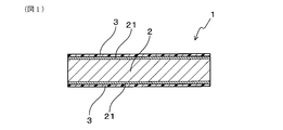
- FIG. 1 is a cross-sectional view of a precoated fin material in an example.
- FIG. 2 is an explanatory diagram of the self-potential measuring device in the embodiment.
- the precoated fin material has a base material and a resin film provided on one side or both sides of the base material. The configuration of each part of the precoated fin material will be described below.
- the aluminum constituting the substrate may be pure aluminum or an aluminum alloy.
- the substrate may be composed of pure aluminum with chemical compositions represented by alloy numbers such as A1200 and A1050.
- undercoat Film An undercoat film made of an inorganic substance is provided on the surface of the substrate, and the resin film may be laminated on the undercoat film.
- the base film may be, for example, a chemical conversion film formed by chemical conversion treatment.
- the chemical conversion film may be formed by a reactive chemical conversion treatment, or may be formed by a coating-type chemical conversion treatment.
- the underlying film includes a chromium-containing film formed by chromate treatment using chromate phosphate or the like, and chromium such as titanium phosphate, zirconium phosphate, molybdenum phosphate, zinc phosphate and zirconium oxide.
- a chromium-free film or the like formed by non-chromate treatment using a non-containing compound can be employed.
- Resin Coating At least one surface of the precoated fin material is provided with a resin coating.
- the resin coating may be directly laminated on the substrate, or may be laminated on the base film. Moreover, the resin film may be exposed on the outermost surface of the precoated fin material.
- the resin film preferably contains one or more resins selected from the group consisting of (meth)acrylic resins and urethane resins. Resin films containing these resins are excellent in corrosion resistance and hydrophilicity, and are also excellent in lubricity during press molding. Therefore, the press moldability of the precoated fin material can be further improved by providing the resin film on the outermost surface.
- the (meth)acrylic resin has the largest peak within the wave number range of 1505 to 1515 cm -1 in the Fourier transform infrared absorption spectrum obtained by the total reflection measurement method. , has the apex of the second largest peak within the wavenumber range of 1605-1615 cm ⁇ 1 and has the apex of the third largest peak within the wavenumber range of 1550-1560 cm ⁇ 1 .
- the urethane resin has the largest peak apex in the range of wave numbers 1505 to 1515 cm ⁇ 1 in the Fourier transform infrared absorption spectrum obtained by the total reflection measurement method, and the wave number 1360 to 1370 cm ⁇ It preferably has the apex of the second largest peak within the range of 1 and the apex of the third largest peak within the wavenumber range of 1555-1565 cm ⁇ 1 .
- the resin film may contain additives for paint within a range that does not impair the effects described above.
- additives include pigments, antirust agents, water-based organic resins, surfactants, rheology control agents, surface control agents, ionic liquids, antifoaming agents, and film-forming aids.
- the mass per unit area of the resin film in the precoated fin material is 0.2 g/m 2 or more and 2.5 g/m 2 or less. Since the precoated fin material has a potential difference with the base material and a contact angle of water after immersion in running water within the above-mentioned specific ranges, the thickness of the resin film is reduced to It can be very thin with a mass per unit area of 0.2 g/m 2 . As a result, it is possible to easily reduce the amount of paint used in the process of manufacturing the precoated fin material, thereby reducing manufacturing costs.
- the mass per unit area of the resin film is less than 0.2 g/m 2 , the thickness of the resin film becomes too thin, which may lead to deterioration in corrosion resistance of the precoated fin material.
- the mass per unit area of the resin film exceeds 2.5 g/m 2 , the amount of paint used in the process of manufacturing the precoated fin material increases, which may lead to an increase in manufacturing cost.
- the mass per unit area of the resin film in the precoated fin material is preferably 0.2 g/m 2 or more and 1.0 g/m 2 or less, and 0.2 g/m 2 or more and 0.9 g/m 2 or less. is more preferable. In this case, it is possible to further reduce the amount of paint used in the process of manufacturing the precoated fin material while ensuring the corrosion resistance and hydrophilicity of the precoated fin material. As a result, the effect of further reducing the manufacturing cost of the precoated fin material can be expected.
- the precoated fin material has an average self-potential value of 5% by mass NaCl aqueous solution of pH 3 for one hour after the precoated fin material is immersed in a 5% by mass NaCl aqueous solution of pH 3. It has a characteristic of being +0.040 V or more and +0.2 V or less with respect to the average value of the self-potential from the time when the base material is immersed in the water to the time when one hour has passed. Further, the precoated fin material has a property that the contact angle of water after immersing the precoated fin material in running water for 10 minutes is 20° or more and 40° or less.
- a precoated fin material in which the potential difference between the precoated fin material and the substrate and the contact angle of water are within the above-mentioned specific ranges can achieve both high corrosion resistance and high hydrophilicity. If the average self-potential value of the precoated fin material is less than +0.040 V with respect to the average self-potential value of the substrate, the corrosion resistance of the precoated fin material may be insufficient. Further, when the contact angle of water on the precoated fin material after being immersed in running water exceeds 40°, the hydrophilicity of the precoated fin material may be insufficient.
- Manufacturing method of precoated fin material In producing the precoated fin material, applying a paint containing a resin on at least one surface of the substrate; The resin film may be formed on the base material by heating the base material coated with the paint in a heating furnace at a temperature of 240° C. or more and 300° C. or less for 4 seconds or more and 20 seconds or less to bake the paint. .
- an aluminum plate can be used as the base material.
- the thickness of the substrate may be, for example, within the range of 0.05 to 0.30 mm.
- the base material may be subjected to surface treatment such as chemical conversion treatment before the coating is applied. By subjecting the surface of the substrate to a chemical conversion treatment in advance, it is possible to form a base film on the substrate and improve the adhesion of the resin film.
- Paints contain resins and additives and solvents that are blended as necessary.
- the method of applying the coating material to the substrate is not particularly limited, and various methods such as bar coater and roll coater can be employed.
- the base material After coating the base material with the paint, the base material is heated in a heating furnace at a temperature of 240°C or more and 300°C or less for 4 seconds or more and 20 seconds or less to bake the paint. Thereby, the resin film can be formed. If the temperature in the heating furnace is lower than the specific range, or if the baking time is shorter than the specific range, the paint will not be heated sufficiently, and the corrosion resistance of the precoated fin material may deteriorate. be. Further, when the temperature in the heating furnace is higher than the specific range, the paint is excessively heated, which may lead to deterioration of the resin film.
- the base material it is preferable to heat the base material so that the maximum temperature (Peak Metal Temperature, PMT) in the dry state of the base material is within the range of 170°C or higher and 220°C or lower.
- PMT Peak Metal Temperature
- the resin film can be sufficiently cured, and a precoated fin material having excellent corrosion resistance and hydrophilicity can be obtained more reliably.
- precoated fin material examples of the precoated fin material and its manufacturing method will be described with reference to FIGS.
- the specific aspects of the precoated fin material and the method of manufacturing the same according to the present invention are not limited to the aspects of the examples, and the configuration can be changed as appropriate without departing from the gist of the present invention.
- the precoated fin material 1 of this example has a base material 2 made of aluminum and resin films 3 provided on both sides of the base material 2, as shown in FIG. A base film 21 is interposed between the substrate 2 and the resin film 3 .
- the resin film 3 contains resin.
- 12 types of precoated fin materials (test materials A1 to A12) with different resin types and mass per unit area of the resin film were prepared, and various characteristics were evaluated using these. make an assessment. The specific configuration and preparation method of the test material will be described below.
- the substrate 2 of this example is an aluminum plate made of A1050 aluminum and having a thickness of 0.1 mm.
- the surface of the base material 2 is covered with an undercoat film 21 .
- the undercoat film 21 of this example is a chromate film formed by chromate treatment using chromate phosphate. The amount of the chromate film deposited was 20 mg/m 2 as the mass of Cr atoms per side of the substrate.
- the resin film 3 of this example contains either acrylic resin or urethane resin.
- a paint is prepared by adding pure water to the resin shown in Table 1 so that the solid content becomes 7% by mass.
- the paint After applying the paint using a bar coater on the base film 21 of the substrate 2 prepared in advance, the paint is pre-dried. After that, the substrate 2 is placed in a heating furnace maintained at the temperature shown in Table 1 and heated for the time shown in Table 1 to bake the paint. The atmosphere in the heating furnace is forcibly convected by a fan. Table 1 shows the maximum temperature (PMT) of the base material calculated from the temperature in the furnace and the wind speed of the fan.
- PMT maximum temperature
- the precoated fin material 1 is taken out from the heating furnace and cooled to room temperature. As described above, the test materials A1 to A12 shown in Table 1 can be obtained.
- test materials R1 and R2 shown in Table 1 are test materials for comparison with the test materials A1 to A12.
- Test material R1 and test material R2 can be prepared in the same manner as test materials A1 to A9, except that the paint baking conditions are changed as shown in Table 1.
- a measuring device 4 shown in FIG. 2 is used for measuring the natural potential of the precoated fin material and the base material.
- the measurement device 4 includes a first container 41 containing a solution for immersing the test piece 5, a second container 42 containing a solution for immersing the reference electrode 6, and the solution in the first container 41. a salt bridge 43 for electrically connecting the solution in the second container 42; a potentiostat 44 for measuring the potential of the test strip 5 with respect to the reference electrode 6; and a recording device 45 .
- a rectangular test piece 5 with a length of 40 mm and a width of 10 mm is taken from the test material or base material.
- a connecting portion 51 to the potentiostat 44 is provided at one end of the test piece 5 in the longitudinal direction, and a square potential measuring portion 52 having a side of 5 mm is provided at the other end.
- an insulating paint 53 is applied to the portions other than the connecting portion 51 and the potential measuring portion 52 .
- a 5% NaCl aqueous solution whose pH is adjusted to 3 using acetic acid is prepared in the first container 41 and a saturated NaCl aqueous solution is prepared in the second container 42 . Then, the solution in the first container 41 and the solution in the second container 42 are electrically connected via the salt bridge 43 .
- the connecting portion 51 of the test piece 5 and the reference electrode 6 are connected to the potentiostat 44, respectively.
- the reference electrode 6 for example, an Ag/AgCl electrode can be used.
- the potential measuring part 52 of the test piece 5 is immersed in the 5% NaCl aqueous solution in the first container 41, and the reference electrode 6 is immersed in the saturated NaCl aqueous solution in the second container 42, thereby
- the self-potential of the test piece 5 with reference to 6 can be measured.
- the natural potential of the test piece 5 is measured every 3 minutes and recorded in the recording device 45 .
- the self-potential of the test piece gradually decreases as time passes from the start of measurement, and shows a tendency to reach a generally constant value after 10 hours have passed.
- the average value of the self-potential from the start of measurement to the time when one hour has passed is taken as the value of the self-potential of the test material.
- Table 1 shows the self-potential value of each test material.
- the same measurement as above is performed using the base material 2 before the resin film 3 is formed. Then, the average value of the self-potential from the start of the measurement to the time when one hour has passed is taken as the value of the self-potential of the substrate.
- the natural potential of the substrate is -0.725 V vs Ag/AgCl.
- the "potential difference" column in Table 1 shows the value obtained by subtracting the natural potential of the substrate 2 from the natural potential of the test material.
- the base material 2 manufactured by polishing the surface of the precoated fin material 1 and removing the resin film 3 and the base film 21 can also be used.
- test piece is taken from each test material and then immersed in running water at a temperature of 25°C and a flow rate of 5 L/min for 10 minutes. 2 ⁇ L of pure water is dropped on the surface of the test material taken out from the running water, and the contact angle of water is measured 30 seconds after dropping. Table 1 shows the water contact angle of each test material.
- Corrosion resistance A rectangular test piece of 100 mm long and 50 mm wide is taken from the test material so that the rolling direction and the longitudinal direction of the base material 2 are parallel. Using this test piece, a salt spray test is carried out by a method conforming to JIS Z2371:2000. The test time shall be 1000 hours. The corrosion area ratio of the test material after the test is calculated, and the rating number is determined by the rating number method of JIS Z2371:2000. A higher rating number indicates better corrosion resistance. Table 1 shows the rating number of each test material.
- the mass per unit area of the resin film of the test materials A1 to A12, the potential difference with the substrate, and the water contact angle after immersion in flowing water are within the above-mentioned specific ranges. Therefore, these test materials have excellent corrosion resistance and hydrophilicity.
- the resin film of the test material R1 is formed by heating at a furnace temperature lower than that of the test materials A1 to A12. Therefore, the potential difference between the test material R1 and the substrate is smaller than the specific range. As a result, the corrosion resistance of test material R1 is inferior to test materials A1 to A12.
- the resin film of test material R2 is formed by heating at a higher furnace temperature than test materials A1 to A12. Therefore, the resin film deteriorates and discolors during heating.
Landscapes
- Engineering & Computer Science (AREA)
- Chemical & Material Sciences (AREA)
- Wood Science & Technology (AREA)
- Life Sciences & Earth Sciences (AREA)
- Materials Engineering (AREA)
- Organic Chemistry (AREA)
- Mechanical Engineering (AREA)
- Thermal Sciences (AREA)
- General Engineering & Computer Science (AREA)
- Physics & Mathematics (AREA)
- Metallurgy (AREA)
- Chemical Kinetics & Catalysis (AREA)
- Application Of Or Painting With Fluid Materials (AREA)
- Paints Or Removers (AREA)
- Laminated Bodies (AREA)
- Other Surface Treatments For Metallic Materials (AREA)
Abstract
Description
前記樹脂皮膜の単位面積当たりの質量が0.2g/m2以上2.5g/m2以下であり、
pH3の5質量%NaCl水溶液に前記プレコートフィン材を浸漬した時点から1時間が経過した時点までの自然電位の平均値が、pH3の5質量%NaCl水溶液に前記基材を浸漬した時点から1時間が経過した時点までの自然電位の平均値に対して+0.040V以上+0.2V以下となり、かつ、
前記プレコートフィン材を流水に10分間浸漬した後の水の接触角が20°以上40°以下となる特性を有する、プレコートフィン材にある。
前記基材の少なくとも一方の面上に、樹脂を含む塗料を塗布し、
前記塗料が塗布された前記基材を温度240℃以上300℃以下の加熱炉内で4秒以上20秒以下加熱して塗装焼付を行うことにより前記基材上に前記樹脂皮膜を形成する、プレコートフィン材の製造方法にある。
前記プレコートフィン材は、基材と、基材の片面または両面上に設けられた樹脂皮膜とを有している。以下、プレコートフィン材の各部の構成について説明する。
前記プレコートフィン材において、基材を構成するアルミニウムは、純アルミニウムであってもよいし、アルミニウム合金であってもよい。例えば、基材は、A1200やA1050等の合金番号で表される化学成分を備えた純アルミニウムから構成されていてもよい。
基材の表面には、無機物からなる下地皮膜が設けられており、樹脂皮膜は下地皮膜上に積層されていてもよい。基材と樹脂皮膜との間に下地皮膜を設けることにより、樹脂皮膜の密着性をより向上させたり、基材の耐食性をより向上させたりすることができる。
プレコートフィン材の少なくとも一方の面には、樹脂皮膜が設けられている。樹脂皮膜は、基材に直接積層されていてもよいし、下地皮膜上に積層されていてもよい。また、樹脂皮膜は、プレコートフィン材の最表面に露出していてもよい。
前記プレコートフィン材は、pH3の5質量%NaCl水溶液に前記プレコートフィン材を浸漬した時点から1時間が経過した時点までの自然電位の平均値が、pH3の5質量%NaCl水溶液に前記基材を浸漬した時点から1時間が経過した時点までの自然電位の平均値に対して+0.040V以上+0.2V以下となる特性を有している。また、前記プレコートフィン材は、プレコートフィン材を流水に10分間浸漬した後の水の接触角が20°以上40°以下となる特性を有している。
前記プレコートフィン材を作製するに当たっては、
前記基材の少なくとも一方の面上に、樹脂を含む塗料を塗布し、
前記塗料が塗布された前記基材を温度240℃以上300℃以下の加熱炉内で4秒以上20秒以下加熱して塗装焼付を行うことにより前記基材上に前記樹脂皮膜を形成すればよい。
本例の基材2は、A1050アルミニウムからなる厚み0.1mmのアルミニウム板である。基材2の表面は、下地皮膜21により覆われている。本例の下地皮膜21は、具体的には、リン酸クロメートを用いたクロメート処理により形成されるクロメート皮膜である。クロメート皮膜の付着量は、基材の片面当たり、Cr原子の質量として20mg/m2である。
本例の樹脂皮膜3には、アクリル樹脂またはウレタン樹脂のいずれかが含まれている。
まず、表1に記載した樹脂に、固形分量が7質量%となるように純水を加えて塗料を調製する。
・プレコートフィン材と基材との電位差の測定
プレコートフィン材及び基材の自然電位の測定には、図2に示す測定装置4が用いられる。測定装置4は、試験片5を浸漬するための溶液を入れる第1の容器41と、参照電極6を浸漬するための溶液を入れる第2の容器42と、第1の容器41内の溶液と第2の容器42内の溶液とを電気的に接続するための塩橋43と、参照電極6に対する試験片5の電位を測定するためのポテンシオスタット44と、測定した電位を記録するための記録装置45と、を有している。
各試験材から試験片を採取したのち、温度25℃、流速5L/分の流水中に10分間浸漬する。流水から取り出した試験材の表面に2μLの純水を滴下し、滴下した時点から30秒後に水の接触角を測定する。表1に、各試験材の水の接触角を示す。
各試験材から一辺100mmの正方形状の試験片を採取する。この試験片の質量W1(単位:g)を測定した後、500℃の電気炉内で試験片を15分間加熱する。電気炉から取り出した試験片の質量W2(単位:g)を測定した後、加熱前からの質量の減少量W1-W2(単位:g)を算出する。この質量の減少量W1-W2を、試験片上に形成された樹脂皮膜3の総面積S(単位:cm2)で除することにより、樹脂皮膜3の単位面積当たりの質量を算出することができる。表1に、各試験材における樹脂皮膜3の単位面積当たりの質量を示す。
試験材から、基材2の圧延方向と長手方向とが並行になるようにして縦100mm、横50mmの長方形状の試験片を採取する。この試験片を用い、JIS Z2371:2000に準拠した方法により塩水噴霧試験を実施する。試験時間は1000時間とする。試験後の試験材の腐食面積率を算出し、JIS Z2371:2000のレイティングナンバ法によりレイティングナンバを決定する。レイティングナンバは、値が大きいほど優れた耐食性を有することを示す。表1に、各試験材のレイティングナンバを示す。
試験材の表面を目視により観察し、樹脂皮膜3の性状を評価する。

Claims (3)
- アルミニウムからなる基材と、前記基材の少なくとも一方の面上に設けられ、最表面に露出した樹脂皮膜と、を有するプレコートフィン材であって、
前記樹脂皮膜の単位面積当たりの質量が0.2g/m2以上2.5g/m2以下であり、
pH3の5質量%NaCl水溶液に前記プレコートフィン材を浸漬した時点から1時間が経過した時点までの自然電位の平均値が、pH3の5質量%NaCl水溶液に前記基材を浸漬した時点から1時間が経過した時点までの自然電位の平均値に対して+0.040V以上+0.2V以下となり、かつ、
前記プレコートフィン材を流水に10分間浸漬した後の水の接触角が20°以上40°以下となる特性を有する、プレコートフィン材。 - 前記樹脂皮膜には、(メタ)アクリル樹脂及びウレタン樹脂からなる群より選択される1種または2種以上の樹脂が含まれている、請求項1に記載のプレコートフィン材。
- 請求項1または2に記載のプレコートフィン材の製造方法であって、
前記基材の少なくとも一方の面上に、樹脂を含む塗料を塗布し、
前記塗料が塗布された前記基材を温度240℃以上300℃以下の加熱炉内で4秒以上20秒以下加熱して塗装焼付を行うことにより前記基材上に前記樹脂皮膜を形成する、プレコートフィン材の製造方法。
Priority Applications (1)
| Application Number | Priority Date | Filing Date | Title |
|---|---|---|---|
| CN202280039954.6A CN117460923A (zh) | 2021-07-08 | 2022-06-27 | 预涂翅片材料及其制造方法 |
Applications Claiming Priority (2)
| Application Number | Priority Date | Filing Date | Title |
|---|---|---|---|
| JP2021113420A JP2023009820A (ja) | 2021-07-08 | 2021-07-08 | プレコートフィン材及びその製造方法 |
| JP2021-113420 | 2021-07-08 |
Publications (1)
| Publication Number | Publication Date |
|---|---|
| WO2023282111A1 true WO2023282111A1 (ja) | 2023-01-12 |
Family
ID=84801512
Family Applications (1)
| Application Number | Title | Priority Date | Filing Date |
|---|---|---|---|
| PCT/JP2022/025574 Ceased WO2023282111A1 (ja) | 2021-07-08 | 2022-06-27 | プレコートフィン材及びその製造方法 |
Country Status (3)
| Country | Link |
|---|---|
| JP (1) | JP2023009820A (ja) |
| CN (1) | CN117460923A (ja) |
| WO (1) | WO2023282111A1 (ja) |
Citations (5)
| Publication number | Priority date | Publication date | Assignee | Title |
|---|---|---|---|---|
| JP2009150586A (ja) * | 2007-12-19 | 2009-07-09 | Sumitomo Light Metal Ind Ltd | 熱交換器用フィン材 |
| WO2017038251A1 (ja) * | 2015-08-28 | 2017-03-09 | 日本パーカライジング株式会社 | 表面処理剤、皮膜の製造方法及び皮膜付き金属材料 |
| WO2017141943A1 (ja) * | 2016-02-15 | 2017-08-24 | 株式会社Uacj | 熱交換器 |
| JP2019218617A (ja) * | 2018-06-21 | 2019-12-26 | 日本軽金属株式会社 | 耐座屈性に優れた熱交換器用アルミニウム合金フィン材及びその製造方法 |
| WO2020022213A1 (ja) * | 2018-07-24 | 2020-01-30 | 株式会社Uacj | プレコートアルミニウム材 |
Family Cites Families (3)
| Publication number | Priority date | Publication date | Assignee | Title |
|---|---|---|---|---|
| JP2007070435A (ja) * | 2005-09-06 | 2007-03-22 | Furukawa Sky Kk | 親水性被覆下地用樹脂組成物、アルミニウム合金塗装板及びその製造方法 |
| JP2019086267A (ja) * | 2017-11-10 | 2019-06-06 | 株式会社Uacj | プレコートフィン材 |
| JP7058176B2 (ja) * | 2018-05-21 | 2022-04-21 | 株式会社Uacj | アルミニウム合金製熱交換器 |
-
2021
- 2021-07-08 JP JP2021113420A patent/JP2023009820A/ja active Pending
-
2022
- 2022-06-27 CN CN202280039954.6A patent/CN117460923A/zh active Pending
- 2022-06-27 WO PCT/JP2022/025574 patent/WO2023282111A1/ja not_active Ceased
Patent Citations (5)
| Publication number | Priority date | Publication date | Assignee | Title |
|---|---|---|---|---|
| JP2009150586A (ja) * | 2007-12-19 | 2009-07-09 | Sumitomo Light Metal Ind Ltd | 熱交換器用フィン材 |
| WO2017038251A1 (ja) * | 2015-08-28 | 2017-03-09 | 日本パーカライジング株式会社 | 表面処理剤、皮膜の製造方法及び皮膜付き金属材料 |
| WO2017141943A1 (ja) * | 2016-02-15 | 2017-08-24 | 株式会社Uacj | 熱交換器 |
| JP2019218617A (ja) * | 2018-06-21 | 2019-12-26 | 日本軽金属株式会社 | 耐座屈性に優れた熱交換器用アルミニウム合金フィン材及びその製造方法 |
| WO2020022213A1 (ja) * | 2018-07-24 | 2020-01-30 | 株式会社Uacj | プレコートアルミニウム材 |
Also Published As
| Publication number | Publication date |
|---|---|
| JP2023009820A (ja) | 2023-01-20 |
| CN117460923A (zh) | 2024-01-26 |
Similar Documents
| Publication | Publication Date | Title |
|---|---|---|
| CN109804102B (zh) | 表面处理溶液组合物、利用该组合物进行表面处理的镀锌系钢板及其制造方法 | |
| JP6653026B2 (ja) | 鋼板表面処理用溶液組成物、それを用いて表面処理された亜鉛系めっき鋼板、及びその製造方法 | |
| JP2009057587A5 (ja) | ||
| JPS60205194A (ja) | 熱交換器のフイン材 | |
| JP6061755B2 (ja) | アルミニウムフィン材およびその製造方法 | |
| WO2010110261A1 (ja) | 熱交換器用アルミニウムフィン材 | |
| JP2003201577A (ja) | 熱交換器フィン用アルミニウム又はアルミニウム合金材及び熱交換器用フィン | |
| WO2023282111A1 (ja) | プレコートフィン材及びその製造方法 | |
| JP7445185B2 (ja) | 表面処理鋼材 | |
| AU2021379233B2 (en) | Surface-treated metal sheet | |
| JP7502232B2 (ja) | アルミニウム製フィン材 | |
| JP7609712B2 (ja) | アルミニウム製フィン材及び着氷霜抑制剤 | |
| JP2002266081A (ja) | 塗装前処理用化成処理液及び塗装用化成処理鋼板 | |
| JP7651361B2 (ja) | アルミニウム製フィン材 | |
| JPH05125555A (ja) | プレス成形性に優れたプレコートフイン材 | |
| JP7193443B2 (ja) | アルミニウム製フィン材 | |
| JP7485533B2 (ja) | アルミニウム製フィン材 | |
| JPS59153884A (ja) | 塗装下地用亜鉛または亜鉛合金めつき鋼板 | |
| JP3274077B2 (ja) | 撥水性及び着霜防止性が優れたアルミニウム又はアルミニウム合金部材 | |
| JP2002235179A (ja) | 塗装鋼板用塗装前処理液及び処理鋼板 | |
| JPH02103133A (ja) | 熱交換器用アルミニウムフイン材 | |
| JP7491715B2 (ja) | アルミニウム製フィン材 | |
| JP7817560B2 (ja) | 表面処理鋼材 | |
| CN115003980B (zh) | 铝翅片材、热交换器和铝翅片材的制造方法 | |
| JP3600759B2 (ja) | 加工性に優れたリン酸塩処理亜鉛系メッキ鋼板およびその製造方法 |
Legal Events
| Date | Code | Title | Description |
|---|---|---|---|
| 121 | Ep: the epo has been informed by wipo that ep was designated in this application |
Ref document number: 22837527 Country of ref document: EP Kind code of ref document: A1 |
|
| WWE | Wipo information: entry into national phase |
Ref document number: 202280039954.6 Country of ref document: CN |
|
| WWE | Wipo information: entry into national phase |
Ref document number: 2301008381 Country of ref document: TH |
|
| NENP | Non-entry into the national phase |
Ref country code: DE |
|
| 122 | Ep: pct application non-entry in european phase |
Ref document number: 22837527 Country of ref document: EP Kind code of ref document: A1 |