WO2023281610A1 - ガラス板、円板状ガラス、および磁気ディスク用ガラス基板 - Google Patents
ガラス板、円板状ガラス、および磁気ディスク用ガラス基板 Download PDFInfo
- Publication number
- WO2023281610A1 WO2023281610A1 PCT/JP2021/025369 JP2021025369W WO2023281610A1 WO 2023281610 A1 WO2023281610 A1 WO 2023281610A1 JP 2021025369 W JP2021025369 W JP 2021025369W WO 2023281610 A1 WO2023281610 A1 WO 2023281610A1
- Authority
- WO
- WIPO (PCT)
- Prior art keywords
- glass plate
- glass
- less
- flatness
- heat treatment
- Prior art date
- Legal status (The legal status is an assumption and is not a legal conclusion. Google has not performed a legal analysis and makes no representation as to the accuracy of the status listed.)
- Ceased
Links
Images


Classifications
-
- G—PHYSICS
- G11—INFORMATION STORAGE
- G11B—INFORMATION STORAGE BASED ON RELATIVE MOVEMENT BETWEEN RECORD CARRIER AND TRANSDUCER
- G11B5/00—Recording by magnetisation or demagnetisation of a record carrier; Reproducing by magnetic means; Record carriers therefor
- G11B5/62—Record carriers characterised by the selection of the material
- G11B5/73—Base layers, i.e. all non-magnetic layers lying under a lowermost magnetic recording layer, e.g. including any non-magnetic layer in between a first magnetic recording layer and either an underlying substrate or a soft magnetic underlayer
- G11B5/739—Magnetic recording media substrates
- G11B5/73911—Inorganic substrates
- G11B5/73921—Glass or ceramic substrates
-
- C—CHEMISTRY; METALLURGY
- C03—GLASS; MINERAL OR SLAG WOOL
- C03B—MANUFACTURE, SHAPING, OR SUPPLEMENTARY PROCESSES
- C03B17/00—Forming molten glass by flowing-out, pushing-out, extruding or drawing downwardly or laterally from forming slits or by overflowing over lips
- C03B17/06—Forming glass sheets
-
- C—CHEMISTRY; METALLURGY
- C03—GLASS; MINERAL OR SLAG WOOL
- C03B—MANUFACTURE, SHAPING, OR SUPPLEMENTARY PROCESSES
- C03B17/00—Forming molten glass by flowing-out, pushing-out, extruding or drawing downwardly or laterally from forming slits or by overflowing over lips
- C03B17/06—Forming glass sheets
- C03B17/064—Forming glass sheets by the overflow downdraw fusion process; Isopipes therefor
-
- C—CHEMISTRY; METALLURGY
- C03—GLASS; MINERAL OR SLAG WOOL
- C03B—MANUFACTURE, SHAPING, OR SUPPLEMENTARY PROCESSES
- C03B25/00—Annealing glass products
- C03B25/02—Annealing glass products in a discontinuous way
-
- C—CHEMISTRY; METALLURGY
- C03—GLASS; MINERAL OR SLAG WOOL
- C03B—MANUFACTURE, SHAPING, OR SUPPLEMENTARY PROCESSES
- C03B25/00—Annealing glass products
- C03B25/02—Annealing glass products in a discontinuous way
- C03B25/025—Glass sheets
-
- G—PHYSICS
- G11—INFORMATION STORAGE
- G11B—INFORMATION STORAGE BASED ON RELATIVE MOVEMENT BETWEEN RECORD CARRIER AND TRANSDUCER
- G11B5/00—Recording by magnetisation or demagnetisation of a record carrier; Reproducing by magnetic means; Record carriers therefor
- G11B5/62—Record carriers characterised by the selection of the material
- G11B5/73—Base layers, i.e. all non-magnetic layers lying under a lowermost magnetic recording layer, e.g. including any non-magnetic layer in between a first magnetic recording layer and either an underlying substrate or a soft magnetic underlayer
-
- G—PHYSICS
- G11—INFORMATION STORAGE
- G11B—INFORMATION STORAGE BASED ON RELATIVE MOVEMENT BETWEEN RECORD CARRIER AND TRANSDUCER
- G11B5/00—Recording by magnetisation or demagnetisation of a record carrier; Reproducing by magnetic means; Record carriers therefor
- G11B5/84—Processes or apparatus specially adapted for manufacturing record carriers
-
- G—PHYSICS
- G11—INFORMATION STORAGE
- G11B—INFORMATION STORAGE BASED ON RELATIVE MOVEMENT BETWEEN RECORD CARRIER AND TRANSDUCER
- G11B5/00—Recording by magnetisation or demagnetisation of a record carrier; Reproducing by magnetic means; Record carriers therefor
- G11B5/84—Processes or apparatus specially adapted for manufacturing record carriers
- G11B5/8404—Processes or apparatus specially adapted for manufacturing record carriers manufacturing base layers
Definitions
- the FPD uses a glass substrate on which electronic elements such as thin film transistors (TFTs) are provided.
- TFTs thin film transistors
- the glass substrate is heated to a high temperature, so there is a problem that the glass substrate is thermally shrunk and the dimensions are easily changed. Therefore, when a glass plate is produced by the above-described method such as the float method, the glass plate is slowly cooled while being shaped, and the conditions for slow cooling are adjusted to reduce the residual stress of the glass plate. It has been attempted to reduce the thermal shrinkage rate.
- off-line annealing is known, in which a glass plate cut into a predetermined size from a molded long glass sheet is heat-treated ( Patent document 1).
- a glass substrate for a magnetic disk is produced from a glass plate having a high glass transition temperature (Tg) produced by the above-described method such as the float method. It has been found that the flatness of the magnetic disk deteriorates due to thermal contraction and deformation of the magnetic disk. It has become clear that such a deterioration in flatness occurs particularly when a magnetic disk glass substrate having a small thickness is used. If the flatness of the magnetic disk is poor, fluttering is likely to occur in the HDD device, and stable reading cannot be performed.
- Tg glass transition temperature
- the glass plate is annealed to reduce the thermal shrinkage
- the glass plate before the annealing treatment has an anisotropic thermal shrinkage rate in which the magnitude of the thermal shrinkage rate varies depending on the in-plane direction of the region of the glass plate corresponding to the region to be measured, Among the in-plane directions, the difference between the thermal contraction amount S1 of the region in the direction in which the thermal contraction rate is the minimum and the thermal contraction amount S2 of the region in the direction in which the thermal contraction rate is the maximum is greater than 1.0 ⁇ m.
- the glass plate is a rectangular glass plate having a plate thickness of less than 0.68 mm, a flatness of 30 ⁇ m or less, and two orthogonal sides each having a length of 95 to 120 mm, After being maintained at 700° C. for 4 hours, the heat shrinkage rate is 130 ppm or less when subjected to the first heat treatment of cooling from 700° C. to 400° C. at a rate of 50° C./hour,
- Tg glass transition temperature
- the amount of change in flatness due to the second heat treatment in which Tg is maintained at ⁇ 160° C. for 60 seconds and then cooled to room temperature in the atmosphere is 10 ⁇ m or less. It is characterized by
- the rectangular glass plate is a base plate from which a disk-shaped glass having a circular outer periphery is formed, It is preferable that the area of the main surface of the rectangular glass plate is 1.6 times or less as large as the inner area of the outer circumference of the disk-shaped glass.
- the magnetic disk glass substrate has a thickness of less than 0.68 mm, a flatness of 30 ⁇ m or less, and a diameter of 95 to 100 mm, After being maintained at 700° C. for 4 hours, the heat shrinkage rate is 130 ppm or less when subjected to the first heat treatment of cooling from 700° C. to 400° C. at a rate of 50° C./hour,
- Tg glass transition temperature
- the amount of change in flatness due to the second heat treatment in which the temperature is maintained at Tg ⁇ 160° C. for 60 seconds and then cooled to room temperature in the air is It is characterized by being 10 ⁇ m or less.
- (a) is an external view of a glass plate (large plate glass) according to an embodiment, and (b) is a plan view for explaining a region to be measured of the glass plate.
- (a) is an external view of a glass plate (singulated glass) according to an embodiment, and (b) is a plan view of the glass plate showing a portion to be disc-shaped glass.
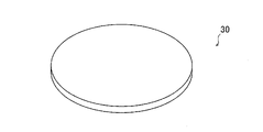
- 1 is an external view of a disk-shaped glass that is an embodiment;
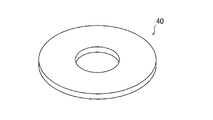
- FIG. BRIEF DESCRIPTION OF THE DRAWINGS It is an external view of the glass substrate for magnetic discs which is one Embodiment.
- FIG. 1(a) shows an external view of a glass plate 10 according to one embodiment. Further, FIG. 1(b) shows a plan view for explaining a region 13 to be measured of the glass plate 10, which will be described later.
- the central region 12 of the glass plate 10 is defined as the end of the length Le of 5 to 20% of the length L of the short side 10a of the glass plate 10 inside the glass plate 10 from both ends of the short side direction of the glass plate 10.
- An end region 11b with a length We of 5 to 20% of the length W of the long side 10b of the glass plate 10 is formed inside the glass plate 10 from each of the end regions 11a or both ends in the long side direction of the glass plate 10. It means the area of the glass plate 10 that has been removed.
- the length of the central region 12 in the short side direction is Lc
- the length in the long side direction is Wc.
- the glass plate 10 of the present embodiment is subjected to the first heat treatment in which the region to be measured 13 is maintained at 700° C. for 4 hours, and then cooled from 700° C. to 400° C. at a rate of 50° C./hour.
- the thermal contraction rate of the measured region 13 is set to 130 ppm or less, and the measured region 13 is maintained at Tg-160 ° C. for 60 seconds, and then cooled to room temperature in the atmosphere.
- the amount of change in flatness is set to 10 ⁇ m or less.
- the length (diameter) in 25 directions that are changed by 7.2 degrees in the circumferential direction with respect to the center of the measurement object can be used. can. By measuring the amount of thermal contraction in 25 directions and subtracting the minimum value from the maximum value among them, the difference (absolute value) in the amount of thermal contraction can be obtained.
- the thermal shrinkage rate of the measured region 13 is preferably 90 ppm or less, more preferably 50 ppm or less.
- the amount of change in flatness of the measurement target region 13 is preferably 7.5 ⁇ m or less, more preferably 5 ⁇ m or less.
- the glass plate 10 is a portion cut out from a long glass sheet formed using any one of the float method, the Fourcor method, the Pittsburgh method, the downdraw method, the Colburn method, and the redraw method. preferable.
- a glass sheet 10 having a large size can be obtained from the glass sheet formed by these methods. Therefore, from the glass plate 10, it is possible to obtain a large amount of singulated glass that is the basis of the glass substrate for a magnetic disk. It is possible to reduce the manufacturing cost of the glass substrate for Moreover, since these methods are advantageous for forming a glass sheet with a high glass transition temperature (Tg), the manufacturing cost of the glass plate 10 with a high glass transition temperature (Tg) can be reduced.
- Specific examples of the down-draw method include the slot down-draw method and the overflow down-draw method.
- the glass plate 10 may have an anisotropic thermal contraction rate.
- the anisotropy of thermal shrinkage refers to a characteristic in which the magnitude of the thermal shrinkage varies depending on the in-plane direction of the region 13 to be measured. According to the studies of the present inventors, if the glass plate 10 has an anisotropic thermal shrinkage rate, when the magnetic film in the magnetic disk glass substrate obtained from the glass plate 10 is subjected to heat treatment, the glass It became clear that the circularity of the substrate (JIS B0621-1984) might deteriorate.
- the glass plate material that is the source of the glass plate 10 is a portion cut out from a glass sheet formed using the above-described method such as the float method, the difference in thermal contraction rate depending on the in-plane direction of the glass sheet is likely to occur, and anisotropy in thermal shrinkage is likely to occur. If the roundness of the outer circumference of the glass substrate is deteriorated, blurring occurs when the magnetic disk is rotated at high speed, and fluttering is likely to occur.
- the thermal contraction amount S1 of the measurement area in the direction in which the thermal contraction rate is the minimum among the in-plane directions of the measurement area 13 and the thermal contraction rate are The difference (absolute value) from the thermal contraction amount S2 of the region to be measured in the maximum direction is preferably 1.0 ⁇ m or less.
- the glass plate 10 is preferably subjected to an annealing treatment (for example, "precision annealing” to be described later) for reducing the thermal shrinkage rate.
- the glass plate (the glass plate material that is the base of the glass plate 10) before the annealing treatment has a different thermal contraction rate depending on the in-plane direction of the region of the glass plate corresponding to the region 13 to be measured.
- the difference between the thermal contraction amount S1 of the region in the in-plane direction in which the thermal contraction rate is the minimum and the thermal contraction amount S2 in the direction in which the thermal contraction rate is the maximum ( absolute value) may be greater than 1.0 ⁇ m.
- the annealed glass plate 10 satisfies the above-described range of variation in thermal shrinkage rate and flatness.
- heat treatment is performed on the magnetic film of the magnetic disk glass substrate obtained from the glass plate 10, deterioration in flatness is suppressed.
- a square measurement area of 100 mm on a side cut out from the entire glass plate 10 including the end regions 11a and 11b of the glass plate 10 has flatness, flatness, It is preferable that the thermal shrinkage rate and the amount of change in flatness each satisfy the above ranges.
- a larger number of magnetic-disk glass substrates can be produced from such a glass plate 10 than in the case of producing magnetic-disk glass substrates from the central region 12 .
- the material of the glass plate 10 for example, it is preferable to use aluminosilicate glass, soda lime glass, soda aluminosilicate glass, aluminoborosilicate glass, borosilicate glass, or the like.
- a small piece of glass is extracted from a conventional glass plate manufactured by the above-described method such as the float method to prepare a glass substrate for a magnetic disk, and a magnetic material serving as a magnetic recording layer is obtained. It has been found that when the film is heat-treated, the glass substrate is thermally shrunk and flexed, degrading the flatness of the magnetic disk. Since the glass sheet formed by the above-described methods such as the float method is rapidly cooled while maintaining a large area, it is difficult to keep the temperature constant over the entire surface of the glass sheet, and the thermal shrinkage rate is evenly reduced over the entire surface of the glass sheet. difficult.
- the thermal contraction rate varies within the surface of the glass sheet. For this reason, when a portion of the glass sheet is extracted from the glass sheet and heated later, the amount of heat shrinkage may be large. That is, when used as a glass substrate for FPD, it is used with a large area. Although it was not necessary to consider it, since the size of the magnetic disk glass substrate is smaller than that of the FPD glass substrate, the magnetic disk glass substrate having a large thermal shrinkage rate is produced due to the in-plane variation in the thermal shrinkage rate. It turned out that there is a case. In addition, the heat treatment temperature of the magnetic film formed on the magnetic disk glass substrate has been increasing in recent years, reaching a level close to the glass transition temperature (Tg) of the glass substrate.
- Tg glass transition temperature
- the annealing effect (such as the effect of reducing the thermal shrinkage rate) does not spread uniformly over the entire surface of the glass plate material, resulting in ,
- a plurality of rectangular glasses each having a side of 95 to 120 mm, for example, can be obtained from the large plate glass.
- the heat shrinkage rate in the individualized glass plate does not fall below a predetermined value, or when the magnetic film is heat-treated as a magnetic disk glass substrate It was found that some of the pieces of glass were subject to warping, and that there were variations in properties between individual pieces of glass. In particular, when the glass plate material from which the glass plate 10 is made is a portion cut out from a glass sheet formed using the above-described method such as the float method, the edge regions near each side of the glass sheet are excluded. It has been found that the magnetic disk glass substrate produced by cutting out from the central region may have the above-described variations.
- the setter has a plate-like shape with a pair of main surfaces, and is configured such that at least one surface is in contact with the glass plate material from which the glass plate 10 is made.
- the main surface of the setter is wider than the main surface of the glass plate material from which the glass plate 10 is made, and is sized to protrude from the entire circumference of the glass plate material.
- the protruding length is, for example, 5 cm or more in the direction away from the center of the glass plate.
- the flatness of the setter is preferably less than 30 ⁇ m, more preferably 20 ⁇ m or less, even more preferably 10 ⁇ m or less, in order to efficiently obtain the glass plate 10 with a flatness of 30 ⁇ m or less.
- the thermal conductivity of the setter is, for example, 1 to 200 W/(m ⁇ K) at 20°C.
- the thermal conductivity of the setter is within the above range, when the precision annealing of the glass plate material that is the source of the glass plate 10 is performed, the glass plate material is easily heated and cooled evenly, and the thermal contraction rate after precision annealing It is possible to effectively suppress the variation in the size of .
- Materials for the setter include, for example, alumina (Al 2 O 3 ), silicon carbide (SiC), silicon nitride (Si 3 N 4 ), zirconia (ZrO 2 ), sialon (Si 3 N 4 ⁇ Al 2 O 3 ), steatite, spinel, cordierite and the like.
- alumina (Al 2 O 3 ) and silicon carbide (SiC) are preferably used.
- An example of precision annealing using a setter is a method using two setters and rock wool.
- the setter and the glass plate material are laminated so that one glass plate material is sandwiched between two setters having a larger area than the glass plate material, and two setters adjacent to the side surface (end surface) of the glass plate material are used. This is done with the gaps between them filled with highly heat-resistant rock wool.
- the two setters sandwich the glass plate material and overlap each other almost exactly vertically, and the outer peripheral part of the setter protrudes almost evenly from the glass plate material over the entire circumference, so that the gap between the two setters to be able to
- the entire glass plate is covered with the setter and rock wool, and the setter load is applied moderately and evenly to the main surface of the glass plate.
- the weight applied to the glass plate is lighter than in the case of precision annealing of a laminate formed by alternately stacking a plurality of setters and a plurality of glass plates.
- rock wool has heat insulating properties and air permeability, it can preferably block the gap between the setters. As a result, it becomes easier to uniformly heat or cool (heat uniformize) the entire glass plate, and the thermal shrinkage rate can be reduced regardless of the in-plane position of the glass plate. Further, rock wool is used to such an extent that it does not interfere with the load applied to the glass plate by the setter placed on the glass plate.
- the load of the setter is moderately and evenly applied to the main surface of the glass plate, it is possible to suppress deterioration of the flatness of the glass plate during the precision annealing treatment, and in some cases reduce the flatness. be able to.
- the influence of the weight of the setter on the glass plate is suppressed, and the heat shrinkage rate of the glass plate 10 is reduced regardless of the in-plane position, and the flatness of the glass plate is reduced. can be enhanced.
- the glass plate 10 can be manufactured by the glass plate manufacturing method including the above precision annealing.
- FIG. 2(a) shows an external view of the glass plate 20 of one embodiment.
- FIG.2(b) shows the top view of the glass plate 20 which showed the part used as disc-shaped glass with the broken line.
- the glass plate 20 is a rectangular plate having a plate thickness of less than 0.68 mm, a flatness of 30 ⁇ m or less, and two orthogonal sides each having a length of 95 to 120 mm.
- This glass plate is smaller in size than the glass plate (large glass plate) 10 described above, and is sometimes referred to as "individualized glass" in this specification.
- the glass plate 20 is a rectangular plate having a size of 95 to 120 mm. It has a size suitable for making Glass plate 20 is preferably a square plate.
- the plate thickness of the glass plate 20 is preferably less than 0.61 mm, more preferably less than 0.58 mm.
- the thermal shrinkage rate of the glass plate 20 when subjected to the first heat treatment of cooling from 700° C. to 400° C. at a rate of 50° C./hour is 130 ppm or less.
- Tg glass transition temperature
- the amount of change in the flatness of the glass plate 20 due to the second heat treatment in which Tg is maintained at ⁇ 160° C. for 60 seconds and then cooled to room temperature in the atmosphere is 10 ⁇ m or less. be.
- the glass plate 20 is a base plate that is the base of disc-shaped glass.
- the area of the main surface of the glass plate 20 is preferably 1.6 times or less, more preferably 1.5 times or less, as large as the inner area of the outer circumference of the disk-shaped glass. In this way, the area of the main surface of the glass plate 20 is close to the area of the inner periphery of the disk-shaped glass, so that the glass plate 20 has the above-described thermal contraction rate and flatness change.
- Disc-shaped glass also tends to have the two characteristics of quantity. This effect is particularly effective in the glass plate 20 produced by performing precision annealing (precision annealing after singulation) on a glass plate material that is singulated from which the glass plate 20 is made.
- the singulation means obtaining the singulated glass 20 from the large plate glass 10, or obtaining a glass plate material having the same dimensions as the singulated glass 20 from the glass plate material that is the source of the large plate glass 10. means.
- the glass plate 20 is obtained, for example, by cutting out the glass plate 10 or a piece obtained by subjecting the glass plate material, which is the base of the glass plate 10, to individual pieces and subjecting them to precision annealing.
- the glass plate 20 is preferably subjected to an annealing treatment (for example, the precision annealing described above) to reduce the thermal shrinkage.
- the glass plate (the glass plate material that is the base of the glass plate 20) before the annealing treatment has an anisotropic thermal contraction rate in which the magnitude of the thermal contraction rate varies depending on the in-plane direction of the glass plate.
- the difference (absolute value) between the thermal contraction amount S1 of the glass plate in the direction in which the thermal contraction rate is the minimum and the thermal contraction amount S2 of the glass plate in the direction in which the thermal contraction rate is the maximum is 1.0 ⁇ m can be larger.
- the difference (absolute value) between the thermal contraction amount S1 in the direction in which the thermal contraction rate is the minimum and the thermal contraction amount S2 in the direction in which the thermal contraction rate is the maximum among the in-plane directions of the glass plate 20. is preferably 1.0 ⁇ m or less.
- the glass plate 20 can be produced, for example, by performing precision annealing after singulating a glass plate material before precision annealing, which is the base of the large glass plate 10 . That is, the glass plate 20 can be manufactured by a glass plate manufacturing method that includes precision annealing of the individualized glass plate material that is the source of the glass plate 20 . The precision annealing in this method is performed in the same manner as the precision annealing described above for the large glass plate 10 , with the individualized glass plate material that is the source of the glass plate 20 being the object of heating.
- the individualized glass plate material used in this method which is the base of the glass plate 20, is, for example, a plate material obtained by cutting out the glass plate material, which is the base of the large glass plate 10, without performing precision annealing and dividing the glass plate into individual pieces. , has substantially the same dimensions and shape as the glass plate 20 .
- the glass plate 20 cut out from the precision-annealed large plate glass 10 can be obtained.
- the above-described glass plate 20 with even smaller variations in thermal shrinkage and flatness can be obtained. Therefore, by performing precision annealing on the individualized glass plate material that is the source of the glass plate 20, the glass plate 20 with even smaller variations in thermal shrinkage and flatness as described above can be obtained.
- the disk-shaped glass 30 is a raw plate that is the base of the magnetic disk glass substrate.
- the disk-shaped glass 30 has a circular outer periphery.
- a hole (inner hole) is provided in the central portion of the disc-shaped glass in the plate thickness direction, and the disc-shaped glass may have an annular shape. Like the shaped glass 30, it may not have an inner hole.
- the disk-shaped glass 30 has a plate thickness of less than 0.68 mm and a flatness of 30 ⁇ m or less.
- the disk-shaped glass 30 has a heat shrinkage rate of 130 ppm or less when subjected to a first heat treatment in which it is maintained at 700° C. for 4 hours and then cooled from 700° C. to 400° C. at a rate of 50° C./hour.
- Tg glass transition temperature
- the amount of change in flatness due to the second heat treatment of cooling to room temperature in the atmosphere after maintaining Tg ⁇ 160° C. for 60 seconds is 10 ⁇ m or less. is.
- the disk-shaped glass 30 is obtained by cutting out from the glass plate 20, for example.
- the glass plate 20 can be cut out from the rectangular individualized glass by using, for example, a known scribing method or coring method.
- the scribing method can be performed using, for example, a diamond scriber or laser.
- the diameter of the disk-shaped glass 30 is preferably adjusted according to the size of the magnetic disk glass substrate to be finally manufactured. For example, in the case of a blank plate that is the base of a magnetic disk glass substrate with a nominal diameter of 3.5 inches, the outer diameter (diameter) can be 95 to 100 mm.
- the outer diameter (diameter) can be 65 to 70 mm.
- the plate thickness of the disk-shaped glass 30 is preferably less than 0.61 mm, more preferably less than 0.58 mm.
- FIG. 4 shows an external view of a magnetic disk glass substrate 40 that is one embodiment.
- the magnetic disk glass substrate 40 shown in FIG. 4 has an inner hole in the center.
- the size of the glass substrate 40 is not limited, it is, for example, the size of a magnetic disk glass substrate with a nominal diameter of 3.5 inches or 2.5 inches.
- the outer diameter (diameter) can be 95 to 100 mm.
- the outer diameter (diameter) is, for example, 95 mm or 97 mm
- the inner hole diameter (diameter) is, for example, 25 mm.
- the outer diameter (diameter) can be 65 to 70 mm.
- the outer diameter is 65 mm or 67 mm
- the diameter of the inner hole is, for example, 20 mm.
- the magnetic disk glass substrate 40 has a thickness of less than 0.68 mm and a flatness of 30 ⁇ m or less.
- the magnetic disk glass substrate 40 has a thermal shrinkage rate of 130 ppm or less when subjected to a first heat treatment in which it is maintained at 700° C. for 4 hours and then cooled from 700° C. to 400° C. at a rate of 50° C./hour,
- Tg glass transition temperature
- the plate thickness of the magnetic disk glass substrate 40 is preferably less than 0.61 mm, more preferably less than 0.58 mm.
- the magnetic-disk glass substrate 40 has a thermal contraction amount S1 in the in-plane direction of the magnetic-disk glass substrate 40 in which the thermal contraction rate is the minimum and a thermal contraction amount S2 in the direction in which the thermal contraction rate is the maximum.
- the difference (absolute value) is preferably 1.0 ⁇ m or less.
- the magnetic-disk glass substrate 40 is obtained, for example, by a magnetic-disk glass substrate manufacturing method including grinding or polishing the main surface of the disk-shaped glass 30 .
- the method of manufacturing the magnetic disk glass substrate may include processing such as formation of chamfered surfaces, grinding or polishing of end faces, chemical strengthening, cleaning, and the like. good.
- the manufacturing method of the magnetic-disk glass substrate is such that before the main surface of the disk-shaped glass 30 is ground or polished, A treatment (coring) to form an inner hole may be included.
- Chemical strengthening is performed, for example, before and after the final polishing process.
- the chemical strengthening treatment is carried out, for example, by immersing the disk-shaped glass in a mixed solution of a plurality of kinds of nitrates. In the cleaning, the disk-shaped glass is cleaned with a cleaning liquid after the chemical strengthening or after the final polishing process.
- the magnetic disk glass substrates of the conventional example and Examples 1 and 2 all had the following specifications. - an aluminosilicate glass having a glass transition temperature (Tg) of 810°C; ⁇ Outer diameter 97 mm, inner diameter 25 mm, plate thickness 0.5 mm, flatness 5 ⁇ m.
- Tg glass transition temperature
- Each of the glass substrates of the conventional example and Examples 1 and 2 was produced in the following manner. Using the overflow down-draw method, a glass sheet formed while slowly cooling is cut off at both ends, which are thicker than the central portion in the width direction, and a predetermined region of the glass sheet is cut from the remaining portion of the glass sheet. It was cut out to obtain a rectangular glass plate having a short side of 1000 mm, a long side of 1200 mm and a thickness of 0.6 mm. The long side direction of the glass plate material corresponded to the width direction of the glass sheet.
- the obtained glass plate material was subjected to precision annealing only in Example 1, and from each of both ends in the short side direction and the long side direction to the inside of the glass plate material, from the central region excluding the end region of 200 mm.
- a pieced glass plate material (individualized glass) was cut out.
- precision annealing was performed on the individualized glass plate material.
- No additional annealing was performed on the conventional example.
- disk-shaped glass with a diameter of 99 mm was cut out from the singulated glass by a scribing method using a diamond scriber. At this time, the area ratio between the singulated glass and the disk-shaped glass was about 1.54.
- the precision annealing was performed by placing the glass plate material in an annealing furnace in which the atmosphere temperature inside the furnace was adjusted to 700°C (Tg-110°C) and holding it for 4 hours. Before this heat treatment, the temperature was raised over 2.5 hours, and after the heat treatment, the temperature was lowered at a rate of 50° C./hour. At that time, the glass plate is sandwiched between two setters whose main surface is wider than the glass plate and has a size that protrudes from the entire circumference of the glass plate so that the outer periphery of the setter protrudes 5 cm from the entire circumference of the glass plate. After stacking, the gap between the two setters in contact with the side surfaces of the glass plate was lightly filled with rock wool so that the entire glass plate was covered with the setter and rock wool.
- Tg-110°C 700°C
- a glass substrate to be measured was subjected to the following first heat treatment.
- First heat treatment The glass substrate is placed in an annealing furnace at room temperature, heated to 700° C., maintained at 700° C. for 4 hours, and then cooled from 700° C. to 400° C. at a rate of 50° C./h.
- the amount of change in the diameter before and after the first heat treatment was measured in each of a total of 25 directions passing through the center of the glass plate and spaced apart from each other by a central angle of 7.2 degrees in the circumferential direction. The amount of shrinkage was calculated, and the average value was taken as the thermal shrinkage of the glass substrate.
- the amount of change in roundness was calculated by subtracting the roundness before the first heat treatment from the roundness after the first heat treatment. All values of roundness variation were absolute values.
- the roundness was measured using a roundness measuring instrument.
- the degree of deterioration of the roundness is A when the difference in the roundness of the outer circumference of the glass substrate measured before and after the first heat treatment is 0.2 ⁇ m or less, and more than 0.2 ⁇ m and 0.5 ⁇ m or less.
- the thickness was less than 0.5 ⁇ m, it was evaluated as B, and when it exceeded 0.5 ⁇ m, it was evaluated as C, and A and B were evaluated as being able to suppress the deterioration of the roundness.
- the following second heat treatment was performed on the glass substrate to be measured.
- the glass substrate is placed in a heating device at room temperature, heated to 650° C. in 50 seconds, maintained at 650° C. for 60 seconds, removed from the device, and naturally cooled to room temperature in the atmosphere.
- a heating device a device comprising two panel heaters arranged in parallel and spaced apart is used.
- the glass substrate is attached to a holder so that it can be placed vertically in the gap between the panel heaters. Further, the holder with the glass substrate mounted thereon can move back and forth between the outside of the heating device in the atmosphere and the inside of the heating device.
- the amount of change in flatness was calculated by subtracting the flatness before the second heat treatment from the flatness after the second heat treatment.
- the value of each flatness and the amount of change in flatness were both absolute values.
- the degree of deterioration of the flatness is A when the difference in flatness measured before and after the second heat treatment is 7 ⁇ m or less, B when it is more than 7 ⁇ m and 10 ⁇ m or less, and C when it exceeds 10 ⁇ m.
- a and B were evaluated as being able to suppress the deterioration of the flatness.
- the thermal shrinkage rate when the first heat treatment is performed is 130 ppm or less, and the change in flatness due to the second heat treatment is 10 ⁇ m or less. It can be seen that the deterioration of flatness can be suppressed. Moreover, it turns out that the deterioration of the roundness of a glass substrate can also be suppressed. From the comparison between Example 1 and Example 2, by performing precision annealing on the glass plate material after being singulated, the flatness of the glass substrate was higher than when precision annealing was performed in the state of a large plate before being singulated. It can be seen that the effect of suppressing the deterioration of In addition, it can be seen that the effect of suppressing the deterioration of the roundness of the glass substrate is also increased.
- the present invention is not limited to the above-described embodiments and examples, and can be applied without departing from the gist of the present invention. , of course, may have various modifications and changes.
Landscapes
- Chemical & Material Sciences (AREA)
- Engineering & Computer Science (AREA)
- Materials Engineering (AREA)
- Organic Chemistry (AREA)
- Ceramic Engineering (AREA)
- Inorganic Chemistry (AREA)
- Manufacturing & Machinery (AREA)
- Manufacturing Of Magnetic Record Carriers (AREA)
- Magnetic Record Carriers (AREA)
Priority Applications (6)
| Application Number | Priority Date | Filing Date | Title |
|---|---|---|---|
| PCT/JP2021/025369 WO2023281610A1 (ja) | 2021-07-05 | 2021-07-05 | ガラス板、円板状ガラス、および磁気ディスク用ガラス基板 |
| PCT/JP2022/026729 WO2023282262A1 (ja) | 2021-07-05 | 2022-07-05 | ガラス板、円板状ガラス、磁気ディスク用ガラス基板、およびガラス板の製造方法 |
| US18/572,677 US20240290350A1 (en) | 2021-07-05 | 2022-07-05 | Glass plate, disk-shaped glass, magnetic disk glass substrate, and method for manufacturing glass plate |
| CN202280045487.8A CN117561225A (zh) | 2021-07-05 | 2022-07-05 | 玻璃板、圆板状玻璃、磁盘用玻璃基板及玻璃板的制造方法 |
| JP2023533148A JP7811212B2 (ja) | 2021-07-05 | 2022-07-05 | ガラス板、円板状ガラス、磁気ディスク用ガラス基板、およびガラス板の製造方法 |
| JP2026009821A JP2026067950A (ja) | 2021-07-05 | 2026-01-23 | ガラス板、円板状ガラス、および磁気ディスク用ガラス基板 |
Applications Claiming Priority (1)
| Application Number | Priority Date | Filing Date | Title |
|---|---|---|---|
| PCT/JP2021/025369 WO2023281610A1 (ja) | 2021-07-05 | 2021-07-05 | ガラス板、円板状ガラス、および磁気ディスク用ガラス基板 |
Publications (1)
| Publication Number | Publication Date |
|---|---|
| WO2023281610A1 true WO2023281610A1 (ja) | 2023-01-12 |
Family
ID=84800446
Family Applications (2)
| Application Number | Title | Priority Date | Filing Date |
|---|---|---|---|
| PCT/JP2021/025369 Ceased WO2023281610A1 (ja) | 2021-07-05 | 2021-07-05 | ガラス板、円板状ガラス、および磁気ディスク用ガラス基板 |
| PCT/JP2022/026729 Ceased WO2023282262A1 (ja) | 2021-07-05 | 2022-07-05 | ガラス板、円板状ガラス、磁気ディスク用ガラス基板、およびガラス板の製造方法 |
Family Applications After (1)
| Application Number | Title | Priority Date | Filing Date |
|---|---|---|---|
| PCT/JP2022/026729 Ceased WO2023282262A1 (ja) | 2021-07-05 | 2022-07-05 | ガラス板、円板状ガラス、磁気ディスク用ガラス基板、およびガラス板の製造方法 |
Country Status (4)
| Country | Link |
|---|---|
| US (1) | US20240290350A1 (https=) |
| JP (2) | JP7811212B2 (https=) |
| CN (1) | CN117561225A (https=) |
| WO (2) | WO2023281610A1 (https=) |
Families Citing this family (1)
| Publication number | Priority date | Publication date | Assignee | Title |
|---|---|---|---|---|
| WO2025239331A1 (ja) * | 2024-05-15 | 2025-11-20 | Hoya株式会社 | 磁気ディスク、磁気ディスク基板、磁気ディスク基板の使用及び磁気ディスクの製造方法 |
Citations (5)
| Publication number | Priority date | Publication date | Assignee | Title |
|---|---|---|---|---|
| JP2002087835A (ja) * | 2000-09-14 | 2002-03-27 | Hoya Corp | 結晶化ガラスの製造方法、結晶化ガラス基板の製造方法、および情報記録媒体の製造方法 |
| JP2009149477A (ja) * | 2007-12-21 | 2009-07-09 | Hoya Corp | 肉薄ガラスの製造方法、ガラス成形品の製造装置、情報記録媒体用ガラス基板の製造方法、光学部品の製造方法 |
| JP2016145130A (ja) * | 2015-02-09 | 2016-08-12 | 旭硝子株式会社 | ガラス基板 |
| JP2017165607A (ja) * | 2016-03-15 | 2017-09-21 | 旭硝子株式会社 | 無アルカリガラス基板、および無アルカリガラス基板の製造方法 |
| JP2017178711A (ja) * | 2016-03-31 | 2017-10-05 | AvanStrate株式会社 | 磁気記録媒体用ガラス基板及びその製造方法 |
Family Cites Families (7)
| Publication number | Priority date | Publication date | Assignee | Title |
|---|---|---|---|---|
| AU2473601A (en) | 2000-01-05 | 2001-07-16 | Schott Glass Technologies, Inc. | Glass substrates for magnetic media and magnetic media based on such glass substrates |
| JP2002003240A (ja) * | 2000-06-19 | 2002-01-09 | Nippon Electric Glass Co Ltd | 液晶ディスプレイ用ガラス基板 |
| US8885447B2 (en) * | 2012-03-29 | 2014-11-11 | Hoya Corporation | Glass for magnetic recording medium substrate, glass substrate for magnetic recording medium, and their use |
| US8896964B1 (en) * | 2013-05-16 | 2014-11-25 | Seagate Technology Llc | Enlarged substrate for magnetic recording medium |
| JP2016011232A (ja) | 2014-06-30 | 2016-01-21 | AvanStrate株式会社 | ガラス基板の製造方法 |
| WO2017204224A1 (ja) | 2016-05-27 | 2017-11-30 | 旭硝子株式会社 | 磁気記録媒体用ガラス、磁気記録媒体用ガラス基板および磁気ディスク |
| CN114787093A (zh) | 2019-12-13 | 2022-07-22 | 豪雅株式会社 | 磁记录介质基板用或磁记录再生装置用玻璃间隔物用的玻璃、磁记录介质基板、磁记录介质、磁记录再生装置用玻璃间隔物和磁记录再生装置 |
-
2021
- 2021-07-05 WO PCT/JP2021/025369 patent/WO2023281610A1/ja not_active Ceased
-
2022
- 2022-07-05 JP JP2023533148A patent/JP7811212B2/ja active Active
- 2022-07-05 WO PCT/JP2022/026729 patent/WO2023282262A1/ja not_active Ceased
- 2022-07-05 US US18/572,677 patent/US20240290350A1/en active Pending
- 2022-07-05 CN CN202280045487.8A patent/CN117561225A/zh active Pending
-
2026
- 2026-01-23 JP JP2026009821A patent/JP2026067950A/ja active Pending
Patent Citations (5)
| Publication number | Priority date | Publication date | Assignee | Title |
|---|---|---|---|---|
| JP2002087835A (ja) * | 2000-09-14 | 2002-03-27 | Hoya Corp | 結晶化ガラスの製造方法、結晶化ガラス基板の製造方法、および情報記録媒体の製造方法 |
| JP2009149477A (ja) * | 2007-12-21 | 2009-07-09 | Hoya Corp | 肉薄ガラスの製造方法、ガラス成形品の製造装置、情報記録媒体用ガラス基板の製造方法、光学部品の製造方法 |
| JP2016145130A (ja) * | 2015-02-09 | 2016-08-12 | 旭硝子株式会社 | ガラス基板 |
| JP2017165607A (ja) * | 2016-03-15 | 2017-09-21 | 旭硝子株式会社 | 無アルカリガラス基板、および無アルカリガラス基板の製造方法 |
| JP2017178711A (ja) * | 2016-03-31 | 2017-10-05 | AvanStrate株式会社 | 磁気記録媒体用ガラス基板及びその製造方法 |
Also Published As
| Publication number | Publication date |
|---|---|
| JP7811212B2 (ja) | 2026-02-04 |
| JPWO2023282262A1 (https=) | 2023-01-12 |
| JP2026067950A (ja) | 2026-04-21 |
| CN117561225A (zh) | 2024-02-13 |
| US20240290350A1 (en) | 2024-08-29 |
| WO2023282262A1 (ja) | 2023-01-12 |
Similar Documents
| Publication | Publication Date | Title |
|---|---|---|
| JP4556962B2 (ja) | ブランク材の残留応力を低減する方法、ブランク材及び情報記録媒体用ガラス基板の製造方法 | |
| US8728638B2 (en) | Magnetic disk substrate, method for manufacturing the same, and magnetic disk | |
| US20110277508A1 (en) | Manufacturing method of glass blank for magnetic recording glass substrate, manufacturing method of magnetic recording glass substrate and manufacturing method of magnetic recording medium | |
| JP6238282B2 (ja) | 磁気ディスク用ガラスブランクの製造方法及び磁気ディスク用ガラス基板の製造方法 | |
| JP2026067950A (ja) | ガラス板、円板状ガラス、および磁気ディスク用ガラス基板 | |
| CN105355216B (zh) | 磁盘用玻璃基板和玻璃雏形的制造方法以及磁盘用玻璃基板和玻璃雏形 | |
| US20150248910A1 (en) | Magnetic-disk glass substrate and magnetic disk | |
| CN103492328B (zh) | 磁盘用玻璃毛坯的制造方法、磁盘用玻璃基板的制造方法、磁盘用玻璃毛坯 | |
| JPWO2018008358A1 (ja) | 円盤状ガラス及びその製造方法 | |
| JP4453234B2 (ja) | ハードディスク用ガラス基板およびその製造方法 | |
| CN105684080B (zh) | 磁盘用玻璃基板以及热辅助磁记录用磁盘 | |
| CN104885155A (zh) | 磁记录介质用铝基板 | |
| JP7228007B2 (ja) | アニール処理用板材、アニール処理用板材の製造方法、及び基板の製造方法 | |
| JP6261399B2 (ja) | 磁気記録媒体用アルミニウム基板 | |
| WO2014069609A1 (ja) | 磁気ディスク用ガラス基板の製造方法及び磁気ディスクの製造方法 | |
| WO2025143137A1 (ja) | 情報記録媒体用ディスク | |
| JP2015069670A (ja) | 磁気ディスク用ガラス基板の製造方法 | |
| CN105431904B (zh) | 磁盘用玻璃基板、磁盘用玻璃基板的制造方法、以及磁盘 | |
| CN109285565B (zh) | 磁盘用玻璃基板的制造方法和磁盘的制造方法 | |
| JP2015011738A (ja) | 磁気ディスク用ガラス基板の製造方法 | |
| JP5600321B2 (ja) | 磁気ディスク用ガラス基板の製造方法、及び、磁気ディスクの製造方法 | |
| JP2017117501A (ja) | 磁気記録媒体用ガラス基板、磁気記録媒体、および磁気記録媒体の製造方法 | |
| CN111048122B (zh) | 固定磨粒磨石以及基板的制造方法 | |
| JP2015011739A (ja) | 磁気ディスク用ガラス基板の製造方法 | |
| JP2007042216A (ja) | 磁気記録媒体用シリコン基板の製造方法および磁気記録媒体用シリコン基板ならびに磁気記録媒体 |
Legal Events
| Date | Code | Title | Description |
|---|---|---|---|
| 121 | Ep: the epo has been informed by wipo that ep was designated in this application |
Ref document number: 21949246 Country of ref document: EP Kind code of ref document: A1 |
|
| NENP | Non-entry into the national phase |
Ref country code: DE |
|
| 122 | Ep: pct application non-entry in european phase |
Ref document number: 21949246 Country of ref document: EP Kind code of ref document: A1 |
|
| NENP | Non-entry into the national phase |
Ref country code: JP |