WO2023276201A1 - 圧電振動子および圧電振動子の製造方法 - Google Patents
圧電振動子および圧電振動子の製造方法 Download PDFInfo
- Publication number
- WO2023276201A1 WO2023276201A1 PCT/JP2022/000453 JP2022000453W WO2023276201A1 WO 2023276201 A1 WO2023276201 A1 WO 2023276201A1 JP 2022000453 W JP2022000453 W JP 2022000453W WO 2023276201 A1 WO2023276201 A1 WO 2023276201A1
- Authority
- WO
- WIPO (PCT)
- Prior art keywords
- substrate
- adhesive
- piezoelectric vibrator
- crystal
- manufacturing
- Prior art date
- Legal status (The legal status is an assumption and is not a legal conclusion. Google has not performed a legal analysis and makes no representation as to the accuracy of the status listed.)
- Ceased
Links
Images





Classifications
-
- H—ELECTRICITY
- H03—ELECTRONIC CIRCUITRY
- H03H—IMPEDANCE NETWORKS, e.g. RESONANT CIRCUITS; RESONATORS
- H03H9/00—Networks comprising electromechanical or electro-acoustic elements; Electromechanical resonators
- H03H9/02—Details
-
- H—ELECTRICITY
- H10—SEMICONDUCTOR DEVICES; ELECTRIC SOLID-STATE DEVICES NOT OTHERWISE PROVIDED FOR
- H10W—GENERIC PACKAGES, INTERCONNECTIONS, CONNECTORS OR OTHER CONSTRUCTIONAL DETAILS OF DEVICES COVERED BY CLASS H10
- H10W76/00—Containers; Fillings or auxiliary members therefor; Seals
- H10W76/10—Containers or parts thereof
Definitions
- the present invention relates to a piezoelectric vibrator and a method for manufacturing a piezoelectric vibrator.
- Patent Document 1 discloses a piezoelectric vibrator in which a substrate and a lid member are joined via a bonding member, and a piezoelectric vibrating element mounted on the substrate is accommodated in a space formed between the substrate and the lid member. is disclosed.
- the joining member is, for example, a cured adhesive.
- the present invention has been made in view of such circumstances, and an object of the present invention is to provide a piezoelectric vibrator and a method for manufacturing a piezoelectric vibrator that can improve operational reliability.
- a piezoelectric vibrator includes a substrate, a piezoelectric vibrating element mounted on the substrate, a cover member bonded to the substrate to seal the piezoelectric vibrating element, and a joint for joining the substrate and the cover member.
- the joining member is a cured product of an adhesive, and the adhesive contains (A) a polymer material that is solid at room temperature and (B) a solvent having a boiling point of 100° C. or higher.
- a method for manufacturing a piezoelectric vibrator is a state in which an adhesive containing (A) a polymer material that is solid at room temperature and (B) a solvent having a boiling point of 100° C. or higher is heated and melted. a step of bonding the lid member to the adhesive applied to the substrate; and a step of bonding the substrate and the lid member with a bonding member obtained by curing the adhesive. .
- the reliability of operation can be improved.
- FIG. 1 is an exploded perspective view schematically showing the configuration of a crystal oscillator according to one embodiment
- FIG. 1 is a cross-sectional view schematically showing the configuration of a crystal oscillator according to one embodiment
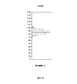
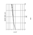
- FIG. 7 is a graph showing vibration characteristics of a crystal oscillator according to a comparative example
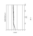
- 4 is a graph showing vibration characteristics of a crystal resonator according to one embodiment
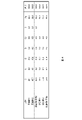
- 4 is a data table showing the composition of substances adhering to the crystal vibrating element
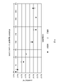
- 4 is a graph showing dynamic viscoelastic properties of an adhesive
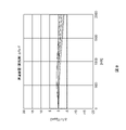
- 4 is a graph showing the correlation between heat treatment time and ESR change rate.
- 10 is a graph showing the rate of change in oscillation frequency of a crystal oscillator according to a comparative example when left at high temperature.
- 5 is a graph showing the rate of change in vibration frequency of the crystal resonator according to the embodiment when left at high temperature.
- 7 is a graph showing the amount of change in ESR in a crystal oscillator according to a comparative example when left at high temperature.
- 4 is a graph showing the amount of change in ESR when the crystal resonator according to the embodiment is left at high temperature. It is a figure for demonstrating the effect
- a crystal oscillator which is an example of a piezoelectric oscillator according to an embodiment of the present invention, will be described below.
- the crystal resonator 1 includes a crystal resonator element 100 that is an example of a piezoelectric resonator element, a cap 200 that is an example of a lid member, and a substrate 300.
- the crystal vibrating element 100 includes a crystal substrate 110, a first excitation electrode 120, and a second excitation electrode .
- the first excitation electrode 120 is formed on the first surface 112 of the crystal substrate 110
- the second excitation electrode 130 is formed on the second surface 114 opposite to the first surface 112 of the crystal substrate 110 .
- the crystal vibrating element 100 has, for example, an AT-cut crystal substrate 110 .
- the crystal substrate 110 is formed by rotating the Y-axis and Z-axis from the Y-axis to the Z-axis direction by 35 degrees and 15 minutes around the X-axis among the X-axis, Y-axis, and Z-axis, which are the crystal axes of the artificial crystal. are the Y'-axis and the Z'-axis, respectively, the surface parallel to the plane specified by the X-axis and the Z'-axis is cut out as the main surface.
- the crystal substrate 110 has a substantially rectangular plate shape, with the Z'-axis direction being the longitudinal direction, the X-axis direction being the lateral direction, and the Y'-axis direction being the thickness direction.
- the piezoelectric substrate according to the present embodiment is not limited to the above configuration.
- an AT-cut crystal substrate having a longitudinal direction parallel to the X-axis direction and a lateral direction parallel to the Z′-axis direction. may be applied, a different cut crystal substrate other than the AT cut may be used, or other piezoelectric materials such as ceramics other than crystal may be applied.
- the first excitation electrode 120 is formed on the first surface 112 of the crystal substrate 110
- the second excitation electrode 130 is formed on the second surface 114 opposite to the first surface 112 of the crystal substrate 110 .
- the first and second excitation electrodes 120 and 130 are a pair of electrodes, and have portions that overlap each other in plan view from the Y'-axis direction.
- the crystal substrate 110 has a connection electrode 124 electrically connected to the first excitation electrode 120 through the extraction electrode 122 and a connection electrode 134 electrically connected to the second excitation electrode 130 through the extraction electrode 132 .
- the extraction electrode 122 extends from the first excitation electrode 120 toward the short side of the crystal substrate 110 in the negative Z′-axis direction on the first surface 112 of the crystal substrate 110 .
- the connection electrode 124 extends in the X-axis direction negative direction from the lead-out electrode 122 on the first surface 112 of the crystal substrate 110 toward the X-axis direction negative direction side of the crystal substrate 110 . , and extends in the positive X-axis direction on the second surface 114 of the crystal substrate 110 .
- the extraction electrode 132 extends from the second excitation electrode 130 on the first surface 112 of the crystal substrate 110 toward the short side of the crystal substrate 110 in the negative Z′-axis direction.
- the connection electrode 134 extends in the positive X-axis direction from the end of the extraction electrode 132 on the negative Z′-axis direction side of the crystal substrate 110 on the first surface 112 of the crystal substrate 110 . It is folded back at the end on the direction side and extends in the X-axis direction negative direction on the first surface 112 of the crystal substrate 110 .
- the connection electrode 124 is electrically connected to the substrate 300 via a conductive adhesive 340
- the connection electrode 134 is electrically connected to the substrate 300 via a conductive adhesive 342 .
- the arrangement and pattern shape of the connection electrodes 124 and 134 and the extraction electrodes 122 and 132 are not limited, and can be changed as appropriate in consideration of electrical connection with other members.
- the substrate 300 includes connection electrodes 320 and 322 formed on the first surface 302 and lead electrodes 320a and 322a drawn from the connection electrodes 320 and 322 toward the outer edge of the first surface 302.
- the connection electrodes 320 and 322 are arranged inside the outer edge of the substrate 300 .
- the crystal oscillator 100 is arranged substantially in the center of the first surface 302 of the substrate 300 .
- connection electrode 124 of the crystal oscillator 100 is connected to the connection electrode 320 via a conductive adhesive 340
- a connection electrode 134 of the crystal oscillator 100 is connected to the connection electrode 322 via a conductive adhesive 342 . It is
- the extraction electrode 320 a is extracted from the connection electrode 320 toward one corner of the substrate 300 , and the extraction electrode 322 a is extracted from the connection electrode 322 toward another corner of the substrate 300 .
- One external electrode 330, 332, 334, 336 is formed at each of the plurality of corner portions.
- the extraction electrode 320a is connected to the external electrode 330, and the extraction electrode 322a is connected to the external electrode 332. As shown in FIG.
- the crystal oscillator 1 By applying an AC voltage between the first excitation electrode 120 and the second excitation electrode 130 of the crystal oscillator 1 via the external electrodes 330 and 332, the crystal oscillator 1 is operated in a predetermined vibration mode such as a thickness-shear vibration mode.
- the crystal substrate 110 is vibrated in vibration mode.
- the cap 200 has side walls 220 vertically erected from the upper surface 210A of the bottom plate 210 .
- the side wall portion 220 has a rectangular annular shape, and its tip portion is joined to the upper surface 300A of the substrate 300 via the joining member 350 .
- the joining member 350 joins the substrate 300 and the cap 200 together.
- Crystal vibrating element 100 is housed in internal space S ⁇ b>1 surrounded by side wall portion 220 of cap 200 and substrate 300 .
- the joining member 350 is provided along the entire circumference of the side wall portion 220 of the cap 200 and is interposed between the tip portion of the side wall portion 220 of the cap 200 and the upper surface 300A of the substrate 300 .
- the joining member 350 is a cured adhesive, and the adhesive contains (A) a polymer material that is solid at room temperature and (B) a solvent with a boiling point of 100° C. or higher.
- the adhesive contains, for example, a polymer epoxy resin that is solid at room temperature as a main agent, an imidazole or amine curing agent as a curing agent, an oxide such as silica as a filler, and a glycol solvent as a high boiling point solvent. including.
- the polymer epoxy resin preferably has a melting point or softening point of 50° C. or higher, for example.
- the polymer epoxy resin preferably has a rigid skeleton.
- the high-molecular epoxy resin preferably has an elastic modulus of 1 GPa or more in a temperature range of 100° C. or higher and 150° C. or lower, and does not have a glass transition point in a temperature range of 150° C. or higher and 200° C. or lower. is preferred.
- the polymer epoxy resin for example, a novolac type epoxy resin, a naphthalene type epoxy resin, or a biphenyl type epoxy resin is used.
- a mixture of these resins may be used as the polymeric epoxy resin.
- glycol solvent for example, ethylene glycol monomethyl ether acetate (boiling point 145° C.) or diethylene glycol monoethyl ether acetate (boiling point 217° C.) is used.
- glycol-based solvent for example, a mixture of these solvents may be used.
- the method of manufacturing the crystal oscillator 1 will be described, particularly focusing on the method of bonding the cap 200 and the substrate 300 using an adhesive.
- the caps 200 are aligned on a sticky tray with the tips of the side wall portions 220 directed upward.
- the side wall portion 220 of the cap 200 is immersed in an adhesive, and the tip of the side wall portion 220 of the cap 200 is coated with the adhesive.
- the adhesive applied to the cap 200 is heated and dried so that the adhesive has no tackiness at room temperature.
- the tip of the side wall portion 220 of the cap 200 is brought into contact with the substrate 300 on which the crystal oscillator 100 is mounted. In this case, by heating the substrate 300 , the adhesive applied to the tip of the side wall portion 220 of the cap 200 recovers its tackiness and is bonded to the substrate 300 .
- the adhesive according to the present embodiment recovers tackiness when heated until the temperature of the adhesive reaches the melting point (for example, about 70° C.). Thereafter, the adhesive is cured by applying pressure and heating while interposing the adhesive between the substrate 300 and the cap 200 . As described above, in the present embodiment, the adhesive is cured after the adhesive is heated to dry the solvent. Cap 200 can be joined.
- FIG. 3A shows the vibration characteristics of the crystal oscillator when using the adhesive according to the comparative example
- FIG. 3B shows the vibration characteristics of the crystal oscillator when using the adhesive according to one embodiment.
- An adhesive according to one embodiment contains a solvent with a boiling point of 100° C. or higher
- an adhesive according to a comparative example contains a solvent with a boiling point of 100° C. or lower.
- FIGS. 3A and 3B shows vibration characteristics of a crystal resonator measured by mounting an 80 MHz crystal resonator element on a substrate.
- the frequency variation of the crystal oscillator when using the adhesive according to the embodiment is similar to the frequency variation of the crystal oscillator when using the adhesive according to the comparative example.
- the adhesive according to one embodiment has a solvent with a higher boiling point than the adhesive according to the comparative example. Therefore, when the adhesive is heated and melted and interposed between the substrate and the cover member, the solvent is difficult to volatilize as outgas from the adhesive, and as a result, the volatilized outgas adheres to the crystal oscillator. Hateful. Therefore, it is assumed that the influence on the vibration characteristics of the crystal oscillator due to the adhesion of the solvent to the crystal oscillator will be reduced.
- FIG. 4 is a data table showing the composition of substances adhering to the crystal oscillator.
- data when using the adhesive according to one embodiment are shown as Examples 1 and 2
- data when using the adhesive according to the comparative example are shown as Comparative Examples 1 and 2. It is shown.
- the data table in FIG. 4 shows the composition of the substance adhering to the crystal vibrating element when using each of the adhesives of Examples 1, 2, Comparative Examples 1, and 2 by X-ray photoelectron spectroscopy (XPS analysis). ) shows the data analyzed by X-ray photoelectron spectroscopy (XPS analysis).
- the carbon (C) content is relatively low compared to Comparative Examples 1 and 2. That is, as described above, the adhesive according to one embodiment is less likely to generate outgassing than the adhesive according to the comparative example, so the content of carbon (C) contained in the outgassing can be reduced. is assumed.
- FIG. 5 is a graph showing the dynamic viscoelastic properties of the adhesive.
- data in the case of using the adhesive according to one embodiment is shown as an example, and data in the case of using the adhesive according to the comparative example are shown as comparative examples 1 and 2.
- FIG. 5 shows data obtained by measuring the change in the elastic modulus of the adhesive when each of the adhesives of Example, Comparative Example 1, and Comparative Example 2 was heated.
- data in the case of using an adhesive containing a polymeric epoxy resin having a rigid skeleton is shown as an example, and an adhesive containing a polymeric epoxy resin having no rigid skeleton was used.
- the data of the case are shown as Comparative Example 1 and Comparative Example 2.
- the elastic modulus tends to be higher in the temperature range of 100 ° C. or higher and 200 ° C. or lower than in Comparative Examples 1 and 2, and the temperature range of 100 ° C. or higher and 150 ° C. or lower
- the elastic modulus is 1 GPa or more in the range.
- there is no glass transition point in the temperature range of 150 ° C. or higher and 200 ° C. or lower whereas in Comparative Examples 1 and 2, the glass transition temperature is in the temperature range of 150 ° C. or higher and 200 ° C. or lower. have.
- the glass transition point is the transition temperature at which the properties of polymer molecules change abruptly, and when the temperature of the adhesive exceeds the temperature corresponding to the glass transition point, the elastic modulus of the adhesive drops sharply.
- FIG. 6 is a graph showing the correlation between the heat treatment time and the change rate of ESR (gas permeability) from the initial state.
- ESR gas permeability
- the rate of change in ESR from the initial state tends to be smaller over the entire period after the start of the heat treatment compared to the comparative example. That is, when the bonding member 350 is formed by curing an adhesive containing a polymer epoxy resin having a rigid skeleton, an adhesive that does not contain a polymer epoxy resin having a rigid skeleton is cured and bonded. In a high-temperature environment, the airtightness of the space between the substrate 300 and the cap 200 sealed by the bonding member 350 is maintained as compared with the case where the member 350 is configured.
- FIG. 7 is a graph showing time-series data of the rate of change of the vibration frequency of the crystal oscillator according to the comparative example in a high-temperature environment.
- the crystal oscillator 1 using an adhesive that does not contain a polymer epoxy resin having a rigid skeleton as the bonding member 350 was left in a high temperature environment of 125° C. for 2000 hours.
- 1 shows the rate of change of the vibration frequency from the initial state of 1.
- graphs are shown superimposed when measuring five samples.
- FIG. 8 is a graph showing time-series data of the rate of change of the vibration frequency in a high-temperature environment in a crystal oscillator according to one embodiment.
- the crystal oscillator 1 using an adhesive containing a polymer epoxy resin having a rigid skeleton as the bonding member 350 was left in a high temperature environment of 125° C. for 2000 hours. It shows the change rate of the vibration frequency from the initial state.
- graphs are shown superimposed when measuring five samples.
- the crystal oscillator initial The rate of change of the vibration frequency from the state tends to be small. That is, in the crystal oscillator according to one embodiment, the reliability of operation of the crystal oscillator in a high-temperature environment is higher than that of the crystal oscillator according to the comparative example.
- FIG. 9 is a graph showing time-series data of the amount of ESR change in a crystal oscillator according to a comparative example in a high-temperature environment.
- the crystal oscillator 1 using an adhesive that does not contain a polymer epoxy resin having a rigid skeleton as the bonding member 350 was left in a high temperature environment of 125° C. for 2000 hours. shows the amount of change in ESR from the initial state.
- graphs are shown superimposed when measuring five samples.
- FIG. 10 is a graph showing time-series data of the amount of ESR change in the crystal oscillator 1 according to one embodiment in a high-temperature environment.
- the crystal oscillator 1 using an adhesive containing a polymer epoxy resin having a rigid skeleton as the bonding member 350 was left in a high temperature environment of 125° C. for 2000 hours. shows the amount of change in ESR from the initial state.
- graphs are shown superimposed when measuring five samples.
- the crystal oscillators of all the five samples are more stable than the crystal oscillator according to the comparative example.
- the amount of change in ESR from the initial state tends to be small. That is, in the crystal oscillator 1 according to the embodiment, the reliability of operation of the crystal oscillator in a high-temperature environment is higher than that of the crystal oscillator according to the comparative example.
- FIG. 11 is a diagram for explaining the action of the crystal oscillator according to the comparative example.
- FIG. 11 shows a top view of a quartz oscillator according to a comparative example from which the cap 200 has been removed after drying the solvent.
- reference numeral "350A” indicates an adhesive
- reference numeral "350B” indicates a broken insulating film
- reference numeral "350C” indicates a fillet discolored due to oxidation of the outer adhesive during curing.
- the adhesive including the fillet spreads to the vicinity of the end surface of the crystal oscillator 1 .
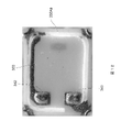
- FIG. 12 is a diagram for explaining the action of the crystal resonator 1 according to one embodiment.
- FIG. 12 shows a top view of the crystal resonator 1 according to one embodiment, from which the cap 200 and the crystal resonator element 100 are removed after drying the solvent.
- the code "350A ⁇ " indicates an adhesive.
- the spread of the adhesive is smaller than in the crystal oscillator 1 according to the comparative example described above, and bleeding of the adhesive is suppressed. .
- an adhesive containing (A) a polymer material that is solid at room temperature and (B) a solvent having a boiling point of 100° C. or higher is heated and melted. It includes a step of interposing between the substrate 300 and the cap 200, and a step of bonding the substrate 300 and the cap 200 with a bonding member 350 having cured adhesive.
- the adhesive is melted by heating to 100° C. or more and spreads between the substrate 300 and the cap 200 , the solvent is prevented from volatilizing as outgassing and adhering to the crystal vibrating element 100 . . Therefore, the reliability of the operation of the crystal resonator 1 can be enhanced.
- (A) is a compound containing a benzene ring having one or more functional groups as the main ingredient. That is, (A) is a compound having a rigid skeleton.
- (A) does not have a glass transition point in the temperature range of 150°C or higher and 200°C or lower.
- the adhesive when the adhesive is heated to a temperature range of 150° C. or higher and 200° C. or lower and is melted and spread wet between the substrate 300 and the cap 200, the shape retention of the adhesive is further enhanced. It can contribute to the further miniaturization of the crystal unit 1 . Moreover, even in a high-temperature environment, the properties of the adhesive are further maintained. Therefore, the heat resistance of the crystal resonator 1 can be further improved.
- a method of manufacturing a piezoelectric vibrator comprising: (A) a polymer material that is solid at room temperature; Provided is a method for manufacturing a piezoelectric vibrator, including the steps of interposing between a cover member and a step of joining the substrate and the cover member with a joining member obtained by curing an adhesive.
- a method for manufacturing a piezoelectric vibrator wherein (A) has a melting point or softening point of 50°C or higher.
- a method for manufacturing a piezoelectric vibrator wherein (A) is a compound containing a benzene ring having one or more functional groups as a main ingredient.
- a method for manufacturing a piezoelectric vibrator wherein (A) is a compound containing a benzene ring having three or more functional groups as a main ingredient.
- (A) provides a method for manufacturing a piezoelectric vibrator that does not have a glass transition point in the temperature range of 150°C or higher and 200°C or lower.
- a method for manufacturing a piezoelectric vibrator wherein (A) is a polymeric epoxy resin.
- a substrate a piezoelectric vibration element mounted on the substrate, a lid member that is bonded to the substrate and seals the piezoelectric vibration element, a bonding member that bonds the substrate and the lid member, wherein the bonding member is a cured adhesive, the adhesive contains (A) a polymer material that is solid at room temperature, and (B) a solvent having a boiling point of 100° C. or higher, and the piezoelectric vibrator is provided.
- (A) provides a piezoelectric vibrator having a melting point or softening point of 50°C or higher.
- a piezoelectric vibrator in which (A) is based on a compound containing a benzene ring having one or more functional groups.
- a piezoelectric vibrator in which (A) is mainly composed of a compound containing a benzene ring having three or more functional groups.
- (A) provides a piezoelectric vibrator that does not have a glass transition point in a temperature range of 150°C or higher and 200°C or lower.
- a piezoelectric vibrator in which (A) is a polymeric epoxy resin.
- the reliability of operation can be enhanced.
Landscapes
- Physics & Mathematics (AREA)
- Acoustics & Sound (AREA)
- Piezo-Electric Or Mechanical Vibrators, Or Delay Or Filter Circuits (AREA)
Abstract
基板と、基板に搭載される圧電振動素子と、基板に接合されて圧電振動素子を封止する蓋部材と、基板と蓋部材とを接合する保持部材と、を備え、保持部材は、接着剤の硬化物であり、接着剤は、(A)常温で固体の高分子材料と、(B)沸点が100℃以上の溶剤と、を含む。
Description
本発明は、圧電振動子および圧電振動子の製造方法に関する。
発振装置や帯域フィルタなどに用いられる基準信号の信号源に、圧電振動子が広く用いられている。例えば、特許文献1には、基板と蓋部材とを接合部材を介して接合し、基板に搭載された圧電振動素子を、基板と蓋部材との間に形成された空間に収容する圧電振動子が開示されている。接合部材は、例えば、接着剤の硬化物である。
しかしながら、従来の技術においては、接着剤の一部の成分が揮発してアウトガスを発生すると、アウトガスが圧電振動素子に付着して圧電振動子の周波数特性に影響を与えるおそれがあった。
本発明は、このような事情に鑑みてなされたものであり、動作の信頼性を高めることができる圧電振動子および圧電振動子の製造方法を提供することを目的とする。
本発明の一側面に係る圧電振動子は、基板と、基板に搭載される圧電振動素子と、基板に接合されて圧電振動素子を封止する蓋部材と、基板と蓋部材とを接合する接合部材と、を備え、接合部材は、接着剤の硬化物であり、接着剤は、(A)常温で固体の高分子材料と、(B)沸点が100℃以上の溶剤と、を含む。
本発明の一側面に係る圧電振動子の製造方法は、(A)常温で固体の高分子材料と、(B)沸点が100℃以上の溶剤とを含む接着剤を加熱して溶融させた状態で基板に塗布する工程と、基板に塗布された前記接着剤に対して蓋部材を接着させる工程と、接着剤を硬化させた接合部材により、基板と蓋部材とを接合する工程と、を含む。
本発明によれば、動作の信頼性を高めることができる。
以下、本発明の一実施形態に係る圧電振動子の一例である水晶振動子について説明する。
図1及び図2に示すように、本実施形態に係る水晶振動子1は、圧電振動素子の一例である水晶振動素子100と、蓋部材の一例であるキャップ200と、基板300とを備える。
水晶振動素子100は、水晶基板110と、第1励振電極120と、第2励振電極130とを含む。第1励振電極120は、水晶基板110の第1面112に形成され、第2励振電極130は、水晶基板110の第1面112とは反対の第2面114に形成されている。
水晶振動素子100は、例えば、ATカットの水晶基板110を有する。水晶基板110は、人工水晶の結晶軸であるX軸、Y軸、Z軸のうち、Y軸及びZ軸をX軸の周りにY軸からZ軸の方向に35度15分回転させた軸をそれぞれY´軸及びZ´軸とした場合、X軸及びZ´軸によって特定される面と平行な面を主面として切り出されたものである。図1に示す例では、水晶基板110は、略矩形板状をなしており、Z´軸方向を長手方向とし、X軸方向を短手方向とし、Y´軸方向を厚さ方向としている。
なお、本実施形態に係る圧電基板は上記構成に限定されるものではなく、例えば、X軸方向に平行な長手方向と、Z´軸方向に平行な短手方向とを有するATカットの水晶基板を適用してもよいし、ATカット以外の異なるカットの水晶基板であってもよいし、又は、水晶以外のセラミックなどのその他の圧電材料を適用してもよい。
第1励振電極120は、水晶基板110の第1面112に形成され、第2励振電極130は、水晶基板110の第1面112とは反対の第2面114に形成されている。第1及び第2励振電極120,130は一対の電極であり、Y´軸方向からの平面視において互いに重なる部分を有している。
水晶基板110は、第1励振電極120に引出電極122を介して電気的に接続された接続電極124と、第2励振電極130に引出電極132を介して電気的に接続された接続電極134とを有している。具体的には、引出電極122は、水晶基板110の第1面112において、第1励振電極120から水晶基板110のZ´軸負方向側の短辺に向かって延びている。接続電極124は、水晶基板110の第1面112において引出電極122における水晶基板110のZ´軸方向負方向側の端部からX軸方向負方向側に延び水晶基板110のX軸負方向側の端部で折り返されて、水晶基板110の第2面114においてX軸方向正方向側に延びている。引出電極132は、水晶基板110の第1面112において、第2励振電極130から水晶基板110のZ´軸方向負方向側の短辺に向かって延びている。接続電極134は、水晶基板110の第1面112において引出電極132における水晶基板110のZ´軸方向負方向側の端部からX軸方向正方向側に延び、水晶基板110のX軸方向正方向側の端部で折り返されて、水晶基板110の第1面112においてX軸方向負方向側に延びている。接続電極124は、導電性接着剤340を介して基板300に電気的に接続され、接続電極134は、導電性接着剤342を介して基板300に電気的に接続されている。なお、本実施形態において、接続電極124,134及び引出電極122,132の配置やパターン形状は限定されるものではなく、他の部材との電気的接続を考慮して適宜変更することができる。
基板300は、第1面302に形成された接続電極320,322と、接続電極320,322から第1面302の外縁に向かって引き出された引出電極320a,322aとを含む。接続電極320,322は、基板300の外縁よりも内側に配置されている。水晶振動素子100は、基板300の第1面302の略中央に配置されている。
接続電極320には、導電性接着剤340を介して水晶振動素子100の接続電極124が接続され、接続電極322には、導電性接着剤342を介して水晶振動素子100の接続電極134が接続されている。
引出電極320aは、接続電極320から基板300のいずれか1つのコーナー部に向かって引き出され、引出電極322aは、接続電極322から基板300の他の1つのコーナー部に向かって引き出されている。複数のコーナー部の各々には、外部電極330,332,334,336が一つずつ形成されている。図1に示す例では、引出電極320aが外部電極330に接続され、引出電極322aが外部電極332に接続されている。
水晶振動子1は、外部電極330,332を介して、水晶振動子1における第1励振電極120及び第2励振電極130の間に交流電圧を印加することにより、厚みすべり振動モードなどの所定の振動モードで水晶基板110を振動させる。
キャップ200は、底板210の上面210Aから垂直に立設された側壁部220を有している。側壁部220は、矩形環状をなしており、その先端部が接合部材350を介して基板300の上面300Aに接合されている。
接合部材350は、基板300とキャップ200とを接合している。水晶振動素子100は、キャップ200の側壁部220と基板300とによって囲まれた内部空間S1に収容されている。接合部材350は、キャップ200の側壁部220の全周に亘って設けられており、キャップ200の側壁部220の先端部と基板300の上面300Aとの間に介在している。
接合部材350は、接着剤の硬化物であり、接着剤は、(A)常温で固体の高分子材料と、(B)沸点が100℃以上の溶剤とを含む。接着剤は、例えば、主剤として常温で固形の高分子エポキシ系樹脂を含み、硬化剤としてイミダゾール系またはアミン系硬化剤を含み、フィラーとしてシリカなどの酸化物を含み、高沸点溶剤としてグリコール系溶剤を含む。高分子エポキシ系樹脂は、例えば、融点または軟化点が50℃以上であることが好ましい。高分子エポキシ系樹脂は、剛直な骨格を有することが好ましく、例えば、一以上の官能基を有するベンゼン環を含む化合物であることが好ましく、さらには、三以上の官能基を有するベンゼン環を含む化合物であることが好ましい。高分子エポキシ系樹脂は、例えば、100℃以上150℃以下の温度範囲において弾性率が1GPa以上であることが好ましく、さらには、150℃以上200℃以下の温度範囲においてガラス転移点を有さないことが好ましい。高分子エポキシ系樹脂としては、例えば、ノボラック型エポキシ樹脂、ナフタレン型エポキシ樹脂、または、ビフェニル型エポキシ樹脂が用いられる。高分子エポキシ系樹脂としては、例えば、これらの樹脂の混合物が用いられてもよい。グリコール系溶剤としては、例えば、エチレングリコールモノメチルエーテルアセテート(沸点145℃)、または、ジエチレングリコールモノエチルエーテルアセテート(沸点217℃)が用いられる。グリコール系溶剤としては、例えば、これらの溶剤の混合物が用いられてもよい。
次に、水晶振動子1の製造方法について、特に、接着剤を用いたキャップ200と基板300との接合方法に着目して説明する。
キャップ200と基板300とを接合する際には、まず、粘着性のあるトレイに、側壁部220の先端を上方に向けた状態でキャップ200を整列させる。次に、キャップ200の側壁部220を接着剤に浸漬させ、キャップ200の側壁部220の先端に接着剤を塗布する。次に、キャップ200に塗布された接着剤を加熱して乾燥させ、常温では接着剤のタック性が無い状態とする。次に、水晶振動素子100が搭載された基板300に対してキャップ200の側壁部220の先端を当接させる。この場合、基板300を加熱することで、キャップ200の側壁部220の先端に塗布された接着剤はタック性を回復し、基板300に接合される。本実施形態に係る接着剤は、接着剤の温度が融点(例えば、約70℃)に達するまで加熱されると、タック性を回復する。その後、基板300とキャップ200との間に接着剤を介在させた状態で、接着剤を加圧しつつ加熱することで接着剤を硬化させる。このように、本実施形態では、接着剤を加熱して溶剤を乾燥させた後に接着剤の硬化を行うため、基板300とキャップ200との間での接着剤の滲みを抑えつつ、基板300とキャップ200とを接合することができる。
次に、接着剤を用いた場合の水晶振動子の振動特性について説明する。
図3Aは、比較例に係る接着剤を用いた場合の水晶振動子の振動特性を示し、図3Bは、一実施形態に係る接着剤を用いた場合の水晶振動子の振動特性を示す。一実施形態に係る接着剤は、沸点が100℃以上の溶剤を含み、比較例に係る接着剤は、沸点が100℃以下の溶剤を含む。図3A及び図3Bの各々においては、80MHzの水晶振動素子を基板に搭載して測定された水晶振動子の振動特性が示されている。
図3A及び図3Bを比較して示すように、一実施形態に係る接着剤を用いた場合の水晶振動子の周波数ばらつきは、比較例に係る接着剤を用いた場合の水晶振動子の周波数ばらつきに比して小さい。すなわち、一実施形態に係る接着剤は、比較例に係る接着剤に比して、溶剤の沸点が高い。そのため、接着剤を加熱して溶融させた状態で基板と蓋部材との間に介在させた場合、接着剤から溶媒がアウトガスとして揮発しにくく、結果として、揮発したアウトガスが水晶振動素子に付着しにくい。したがって、水晶振動素子に対する溶媒に付着に起因して、水晶振動子の振動特性に与える影響が小さくなることが想定される。
図4は、水晶振動素子に付着した物質の組成を示すデータテーブルである。この例では、一実施形態に係る接着剤を用いた場合のデータが実施例1、実施例2として示され、比較例に係る接着剤を用いた場合のデータが比較例1、比較例2として示されている。図4におけるデータテーブルは、実施例1、実施例2、比較例1、比較例2の各々の接着剤を用いた場合における水晶振動素子に付着した物質の組成をX線光電子分光法(XPS分析)により分析したデータを示す。
図4に示すように、実施例1及び実施例2においては、比較例1及び比較例2に比して、炭素(C)の含有量が相対的に少ない。すなわち、上述のように、一実施形態に係る接着剤は、比較例に係る接着剤に比して、アウトガスが発生しにくいため、アウトガスに含まれる炭素(C)の含有量が少なくなることが想定される。
図5は、接着剤の動的粘弾性特性を示すグラフである。この例では、一実施形態に係る接着剤を用いた場合のデータが実施例として示され、比較例に係る接着剤を用いた場合のデータが比較例1、比較例2として示されている。図5においては、実施例、比較例1、比較例2の各々の接着剤を加熱した場合の接着剤の弾性率の変化を測定したデータを示す。この例では、剛直な骨格を有する高分子エポキシ系樹脂を含む接着剤を用いた場合のデータが実施例として示され、剛直な骨格を有さない高分子エポキシ系樹脂を含む接着剤を用いた場合のデータが比較例1、比較例2として示されている。
図5に示すように、実施例においては、比較例1及び比較例2に比して、100℃以上200℃以下の温度範囲において弾性率が高い傾向にあり、100℃以上150℃以下の温度範囲において弾性率が1GPa以上である。実施例においては、150℃以上200℃以下の温度範囲においてガラス転移点を有していないのに対し、比較例1及び比較例2においては、150℃以上200℃以下の温度範囲においてガラス転移点を有している。ガラス転移点は、ポリマー分子の特性が急激に変わる転移温度であり、接着剤の温度がガラス転移点に相当する温度を上回ると、接着剤の弾性率が急峻に低下する。
図6は、加熱処理時間と初期状態からのESR(気体透過性)の変化率との相関関係を示すグラフである。この例では、剛直な骨格を有する高分子エポキシ系樹脂を含む接着剤を用いた場合のデータが実施例として示され、剛直な骨格を有さない高分子エポキシ系樹脂を含む接着剤を用いた場合のデータが比較例として示されている。図6においては、実施例、比較例の各々の接着剤を硬化させて接合部材350として用いた場合の加熱処理を開始してからのESRの変化率の時系列データを示す。
図6に示すように、実施例においては、比較例に比して、加熱処理を開始してからの全体に亘って、初期状態からのESRの変化率が小さくなる傾向にある。すなわち、剛直な骨格を有する高分子エポキシ系樹脂を含む接着剤を硬化させて接合部材350を構成した場合には、剛直な骨格を有する高分子エポキシ系樹脂を含まない接着剤を硬化させて接合部材350を構成した場合に比して、高温環境下において、接合部材350により封止された基板300とキャップ200との間の空間の気密性が保たれる。
図7は、比較例に係る水晶振動子における高温環境下での振動周波数の変化率の時系列データを示すグラフである。この例では、例えば、剛直な骨格を有する高分子エポキシ系樹脂を含まない接着剤を接合部材350として用いた水晶振動子1を、125℃の高温環境下に2000時間放置したときの水晶振動子1の初期状態からの振動周波数の変化率を示している。図7においては、5個のサンプルを測定対象としたときのグラフが重ねて示されている。
図8は、一実施形態に係る水晶振動子における高温環境下での振動周波数の変化率の時系列データを示すグラフである。この例では、例えば、剛直な骨格を有する高分子エポキシ系樹脂を含む接着剤を接合部材350として用いた水晶振動子1を、125℃の高温環境下に2000時間放置したときの水晶振動子の初期状態からの振動周波数の変化率を示している。図8においては、5個のサンプルを測定対象としたときのグラフが重ねて示されている。
図7及び図8を比較して示すように、一実施形態に係る水晶振動子においては、比較例に係る水晶振動子に比して、5個のサンプルのいずれについても、水晶振動子の初期状態からの振動周波数の変化率が小さくなる傾向にある。すなわち、一実施形態に係る水晶振動子においては、比較例に係る水晶振動子に比して、高温環境下における水晶振動子の動作の信頼性が高くなる。
図9は、比較例に係る水晶振動子における高温環境下でのESRの変化量の時系列データを示すグラフである。この例では、例えば、剛直な骨格を有する高分子エポキシ系樹脂を含まない接着剤を接合部材350として用いた水晶振動子1を、125℃の高温環境下に2000時間放置したときの水晶振動子の初期状態からのESRの変化量を示している。図9においては、5個のサンプルを測定対象としたときのグラフが重ねて示されている。
図10は、一実施形態に係る水晶振動子1における高温環境下でのESRの変化量の時系列データを示すグラフである。この例では、例えば、剛直な骨格を有する高分子エポキシ系樹脂を含む接着剤を接合部材350として用いた水晶振動子1を、125℃の高温環境下に2000時間放置したときの水晶振動子1の初期状態からのESRの変化量を示している。図10においては、5個のサンプルを測定対象としたときのグラフが重ねて示されている。
図9及び図10を比較して示すように、一実施形態に係る水晶振動子1においては、比較例に係る水晶振動子に比して、5個のサンプルのいずれについても、水晶振動子の初期状態からのESRの変化量が小さくなる傾向にある。すなわち、一実施形態に係る水晶振動子1においては、比較例に係る水晶振動子に比して、高温環境下における水晶振動子の動作の信頼性が高くなる。
図11は、比較例に係る水晶振動子の作用を説明するための図である。図11は、比較例に係る水晶振動子から溶剤の乾燥後にキャップ200が除かれた状態を上方から見た図を示す。図11において、符号「350A」は接着剤を示し、符号「350B」は破断した絶縁膜を示し、符号「350C」は外側の接着剤が硬化時に酸化して変色したフィレットを示す。同図に示すように、比較例に係る水晶振動子1においては、フィレットを含む接着剤が水晶振動子1の端面の近傍まで広がっている。
図12は、一実施形態に係る水晶振動子1の作用を説明するための図である。図12は、一実施形態に係る水晶振動子1から溶剤の乾燥後にキャップ200および水晶振動素子100が除かれた状態を上方から見た図を示す。図12において、符号「350Aα」は接着剤を示す。同図に示すように、一実施形態に係る水晶振動子1においては、上述した比較例に係る水晶振動子1に比して、接着剤の広がりが小さく、接着剤のにじみが抑えられている。
一実施形態に係る水晶振動子1の製造方法は、(A)常温で固体の高分子材料と、(B)沸点が100℃以上の溶剤とを含む接着剤を加熱して溶融させた状態で基板300とキャップ200との間に介在させる工程と、接着剤を硬化させた接合部材350により、基板300とキャップ200とを接合する工程と、を含む。これにより、接着剤を100℃以上に加熱して溶融させた状態で基板300とキャップ200との間に濡れ広がらせる際、溶剤がアウトガスとして揮発し、水晶振動素子100に付着することが抑えられる。したがって、水晶振動子1の動作の信頼性を高めることができる。
また、一実施形態に係る水晶振動子1の製造方法において、(A)は、一以上の官能基を有するベンゼン環を含む化合物が主剤である。すなわち、(A)は、剛直な骨格を有する化合物である。これにより、接着剤の形状保持性が高まるため、基板300とキャップ200との間に接着剤を介在させた状態で接着剤を硬化させる際、接着剤が基板300とキャップ200との間から滲みだしにくい。したがって、接着剤と水晶振動素子100との間のクリアランスを小さくすることができ、水晶振動子1の小型化に寄与することができる。また、高温環境下であっても、接着剤の特性が維持される。したがって、水晶振動子1の耐熱性を高めることができる。
また、一実施形態に係る水晶振動子1の製造方法において、(A)は、150℃以上200℃以下の温度範囲において、ガラス転移点を有さない。これにより、接着剤を150℃以上200℃以下の温度範囲まで加熱して溶融させた状態で基板300とキャップ200との間に濡れ広がらせる際、接着剤の形状保持性がより一層高まるため、水晶振動子1のさらなる小型化に寄与することができる。また、高温環境下であっても、接着剤の特性がより一層維持される。したがって、水晶振動子1の耐熱性をさらに高めることができる。
以下に、本発明の実施形態の一部又は全部を付記し、その効果について説明する。なお、本発明は以下の付記に限定されるものではない。
本発明の一態様によれば、基板と、基板に搭載される圧電振動素子と、基板に接合されて圧電振動素子を封止する蓋部材と、基板と蓋部材とを接合する接合部材と、を備える圧電振動子の製造方法であって、(A)常温で固体の高分子材料と、(B)沸点が100℃以上の溶剤とを含む接着剤を加熱して溶融させた状態で基板と蓋部材との間に介在させる工程と、接着剤を硬化させた接合部材により、基板と蓋部材とを接合する工程と、を含む、圧電振動子の製造方法が提供される。
本発明の一態様によれば、(A)は、融点または軟化点が50℃以上である、圧電振動子の製造方法が提供される。
本発明の一態様によれば、(A)は、一以上の官能基を有するベンゼン環を含む化合物が主剤である、圧電振動子の製造方法が提供される。
本発明の一態様によれば、(A)は、三以上の官能基を有するベンゼン環を含む化合物が主剤である、圧電振動子の製造方法が提供される。
本発明の一態様によれば、(A)は、150℃以上200℃以下の温度範囲において、ガラス転移点を有さない、圧電振動子の製造方法が提供される。
本発明の一態様によれば、(A)は、高分子エポキシ系樹脂である、圧電振動子の製造方法が提供される。
本発明の一態様によれば、基板と、基板に搭載される圧電振動素子と、基板に接合されて圧電振動素子を封止する蓋部材と、基板と蓋部材とを接合する接合部材と、を備え、接合部材は、接着剤の硬化物であり、接着剤は、(A)常温で固体の高分子材料と、(B)沸点が100℃以上の溶剤と、を含む、圧電振動子が提供される。
本発明の一態様によれば、(A)は、融点または軟化点が50℃以上である、圧電振動子が提供される。
本発明の一態様によれば、(A)は、一以上の官能基を有するベンゼン環を含む化合物が主剤である、圧電振動子が提供される。
本発明の一態様によれば、(A)は、三以上の官能基を有するベンゼン環を含む化合物が主剤である、圧電振動子が提供される。
本発明の一態様によれば、(A)は、150℃以上200℃以下の温度範囲において、ガラス転移点を有さない、圧電振動子が提供される。
本発明の一態様によれば、(A)は、高分子エポキシ系樹脂である、圧電振動子が提供される。
以上説明したように、本発明の一態様によれば、動作の信頼性を高めることができる。
なお、以上説明した各実施形態は、本発明の理解を容易にするためのものであり、本発明を限定して解釈するためのものではない。本発明は、その趣旨を逸脱することなく、変更/改良され得るとともに、本発明にはその等価物も含まれる。即ち、各実施形態に当業者が適宜設計変更を加えたものも、本発明の特徴を備えている限り、本発明の範囲に包含される。例えば、各実施形態が備える各要素及びその配置、材料、条件、形状、サイズなどは、例示したものに限定されるわけではなく適宜変更することができる。また、各実施形態は例示であり、異なる実施形態で示した構成の部分的な置換又は組み合わせが可能であることは言うまでもなく、これらも本発明の特徴を含む限り本発明の範囲に包含される。
1…水晶振動子、100…水晶振動素子、110…水晶基板、120…第1励振電極、130…第2励振電極、200…キャップ、300…基板、320,322…接続電極、320a,322a…引出電極、340,342…導電性接着剤、350…接合部材。
Claims (12)
- 基板と、
前記基板に搭載される圧電振動素子と、
前記基板に接合されて前記圧電振動素子を封止する蓋部材と、
前記基板と前記蓋部材とを接合する接合部材と、
を備える圧電振動子の製造方法であって、
(A)常温で固体の高分子材料と、(B)沸点が100℃以上の溶剤とを含む接着剤を加熱して溶融させた状態で前記基板と前記蓋部材との間に介在させる工程と、
前記接着剤を硬化させた前記接合部材により、前記基板と前記蓋部材とを接合する工程と、
を含む、
圧電振動子の製造方法。 - 前記(A)は、融点または軟化点が50℃以上である、
請求項1に記載の圧電振動子の製造方法。 - 前記(A)は、一以上の官能基を有するベンゼン環を含む化合物が主剤である、
請求項1または2に記載の圧電振動子の製造方法。 - 前記(A)は、三以上の官能基を有するベンゼン環を含む化合物が主剤である、
請求項3に記載の圧電振動子の製造方法。 - 前記(A)は、150℃以上200℃以下の温度範囲において、ガラス転移点を有さない、
請求項3または4に記載の圧電振動子の製造方法。 - 前記(A)は、高分子エポキシ系樹脂である、
請求項5に記載の圧電振動子の製造方法。 - 基板と、
前記基板に搭載される圧電振動素子と、
前記基板に接合されて前記圧電振動素子を封止する蓋部材と、
前記基板と前記蓋部材とを接合する接合部材と、
を備え、
前記接合部材は、接着剤の硬化物であり、
前記接着剤は、
(A)常温で固体の高分子材料と、
(B)沸点が100℃以上の溶剤と、
を含む、
圧電振動子。 - 前記(A)は、融点または軟化点が50℃以上である、
請求項7に記載の圧電振動子。 - 前記(A)は、一以上の官能基を有するベンゼン環を含む化合物が主剤である、
請求項7または8に記載の圧電振動子。 - 前記(A)は、三以上の官能基を有するベンゼン環を含む化合物が主剤である、
請求項9に記載の圧電振動子。 - 前記(A)は、150℃以上200℃以下の温度範囲において、ガラス転移点を有さない、
請求項9または10に記載の圧電振動子。 - 前記(A)は、高分子エポキシ系樹脂である、
請求項11に記載の圧電振動子。
Priority Applications (1)
| Application Number | Priority Date | Filing Date | Title |
|---|---|---|---|
| JP2023531348A JP7521703B2 (ja) | 2021-06-29 | 2022-01-11 | 圧電振動子および圧電振動子の製造方法 |
Applications Claiming Priority (2)
| Application Number | Priority Date | Filing Date | Title |
|---|---|---|---|
| JP2021108012 | 2021-06-29 | ||
| JP2021-108012 | 2021-06-29 |
Publications (1)
| Publication Number | Publication Date |
|---|---|
| WO2023276201A1 true WO2023276201A1 (ja) | 2023-01-05 |
Family
ID=84691085
Family Applications (1)
| Application Number | Title | Priority Date | Filing Date |
|---|---|---|---|
| PCT/JP2022/000453 Ceased WO2023276201A1 (ja) | 2021-06-29 | 2022-01-11 | 圧電振動子および圧電振動子の製造方法 |
Country Status (2)
| Country | Link |
|---|---|
| JP (1) | JP7521703B2 (ja) |
| WO (1) | WO2023276201A1 (ja) |
Cited By (3)
| Publication number | Priority date | Publication date | Assignee | Title |
|---|---|---|---|---|
| JP7743655B1 (ja) | 2024-04-26 | 2025-09-24 | 日本電波工業株式会社 | 温度センサ内蔵型の水晶振動子 |
| JP7780679B2 (ja) | 2024-04-26 | 2025-12-04 | 日本電波工業株式会社 | 水晶振動子 |
| WO2025258357A1 (ja) * | 2024-06-13 | 2025-12-18 | 株式会社村田製作所 | 基板及び圧電振動子 |
Citations (2)
| Publication number | Priority date | Publication date | Assignee | Title |
|---|---|---|---|---|
| JP2009231605A (ja) * | 2008-03-24 | 2009-10-08 | Sekisui Chem Co Ltd | 接着剤及び接合体の製造方法 |
| WO2019065519A1 (ja) * | 2017-09-27 | 2019-04-04 | 株式会社村田製作所 | 圧電振動子及び圧電振動子の製造方法 |
Family Cites Families (3)
| Publication number | Priority date | Publication date | Assignee | Title |
|---|---|---|---|---|
| JPH06140868A (ja) * | 1992-10-28 | 1994-05-20 | Murata Mfg Co Ltd | チップ型圧電共振子 |
| CN113396056B (zh) | 2019-03-29 | 2024-05-14 | 太阳控股株式会社 | 中空器件用干膜、固化物和电子部件 |
| CN112953430B (zh) | 2021-01-26 | 2025-06-17 | 广东佛智芯微电子技术研究有限公司 | 一种基于玻璃基板的滤波器封装方法及其封装结构 |
-
2022
- 2022-01-11 JP JP2023531348A patent/JP7521703B2/ja active Active
- 2022-01-11 WO PCT/JP2022/000453 patent/WO2023276201A1/ja not_active Ceased
Patent Citations (2)
| Publication number | Priority date | Publication date | Assignee | Title |
|---|---|---|---|---|
| JP2009231605A (ja) * | 2008-03-24 | 2009-10-08 | Sekisui Chem Co Ltd | 接着剤及び接合体の製造方法 |
| WO2019065519A1 (ja) * | 2017-09-27 | 2019-04-04 | 株式会社村田製作所 | 圧電振動子及び圧電振動子の製造方法 |
Cited By (4)
| Publication number | Priority date | Publication date | Assignee | Title |
|---|---|---|---|---|
| JP7743655B1 (ja) | 2024-04-26 | 2025-09-24 | 日本電波工業株式会社 | 温度センサ内蔵型の水晶振動子 |
| JP2025168235A (ja) * | 2024-04-26 | 2025-11-07 | 日本電波工業株式会社 | 温度センサ内蔵型の水晶振動子 |
| JP7780679B2 (ja) | 2024-04-26 | 2025-12-04 | 日本電波工業株式会社 | 水晶振動子 |
| WO2025258357A1 (ja) * | 2024-06-13 | 2025-12-18 | 株式会社村田製作所 | 基板及び圧電振動子 |
Also Published As
| Publication number | Publication date |
|---|---|
| JP7521703B2 (ja) | 2024-07-24 |
| JPWO2023276201A1 (ja) | 2023-01-05 |
Similar Documents
| Publication | Publication Date | Title |
|---|---|---|
| WO2023276201A1 (ja) | 圧電振動子および圧電振動子の製造方法 | |
| US8476811B2 (en) | Piezoelectric device with tuning-fork type piezoelectric vibrating piece | |
| JP4990047B2 (ja) | 圧電振動片及び圧電デバイス | |
| CN102694524B (zh) | 振动元件及其频率稳定方法、振子及其制造方法和振荡器 | |
| CN102857186A (zh) | 压电元件以及压电元件的制造方法 | |
| CN111108688B (zh) | 压电振子以及压电振子的制造方法 | |
| JP2012186709A (ja) | 圧電振動片及び圧電デバイス | |
| JP5148659B2 (ja) | 圧電デバイス | |
| JP4815976B2 (ja) | 水晶振動デバイスの製造方法 | |
| JP6607408B2 (ja) | 圧電振動部品及びその製造方法 | |
| US8823247B2 (en) | Piezoelectric vibrating devices including respective packages in which castellations include respective connecting electrodes | |
| CN107615652A (zh) | 压电振动元件搭载用基板以及压电振子及其制造方法 | |
| JP6537029B2 (ja) | 水晶振動子及びその製造方法 | |
| JP7606165B2 (ja) | 圧電振動素子、圧電振動子、及び圧電発振器 | |
| JP6179681B2 (ja) | 圧電振動部品の製造方法 | |
| JPH09181558A (ja) | 圧電素子及び樹脂封止型圧電部品 | |
| JP2013172369A (ja) | 圧電デバイス及び圧電デバイスの製造方法 | |
| JP3164891B2 (ja) | 水晶振動子とその製造方法 | |
| CN101248579A (zh) | 压电谐振元件以及采用该元件的压电谐振装置 | |
| JPH03175713A (ja) | 圧電共振子とその製造方法 | |
| JP2003197799A (ja) | 電子部品 | |
| JP2000106516A (ja) | 圧電共振子 | |
| JP4890913B2 (ja) | 圧電振動子の製造方法 | |
| JPS6011486B2 (ja) | 水晶振動子 | |
| JPH10190400A (ja) | 圧電共振部品と製造方法 |
Legal Events
| Date | Code | Title | Description |
|---|---|---|---|
| 121 | Ep: the epo has been informed by wipo that ep was designated in this application |
Ref document number: 22832369 Country of ref document: EP Kind code of ref document: A1 |
|
| WWE | Wipo information: entry into national phase |
Ref document number: 2023531348 Country of ref document: JP |
|
| NENP | Non-entry into the national phase |
Ref country code: DE |
|
| 122 | Ep: pct application non-entry in european phase |
Ref document number: 22832369 Country of ref document: EP Kind code of ref document: A1 |