WO2023248897A1 - 電子打楽器および打音の減音方法 - Google Patents
電子打楽器および打音の減音方法 Download PDFInfo
- Publication number
- WO2023248897A1 WO2023248897A1 PCT/JP2023/022108 JP2023022108W WO2023248897A1 WO 2023248897 A1 WO2023248897 A1 WO 2023248897A1 JP 2023022108 W JP2023022108 W JP 2023022108W WO 2023248897 A1 WO2023248897 A1 WO 2023248897A1
- Authority
- WO
- WIPO (PCT)
- Prior art keywords
- head
- elastic body
- frame
- percussion instrument
- electronic percussion
- Prior art date
- Legal status (The legal status is an assumption and is not a legal conclusion. Google has not performed a legal analysis and makes no representation as to the accuracy of the status listed.)
- Ceased
Links
Images





Classifications
-
- G—PHYSICS
- G10—MUSICAL INSTRUMENTS; ACOUSTICS
- G10D—STRINGED MUSICAL INSTRUMENTS; WIND MUSICAL INSTRUMENTS; ACCORDIONS OR CONCERTINAS; PERCUSSION MUSICAL INSTRUMENTS; AEOLIAN HARPS; SINGING-FLAME MUSICAL INSTRUMENTS; MUSICAL INSTRUMENTS NOT OTHERWISE PROVIDED FOR
- G10D13/00—Percussion musical instruments; Details or accessories therefor
- G10D13/10—Details of, or accessories for, percussion musical instruments
- G10D13/26—Mechanical details of electronic drums
-
- G—PHYSICS
- G10—MUSICAL INSTRUMENTS; ACOUSTICS
- G10D—STRINGED MUSICAL INSTRUMENTS; WIND MUSICAL INSTRUMENTS; ACCORDIONS OR CONCERTINAS; PERCUSSION MUSICAL INSTRUMENTS; AEOLIAN HARPS; SINGING-FLAME MUSICAL INSTRUMENTS; MUSICAL INSTRUMENTS NOT OTHERWISE PROVIDED FOR
- G10D13/00—Percussion musical instruments; Details or accessories therefor
- G10D13/01—General design of percussion musical instruments
- G10D13/02—Drums; Tambourines with drumheads
-
- G—PHYSICS
- G10—MUSICAL INSTRUMENTS; ACOUSTICS
- G10D—STRINGED MUSICAL INSTRUMENTS; WIND MUSICAL INSTRUMENTS; ACCORDIONS OR CONCERTINAS; PERCUSSION MUSICAL INSTRUMENTS; AEOLIAN HARPS; SINGING-FLAME MUSICAL INSTRUMENTS; MUSICAL INSTRUMENTS NOT OTHERWISE PROVIDED FOR
- G10D13/00—Percussion musical instruments; Details or accessories therefor
- G10D13/10—Details of, or accessories for, percussion musical instruments
-
- G—PHYSICS
- G10—MUSICAL INSTRUMENTS; ACOUSTICS
- G10D—STRINGED MUSICAL INSTRUMENTS; WIND MUSICAL INSTRUMENTS; ACCORDIONS OR CONCERTINAS; PERCUSSION MUSICAL INSTRUMENTS; AEOLIAN HARPS; SINGING-FLAME MUSICAL INSTRUMENTS; MUSICAL INSTRUMENTS NOT OTHERWISE PROVIDED FOR
- G10D13/00—Percussion musical instruments; Details or accessories therefor
- G10D13/10—Details of, or accessories for, percussion musical instruments
- G10D13/14—Mutes or dampers
-
- G—PHYSICS
- G10—MUSICAL INSTRUMENTS; ACOUSTICS
- G10D—STRINGED MUSICAL INSTRUMENTS; WIND MUSICAL INSTRUMENTS; ACCORDIONS OR CONCERTINAS; PERCUSSION MUSICAL INSTRUMENTS; AEOLIAN HARPS; SINGING-FLAME MUSICAL INSTRUMENTS; MUSICAL INSTRUMENTS NOT OTHERWISE PROVIDED FOR
- G10D13/00—Percussion musical instruments; Details or accessories therefor
- G10D13/10—Details of, or accessories for, percussion musical instruments
- G10D13/20—Drumheads
-
- G—PHYSICS
- G10—MUSICAL INSTRUMENTS; ACOUSTICS
- G10H—ELECTROPHONIC MUSICAL INSTRUMENTS; INSTRUMENTS IN WHICH THE TONES ARE GENERATED BY ELECTROMECHANICAL MEANS OR ELECTRONIC GENERATORS, OR IN WHICH THE TONES ARE SYNTHESISED FROM A DATA STORE
- G10H1/00—Details of electrophonic musical instruments
Definitions
- Patent Document 1 describes a head member 11 (head), a shock absorbing member 22 (first elastic body) made of sponge disposed below the head member 11, and a support plate that supports the shock absorbing member 22. 21 (support member) and a vibration detection sensor 51 (first sensor) bonded to the lower surface of the support plate 21.
- JP2001-142459A (for example, paragraphs 0024,0032, Figures 4 and 6)
- the electronic percussion instrument of the present invention includes a membrane-like head, a first elastic body disposed below the head and absorbing vibrations of the head when the head is hit, and a first
- the first elastic body includes a support member that supports an elastic body, and a first sensor that is attached to the support member and detects the vibration of the impact on the head, and the first elastic body has a plurality of through holes connecting the upper and lower surfaces of the first elastic body. Equipped with a hole.
- the hitting sound reduction method of the present invention includes a membrane head, a first elastic body disposed below the head, a support member supporting the first elastic body, and a method attached to the support member,
- a method for reducing percussion sounds in an electronic percussion instrument comprising: a first sensor that detects vibrations caused by impact on the head; By absorbing the vibration of the head with the first elastic body, the sound of hitting the head is reduced.
- FIG. 6(d) is a cross-sectional view of the rim showing a fourth modification
- (e) is a cross-sectional view of the rim showing a fifth modification
- FIG. 3D is a cross-sectional view of the rim
- FIG. 3D is a cross-sectional view of the rim showing a tenth modification
- FIG. It is a sectional view of the rim showing a twelfth modification.
- It is an exploded perspective view of the electronic percussion instrument in a 2nd embodiment. It is a partially enlarged sectional view of an electronic percussion instrument. It is a partially enlarged sectional view of an electronic percussion instrument.
- FIG. 7 It is an exploded perspective view of an electronic percussion instrument, a rod, and a support.
- (a) is a partially enlarged sectional view of the case taken along line IXa-IXa in FIG. 7, and
- (b) is a partially enlarged bottom view of the case as viewed in the direction of arrow IXb in FIG. 9(a).
- 12 is a partially enlarged sectional view of the electronic percussion instrument taken along line XII-XII in FIG. 11.
- FIG. 1 is an exploded perspective view of an electronic percussion instrument 100 according to the first embodiment
- FIG. 2 is a partially enlarged sectional view of the electronic percussion instrument 100. Note that FIG. 2 shows a cross section taken along a plane along the central axis of the disk-shaped head 1.
- the electronic percussion instrument 100 is a percussion instrument that imitates an acoustic drum.
- the electronic percussion instrument 100 includes a membrane head 1 whose upper surface serves as a striking surface.
- the head 1 is formed into a disk shape using a mesh made of woven synthetic fibers, and an annular head frame 10 is fixed to the outer edge of the head 1.
- the head frame 10 is fixed to the body 2 of the electronic percussion instrument 100.
- the body portion 2 includes a disk-shaped support portion 20 for supporting an elastic body 3, which will be described later, and a support wall 21 for supporting the head 1 projects upward from the outer edge of the support portion 20.
- a bottom wall 22 for fixing the head frame 10 extends outward from the lower part of the support wall 21, and an outer peripheral wall 23 projects upward from the outer edge of the bottom wall 22.
- Each of these walls 21, 22, 23 is continuous in the circumferential direction, and the head frame 10 is accommodated in a space surrounded by each wall 21, 22, 23.
- the support portion 20 and the walls 21, 22, 23 are integrally formed using a resin material, but for example, the support portion 20 and the walls 21, 22, 23 may be formed separately from each other.
- a structure in which the portion 20 is fixed to the inner circumferential surface of the support wall 21 may also be used.
- the bottom wall 22 has a plurality of (six in this embodiment) female threaded holes 24 arranged at equal intervals in the circumferential direction, and the head frame 10 has a plurality of insertion holes at positions corresponding to the female threaded holes 24. 11 is formed.
- the head frame 10 With the head 1 placed on the support wall 21, by screwing the bolt B1 (see FIG. 2) inserted into the insertion hole 11 of the head frame 10 into the female threaded hole 24, the head frame 10 is pulled downward, and the head Tension is applied to 1.
- a state in which tension is applied to the head 1 and before the head 1 is struck will be simply referred to as a "state before striking.”
- the elastic body 3 includes a polygonal (hexagonal in this embodiment) central elastic body 30 disposed at the center, and a plurality of (in this embodiment, three) central elastic bodies 30 surrounding the central elastic body 30. It is composed of a peripheral elastic body 31. By dividing the elastic body 3 into the central elastic body 30 and the peripheral elastic body 31, the mold for molding each of the elastic bodies 30 and 31 can be downsized.
- the elastic body 3 When the plurality of peripheral elastic bodies 31 are arranged around the central elastic body 30, the elastic body 3 is formed into a disk shape as a whole.
- the diameter of this disk-shaped elastic body 3 is the same as or slightly smaller than the inner diameter of the support wall 21.
- a sensor support member 4 (see FIG. 2) is fixed to the support portion 20 that supports the elastic body 3.
- the sensor support member 4 is formed into a bowl shape including a disk-shaped sensor support part 40 to which the head sensor S1 is attached, and a wall part 41 that projects upward from the outer edge of the sensor support part 40.
- a plurality of female screw holes (not shown) arranged in the circumferential direction are formed on the upper surface of the wall portion 41, and a plurality of female screw holes (not shown) are formed in the support portion 20 of the body portion 2, facing the female screw holes of the wall portion 41 in the upper and lower sides.
- An insertion hole 25 (see FIG. 1) is formed.
- the sensor support member 4 is fixed to the lower surface of the support portion 20 by screwing a bolt (not shown) inserted into the insertion hole 25 into a female threaded hole in the wall portion 41 .
- the elastic body 3 (the central elastic body 30 and the peripheral elastic body 31) is formed with a plurality of through holes 32 that vertically connect the upper and lower surfaces of the elastic body 3. Compared to the case without this, the sound generated by the vibration of the elastic body 3 when the head 1 is hit can be effectively reduced.
- vibrations generated when the head 1 is hit are transmitted to the support portion 20 via the elastic body 3 itself. Thereby, vibrations generated when the head 1 is hit can be transmitted to the head sensor S1 via the support portion 20. Therefore, the impact on the head 1 can be detected with high accuracy while reducing the impact sound when the head 1 is hit.
- the honeycomb-shaped (hexagonal cross-section) through-hole 32 extends vertically in a straight line, and the cross-sectional area (inner diameter) of the through-hole 32 is constant from the upper end to the lower end. It is not limited to this.
- the through hole 32 may have a linear shape that is inclined with respect to the thickness direction (vertical direction) of the elastic body 3, or the through hole 32 may have a shape that is a combination of straight lines and curves from the upper end to the lower end (for example, It may be formed in a spiral shape, meandering shape, etc.).
- the cross-sectional shape of the through-hole 32 may be circular or other polygonal shape, and the cross-sectional area (inner diameter) of the through-hole 32 changes in a part or all of the region from the upper end to the lower end of the through-hole 32.
- a configuration may also be used.
- the elastic body 3 is formed from an elastic material such as rubber or elastomer (a solid material that is not a foam material)
- the hardness measured with a durometer type A hardness tester is based on JIS K6253-3:2012. It is preferable to use an elastic material exhibiting an elasticity of 10 or more and 50 or less.
- the elastic body 3 is formed from a foamed material (sponge) such as rubber or synthetic resin
- the hardness measured with a durometer type E hardness tester must be 20 or more and 75 or less in accordance with JIS K6253-3:2012. It is preferable to use the foamed material shown below.
- the elastic body 3 By forming the elastic body 3 using an elastic material or a foamed material exhibiting these hardnesses, the elastic body 3 can moderately absorb vibrations when the head 1 is hit, while also absorbing vibrations when the head 1 is hit. It can be appropriately transmitted to the support section 20 (head sensor S1) via the elastic body 3. Therefore, the impact on the head 1 can be detected with high accuracy while reducing the impact sound when the head 1 is hit.
- the head 1 has air permeability and the support section 20 is formed with a plurality of through holes 26, so that the air passing through the head 1, the elastic body 3, and the support section 20 is A flow path can be secured.
- the head 1 when the head 1 is hit, it is possible to reduce the sound caused by the vibration of the head 1 itself and the sound caused by the resonance of other members such as the support section 20.
- the elastic body 3 is in contact with the head 1. This makes it easier for the elastic body 3 to absorb vibrations when the head 1 is hit, so that it is possible to effectively reduce the hitting sound when the head 1 is hit. Further, by bringing the elastic body 3 into contact with the head 1 before hitting, a hitting feel similar to that of an acoustic drum can be obtained.
- the through-hole 26 of the support part 20 is formed in substantially the entire support part 20, the through-hole 26 is not formed in the support part 20 in the area facing the sensor support part 40. Thereby, foreign matter such as dust can be prevented from entering the sensor support member 4 through the through hole 26.
- a circumferentially continuous groove-shaped recess 52 (see the enlarged part in FIG. 2) is formed on the upper surface of the outer peripheral portion 50, and an annular rim 53 is fixed to the recess 52.
- the rim 53 includes a base portion 53a that is fitted into the recess 52, and a main body portion 53b having a smaller radial dimension than the base portion 53a, and each of these portions 53a and 53b is integrally formed using rubber.
- the upper end of the main body part 53b is located above the head 1 (head frame 10), and by hitting this main body part 53b, a performance imitating a rim shot or the like is performed.
- This impact on the rim 53 (main body portion 53b) is detected by the rim sensor S2 (see FIG. 1).
- the rim sensor S2 is a disk-shaped piezoelectric element, and is adhered to the upper surface of the bottom portion 51 of the outer frame member 5 with a double-sided tape having cushioning properties.
- rim 53 main body portion 53b
- vibrations transmitted via the outer peripheral portion 50 and bottom portion 51 of the outer frame member 5 are detected by the rim sensor S2. Further, as described above, vibrations generated when the head 1 is hit are detected by the head sensor S1 (see FIG. 2).
- the hits detected by these sensors S1 and S2 are converted into electrical signals and output to a sound source device (not shown). As a result, a musical tone is generated according to the position of the impact on the electronic percussion instrument 100.
- a rubber elastic body 6 is interposed between the body 2 and the outer frame member 5.
- the elastic body 6 is formed into a disk shape (annular shape) with a through hole 60 in the center, and a plurality of insertion holes 61 (see FIG. 1) arranged in the circumferential direction are formed on the outer edge side of the elastic body 6.
- the elastic body 6 is fixed to the body 2 by screwing a bolt (not shown) inserted into the insertion hole 61 into a female screw hole (not shown) in the bottom wall 22 of the body 2 .
- a plurality of insertion holes 63 arranged in the circumferential direction are formed on the inner edge side of the elastic body 6, and a plurality of convex portions 54 are formed on the upper surface of the bottom portion 51 of the outer frame member 5 at positions corresponding to the insertion holes 63.
- a female threaded hole 55 is formed in the convex portion 54, and by screwing a bolt (not shown) inserted into the insertion hole 63 of the elastic body 6 into the female threaded hole 55, the elastic body is inserted into the outer frame member 5. 6 is fixed.
- the elastic body 6 can absorb (attenuate) vibrations when the head 1 or the rim 53 is hit. That is, since it is possible to prevent vibrations from being detected by the rim sensor S2 when the head 1 is hit, and vibrations from being detected by the head sensor S1 when the rim 53 is hit, whether the head 1 or the rim 53 is You can accurately determine whether you have been hit.
- a through hole 60 is formed in the center of the elastic body 6, and a through hole 56 is also formed on the inner peripheral side of the bottom portion 51 of the outer frame member 5. That is, in this embodiment, the head 1 having air permeability, the through hole 32 of the elastic body 3, the through hole 26 of the body 2 (support part 20), the through hole 60 of the elastic body 6, and the outer frame member 5 ( An air flow path is secured from the head 1 to the bottom 51 of the outer frame member 5 by the through hole 56 in the bottom 51). Thereby, the hitting sound when the head 1 is hit can be effectively reduced.
- the base portion 53a of the rim 53 protrudes inward from the lower end of the main body portion 53b, and has an upper surface 53c of the base portion 53a extending in the radial direction and an inner surface of the main body portion 53b extending upward from the outer edge of the upper surface 53c.
- a bent portion P is formed on the inner peripheral surface of the rim 53 by the peripheral surface 53d.
- the outer circumferential surface 53e of the rim 53 formed by the base portion 53a and the main body portion 53b is a curved surface that slopes downward toward the outer circumferential side from its upper end to its lower end.
- the rim 53 Due to such a shape of the rim 53, when the rim 53 (main body portion 53b) is hit from the outer circumferential side, the rim 53 starts from the bent part P of the inner circumferential surface of the rim 53 and moves toward the inner circumferential side (in FIG. It becomes easier to deform to the right side). This deformation makes it possible to absorb the impact when the rim 53 is hit, thereby reducing the hitting noise caused by such a hit.
- the rim 53 is preferably formed using an elastic material having a hardness of 10 or more and 50 or less as measured with a durometer type A hardness tester in accordance with JIS K6253-3:2012. By forming the rim 53 from such a soft elastic material, the hitting sound when the rim 53 is hit can be effectively reduced.
- FIGS. 3 and 4 are cross-sectional views of the rim 53 showing the first to sixth modifications
- FIGS. 4(a) to (f) are sectional views of the rim 53 showing the seventh to twelfth modifications.
- FIG. 3(a) to 3(f) are cross-sectional views of the rim 53 showing the first to sixth modifications
- FIGS. 4(a) to (f) are sectional views of the rim 53 showing the seventh to twelfth modifications.
- FIG. 3(a) to 3(f) are cross-sectional views of the rim 53 showing the first to sixth modifications
- FIGS. 4(a) to (f) are sectional views of the rim 53 showing the seventh to twelfth modifications.
- the rim 53 of the first modification has a base portion 53a protruding from the lower end of the main body portion 53b toward the outer circumferential side, and a base portion extending in the radial direction on the outer circumferential surface of the rim 53.
- a bent portion P is formed by the upper surface 53c of the portion 53a and the outer peripheral surface 53e of the rim 53 (main body portion 53b) extending upward from the inner edge of the upper surface 53c.
- a recess 53f is formed at the boundary between the upper surface 53c of the base portion 53a and the inner circumferential surface 53d of the main body portion 53b.
- the recessed portion 53f is formed in a continuous annular shape over the entire circumference of the rim 53.
- the bent portion P is formed on the inner circumferential surface of the rim 53 (the deep portion of the recess 53f), so that the rim 53 is easily deformed starting from the bent portion P during impact.
- the rim 53 of the third modification has an inner circumferential surface 53g of the base portion 53a and a body portion 53b.
- the inner circumferential surface 53d is flush with the inner circumferential surface 53d. That is, in the rim 53 of this modification, the radial dimension of the base portion 53a and the radial dimension of the lower end portion of the main body portion 53b (the area where the recess 53f is not formed) are approximately the same. Also in this modification, the rim 53 is easily deformed starting from the bent portion P during impact.
- the rim 53 of the fourth modified example is located not on the inner peripheral surface of the rim 53 but on the main body portion 53b.
- a recess 53f is formed on the lower end side of the outer peripheral surface 53e. This makes it easier for the rim 53 to deform from the bent portion P at the time of impact. Note that, similarly to the fourth modification, it is also possible to form the recess 53f on the outer peripheral surface of the rim 53 of the third modification (see FIG. 3(c)).
- the rim 53 of the fifth modification is formed in an L-shape with a convex portion 53h protruding from the upper end side of its outer peripheral surface.
- the bent portion P is formed on the outer circumferential surface of the rim 53, so that the rim 53 (convex portion 53h) is easily deformed from the bent portion P at the time of impact.
- the rim 53 of the sixth modification is also convex from the upper end side of the inner circumferential surface of the rim 53 of the fifth modification (see FIG. 3(e)). It is formed into a T-shape with a protruding portion 53h. As a result, the bent portion P is formed on the outer circumferential surface and the inner circumferential surface of the rim 53, so that the rim 53 (convex portion 53h) is easily deformed starting from the bent portion P at the time of impact.
- the rim 53 of the seventh modification is located on the lower end side of the inner circumferential surface and the outer circumferential surface of the rim 53. It is formed into an H-shape with a protrusion 53h protruding from the bottom. As a result, the bent portion P is formed on the outer circumferential surface and the inner circumferential surface of the rim 53, so that the rim 53 (convex portion 53h) is easily deformed starting from the bent portion P at the time of impact.
- the rim 53 of the eighth modification has a lower end side of its inner peripheral surface (lower than the center in the vertical direction) and an upper end side of its outer peripheral surface (above the center in the vertical direction). ) is formed with a pair of recesses 53f. That is, the recess 53f on the inner circumferential side of the rim 53 and the recess 53f on the outer circumferential side are formed at different heights. As a result, the bent portions P are formed on the inner and outer peripheral surfaces of the rim 53, so that the rim 53 is easily deformed starting from the bent portions P during impact.
- the rim 53 of the ninth modification has a recess 53f formed on its upper surface.
- the recess 53f is formed in the radially central portion of the upper surface of the rim 53, and a pair of protrusions 53i are formed on the upper surface of the rim 53 with the recess 53f interposed therebetween.
- the bent portion P is formed on the upper surface of the rim 53 (the deep part of the recessed portion 53f), so that the rim 53 (the convex portion 53i) is easily deformed from the bent portion P at the time of impact.
- the height of the inner protrusion 53i and the outer protrusion 53i are the same;
- the height of the protrusion 53i on the outer circumference side is higher than the protrusion 53i on the inner circumference side. That is, the convex portions 53i are formed at different heights on the inner circumferential side and the outer circumferential side.
- the bent portion P is formed on the upper surface of the rim 53 (the deep part of the recessed portion 53f), the rim 53 (convex portion 53i) is easily deformed from the bent portion P at the time of impact.
- the rim 53 of the eleventh modification is formed into a hollow shape having a cavity 53j inside, and the cavity 53j is formed continuously in the circumferential direction. This makes it easier for the rim 53 to deform toward the cavity 53j upon impact (the deformation of the rim 53 can be accommodated in the cavity 53j).
- the rim 53 of the twelfth modification has a slit 53k connected to the cavity 53j on the lower surface of the rim 53 in the rim 53 of the eleventh modification (see FIG. 4(e)). It was formed.
- the slits 53k are formed continuously in the circumferential direction. This makes it easier for the rim 53 to deform toward the cavity 53j upon impact.
- the slit 53k is formed on the lower surface of the rim 53 in FIG. 4(f), the slit 53k may be formed on the inner peripheral surface, outer peripheral surface, or upper surface of the rim 53.
- the impact at the time of impact can be absorbed by the deformation of the rim 53, so the impact sound caused by such impact can be reduced.
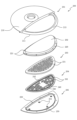
- FIG. 5 is an exploded perspective view of the electronic percussion instrument 200 in the second embodiment. Note that FIG. 5 shows a state in which a cover 206 (see FIG. 6 or 8), which will be described later, is removed from the main body frame 201.
- the electronic percussion instrument 200 of the second embodiment is a percussion instrument that imitates an acoustic cymbal.
- the skeleton of the electronic percussion instrument 200 is formed by a main body frame 201.
- the main body frame 201 includes an upper surface portion 210 that forms the upper surface of the electronic percussion instrument 200 .
- a circular arc portion 211 is connected to a linear portion of the flat semicircular upper surface portion 210 .
- the upper surface portion 210 and the arcuate portion 211 are integrally formed using a resin material, and the outer edge of the main body frame 201 is formed into a circular shape as a whole by these portions 210 and 211.
- a semicircular opening surrounded by the upper surface part 210 and the arcuate part 211 is a space for accommodating the head 202.
- a head frame 220 is connected to the outer edge of the head 202, and these head 202 and head frame 220 are similar to the head 1 and head frame 10 of the first embodiment, except that the shape is semicircular. It is the composition. Note that, like the head 202 and head frame 220, each member of an elastic body 203, a support frame 204, and a base frame 205, which will be described later, is also formed in a semicircular shape (having a straight portion and an arcuate portion). ). Therefore, in the following description, the edges along the straight line portions and arcuate portions of each semicircular member will be described as “straight line portion of head frame 220”, “circle portion of base frame 205”, etc.
- a plurality of insertion holes 221 are formed in each of the straight portion and the arcuate portion of the head frame 220.
- This insertion hole 221 is a hole for fastening the head frame 220 and the base frame 205 together with the upper surface part 210 and the circular arc part 211 of the main body frame 201 with bolts B2 (see FIG. 6).
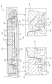
- FIG. 6 is a partially enlarged sectional view of the electronic percussion instrument 200. Note that FIG. 6 shows a cross section cut along a plane including the insertion hole 250 (insertion hole 250 formed in the straight portion and arcuate portion of the base frame 205) labeled with the reference numeral 250 in FIG. Moreover, in FIG. 6, only a cut surface (end surface) of the electronic percussion instrument 200 is mainly illustrated, excluding some internal structures (such as the bolt B3).
- the base frame 205 is formed of resin into a flat semicircular shape, and the straight portions and arcuate portions of the base frame 205 have upper and lower sides with the insertion holes 221 of the head frame 220. A plurality of facing insertion holes 250 are formed.
- a plurality of female screw holes 212 are formed on the lower surface of each of the upper surface portion 210 and the arcuate portion 211 of the main body frame 201.
- the head frame 220 and the base frame 205 are fixed to the lower surface of the main body frame 201 by screwing the bolts B2 inserted into the insertion holes 221 and 250 of the head frame 220 and the base frame 205 into the female threaded holes 212, respectively.
- a support frame 204 and an elastic body 203 supported by the support frame 204 are housed in the space between the head 202 and the base frame 205.
- the support frame 204 is supported by the base frame 205 via bolts B3 (see FIG. 6), and this support structure will be described later with reference to FIG. 7.
- the support frame 204 is formed in a flat semicircular shape using resin.
- a groove-shaped positioning recess 240 for positioning the elastic body 203 is formed on the upper surface of the linear portion and the arcuate portion of the support frame 204.
- a positioning convex portion 230 (see FIG. 6) having a shape corresponding to the positioning recess 240 is formed on the lower surface of the linear portion and the circular arc portion of the elastic body 203.
- the elastic body 203 may be adhered to the support frame 204 with the positioning convex portion 230 of the elastic body 203 fitted into the positioning recess 240, or the elastic body 203 may simply be placed on the support frame 204 (without adhesive). (No) configuration is also acceptable.
- the elastic body 203 is formed using an elastic body (rubber, elastomer, foamed material thereof, etc.) having a predetermined flexibility, so that when the player hits the head 202 with a stick or the like (hereinafter referred to as "the head 202 When the head 202 is hit (hereinafter referred to as "the time of impact"), the vibration of the head 202 caused by the impact is absorbed by the elastic body 203. Thereby, it is possible to reduce the hitting sound when the head 202 is hit.
- an elastic body rubber, elastomer, foamed material thereof, etc.
- the vibrations generated when the head 202 is hit are detected by the head sensor S1 (see FIG. 6).
- the head sensor S1 is a disk-shaped piezoelectric element, and is adhered to the lower surface of the support frame 204 with a double-sided tape having cushioning properties. Vibrations generated when the head 202 is hit are transmitted to the head sensor S1 via the elastic body 203 and the support frame 204.
- the elastic body 203 Since the elastic body 203 is formed with a plurality of through holes 231 connecting its upper and lower surfaces, the vibration of the elastic body 203 is reduced when the head 202 is hit, compared to a case where such through holes 231 are not formed. It can effectively reduce the noise caused by On the other hand, in a region where the through hole 231 is not formed, vibrations generated when the head 202 is hit are transmitted to the support frame 204 via the elastic body 203 itself. Therefore, the impact to the head 202 can be detected with high accuracy while reducing the impact sound when the head 202 is hit.
- the through hole 231 having a circular cross section extends vertically in a straight line, and the cross sectional area (inner diameter) of the through hole 231 is constant from the upper end to the lower end, but this is not necessarily the case. isn't it.
- the through hole 231 may have a linear shape that is inclined with respect to the thickness direction (vertical direction) of the elastic body 203, or the through hole 231 may have a shape that is a combination of straight lines and curves from the upper end to the lower end (for example, It may be formed in a spiral shape, meandering shape, etc.).
- the cross-sectional shape of the through-hole 231 may be a honeycomb shape (hexagonal cross-section) or other polygonal shape, and the cross-sectional shape of the through-hole 231 may be formed in a part or all of the region from the upper end to the lower end of the through-hole 231.
- a configuration in which the area (inner diameter) changes may also be used.
- the hardness measured with a durometer type A hardness tester is 10 or more in accordance with JIS K6253-3:2012. It is preferable to use an elastic material exhibiting a resistance of 50 or less.
- the elastic body 203 is formed from a foam material (sponge) such as rubber or synthetic resin, the hardness measured with a durometer type E hardness tester must be 20 or more and 75 or less in accordance with JIS K6253-3:2012. It is preferable to use the foamed material shown below.
- the head 202 is breathable, and the support frame 204 is formed with a plurality of through holes 241 that connect its upper and lower surfaces. Furthermore, a plurality of through holes (see FIG. 7) are also formed in the base frame 205 in an area facing the support frame 204. That is, the electronic percussion instrument 200 has an air flow path that passes through the head 202, the elastic body 203, the support frame 204, and the base frame 205. Thereby, when the head 202 is hit, it is possible to reduce the sound generated by the vibration of the head 202 itself and the sound generated by the resonance of other members such as the support frame 204 and the base frame 205.
- the elastic body 203 is in contact with the head 202. This allows the elastic body 203 to easily absorb vibrations when the head 202 is hit, so that it is possible to effectively reduce the hitting sound when the head 202 is hit.
- an insertion hole 251 is formed in the upper surface of the base frame 205 to rotatably insert the head of the bolt B3.
- the insertion holes 251 are formed at three locations along the straight portion of the base frame 205 (see FIG. 5) and at one location at the center of the arcuate portion.
- a female threaded hole 242 is formed in the support frame 204 at a position facing the insertion hole 251 of the base frame 205 from above and below. Therefore, with the bolt B3 screwed into the female threaded hole 242 from below inserted (placed) in the insertion hole 251 of the base frame 205, by turning the bolt B3 in the direction to remove (loosen) from the female threaded hole 242, Support frame 204 can be displaced upwardly relative to base frame 205. On the other hand, by turning the bolt B3 in the direction in which it is screwed into the female threaded hole 242, the support frame 204 can be displaced downward. That is, by adjusting the screwing amount of the bolt B3, the support frame 204 can be vertically displaced relative to the base frame 205.
- the impact on the head 202 which imitates the bow of a cymbal, is detected by the head sensor S1 as described above.
- a blow to the arcuate portion 211 of the main body frame 201 which imitates the edge portion of a bow, is detected by an edge sensor (not shown) attached to the sensor mounting surface 213 of the arcuate portion 211.
- the sensor mounting surface 213 is inclined downward toward the outer circumferential side of the arc portion 211, and an edge sensor is bonded to this sensor mounting surface 213.
- the edge sensor is a sheet-like pressure-sensitive sensor (for example, a membrane switch).
- the upper and lower surfaces of the arc portion 211 including the sensor mounting surface 213 are covered by a rubber cover 206 (see FIG. 7), but there is a space between the sensor mounting surface 213 (edge sensor) and the cover 206. It is formed. Therefore, when the player hits the cover 206 with a stick or the like, the edge sensor is pushed in by the elastic deformation of the cover 206. As a result, a hit to the cover 206 (arc part 211) is detected by the edge sensor.
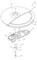
- a circular insertion hole 214 is formed in the upper surface portion 210 of the main body frame 201, and the inserted portion 270 of the case 207 is inserted into this insertion hole 214.
- the inserted portion 270 is formed in a cylindrical shape, and a projecting portion 271 projects from the lower end of the inserted portion 270 in the shape of a flange.
- a bottom wall 272 (see FIG. 8) of the case 207 is connected to the outer peripheral surface of the projecting portion 271, and an outer wall 273 projects upward from the outer edge of the bottom wall 272.
- case 207 is attached to the main body frame 201 by screwing with bolts (not shown) while the inserted part 270 is inserted into the insertion hole 214 of the main body frame 201 (upper surface part 210).
- a space is formed surrounded by the lower surface of the upper surface 210 of the main body frame 201, the bottom wall 272, and the outer wall 273, and electronic components such as circuit boards are housed in this space.
- the inner circumferential surface 274c of the protrusion 274b is a plane that slopes downward from the lower end of the rod insertion hole 274a toward the outer circumferential side (direction away from the rod insertion hole 274a). ) is set to be the same as (or smaller than) the angle of inclination of the inclined surface 512 of the support 501 with respect to the axis of the rod 500.
- the electronic percussion instrument 200 is allowed to swing due to the elastic deformation of the protrusion 274b (third elastic body). Specifically, a groove 274f surrounding the outer peripheral surface 274e of the protrusion 274b is formed on the lower surface of the supported portion 274. Therefore, when the head 202 located on the opposite side (the right side in FIG. 7) of the rod 500 (rod insertion hole 274a) across the protrusion 274b is hit, the deformation of the protrusion 274b due to the impact is compensated for by the groove 274f. I can accept it. This deformation of the protrusion 274b allows the electronic percussion instrument 200 to swing relative to the rod 500 (support 501).
- an electronic percussion instrument 300 includes a first frame 301a including a circular arc portion 211 (see FIG. 10) similar to the second embodiment described above; and a second frame 301b that is connected so as to be overlapped with the second frame 301b.
- the fixed part 310a extends in the horizontal direction (up and down direction in FIG. 11) so as to connect both ends of the circular arc part 211, and the fixed part 310a and the circular arc part 211 are integrally formed using a resin material. .
- the longitudinal direction is the direction in which the fixing part 310a extends from one end of the arcuate part 211 to the other end (vertical direction in FIG. 11)
- a circular insertion hole 311a is formed in the longitudinal center of the fixing part 310a.
- the inserted portion 270 of the support rubber 308 (see FIG. 10) is inserted into the insertion hole 311a.
- a female threaded hole 212 (see enlarged portion in FIG. 6) similar to that of the second embodiment described above is formed on the lower surface of the fixing portion 310a and the arcuate portion 211.
- the base frame 205 (see FIG. 6) is screwed into this female threaded hole 212, the semicircular opening surrounded by the fixed part 310a and the circular arc part 211 has the head 202 (see FIG. 6) which becomes the hitting surface. 11) is accommodated. That is, the first frame 301a supports the head 202 from the peripheral side, and the first frame 301a is adjacent to the head 202 so as to surround it. Therefore, the vibration when the head 202 is hit is detected by the head sensor S1 (see FIG. 6), as in the second embodiment, and the head sensor S1 is connected to the first It is supported by frame 301a.
- the first frame 301a consisting of the fixed part 310a and the arcuate part 211 is a frame that forms the skeleton of the hitting area (hitting surface) hit by the player.
- the second frame 301b which is connected to the first frame 301a so as to overlap it, constitutes the upper surface of the electronic percussion instrument 300 together with the head 202 and the cover 206 (beating surface). is not installed.
- the second frame 301b is a decorative frame for forming a disc-shaped electronic percussion instrument 300 imitating a cymbal together with the first frame 301a (to improve the appearance of the electronic percussion instrument 300), and the upper surface of the second frame 301b is a non-striking surface that is not intended to receive a blow.
- the second frame 301b is formed in a semicircular shape having a bell part 310b and a bow part 311b shaped to imitate an acoustic cymbal, and these bell part 310b and bow part 311b are integrally formed using a resin material.
- a circular insertion hole 312b for inserting the rod 500 is formed in the center of the bell portion 310b, and the bell portion 310b is formed in a bowl shape that slopes downward toward the outer circumference from the insertion hole 312b. .
- the details of the support structure (see FIG. 12) for the second frame 301b by the elastic bodies 309a to 309c will be described later, but by elastically supporting the second frame 301b to the first frame 301a via the elastic bodies 309a to 309c, the head
- the elastic bodies 309a to 309c can attenuate vibrations transmitted from the first frame 301a to the second frame 301b when hitting the cover 202 or the cover 206 (see FIG. 11). Therefore, noise caused by vibration of the second frame 301b can be suppressed, and a good performance feeling can be provided to the player.
- the through hole 390 is a hole for fixing the base end portion (one end side) of the elastic bodies 309a to 309c to the first frame 301a
- the through hole 391 is a hole for fixing the base end portion (one end side) of the elastic bodies 309a to 309c. This is a hole for fixing the second frame 301b to.
- the fixing structure of the second frame 301b using the elastic body 309a will be mainly explained, but the fixing structure of the second frame 301b using the elastic bodies 309b and 309c also has substantially the same configuration.
- a female screw hole 314a is formed in each of the fixing protrusions 313a (see the enlarged part in FIG. 12), and the through holes 390 of the elastic bodies 309a to 309c are fitted into the fixing protrusions 313a.
- the elastic body 309a is fixed to the first frame 301a by screwing the bolt B4 into the female threaded hole 314a.
- the washer W1 sandwiched between the upper surface of the fixing protrusion 313a and the head of the bolt B4 causes upward displacement of the elastic body 309a (falling off of the elastic body 309a from the fixing protrusion 313a of the first frame 301a). ) are regulated.
- the thickness of the elastic body 309a around the fixing protrusion 313a is formed to be the same as the height of the fixing protrusion 313a.
- a female threaded hole 314b is formed in the fixing protrusion 313b, and with the fixing protrusion 313b inserted into the through hole 391 of the elastic body 309a, by screwing the bolt B5 into the female threaded hole 314b, the second frame 301b is attached to the elastic body 309a. is fixed. In this fixed state, the upward displacement of the second frame 301b (the movement of the second frame 301b from the through hole 391 of the elastic body 309a) is caused by the washer W2 sandwiched between the lower surface of the fixing protrusion 313b and the head of the bolt B5. (falling off) is regulated.
- a washer W3 is also sandwiched between the support protrusion 392 of the elastic body 309a and the lower surface of the second frame 301b.
- the thickness is the same as the interval between washers W2 and W3.
- the second frame 301b is elastically supported by the three elastic bodies 309a to 309c (see FIG. 11).
- the elastic body 309a fixed to the protrusion 312a protrudes further toward the outer periphery than the protruding tip of the protrusion 312a, and is fixed to the first frame 301a in a cantilevered manner.
- a pair of elastic bodies 309b, 309c are fixed to both ends of the fixed part 310a in the longitudinal direction (vertical direction in FIG. 11).
- a through hole 315a passing through the fixing part 310a is formed. That is, the elastic bodies 309b and 309c are similarly fixed to the first frame 301a in a cantilevered manner.
- the second frame 301b By allowing the second frame 301b to swing relative to the first frame 301a, it becomes easier for only the first frame 301a to swing when the head 202 or cover 206 is hit (the swing of the second frame 301b is (can be made relatively small). Thereby, noise caused by the rocking (vibration) of the second frame 301b can be effectively reduced.
- the elastic bodies 309a to 309c are fixed to the respective frames 301a and 301b with bolts B4 and B5, so in order to stably (firmly) hold the elastic bodies 309a to 309c at these fixed parts, it is necessary to use a relatively hard material. It is preferable to form the elastic bodies 309a to 309c using high-quality rubber. On the other hand, if the hardness of the rubber is made too high, the elastic bodies 309a to 309c become difficult to bend, making it difficult for the second frame 301b to swing relative to the first frame 301a.
- the elastic bodies 309a to 309c of this embodiment are formed into a plate shape whose thickness in the vertical direction is smaller than the thickness in the width direction.
- the elastic bodies 309a to 309c easily bend up and down. Therefore, the elastic bodies 309a to 309c can be stably held at the portions fixed by the bolts B4 and B5, and the second frame 301b can be easily swung relative to the first frame 301a.
- the second frame 301b swings relative to the first frame 301a, the second frame 301b is moved by other members (head 202, cover 206, support rubber 308, etc.). By preventing such contact, it is possible to suppress the generation of collision sounds between the second frame 301b and other members and the head sensor S1's erroneous detection of vibrations caused by the collision, and also prevent the second frame 301b from erroneously detecting vibrations caused by the collision. (other members) can be prevented from being damaged.
- the elastic bodies 309a to 309c protrude in the radial direction about the center of the insertion hole 311a of the first frame 301a, that is, the swing axis O of the electronic percussion instrument 300 (see FIG. 11). This is to allow the entire second frame 301b to move up and down uniformly with respect to the swinging of the first frame 301a when the head 202 is hit.
- the elastic bodies 309a to 309c can be fixed to the lower surface side of the first frame 301a, but in this embodiment, they are fixed to the upper surface side of the first frame 301a. This is to improve the appearance by suppressing exposure of some of the elastic bodies 309a to 309c and their fixed parts (bolts B4 and washers W1).
- the direction around the axis of the bolt B4 is the circumferential direction
- three buffer protrusions 393 are formed at equal intervals in the circumferential direction of the bolt B4 (see the enlarged part in FIG. 11).
- the contact area between the buffer protrusion 393 and the second frame 301b can be reduced, compared to, for example, the case where the buffer protrusion 393 is formed in a continuous annular shape in the circumferential direction of the bolt B4. Can be reduced. Therefore, noise generated when the buffer protrusion 393 and the second frame 301b collide can be reduced.
- each of the plurality of buffer protrusions 393 is formed into a plate shape surrounding the bolt B4, and a groove 394 (see enlarged part in FIG. 12) is formed on the outer peripheral surface of each buffer protrusion 393 facing away from the bolt B4. ) is formed.
- This groove 394 is for deforming the buffer protrusion 393 to the side opposite to the bolt B4 and the washer W1 when the buffer protrusion 393 comes into contact with the second frame 301b.
- a groove 394 is formed on the outer peripheral surface of the buffer protrusion 393, and the groove 394 extends across both ends of the buffer protrusion 393 in the circumferential direction of the bolt B4. This can prevent the buffer protrusion 393 from deforming toward the bolt B4 (washer W1) when it comes into contact with the second frame 301b, thereby suppressing the buffer protrusion 393 from coming into contact with the bolt B4 or the washer W1. Therefore, even if the second frame 301b and the buffer protrusion 393 repeatedly come into contact with each other, the buffer protrusion 393 is less likely to be damaged.
- a wall-shaped regulating wall 317a is integrally formed on the upper surface of the first frame 301a along a side surface 397 facing in the width direction of the elastic body 309a, and the elastic body 309a has a pair of regulating walls 317a on both sides in the width direction. sandwiched between.
- the contact between the regulating wall 317a and the side surface 397 of the elastic body 309a can also regulate the rotation of the elastic body 309a around the fixed protrusion 313a.
- Such regulating walls 316a, 317a are similarly formed around the elastic bodies 309b, 309c (see FIG. 10), and these regulating walls 316a, 317a can regulate the rotation of the elastic bodies 309a to 309c.
- This makes it possible to suppress rotation of the second frame 301b relative to the first frame 301a, thereby making the gap between the second frame 301b and other members (for example, the head 202) relatively small.
- the second frame 301b can be prevented from coming into contact with other members due to swinging when the head 202 is hit. Therefore, it is possible to suppress the generation of noise due to contact between the second frame 301b and other members while suppressing the electronic percussion instrument 300 from increasing in size or deteriorating its appearance.
- it is possible to suppress the head sensor S1 from erroneously detecting vibrations caused by contact between the second frame 301b and other members.
- the wall-like regulating walls 316a, 317a rising from the upper surface of the first frame 301a and the outer circumferential surfaces of the elastic bodies 309a to 309c (base end surface 395, side surface of the regulating protrusion 396, and side surface 397)
- the configuration is such that rotation of the elastic bodies 309a to 309c is restricted by contact. With such a configuration, rotation of the elastic bodies 309a to 309c can be restricted at a position away from the fixed protrusion 313a.
- the head 1, 202 may be formed from other breathable materials, such as cloth, nonwoven fabric, or a film with through holes, or the head 1, 202 may be made of non-breathable material (for example, synthetic resin).
- the head 1, 202 may be formed from a film made of
- the elastic body 3,203 is made of an elastic material showing a hardness of 10 or more and 50 or less on a durometer type A hardness tester, or a foam material showing a hardness of 20 or more and 75 or less on a durometer type E hardness tester.
- the elastic body 3, 203 may be formed using a material that is harder or softer than the above-mentioned hardness.
- the elastic body 3, 203 is not necessarily limited to this.
- a plurality of elastic bodies 3, 203 may be stacked one above the other, or one or more layers of elastic bodies 3, 203 may be stacked on top of other elastic bodies 3, 203. It may be formed with a hardness different from that of 203.
- the through holes 32, 231 having a honeycomb shape (hexagonal cross section) or a circular cross section are scattered in the elastic bodies 3, 203, but the present invention is not necessarily limited to this.
- the through holes 32, 231 may be elongated holes with a combination of straight lines and curved lines, or such elongated through holes 32, 231 may be honeycomb-shaped (or other polygons) or circular in cross section.
- a configuration in which the through holes 32 and 231 are combined (formed so as to be connected) may also be used.
- the upper and lower surfaces of the elastic bodies 3, 203 may be flat, and the upper and lower surfaces of the elastic bodies 3, 203 may be flat. Irregularities or grooves may be formed on at least one (or both) of the lower surfaces.
- the case where the head sensor S1 is attached to the sensor support member 4 is explained, and in the second embodiment, the case is explained where the head sensor S1 is attached to the lower surface of the support frame 204, but this is not necessarily the case. It is not limited.
- the head sensor S1 may be directly attached to the upper surface or lower surface of the support section 20.
- the sensor support member 4 to which the head sensor S1 is attached may be fixed to the lower surface of the support frame 204, or the head sensor S1 may be directly attached to the upper surface of the support frame 204.
- the elastic body 3, 203 contacts the head 1, 202 before impact, but the invention is not necessarily limited to this. If the elastic body 3,203 is configured to come into contact with the head 1,202 at least when the head 1,202 is struck, then part or all of the elastic body 3,203 will come into contact with the head 1,202 before striking. You don't have to.
- the honeycomb-shaped (hexagonal cross-section) through-holes 26, 241 extending vertically are formed in the body portion 2 (support portion 20) and the support frame 204, and the cross-sectional area of the through-holes 26, 241 ( Although the inner diameter is constant from the upper end to the lower end, it is not necessarily limited to this.
- the through holes 26 and 241 may be inclined with respect to the thickness direction (vertical direction) of the support part 20 and the support frame 204, or the cross-sectional shape of the through holes 26 and 241 may be other polygonal shapes or circular shapes. It's okay.
- the cross-sectional area (inner diameter) of the through-holes 26, 241 may change in a part or all of the region from the upper end to the lower end of the through-holes 26, 241. Further, the through holes 26 and 241 may be omitted.
- the present invention is not necessarily limited to this.
- a configuration may be adopted in which the outer frame member 5 and the elastic body 6 are omitted.
- a rim sensor for example, a sheet-like membrane switch
- an electronic percussion instrument 100 imitating an acoustic drum can be configured.
- the supporting position of the elastic body 6 by the outer frame member 5 (bottom part 51) is located on the inner circumferential side of the supporting position of the trunk part 2 (bottom wall 22) by the elastic body 6 will be described.
- the position where the elastic body 6 is supported by the outer frame member 5 is located on the outer peripheral side of the position where the body 2 is supported by the elastic body 6 (the outer frame member 5 is fixed to the outer edge side of the elastic body 6, and the elastic body 6 is supported by the elastic body 6). 6), the supporting positions of those two points may be shifted in the radial direction.
- the elastic body 6 is formed in an annular shape (continuously in the circumferential direction), but the elastic body 6 is not necessarily limited to this.
- the body 2 may be supported by a plurality of elastic bodies 6 arranged in the circumferential direction (intermittent).
- the rim sensor S2 piezoelectric element
- the rim sensor S2 may be omitted, and a sheet-like pressure sensor (for example, a membrane switch, etc.) provided between the recess 52 of the outer frame member 5 and the rim 53 may detect the impact on the rim 53.
- the rim 53 (base portion 53a) may be joined to the outer peripheral portion 50 (recessed portion 52) of the outer frame member 5 by integral molding using a mold (vulcanization adhesion) or by other known means such as welding. good. Also in this configuration, it is possible to suppress the flapping of the rim 53 during impact.
- the bolt B3 screwed into the support frame 204 (the head is placed in the insertion hole 251 of the base frame 205) is illustrated as an example of the displacement means for pushing the support frame 204 upward. It is not necessarily limited to this.
- the support frame 204 may be pushed up by the shaft of a bolt screwed into the base frame 205 from below. That is, the configuration is not limited to the above-mentioned configuration as long as the support frame 204 can be vertically displaced relative to the base frame 205.
- an elastic body third elastic body that suppresses the electronic percussion instrument 200 from tilting with respect to the rod 500 before striking, but allows the electronic percussion instrument 200 to swing during striking.
- the protrusion 274b integrally formed on the support portion 274 is illustrated, the present invention is not necessarily limited to this.
- a configuration may be adopted in which an elastic body (corresponding to the protrusion 274b) formed separately from the supported part 274 is interposed between the supported part 274 and the support tool 501 (the inclined surface 512).
- a pair of planar inclined surfaces 512 are inclined downward toward the outer peripheral surface 511 of the support 501.
- the configuration is not necessarily limited to this.
- part or all of the pair of inclined surfaces 512 may be formed into a curved surface, or the support surface may be formed into a conical or hemispherical shape.
- the rubber elastic bodies 309a to 309c are fixed to the first frame 301a in a cantilevered manner, but this is not necessarily the case.
- the entire elastic bodies 309a to 309c may be supported by the first frame 301a, or other known elastic bodies such as a coil spring or a plate spring may be interposed between the frames 301a and 301b. That is, other known support structures can be applied as long as they are structures that can elastically connect two frames (plate-shaped members) to each other.
- Other known support structures include a structure in which the first plate 41 is elastically supported with respect to the second plate 44 using an elastic member 44b and a connecting screw 45, as disclosed in Japanese Unexamined Patent Publication No. 2013-142872. , such a support structure may be applied to each frame 301a, 301b.
- the elastic bodies 309a to 309c are fixed to the respective frames 301a and 301b using bolts B4 and B5, but this is not necessarily the case.
- the bolts B4 and B5 may be omitted and the elastic bodies 309a to 309c may be joined (adhered or welded) to each frame 301a and 301b.
- the regulating walls 316a, 317a (rotation regulating means) of the first frame 301a may be omitted. That is, the method of fixing the elastic bodies 309a to 309c to each frame 301a, 301b can be set as appropriate.
- the present invention is not necessarily limited to this.
- a region on the opposite side of the head 202 (hitting surface) with the rod 500 in between is a second region when hitting the head 202 or the cover 206. Since the swing of the frame 301b tends to be large, the rigidity (hardness and thickness in the vertical direction) of the elastic body 309a disposed in this region may be made larger than the other elastic bodies 309b and 309c.
- the second frame 301b (inner circumferential surface of the insertion hole 312b) is not in contact with the rod 500, but this is not necessarily the case.
- the second frame 301b may be supported by the rod 500 via the support rubber 308.
- An example of such a configuration is a support structure for a bow frame 4 using support rubber 3 disclosed in International Publication No. 2022-044171.
- the elastic bodies 309a to 309c protrude in the radial direction centered on the rod 500, that is, in the radial direction centered on the rocking axis O of the electronic percussion instrument 300 and the elastic bodies 309a to 309c
- the longitudinal direction of the elastic bodies 309a to 309c may not coincide with the radial direction centered on the swing axis O (for example, be inclined).
- the elastic bodies 309a to 309c are formed in a semi-elliptical shape when viewed from above, but the present invention is not necessarily limited to this.
- the elastic bodies 309a to 309c may be rectangular or circular in plan view. That is, the shapes of the elastic bodies 309a to 309c can be set as appropriate as long as they can elastically support the second frame 301b with respect to the first frame 301a.
- a plurality of buffer protrusions 393 surrounding the bolt B4 are illustrated as an example of a means (contact regulating means) for regulating the contact between the bolt B4 and the second frame 301b, but the invention is not necessarily limited to this.
- the buffer protrusion 393 may be formed in a continuous ring shape in the circumferential direction of the bolt B4.
- the elastic bodies 309a to 309c around the bolt are made thicker overall (the bolt B4 is embedded in the recess), so that the bolt B4 and the second frame 301b are contact may be restricted.
- the elastic bodies 309a to 309a are caused by contact between the regulating walls 316a and 317a of the first frame 301a and the outer peripheral surfaces of the elastic bodies 309a to 309c (base end surface 395, side surface of the regulating protrusion 396, and side surface 397).
- base end surface 395, side surface of the regulating protrusion 396, and side surface 397 base end surface 395, side surface of the regulating protrusion 396, and side surface 397.
- other configurations for restricting the rotation of the elastic bodies 309a to 309c include a configuration in which unevenness that can be fitted to each other is formed in the through hole 390 and the fixing protrusion 313a, or a configuration in which the elastic bodies 309a to 309c are joined to the first frame 301a. The configuration is illustrated.
- the head 202 (elastic body 203), the support frame 204, and the base frame 205 are omitted, and the first frame is formed in a plate shape that closes the space surrounded by the fixed part 310a and the circular arc part 211.
- the head sensor S1 may be attached to one frame. That is, in order to form a hitting surface corresponding to the head 202 with the upper surface of the plate-shaped first frame (or a cushioning cover such as rubber that covers the upper surface), vibrations when hitting the hitting surface are detected.
- the sensor may be directly supported by the first frame.
- the head 202 and the first frame 301a may be formed integrally.
Landscapes
- Physics & Mathematics (AREA)
- Engineering & Computer Science (AREA)
- Acoustics & Sound (AREA)
- Multimedia (AREA)
- Electrophonic Musical Instruments (AREA)
Priority Applications (4)
| Application Number | Priority Date | Filing Date | Title |
|---|---|---|---|
| CN202380011198.0A CN117642812A (zh) | 2022-06-23 | 2023-06-14 | 电子打击乐器及打击音的减音方法 |
| US18/287,299 US20250078787A1 (en) | 2022-06-23 | 2023-06-14 | Electronic percussion instrument and percussion sound reduction method |
| JP2023548796A JP7551941B2 (ja) | 2022-06-23 | 2023-06-14 | 電子打楽器および打音の減音方法 |
| EP23827083.9A EP4546330A1 (en) | 2022-06-23 | 2023-06-14 | Electronic percussion instrument and method for reducing striking sound |
Applications Claiming Priority (2)
| Application Number | Priority Date | Filing Date | Title |
|---|---|---|---|
| JP2022100870 | 2022-06-23 | ||
| JP2022-100870 | 2022-06-23 |
Publications (1)
| Publication Number | Publication Date |
|---|---|
| WO2023248897A1 true WO2023248897A1 (ja) | 2023-12-28 |
Family
ID=89379833
Family Applications (2)
| Application Number | Title | Priority Date | Filing Date |
|---|---|---|---|
| PCT/JP2023/022108 Ceased WO2023248897A1 (ja) | 2022-06-23 | 2023-06-14 | 電子打楽器および打音の減音方法 |
| PCT/JP2023/022109 Ceased WO2023248898A1 (ja) | 2022-06-23 | 2023-06-14 | 電子打楽器および非打撃面の形成方法 |
Family Applications After (1)
| Application Number | Title | Priority Date | Filing Date |
|---|---|---|---|
| PCT/JP2023/022109 Ceased WO2023248898A1 (ja) | 2022-06-23 | 2023-06-14 | 電子打楽器および非打撃面の形成方法 |
Country Status (5)
| Country | Link |
|---|---|
| US (2) | US20250078787A1 (https=) |
| EP (2) | EP4546330A1 (https=) |
| JP (2) | JP7551941B2 (https=) |
| CN (2) | CN117642811A (https=) |
| WO (2) | WO2023248897A1 (https=) |
Citations (8)
| Publication number | Priority date | Publication date | Assignee | Title |
|---|---|---|---|---|
| JPH0635450A (ja) | 1992-07-14 | 1994-02-10 | Roland Corp | 電子打楽器 |
| JP2001142459A (ja) | 1999-11-15 | 2001-05-25 | Yamaha Corp | ドラム、減音装置および電子打楽器用ヘッド |
| JP2004287356A (ja) * | 2003-01-31 | 2004-10-14 | Yamaha Corp | ドラムヘッドとドラムおよび電子ドラム並びにドラムシステムと電子ドラムシステム |
| JP2010224330A (ja) * | 2009-03-25 | 2010-10-07 | Korg Inc | 電子ドラム |
| JP2013142872A (ja) | 2012-01-12 | 2013-07-22 | Roland Corp | 電子打楽器 |
| JP2017026726A (ja) | 2015-07-20 | 2017-02-02 | ローランド株式会社 | 錘部材および打撃用パッド |
| JP2019148623A (ja) | 2018-02-26 | 2019-09-05 | ローランド株式会社 | 電子打楽器 |
| WO2022044171A1 (ja) | 2020-08-26 | 2022-03-03 | ローランド株式会社 | 電子打楽器および打撃の検出方法 |
Family Cites Families (2)
| Publication number | Priority date | Publication date | Assignee | Title |
|---|---|---|---|---|
| JPS60166000U (ja) * | 1984-04-13 | 1985-11-02 | ヤマハ株式会社 | 電子シンバル |
| JP6652157B2 (ja) * | 2013-03-12 | 2020-02-19 | ヤマハ株式会社 | 電子打楽器 |
-
2023
- 2023-06-14 JP JP2023548796A patent/JP7551941B2/ja active Active
- 2023-06-14 EP EP23827083.9A patent/EP4546330A1/en active Pending
- 2023-06-14 EP EP23827084.7A patent/EP4546331A1/en active Pending
- 2023-06-14 US US18/287,299 patent/US20250078787A1/en active Pending
- 2023-06-14 US US18/287,302 patent/US20250078788A1/en active Pending
- 2023-06-14 CN CN202380011194.2A patent/CN117642811A/zh active Pending
- 2023-06-14 JP JP2023548797A patent/JP7579984B2/ja active Active
- 2023-06-14 WO PCT/JP2023/022108 patent/WO2023248897A1/ja not_active Ceased
- 2023-06-14 WO PCT/JP2023/022109 patent/WO2023248898A1/ja not_active Ceased
- 2023-06-14 CN CN202380011198.0A patent/CN117642812A/zh active Pending
Patent Citations (8)
| Publication number | Priority date | Publication date | Assignee | Title |
|---|---|---|---|---|
| JPH0635450A (ja) | 1992-07-14 | 1994-02-10 | Roland Corp | 電子打楽器 |
| JP2001142459A (ja) | 1999-11-15 | 2001-05-25 | Yamaha Corp | ドラム、減音装置および電子打楽器用ヘッド |
| JP2004287356A (ja) * | 2003-01-31 | 2004-10-14 | Yamaha Corp | ドラムヘッドとドラムおよび電子ドラム並びにドラムシステムと電子ドラムシステム |
| JP2010224330A (ja) * | 2009-03-25 | 2010-10-07 | Korg Inc | 電子ドラム |
| JP2013142872A (ja) | 2012-01-12 | 2013-07-22 | Roland Corp | 電子打楽器 |
| JP2017026726A (ja) | 2015-07-20 | 2017-02-02 | ローランド株式会社 | 錘部材および打撃用パッド |
| JP2019148623A (ja) | 2018-02-26 | 2019-09-05 | ローランド株式会社 | 電子打楽器 |
| WO2022044171A1 (ja) | 2020-08-26 | 2022-03-03 | ローランド株式会社 | 電子打楽器および打撃の検出方法 |
Also Published As
| Publication number | Publication date |
|---|---|
| WO2023248898A1 (ja) | 2023-12-28 |
| EP4546330A1 (en) | 2025-04-30 |
| EP4546331A1 (en) | 2025-04-30 |
| JP7551941B2 (ja) | 2024-09-17 |
| JP7579984B2 (ja) | 2024-11-08 |
| CN117642811A (zh) | 2024-03-01 |
| US20250078788A1 (en) | 2025-03-06 |
| CN117642812A (zh) | 2024-03-01 |
| US20250078787A1 (en) | 2025-03-06 |
| JPWO2023248898A1 (https=) | 2023-12-28 |
| JPWO2023248897A1 (https=) | 2023-12-28 |
Similar Documents
| Publication | Publication Date | Title |
|---|---|---|
| JP2004198657A (ja) | 電子打楽器および振動検出装置 | |
| JPH043356Y2 (https=) | ||
| US7612273B2 (en) | Electronic percussion instrument | |
| EP2477184B1 (en) | A drumhead having a drum damping fixture, and a musical drum incorporating such a drumhead | |
| JP2004287356A (ja) | ドラムヘッドとドラムおよび電子ドラム並びにドラムシステムと電子ドラムシステム | |
| JP4845970B2 (ja) | 反発が向上されたドラムヘッドアセンブリ | |
| US5922980A (en) | Sound muffling device for cymbal practice | |
| US10467996B2 (en) | Cymbal damping tool and method of producing the same | |
| JP4132170B2 (ja) | 打面装置および電子打楽器 | |
| WO2023248897A1 (ja) | 電子打楽器および打音の減音方法 | |
| JP4140531B2 (ja) | 電子ドラム用パッド | |
| JP2005274727A (ja) | 打楽器用パッド | |
| JP5329109B2 (ja) | 電子打楽器 | |
| JP2022154527A (ja) | 電子ハイハット及び電子ハイハットの動作方法 | |
| JP7279946B2 (ja) | スネアドラム用練習パッド | |
| US20030200856A1 (en) | Drum pillow and method for using same | |
| US20250022448A1 (en) | Electronic percussion instrument and percussion detection method | |
| US20250022443A1 (en) | Electronic percussion instrument and cover installation method | |
| WO2009110838A1 (en) | Drum head for electronic percussion instrument | |
| CN118382890A (zh) | 电子打击乐器及击打的检测方法 | |
| CN223390262U (zh) | 镲片垫圈 | |
| EP3843082B1 (en) | Drum head and attachment method of cushion | |
| JP5626297B2 (ja) | 電子打楽器 | |
| US11222617B1 (en) | Snare drum practice pad | |
| JP2025127703A (ja) | 打楽器および打面の形成方法 |
Legal Events
| Date | Code | Title | Description |
|---|---|---|---|
| ENP | Entry into the national phase |
Ref document number: 2023548796 Country of ref document: JP Kind code of ref document: A |
|
| WWE | Wipo information: entry into national phase |
Ref document number: 18287299 Country of ref document: US Ref document number: 202380011198.0 Country of ref document: CN |
|
| 121 | Ep: the epo has been informed by wipo that ep was designated in this application |
Ref document number: 23827083 Country of ref document: EP Kind code of ref document: A1 |
|
| WWE | Wipo information: entry into national phase |
Ref document number: 2023827083 Country of ref document: EP |
|
| NENP | Non-entry into the national phase |
Ref country code: DE |
|
| ENP | Entry into the national phase |
Ref document number: 2023827083 Country of ref document: EP Effective date: 20250123 |
|
| WWP | Wipo information: published in national office |
Ref document number: 18287299 Country of ref document: US |
|
| WWP | Wipo information: published in national office |
Ref document number: 2023827083 Country of ref document: EP |