EP3843082B1 - Drum head and attachment method of cushion - Google Patents
Drum head and attachment method of cushion Download PDFInfo
- Publication number
- EP3843082B1 EP3843082B1 EP20210857.7A EP20210857A EP3843082B1 EP 3843082 B1 EP3843082 B1 EP 3843082B1 EP 20210857 A EP20210857 A EP 20210857A EP 3843082 B1 EP3843082 B1 EP 3843082B1
- Authority
- EP
- European Patent Office
- Prior art keywords
- cushion
- diaphragm
- drum
- head
- joints
- Prior art date
- Legal status (The legal status is an assumption and is not a legal conclusion. Google has not performed a legal analysis and makes no representation as to the accuracy of the status listed.)
- Active
Links
- 238000000034 method Methods 0.000 title claims description 17
- 238000003825 pressing Methods 0.000 claims description 5
- 230000000052 comparative effect Effects 0.000 description 33
- 239000000463 material Substances 0.000 description 18
- 238000013016 damping Methods 0.000 description 14
- 239000010410 layer Substances 0.000 description 11
- 230000004048 modification Effects 0.000 description 9
- 238000012986 modification Methods 0.000 description 9
- 229920001971 elastomer Polymers 0.000 description 8
- 239000003607 modifier Substances 0.000 description 8
- 229920003002 synthetic resin Polymers 0.000 description 7
- 239000000057 synthetic resin Substances 0.000 description 7
- 230000035699 permeability Effects 0.000 description 6
- 239000005060 rubber Substances 0.000 description 6
- 241000208967 Polygala cruciata Species 0.000 description 5
- 239000006260 foam Substances 0.000 description 5
- 239000002344 surface layer Substances 0.000 description 4
- 229920005830 Polyurethane Foam Polymers 0.000 description 3
- 239000000853 adhesive Substances 0.000 description 3
- 230000001070 adhesive effect Effects 0.000 description 3
- 238000001514 detection method Methods 0.000 description 3
- 239000002184 metal Substances 0.000 description 3
- 238000009527 percussion Methods 0.000 description 3
- 230000002093 peripheral effect Effects 0.000 description 3
- 239000011496 polyurethane foam Substances 0.000 description 3
- 229920005989 resin Polymers 0.000 description 3
- 239000011347 resin Substances 0.000 description 3
- 229920002994 synthetic fiber Polymers 0.000 description 3
- 230000006399 behavior Effects 0.000 description 2
- 230000008878 coupling Effects 0.000 description 2
- 238000010168 coupling process Methods 0.000 description 2
- 238000005859 coupling reaction Methods 0.000 description 2
- 239000000806 elastomer Substances 0.000 description 2
- 239000004744 fabric Substances 0.000 description 2
- 230000005236 sound signal Effects 0.000 description 2
- 229920000877 Melamine resin Polymers 0.000 description 1
- 239000004698 Polyethylene Substances 0.000 description 1
- 239000004642 Polyimide Substances 0.000 description 1
- 238000005452 bending Methods 0.000 description 1
- 239000002131 composite material Substances 0.000 description 1
- 230000000694 effects Effects 0.000 description 1
- 230000012447 hatching Effects 0.000 description 1
- 239000010985 leather Substances 0.000 description 1
- JDSHMPZPIAZGSV-UHFFFAOYSA-N melamine Chemical compound NC1=NC(N)=NC(N)=N1 JDSHMPZPIAZGSV-UHFFFAOYSA-N 0.000 description 1
- 239000012528 membrane Substances 0.000 description 1
- -1 polyethylene Polymers 0.000 description 1
- 229920000573 polyethylene Polymers 0.000 description 1
- 229920001721 polyimide Polymers 0.000 description 1
- 229920000098 polyolefin Polymers 0.000 description 1
- 229920000915 polyvinyl chloride Polymers 0.000 description 1
- 239000004800 polyvinyl chloride Substances 0.000 description 1
- 230000004044 response Effects 0.000 description 1
- 230000000717 retained effect Effects 0.000 description 1
- 239000012209 synthetic fiber Substances 0.000 description 1
- 230000001225 therapeutic effect Effects 0.000 description 1
- 230000003313 weakening effect Effects 0.000 description 1
- 230000036642 wellbeing Effects 0.000 description 1
Images


Classifications
-
- G—PHYSICS
- G10—MUSICAL INSTRUMENTS; ACOUSTICS
- G10D—STRINGED MUSICAL INSTRUMENTS; WIND MUSICAL INSTRUMENTS; ACCORDIONS OR CONCERTINAS; PERCUSSION MUSICAL INSTRUMENTS; AEOLIAN HARPS; SINGING-FLAME MUSICAL INSTRUMENTS; MUSICAL INSTRUMENTS NOT OTHERWISE PROVIDED FOR
- G10D13/00—Percussion musical instruments; Details or accessories therefor
- G10D13/10—Details of, or accessories for, percussion musical instruments
- G10D13/14—Mutes or dampers
-
- G—PHYSICS
- G10—MUSICAL INSTRUMENTS; ACOUSTICS
- G10D—STRINGED MUSICAL INSTRUMENTS; WIND MUSICAL INSTRUMENTS; ACCORDIONS OR CONCERTINAS; PERCUSSION MUSICAL INSTRUMENTS; AEOLIAN HARPS; SINGING-FLAME MUSICAL INSTRUMENTS; MUSICAL INSTRUMENTS NOT OTHERWISE PROVIDED FOR
- G10D13/00—Percussion musical instruments; Details or accessories therefor
- G10D13/10—Details of, or accessories for, percussion musical instruments
- G10D13/20—Drumheads
-
- G—PHYSICS
- G10—MUSICAL INSTRUMENTS; ACOUSTICS
- G10H—ELECTROPHONIC MUSICAL INSTRUMENTS; INSTRUMENTS IN WHICH THE TONES ARE GENERATED BY ELECTROMECHANICAL MEANS OR ELECTRONIC GENERATORS, OR IN WHICH THE TONES ARE SYNTHESISED FROM A DATA STORE
- G10H3/00—Instruments in which the tones are generated by electromechanical means
- G10H3/12—Instruments in which the tones are generated by electromechanical means using mechanical resonant generators, e.g. strings or percussive instruments, the tones of which are picked up by electromechanical transducers, the electrical signals being further manipulated or amplified and subsequently converted to sound by a loudspeaker or equivalent instrument
- G10H3/14—Instruments in which the tones are generated by electromechanical means using mechanical resonant generators, e.g. strings or percussive instruments, the tones of which are picked up by electromechanical transducers, the electrical signals being further manipulated or amplified and subsequently converted to sound by a loudspeaker or equivalent instrument using mechanically actuated vibrators with pick-up means
- G10H3/146—Instruments in which the tones are generated by electromechanical means using mechanical resonant generators, e.g. strings or percussive instruments, the tones of which are picked up by electromechanical transducers, the electrical signals being further manipulated or amplified and subsequently converted to sound by a loudspeaker or equivalent instrument using mechanically actuated vibrators with pick-up means using a membrane, e.g. a drum; Pick-up means for vibrating surfaces, e.g. housing of an instrument
-
- G—PHYSICS
- G10—MUSICAL INSTRUMENTS; ACOUSTICS
- G10D—STRINGED MUSICAL INSTRUMENTS; WIND MUSICAL INSTRUMENTS; ACCORDIONS OR CONCERTINAS; PERCUSSION MUSICAL INSTRUMENTS; AEOLIAN HARPS; SINGING-FLAME MUSICAL INSTRUMENTS; MUSICAL INSTRUMENTS NOT OTHERWISE PROVIDED FOR
- G10D13/00—Percussion musical instruments; Details or accessories therefor
- G10D13/01—General design of percussion musical instruments
- G10D13/02—Drums; Tambourines with drumheads
-
- G—PHYSICS
- G10—MUSICAL INSTRUMENTS; ACOUSTICS
- G10D—STRINGED MUSICAL INSTRUMENTS; WIND MUSICAL INSTRUMENTS; ACCORDIONS OR CONCERTINAS; PERCUSSION MUSICAL INSTRUMENTS; AEOLIAN HARPS; SINGING-FLAME MUSICAL INSTRUMENTS; MUSICAL INSTRUMENTS NOT OTHERWISE PROVIDED FOR
- G10D13/00—Percussion musical instruments; Details or accessories therefor
- G10D13/10—Details of, or accessories for, percussion musical instruments
- G10D13/26—Mechanical details of electronic drums
-
- G—PHYSICS
- G10—MUSICAL INSTRUMENTS; ACOUSTICS
- G10H—ELECTROPHONIC MUSICAL INSTRUMENTS; INSTRUMENTS IN WHICH THE TONES ARE GENERATED BY ELECTROMECHANICAL MEANS OR ELECTRONIC GENERATORS, OR IN WHICH THE TONES ARE SYNTHESISED FROM A DATA STORE
- G10H1/00—Details of electrophonic musical instruments
- G10H1/32—Constructional details
Definitions
- the disclosure relates to a drum head and an attachment method of a cushion, and particularly to a drum head and an attachment method of a cushion capable of effectively reducing a sound generated when the drum head is struck.
- Patent Document 1 describes a technique of adhering an outer edge of a striking surface side mass imparting member 13 to the diaphragm of a drum head.
- this technique by adhering only the outer edge of the cushion to the diaphragm, the diaphragm and the cushion can vibrate separately (with different behaviors) when the diaphragm is struck. Therefore, as compared with the case in which the entire surface of the cushion is adhered to the diaphragm, the sound generated when the diaphragm is struck is more likely to be reduced.
- Patent Document 1 Japanese Patent Laid-Open No. 2014-056177 (for example, Paragraphs 0044 and 0045, and Fig. 1 ) US 8148619 B1 discloses a musical drum with a hollow shell having at least one opening and a drumhead with a tensioned membrane with a playing surface covering the opening, including an annular fixture mounted on a playing surface with the fixture having an outer concentric edge adjacent a flange member having an inner surface faced opposed to the playing surface, an inner concentric edge spaced apart from said playing surface and an area adjacent the inner concentric edge which defines an annular channel with the drumhead for receiving a damping member in fixed retained relation with the annular fixture.
- the annular fixture including the damping member, is mounted to the playing surface by a series of incrementally spaced-apart non-adhesive means or non-adhesive means disposed in a continuous array provided for attaching the flange member to the playing surface.
- US 4679479 A discloses an electronic drum including a relatively hard surface layer, a relatively hard base layer, a relatively hard coupling portion, and a detection element.
- the base layer is spaced apart from the surface layer by a predetermined distance.
- the coupling portion couples the surface layer to the base layer.
- the detection element is mounted on the base layer to detect striking of the surface layer.
- US 2565225 A discloses a sound muffling pad for drummers comprising a relatively large bottom area of thin soft rubber to the top center region of which is secured an appreciable thicker rubber portion and a thin metal plate.
- the metal plate has approximately the same diameter as the thicker central rubber portion and is positioned between it and the larger area of rubber.
- WO 2019/180807 A1 discloses a sound damper with a sound damping member which has a contact surface for contacting a vibrating member and which has a through-hole formed having a first opening in the aforementioned contact surface, and a support member which supports the sound damping member and which enables the vibrating member and the contact surface to contact.
- the support member has an air hole which passes through the support member and which communicates with the through-hole in the sound damping member.
- US 2019/213983 A1 discloses an electronic drum pad including a drum shell; a mesh head stretched at the upper opening of the drum shell; a hard-resin sheet disposed adjacent to the rear surface of the mesh head and having a ring shape with an opening made at a center thereof; a cloth disposed adjacent to the rear surface of the hard-resin sheet; a strike absorbing member disposed adjacent to the rear surface of the cloth and formed by overlaying a plurality of sheets; and a tray disposed adjacent to the rear surface of the strike absorbing member and fitted into the lower opening of the drum shell.
- WO 2017/038226 A1 discloses a bass drum damper and a bass drum.
- the bass drum damper includes a sound insulating plate that covers a batter head of an acoustic bass drum generating a percussive sound when a beater of a foot pedal percusses a predetermined percussion location.
- the sound insulating plate includes a contact portion having an opening portion open for the percussion location for the beater and is in contact with the batter head, and a fixing portion provided at a circumferential edge of the contact portion and fixed to a hoop applying a tensile force to the batter head, or the batter head.
- US 9257107 B1 discloses a musical drum comprised of a drumshell and a drumhead, which includes a composite of tonal modifiers acting synergistically for dampening drum sounds by eliminating high frequencies and overtones.
- the tonal modifiers include a first tonal modifier comprised of synthetic material, a second tonal modifier bonded to the synthetic material in overlaying relation, a third tonal modifier positioned upon the second tonal modifier in overlaying relation, and a fourth tonal modifier bonded to the central portion of the third tonal modifier in overlaying relation, the combination of which cooperate to break down the various levels of harmonics to their purest form resulting in a unique sound and vibrational experience provided in a therapeutic context for the well-being of a person.
- US 9396712 B1 relates to a multi-layer drumhead with non-concentric inner layer.
- the drumhead in one form including: a flesh hoop; an inner layer of material affixed to the flesh hoop; an outer layer of material affixed to the inner layer adjacent the flesh hoop and not affixed to the inner layer; a plurality of surfaces defining cutouts in the inner layer.
- the disclosure has been made according to the above-described demand and provides a drum head according to claim 1, and an attachment method of a cushion according to claim 11, capable of effectively reducing the sound generated when the drum head is struck.
- Fig. 1(a) is a perspective view of a drum 1 according to an example
- Fig. 1(b) is a front view of the drum 1.
- the drum 1 is a percussion instrument (a bass drum) in which an end of a cylindrical shell 2 is closed by a striking surface head 3.
- the striking surface head 3 is struck by a foot pedal 100.
- the foot pedal 100 strikes the striking surface head 3 with a beater 111 that rotates in response to the depression of the pedal 110.
- a sensor part 4 is installed on a portion of the striking surface head 3 which is struck by the beater 111.
- the sensor part 4 includes a sensor (not shown) for detecting vibration due to the striking by the beater 111. Therefore, when the striking by the beater 111 is detected by the sensor part 4, a musical sound signal based on the detection result is generated by a sound source (not shown). When the musical sound signal is output to an amplifier or a speaker (neither is shown), an electronic musical sound is emitted from the speaker.
- the drum 1 is configured as an electronic drum, and the sensor part 4 is a striking position for a performer, but in the drum 1 in which the sensor part 4 is not installed, the striking surface head 3 is the striking position for the performer.
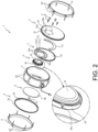
- Fig. 2 is an exploded perspective view of the drum 1
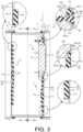
- Fig. 3 is a cross-sectional view of the drum 1 along line III-III of Fig. 1(b)
- Fig. 4(a) is a cross-sectional view of the drum 1 along line IVa-IVa of Fig. 3
- Fig. 4(b) is a cross-sectional view of the drum 1 along line IVb-IVb of Fig. 3
- an internal structure of the sensor part 4 is not shown, and the sensor part is shown with hatching.
- an inner cushion 71 and a double-sided tape 72 of a cushion 7 and an inner cushion 91 and a double-sided tape 92 of a cushion 9 are shown by broken lines.
- the striking surface head 3 includes a disc-shaped diaphragm 30 formed using a film made of a synthetic resin.
- the diaphragm 30 has a circular first through hole 30a for fitting the sensor part 4 (see Fig. 2 ) and a plurality of (five in the example) second through holes 30a surrounding the first through hole 30a.
- the second through hole 30b is a hole for press-fitting a fixture 5 which is used when the sensor part 4 is fixed to the diaphragm 30.
- the fixture 5 is a pin made of an elastomer (or rubber). That is, the sensor part 4 is fixed to the striking surface head 3 by fixing the sensor part 4 fitted in the first through hole 30a with the fixture 5 fitted in the second through hole 30b.
- the sensor part 4 is constituted by a disc 40 and a protrusion 41 that protrudes from a surface of the disc 40 (a surface on the diaphragm 30 side) and is formed in a disc shape having a diameter smaller than that of the disc 40.
- the disc 40 and the protrusion 41 are formed concentrically with each other.
- a plurality of (five in the example) press-fitting holes 40a are formed on an outer peripheral surface of the disc 40 at equal intervals in a circumferential direction.
- the press-fitting hole 40a is a hole into which a shaft 51 (see Fig. 3 ) of the fixture 5 is press-fitted.
- the fixture 5 is constituted by a disc-shaped head part 50 and the shaft 51 protruding in a thickness direction of the head part 50.
- the diameter of the head part 50 is formed to be larger than the diameter of the second through hole 30b of the striking surface head 3.
- the shaft 51 has an annulus 51a for latching the diaphragm 30 of the striking surface head 3 and a recess 51b for latching the press-fitting hole 40a of the sensor part 4.
- the annulus 51a protrudes in an annular shape with a space corresponding to a diaphragm thickness of the diaphragm 30 between the annulus and the head part 50, and the outer diameter of the annulus 51a is formed to be slightly larger than the diameter of the second through hole 30b of the diaphragm 30. Therefore, by press-fitting the annulus 51a into the second through hole 30b of the diaphragm 30, the diaphragm 30 is latched between the head part 50 and the annulus 51a.
- the recess 51b is a recess extending in a circumferential direction of the shaft 51, and in a region where the recess 51b is formed, the diameter of the shaft 51 is set to be the same as the inner diameter of the press-fitting hole 40a of the sensor part 4. Therefore, by press-fitting the shaft 51 into the press-fitting hole 40a of the sensor part 4, the disc 40 of the sensor part 4 is latched to the recess 51b. Accordingly, the sensor part 4 is installed on the striking surface head 3 by the fixture 5.
- both the frame 31 and the hoop 6 are formed in an annular shape, and a plurality of fastening target parts 60 are formed in the hoop 6 at equal intervals in the circumferential direction.
- a plurality of fastening parts 20 are formed on an outer peripheral surface of the shell 2 at positions corresponding to the fastening target parts 60, and the fastening target parts 60 of the hoop 6 can be screwed to the plurality of fastening parts 20.
- each of the hoop 6 and the frame 31 is formed to be slightly larger than the outer diameter of the shell 2. Therefore, in a state in which the hoop 6 is latched to the frame 31 disposed on the outer peripheral side of the shell 2, by screwing the fastening target parts 60 of the hoop 6 to the fastening parts 20 of the shell 2, tension is applied to the diaphragm 30 of the striking surface head 3. Accordingly, the performer can strike the sensor part 4, but the diaphragm 30 also vibrates when the sensor part 4 is struck. The vibration of the diaphragm 30 is damped by the cushion 7.
- the cushion 7 is affixed to a back surface (a surface opposite to the surface to be struck) of the diaphragm 30 of the striking surface head 3. As shown in Fig. 2 , the cushion 7 is constituted by a disc-shaped outer cushion 70 and the inner cushion 71 having a C shape.
- Both the outer cushion 70 and the inner cushion 71 are formed using a foamed synthetic resin of polyurethane foam, and have a predetermined cushioning property.
- the outer cushion 70 is partially adhered to the diaphragm 30 by the double-sided tape 72 (hereinafter referred to as "partial adhesion"), and the inner cushion 71 is entirely adhered to the diaphragm 30 by the double-sided tape (not shown). In entire adhesion, the entire surface of the inner cushion 71 is adhered to the diaphragm 30.
- the outer cushion 70 is affixed to the diaphragm 30 by the double-sided tape 72 in a state in which the inner cushion 71 is interposed between the outer cushion and the diaphragm 30. Then, the inner cushion 71 is disposed in a region surrounded by the double-sided tape 72 (the adhesion portion between the diaphragm 30 and the outer cushion 70). Accordingly, the inner cushion 71 is pressed against the diaphragm 30 by the outer cushion 70, and the inner cushion 71 is in a compressed state, and thus the vibration of the diaphragm 30 is easily damped by the inner cushion 71.
- the double-sided tape 72 (the adhesion portion between the diaphragm 30 and the outer cushion 70) and the adhesion portion of the inner cushion 71 become a vibration node of the diaphragm 30. Accordingly, a vibration region of the diaphragm 30 is divided, and thus a vibration amplitude of the diaphragm 30 can be easily reduced as compared with the case in which only the outer cushion 70 is partially adhered to the diaphragm 30, for example. Therefore, the vibration of the diaphragm 30 is easily damped by the cushion 7, and thus the sound generated when the diaphragm 30 of the striking surface head 3 is struck can be effectively reduced.
- the cushion 7 can also be provided only in a part of a region avoiding the sensor part 4, for example.
- the effect of damping the vibration by the cushion 7 is reduced, and thus, in the embodiment, the cushion 7 can be affixed to almost the entire region of the diaphragm 30.
- the diameter of the outer cushion 70 is formed to be slightly smaller than the diameter of the diaphragm 30 (the inner diameter of the shell 2), and as shown in Fig. 2 , the outer cushion 70 has a circular through hole 70a and a cutout 70b formed to cut out the edge portion of the through hole 70a.
- the through hole 70a is a portion for fitting the sensor part 4, and the cutout 70b is a portion for inserting the fixture 5.
- the through hole 70a is formed at a position eccentric from the center of the outer cushion 70, and a plurality of cutouts 70b are formed at equal intervals in the circumferential direction of the through hole 70a. That is, when the outer cushion 70 is affixed to the diaphragm 30, the through hole 70a of the outer cushion 70 is formed at a position overlapping the first through hole 30a of the diaphragm 30, and the cutouts 70b are formed at positions overlapping the second through holes 30b of the diaphragm 30. Further, the diameter of the through hole 70a is formed to be slightly larger than the diameter of the first through hole 30a of the diaphragm 30.
- the sensor part 4 can be installed on the diaphragm 30 of the striking surface head 3 in a state in which the protrusion 41 of the sensor part 4 is inserted into the through hole 70a of the outer cushion 70. That is, it is configured such that the sensor part 4 can be fixed to the diaphragm 30 through the through hole 70a of the outer cushion 70, and thus the outer cushion 70 can be affixed to almost the entire region of the diaphragm 30.
- the outer cushion 70 has not only a function of pressing the inner cushion 71 against the diaphragm 30 but also a function of damping the vibration by being in contact with the diaphragm 30, by affixing the outer cushion 70 to almost the entire region of the diaphragm 30, the vibration of the diaphragm 30 is easily damped by the outer cushion 70. Further, almost the entire region of the diaphragm 30 is a region that is 70% or more of the area (the vibration region) of the diaphragm 30.
- the through hole 70a or the cutouts 70b are formed in the outer cushion 70
- the diameter of the through hole 70a of the outer cushion 70 is formed to be larger than the diameter of the first through hole 30a of the diaphragm 30, and the width dimension of the cutout 70b in the circumferential direction of the through hole 70a is formed to be larger than the diameter of the second through hole 30b of the diaphragm 30. Therefore, positioning when the outer cushion 70 is affixed to the diaphragm 30 can be easily performed.
- the diameter of the through hole 70a of the outer cushion 70 is set to be smaller than the diameter of the disc 40 of the sensor part 4. Therefore, as shown in Fig. 3 , in a state in which the sensor part 4 is installed on the striking surface head 3, the periphery of the through hole 70a of the outer cushion 70 is fixed between the diaphragm 30 of the striking surface head 3 and the disc 40 of the sensor part 4 while interposed therebetween. Accordingly, it is possible to prevent the periphery of the through hole 70a from coming off the diaphragm 30.
- a gap is formed between an outer edge portion of the disc 40 of the sensor part 4 and the diaphragm 30, and the outer cushion 70 is interposed in the gap.
- a groove 40b recessed on a side opposite to the diaphragm 30 side is formed in the disc 40. Accordingly, the outer cushion 70 is interposed between the outer edge portion of the disc portion 40 and the diaphragm 30, and thus the outer cushion 70 is deformed to bite into the groove 40b of the disc 40. Therefore, it is possible to more effectively prevent the periphery of the through hole 70a from coming off the diaphragm 30.
- the double-sided tape 72 for adhering the outer cushion 70 to the diaphragm 30 includes a first adhesion part 72a for adhering the periphery of the through hole 70a of the outer cushion 70 to the diaphragm 30, and a second adhesion part 72b for adhering the outer edge of the outer cushion 70 to the diaphragm 30. Accordingly, it is possible to prevent the outer edge of the outer cushion 70 or the periphery of the through hole 70a from coming off the diaphragm 30.
- the vibration of the diaphragm 30 can be effectively damped by the outer cushion 70. Further, by preventing the outer cushion 70 from coming off, it is possible to prevent a pressing force of the inner cushion 71 against the diaphragm 30 from weakening, and thus the vibration of the diaphragm 30 can be effectively damped by the cushion 7.
- the drum 1 is provided such that a plurality of (two in the embodiment) arc-shaped first adhesion parts 72a surround the periphery of the sensor part 4, but it is possible to connect the plurality of first adhesion parts 72a to each other and to surround the sensor part 4 with one first adhesion part 72a.
- a plurality of (four in the embodiment) arc-shaped second adhesion parts 72b are provided over substantially the entire circumference of the outer edge of the outer cushion 70, but it is possible to connect the plurality of second adhesion parts 72b to each other and to provide one second adhesion part 72b over substantially the entire circumference of the outer edge of the outer cushion 70.
- the vibration amplitude of the diaphragm 30 is likely to increase in a region below the center of the striking surface head 3 (the diaphragm 30). Therefore, in the embodiment, the inner cushion 71 is adhered to the lower side of the center of the diaphragm 30, that is, to a side opposite to the sensor part 4 with the center of the diaphragm 30 interposed therebetween.
- the inner cushion 71 can be disposed in a region where the amplitude of the vibration of the diaphragm 30 is likely to increase (the vibration region where the amplitude is likely to increase can be divided), and thus the vibration in that region can be effectively damped by the cushion 7.
- the outer shape of the sensor part 4 (the disc 40) is formed in a circular shape in an axial direction of the drum 1, but the inner cushion 71 is formed in a curved shape that is convex in a direction away from the sensor part 4. That is, by disposing the circular sensor part 4 at a position eccentric from the center of the striking surface head 3 (the diaphragm 30), a substantially C-shaped region in which the sensor part 4 is not disposed is formed in the diaphragm 30, and the inner cushion 71 is also formed in a C shape along the region.
- the inner cushion 71 can be disposed over the region where the sensor part 4 is not disposed, and the vibration region where the amplitude is likely to increase can be divided in a radial direction by one inner cushion 71. Therefore, the vibration in the region where the sensor part 4 is not disposed can be effectively damped while the number of the inner cushions 71 to be disposed is minimized.
- the diaphragm 30 of the striking surface head 3 vibrates when the sensor part 4 is struck, but a resonant head 8 is fixed to the end of the shell 2 on a side opposite to the striking surface head 3, and thus the resonant head 8 also vibrates to resonate with the vibration of the striking surface head 3.
- the vibration of the resonant head 8 is damped by the cushion 9, and the configuration of the cushion 9 will be described below.
- the resonant head 8 includes a diaphragm 80 and a frame 81.
- the diaphragm 80 has the same configuration as the diaphragm 30 of the striking surface head 3 except that the first through hole 30a and the second through hole 30b (see Fig. 2 ) are not formed.
- a hoop 6 for fixing the resonant head 8 to the shell 2 has the same configuration as the hoop 6 for fixing the striking surface head 3.
- the resonant head 8 is fixed to the shell 2 by the same fixing structure as the striking surface head 3 described above, and a cushion 9 is affixed to a back surface (a surface on the striking surface head 3 side) of the diaphragm 80 of the resonant head 8.
- the cushion 9 is constituted by a disc-shaped outer cushion 90 and the inner cushion 91 formed in a disc shape having a diameter smaller than that of the outer cushion 90. Both the outer cushion 90 and the inner cushion 91 are formed using a foamed synthetic resin of polyurethane foam or the like, and have a predetermined cushioning property.
- the outer cushion 90 is partially adhered to the diaphragm 80 of the resonant head 8 by the double-sided tape 92 (see Fig. 3 ), and the inner cushion 91 is entirely adhered to the diaphragm 80 by the double-sided tape (not shown) in the same manner.
- the outer cushion 90 is affixed to the diaphragm 80 in a state in which the inner cushion 91 is interposed between the outer cushion and the diaphragm 80. Then, the inner cushion 91 is disposed in a region surrounded by the double-sided tape 92 (the adhesion portion between the diaphragm 80 and the outer cushion 90).
- the inner cushion 91 is pressed against the diaphragm 80, and thus a vibration region of the diaphragm 80 can be divided. Therefore, a vibration amplitude of the diaphragm 80 can be easily reduced, and thus the vibration of the diaphragm 80 is easily damped by the cushion 9.
- a plurality of (four in the embodiment) arc-shaped double-sided tapes 92 are provided on the drum 1 over substantially the entire circumference of the outer edge of the outer cushion 90, but the double-sided tapes 92 may be connected to each other and may be formed in a single annular shape.
- the vibration amplitude is likely to increase in a region where the sensor part 4 is not installed, and as shown in Fig. 4(b) , the sensor part 4 is not installed on the diaphragm 80 of the resonant head 8, and thus the vibration amplitude of the diaphragm 80 is likely to increase at the center of the diaphragm 80. Therefore, in the embodiment, the inner cushion 91 is adhered to the center of the diaphragm 80. Accordingly, the region where the vibration amplitude of the diaphragm 80 is likely to increase can be divided by the inner cushion 91, and thus the vibration in that region can be effectively damped by the cushion 9.
- the area of the outer cushion 90 is set to a size over almost the entire region of the diaphragm 80 of the resonant head 8, the vibration of the diaphragm 80 is easily damped by the cushion 9. Further, almost the entire region of the diaphragm 80 is a region that is 70% or more of the area (the vibration region) of the diaphragm 80.
- the inner cushion 91 is provided in the center of the outer cushion 90, and the outer edge of the outer cushion 90 is adhered to the diaphragm 80 by the double-sided tape 92, and thus the entire inner cushion 91 can be uniformly pressed toward the diaphragm 80.
- the entire inner cushion 91 can be more uniformly pressed toward the diaphragm 80.
- the outer cushions 70 and 90 and the inner cushions 71 and 91 are formed separately. Accordingly, the inner cushions 71 and 91 can be affixed to the diaphragm 30 and the diaphragm 80 first (a first step), and then the outer cushions 70 and 90 can be affixed to the diaphragm 30 and the diaphragm 80 (a second step). Therefore, the inner cushions 71 and 91 can be reliably affixed to the diaphragm 30 and the diaphragm 80 at desired positions (regions in which the amplitude of vibration is likely to increase).
- the outer cushions 70 and 90 and the inner cushions 71 and 91 are both formed of the same material (the same material and the same thickness), by cutting out the outer cushions 70 and 90 and the inner cushions 71 and 91 from a common sheet-shaped cushion material, the cushions 7 and 9 can be easily formed.
- the diaphragm 30 and the diaphragm 80 have only to be formed using a net-shaped (mesh-shaped) material in which synthetic fibers are knitted.
- the diaphragm 30 and the diaphragm 80 are formed in a net shape, it is difficult to obtain a feeling of striking when they are struck.
- the diaphragm 30 and the diaphragm 80 are formed using a film made of synthetic resin. That is, the diaphragm 30 and the diaphragm 80 are formed using a material having lower air permeability than the net-shaped material, and have substantially no air permeability. Therefore, it is easy to obtain a feeling of striking when the diaphragm 30 and the diaphragm 80 are struck.
- the drum 1 of the embodiment it is possible to obtain both a feeling of striking when the diaphragm 30 (the sensor part 4) and the diaphragm 80 are struck, and to accelerate the damping of the vibrations of the diaphragm 30 and the diaphragm 80.
- the drum 1 of the embodiment described above and drums of first to third comparative examples described below are used to compare the degrees of the damping of the volumes (effective values of sound pressure) when the striking surface head 3 is struck.
- the striking surface head 3 (the sensor part 4) is struck in a state in which the resonant head 8 is removed, and the striking sound is measured with a microphone disposed at a position 50 cm away from the striking surface head 3.
- the first comparative example is a drum having the same configuration as the drum 1 described above except that the cushion 7 is not affixed to the striking surface head 3.
- the second comparative example is a drum in which only the outer cushion 70 is entirely adhered to the striking surface head 3 of the drum of the first comparative example.
- Fig. 5(a) is a graph showing a result of a drum striking test of the first comparative example
- Fig. 5(b) is a graph showing a result of a drum striking test of the second comparative example.
- a vertical axis of Fig. 5 indicates the level of the amplitude (the volume) of the striking sound
- a horizontal axis thereof indicates the time.
- the scales of the vertical axes of Figs. 5(a) to 5(d) are the same.
- the result is that, in the drum of the second comparative example (see Fig. 5 (b) ) in which the outer cushion 70 is entirely adhered to the diaphragm 30, the damping of the volume generated when the diaphragm 30 of the striking surface head 3 is struck is slightly more accelerated than in the drum of the first comparative example (see Fig. 5(a) ) in which the cushion 7 is not installed on the diaphragm 30 of the striking surface head 3.
- the volume generated at the time of striking the striking surface head 3 of the second comparative example was reduced to the extent of 3 dB (if the volume measured in the first comparative example was 100%, the volume measured in the second comparative example was reduced to 70%).
- This result is considered to be due to the fact that, in the drum of the second comparative example, the weight of the diaphragm 30 of the striking surface head 3 was increased by adhering the outer cushion 70 thereto, and the vibration of the diaphragm 30 was restrained by the outer cushion 70.
- Fig. 5(c) is a graph showing a result of a drum striking test of the third comparative example.
- the third comparative example is a drum in which the outer cushion 70 is partially adhered to the diaphragm 30 of the striking surface head 3 of the drum of the second comparative example.
- the partial adhesion in the third comparative example as in the drum 1 described above, only the outer edge of the outer cushion 70 is adhered to the diaphragm 30 by the double-sided tape 92. That is, the drum of the third comparative example has the same configuration as the drum 1 of the embodiment except that the inner cushion 71 is omitted from the cushion 7 and only the outer cushion 70 is adhered to the diaphragm 30.
- the result is that, in the drum of the third comparative example in which only the outer cushion 70 is partially adhered, the damping of the volume generated when the diaphragm 30 of the striking surface head 3 is struck is more accelerated than in the drum of the second comparative example.
- the volume generated at the time of striking the striking surface head 3 of the third comparative example was reduced to the extent of 6 dB (if the volume measured in the first comparative example was 100%, the volume measured in the third comparative example was reduced to 50%).
- This result is considered to be due to the fact that, when the outer cushion 70 was entirely adhered as in the second comparative example, the outer cushion 70 and the diaphragm 30 of the striking surface head 3 vibrated integrally, whereas, in the third comparative example, the outer cushion 70 was entirely adhered, and thus the outer cushion 70 and the diaphragm 30 can vibrate with different behaviors.
- the result is that, in the drum 1 of the embodiment, the damping of the volume generated when the diaphragm 30 of the striking surface head 3 is struck is further accelerated than in the drum of the third comparative example.
- the volume generated at the time of striking the striking surface head 3 of the drum 1 of the embodiment was reduced to the extent of 9 dB (if the volume measured in the first comparative example was 100%, the volume measured in the embodiment was reduced to 35%).
- This result is considered to be due to the fact that the inner cushion 71 was pressed against the diaphragm 30 of the striking surface head 3 by the outer cushion 70, and thus the vibration region of the diaphragm 30 was divided and the vibration of the diaphragm 30 is easily damped, as described above.
- the inner cushions 71 and 91 are interposed between the outer cushions 70 and 90 and the diaphragms 30 and 80 of the striking surface head 3 and the resonant head 8, and thus the inner cushions 71 and 91 are pressed against the diaphragms 30 and 80. Therefore, the vibration regions of the diaphragms 30 and 80 are divided and the vibration amplitudes thereof can be easily reduced, and thus the vibrations of the diaphragms 30 and 80 can be effectively damped by the cushions 7 and 9.
- FIGs. 6(a) , 6(b) to 8(a) and 8(b) are cross-sectional views of drums 201, 301, and 401 showing first to third modification examples. Further, Figs. 6(a) , 6(b) to 8(a) and 8(b) show cross sections at a position corresponding to Figs. 4(a) and 4(b) .
- the drum 201 of the first modification example includes a cushion 207 that is affixed to the diaphragm 30 of the striking surface head 3 and a cushion 209 that is affixed to the diaphragm 80 of the resonant head 8.
- the cushion 207 has the same configuration as the cushion 7 described above except that the configuration of an inner cushion 271 is different, and the cushion 209 has the same configuration as the cushion 9 described above except that the configuration of a double-sided tape 292 is different.
- the inner cushion 271 of the cushion 207 is formed in a disc shape having a diameter smaller than that of the outer cushion 70 (the disc 40 of the sensor part 4), and the outer cushion 70 is affixed to the diaphragm 30 by the double-sided tape 72 in a state in which the inner cushion 271 is interposed between the outer cushion 70 and the diaphragm 30 of the striking surface head 3. Accordingly, the vibration region of the diaphragm 30 is divided and the vibration amplitude of the diaphragm 30 can be easily reduced, and thus the vibration of the diaphragm 30 can be effectively damped by the cushion 207.
- the inner cushion 271 is disposed on the lower side of the center of the diaphragm 30, that is, on a side opposite to the sensor part 4 with the center of the diaphragm 30 interposed therebetween, the inner cushion 271 can be provided in a region where the amplitude of the vibration of the diaphragm 30 is likely to increase (the vibration region where the amplitude is likely to increase can be divided). Therefore, the vibration in such a region can be effectively damped by the cushion 207.
- the inner cushion 271 is disposed on a side opposite to the sensor part 4 with the center of the diaphragm 30 interposed therebetween, the inner cushion 271 can be disposed at a position where the distance between the first adhesion part 72a and the second adhesion part 72b of the double-sided tape 72 in a radial direction of the sensor part 4 (the disc 40) is the longest. Accordingly, the inner cushion 271 can be disposed at a position where the vibration node of the diaphragm 30 is the longest, and thus the vibration of the diaphragm 30 can be effectively damped by one inner cushion 271.
- the double-sided tape 292 of the cushion 209 is formed radially around the inner cushion 91. That is, the double-sided tape 292 is formed in a linear shape extending in a radial direction of the outer cushion 90, and a plurality of double-sided tapes 292 (six in the embodiment) are provided side by side in a circumferential direction of the outer cushion 90. Accordingly, the distance between the double-sided tape 292 and the inner cushion 91 can be shortened as compared with the cushion 9 described above, and thus the inner cushion 91 can be strongly pressed against the diaphragm 80 of the resonant head 8. Therefore, the vibration of the diaphragm 80 can be effectively damped by the cushion 209.
- the outer cushion 90 can be adhered at a position (the center side of the diaphragm 80) where the amplitude of the diaphragm 80 of the resonant head 8 is likely to increase. Accordingly, the vibration of the diaphragm 80 can be effectively damped by the outer cushion 90 as well.
- the drum 301 of the second modification example includes a cushion 307 that is affixed to the diaphragm 30 of the striking surface head 3 and a cushion 309 that is affixed to the diaphragm 80 of the resonant head 8.
- the cushion 307 has the same configuration as the cushion 7 described above except that a plurality of inner cushions 271 described above are provided, and the cushion 309 has the same configuration as the cushion 9 described above except that the configuration of a double-sided tape 392 is different.
- a pair of inner cushions 271 of the cushion 307 is disposed on a side opposite to the sensor part 4 with the center of the diaphragm 30 interposed therebetween, and the pair of inner cushions 271 is provided side by side in the circumferential direction. Accordingly, the C-shaped region surrounded by the first adhesion part 72a and the second adhesion part 72b of the double-sided tape 72 can be divided in the radial direction by the pair of inner cushions 271.
- the inner cushion 271 can divide the region where the vibration amplitude of the diaphragm 30 is likely to increase while reducing the adhesion area of the inner cushion 271. Therefore, the vibration of the diaphragm 30 can be effectively damped by the cushion 307 while reducing the product cost of the cushion 307 (the drum 1).
- the double-sided tape 392 of the cushion 309 is formed in a linear shape extending vertically (in one direction) of the diaphragm 80 of the resonant head 8, and a plurality of linear double-sided tapes 392 are provided side by side in a left-right direction (a direction orthogonal to one direction) of the diaphragm 80). Accordingly, the entire outer cushion 90 can be uniformly affixed to the diaphragm 80 while preventing the outer cushion 90 from being entirely adhered.
- the adhesion area of the outer cushion 90 has only to be large, but if the adhesion area is too large, the diaphragm 80 and the outer cushion 90 is likely to vibrate integrally. Therefore, the adhesion area of the outer cushion 90 to the diaphragm 80 (the area of the double-sided tape 392) is preferably 50% or less of the area of the outer cushion 90.
- the drum 401 of the third modification example includes a cushion 407 that is affixed to the striking surface head 3 and a cushion 409 that is affixed to the resonant head 8.
- the cushion 407 has the same configuration as the cushion 307 described above except that a double-sided tape 472 is provided radially, and the cushion 409 has the same configuration as the cushion 9 described above except that the configuration of an inner cushion 491 is different.
- the double-sided tape 472 of the cushion 407 is formed radially around the center of the outer cushion 70. That is, the double-sided tape 472 is formed in a linear shape extending in a radial direction of the outer cushion 70, and a plurality of double-sided tapes 472 (seven in the example) are provided side by side in a circumferential direction of the outer cushion 70. Accordingly, the outer cushion 70 can be adhered to the region where the amplitude of the diaphragm 30 of the striking surface head 3 is likely to increase (the substantially C-shaped region where the sensor part 4 is not disposed), and thus the vibration of the diaphragm 30 can be effectively damped by the outer cushion 70 as well.
- the region where the amplitude of the diaphragm 30 is likely to increase can be divided into a plurality of regions by the double-sided tapes 472. Therefore, the vibration of the diaphragm 30 in such a region can be effectively damped by the cushion 407.
- the inner cushions 271 can be disposed in the vibration regions divided in the circumferential direction by the double-sided tapes 472. Accordingly, the vibration of the diaphragm 30 can be effectively damped by the cushion 407.
- the inner cushion 491 of the cushion 409 is formed in a linear shape extending to the left and right. Accordingly, the vibration region of the diaphragm 80 of the resonant head 8 can be divided into upper and lower parts, and thus the vibration of the diaphragm 80 can be effectively damped by the cushion 409.
- drum 1, 201, 301, or 401 is configured as a bass drum
- the disclosure is not necessarily limited to this.
- it may be configured as a snare or tom-tom drum.
- the sensor part 4 is provided on the striking surface head 3 of the drum 1, 201, 301, or 401 has been described, but the disclosure is not necessarily limited to this.
- the sensor part 4, and the first through hole 30a and the second through hole 30b of the diaphragm 30 of the striking surface head 3 may be omitted. That is, the drum 1, 201, 301, or 401 may be configured as an acoustic drum. Further, in a case in which the first through hole 30a and the second through hole 30b of the diaphragm 30 are omitted, the cushion 9, 209, 309, or 409 may be affixed to the diaphragm 30.
- the diaphragm 30 and the diaphragm 80 are formed using a material having lower air permeability than the net-shaped material, and a synthetic resin film is exemplified as an example of the material, but the disclosure is not necessarily limited to this.
- the diaphragm 30 and the diaphragm 80 may be formed using real leather. That is, the material having lower air permeability than the net-shaped material is a material that does not have holes that penetrate in a thickness direction of the drum head and has substantially no air permeability.
- the sensor part 4 including the disc 40 and the protrusion 41 has been illustrated, but the disclosure is not necessarily limited to this.
- other known attachments such as the attachment described in WO2017/038226 may be attached to the striking surface head 3 or the resonant head 8.
- the shape or affix region of the cushion has only to be appropriately set according to the shape and disposition of the attachment, and the cushion has only to be provided at a position avoiding the attachment.
- the adhesion with the double-sided tape has been exemplified as a method of joining the outer cushions 70 and 90 or the inner cushions 71, 271, 91, and 491 to the diaphragm 30 and the diaphragm 80, but the disclosure is not necessarily limited to this.
- a known joining method such as joining with a suture or an adhesive can be applied as long as the outer cushion or the inner cushion can be fixed to the diaphragm of the drum head.
- the area of the outer cushions 70 and 90 is 70% or more of the area of the diaphragm 30 and the diaphragm 80 has been described, but the disclosure is not necessarily limited to this.
- the area of the outer cushion has only to be at least 50% or more of the area of the diaphragm (the vibration region) of the drum head.
- the outer cushion 70 is fixed between the striking surface head 3 (the diaphragm 30) and the sensor part 4 (the disc 40) while interposed therebetween has been described, but the disclosure is not necessarily limited to this.
- the sensor part 4 and the outer cushion 70 may be in a non-contact structure.
- each of the outer cushion and the inner cushion can be appropriately set to a shape such as a polygon or an ellipse, or a shape combining straight lines and curves (for example, a semicircle).
- the case in which the outer cushions 70 and 90 and the inner cushions 71, 271, 91, and 491 are formed separately has been described, but the disclosure is not necessarily limited to this.
- the outer cushions 70 and 90 and the inner cushions 71, 271, 91, and 491 may be integrally formed.
- the outer cushions 70 and 90 and the inner cushions 71, 271, 91, and 491 are formed of the same material and the same thickness
- the disclosure is not necessarily limited to this.
- the outer cushions and the inner cushions may be formed of different materials or different thicknesses.
- the outer cushions 70 and 90 and the inner cushions 71, 271, 91, and 491 are formed using the foamed synthetic resin of polyurethane foam
- the disclosure is not necessarily limited to this.
- the cushions may be formed using other foamed synthetic resins (polyethylene foam, polyolefin foam, polyvinyl chloride foam, melamine foam, polyimide foam, and the like), or other rubbers or elastomers. That is, the materials of the outer cushions and the inner cushions can be appropriately set as long as they have a cushioning property for damping the vibration of the diaphragm of the drum head.
- the periphery of the through hole 70a of the outer cushion 70 is adhered by the first adhesion part 72a of the double-sided tape 72, but the disclosure is not necessarily limited to this.
- the first adhesion part 72a may be omitted.
- the double-sided tape 292 is formed in a linear shape extending in the radial direction in a case in which the plurality of double-sided tapes 472 and 292 is provided radially has been described, but the disclosure is not necessarily limited to this.
- the double-sided tapes 472 and 292 may be curved (bent) at a part of the drum head (the diaphragm) in the radial direction, or may have a shape in which the curving (bending) is repeated. That is, a "joint extending in the radial direction" is not limited to a joint extending in a linear shape in the radial direction.
Description
- The disclosure relates to a drum head and an attachment method of a cushion, and particularly to a drum head and an attachment method of a cushion capable of effectively reducing a sound generated when the drum head is struck.
- There is a technique for reducing the sound generated when a diaphragm of a drum head is struck by affixing a cushion having a cushioning property to the diaphragm. If the entire surface of the cushion is adhered to the diaphragm, the cushion and the diaphragm vibrate integrally, and thus the sound cannot be sufficiently reduced.
- On the other hand,
Patent Document 1 describes a technique of adhering an outer edge of a striking surface side mass imparting member 13 to the diaphragm of a drum head. As in this technique, by adhering only the outer edge of the cushion to the diaphragm, the diaphragm and the cushion can vibrate separately (with different behaviors) when the diaphragm is struck. Therefore, as compared with the case in which the entire surface of the cushion is adhered to the diaphragm, the sound generated when the diaphragm is struck is more likely to be reduced. - [Patent Document 1]
Japanese Patent Laid-Open No. 2014-056177 Fig. 1 )
US 8148619 B1 discloses a musical drum with a hollow shell having at least one opening and a drumhead with a tensioned membrane with a playing surface covering the opening, including an annular fixture mounted on a playing surface with the fixture having an outer concentric edge adjacent a flange member having an inner surface faced opposed to the playing surface, an inner concentric edge spaced apart from said playing surface and an area adjacent the inner concentric edge which defines an annular channel with the drumhead for receiving a damping member in fixed retained relation with the annular fixture. The annular fixture, including the damping member, is mounted to the playing surface by a series of incrementally spaced-apart non-adhesive means or non-adhesive means disposed in a continuous array provided for attaching the flange member to the playing surface.
US 4679479 A discloses an electronic drum including a relatively hard surface layer, a relatively hard base layer, a relatively hard coupling portion, and a detection element. The base layer is spaced apart from the surface layer by a predetermined distance. The coupling portion couples the surface layer to the base layer. The detection element is mounted on the base layer to detect striking of the surface layer.
US 2565225 A discloses a sound muffling pad for drummers comprising a relatively large bottom area of thin soft rubber to the top center region of which is secured an appreciable thicker rubber portion and a thin metal plate. The metal plate has approximately the same diameter as the thicker central rubber portion and is positioned between it and the larger area of rubber.WO 2019/180807 A1 discloses a sound damper with a sound damping member which has a contact surface for contacting a vibrating member and which has a through-hole formed having a first opening in the aforementioned contact surface, and a support member which supports the sound damping member and which enables the vibrating member and the contact surface to contact. The support member has an air hole which passes through the support member and which communicates with the through-hole in the sound damping member.
US 2019/213983 A1 discloses an electronic drum pad including a drum shell; a mesh head stretched at the upper opening of the drum shell; a hard-resin sheet disposed adjacent to the rear surface of the mesh head and having a ring shape with an opening made at a center thereof; a cloth disposed adjacent to the rear surface of the hard-resin sheet; a strike absorbing member disposed adjacent to the rear surface of the cloth and formed by overlaying a plurality of sheets; and a tray disposed adjacent to the rear surface of the strike absorbing member and fitted into the lower opening of the drum shell.
WO 2017/038226 A1 discloses a bass drum damper and a bass drum. The bass drum damper includes a sound insulating plate that covers a batter head of an acoustic bass drum generating a percussive sound when a beater of a foot pedal percusses a predetermined percussion location. The sound insulating plate includes a contact portion having an opening portion open for the percussion location for the beater and is in contact with the batter head, and a fixing portion provided at a circumferential edge of the contact portion and fixed to a hoop applying a tensile force to the batter head, or the batter head.
US 9257107 B1
US 9396712 B1 - In this type of drum head, there is a demand for a technique for more effectively reducing the sound generated when it is struck.
- The disclosure has been made according to the above-described demand and provides a drum head according to
claim 1, and an attachment method of a cushion according to claim 11, capable of effectively reducing the sound generated when the drum head is struck. - The present invention is provided by the appended claims. The following disclosure serves a better understanding of the present invention.
-
-
Fig. 1(a) is a perspective view of a drum according to an example, andFig. 1(b) is a front view of the drum. -
Fig. 2 is an exploded perspective view of the drum. -
Fig. 3 is a cross-sectional view of the drum along line III-III ofFig. 1(b) . -
Fig. 4(a) is a cross-sectional view of the drum along line IVa-IVa ofFig. 3 , andFig. 4(b) is a cross-sectional view of the drum along line IVb-IVb ofFig. 3 . -
Fig. 5(a) is a graph showing a result of a drum striking test of a first comparative example,Fig. 5(b) is a graph showing a result of a drum striking test of a second comparative example,Fig. 5(c) is a graph showing a result of a drum striking test of a third comparative example, andFig. 5(d) is a graph showing a result of a drum striking test of the embodiment. -
Figs. 6(a) and 6(b) are cross-sectional views of a drum showing a first modification example. -
Figs. 7(a) and 7(b) are cross-sectional view of a drum showing a second modification example. -
Figs. 8(a) and 8(b) are cross-sectional views of a drum showing a third modification example. - Hereinafter, preferred embodiments and examples will be described with reference to the accompanying drawings. First, the overall configuration of the
drum 1 will be described with reference toFig. 1. Fig. 1(a) is a perspective view of adrum 1 according to an example, andFig. 1(b) is a front view of thedrum 1. - As shown in
Fig. 1 , thedrum 1 is a percussion instrument (a bass drum) in which an end of acylindrical shell 2 is closed by astriking surface head 3. Thestriking surface head 3 is struck by afoot pedal 100. Thefoot pedal 100 strikes thestriking surface head 3 with abeater 111 that rotates in response to the depression of thepedal 110. - A
sensor part 4 is installed on a portion of thestriking surface head 3 which is struck by thebeater 111. Thesensor part 4 includes a sensor (not shown) for detecting vibration due to the striking by thebeater 111. Therefore, when the striking by thebeater 111 is detected by thesensor part 4, a musical sound signal based on the detection result is generated by a sound source (not shown). When the musical sound signal is output to an amplifier or a speaker (neither is shown), an electronic musical sound is emitted from the speaker. - That is, the
drum 1 is configured as an electronic drum, and thesensor part 4 is a striking position for a performer, but in thedrum 1 in which thesensor part 4 is not installed, thestriking surface head 3 is the striking position for the performer. - Next, a detailed configuration of the
drum 1 will be described with reference toFigs. 2 to 4(a) and4(b) .Fig. 2 is an exploded perspective view of thedrum 1, andFig. 3 is a cross-sectional view of thedrum 1 along line III-III ofFig. 1(b) .Fig. 4(a) is a cross-sectional view of thedrum 1 along line IVa-IVa ofFig. 3 , andFig. 4(b) is a cross-sectional view of thedrum 1 along line IVb-IVb ofFig. 3 . In addition, to simplify the drawing, inFig. 3 , an internal structure of thesensor part 4 is not shown, and the sensor part is shown with hatching. Further, inFig. 4 , aninner cushion 71 and a double-sided tape 72 of acushion 7 and aninner cushion 91 and a double-sided tape 92 of acushion 9 are shown by broken lines. - As shown in
Figs. 2 and3 , thestriking surface head 3 includes a disc-shaped diaphragm 30 formed using a film made of a synthetic resin. Thediaphragm 30 has a circular first throughhole 30a for fitting the sensor part 4 (seeFig. 2 ) and a plurality of (five in the example) second throughholes 30a surrounding the first throughhole 30a. The second throughhole 30b is a hole for press-fitting afixture 5 which is used when thesensor part 4 is fixed to thediaphragm 30. Thefixture 5 is a pin made of an elastomer (or rubber). That is, thesensor part 4 is fixed to thestriking surface head 3 by fixing thesensor part 4 fitted in the first throughhole 30a with thefixture 5 fitted in the second throughhole 30b. - Specifically, the
sensor part 4 is constituted by adisc 40 and aprotrusion 41 that protrudes from a surface of the disc 40 (a surface on thediaphragm 30 side) and is formed in a disc shape having a diameter smaller than that of thedisc 40. Thedisc 40 and theprotrusion 41 are formed concentrically with each other. - A plurality of (five in the example) press-fitting
holes 40a are formed on an outer peripheral surface of thedisc 40 at equal intervals in a circumferential direction. The press-fittinghole 40a is a hole into which a shaft 51 (seeFig. 3 ) of thefixture 5 is press-fitted. - As shown in
Fig. 3 , thefixture 5 is constituted by a disc-shapedhead part 50 and theshaft 51 protruding in a thickness direction of thehead part 50. The diameter of thehead part 50 is formed to be larger than the diameter of the second throughhole 30b of thestriking surface head 3. - The
shaft 51 has anannulus 51a for latching thediaphragm 30 of thestriking surface head 3 and arecess 51b for latching the press-fittinghole 40a of thesensor part 4. Theannulus 51a protrudes in an annular shape with a space corresponding to a diaphragm thickness of thediaphragm 30 between the annulus and thehead part 50, and the outer diameter of theannulus 51a is formed to be slightly larger than the diameter of the second throughhole 30b of thediaphragm 30. Therefore, by press-fitting theannulus 51a into the second throughhole 30b of thediaphragm 30, thediaphragm 30 is latched between thehead part 50 and theannulus 51a. - The
recess 51b is a recess extending in a circumferential direction of theshaft 51, and in a region where therecess 51b is formed, the diameter of theshaft 51 is set to be the same as the inner diameter of the press-fittinghole 40a of thesensor part 4. Therefore, by press-fitting theshaft 51 into the press-fittinghole 40a of thesensor part 4, thedisc 40 of thesensor part 4 is latched to therecess 51b. Accordingly, thesensor part 4 is installed on thestriking surface head 3 by thefixture 5. - Then, the
striking surface head 3 on which thesensor part 4 is installed is fixed to theshell 2 by ahoop 6. Aframe 31 formed of a metal or a resin material is connected (fixed) to an outer edge side of thediaphragm 30 of thestriking surface head 3. As shown inFig. 2 , both theframe 31 and thehoop 6 are formed in an annular shape, and a plurality offastening target parts 60 are formed in thehoop 6 at equal intervals in the circumferential direction. A plurality offastening parts 20 are formed on an outer peripheral surface of theshell 2 at positions corresponding to thefastening target parts 60, and thefastening target parts 60 of thehoop 6 can be screwed to the plurality offastening parts 20. - The diameter of each of the
hoop 6 and theframe 31 is formed to be slightly larger than the outer diameter of theshell 2. Therefore, in a state in which thehoop 6 is latched to theframe 31 disposed on the outer peripheral side of theshell 2, by screwing thefastening target parts 60 of thehoop 6 to thefastening parts 20 of theshell 2, tension is applied to thediaphragm 30 of thestriking surface head 3. Accordingly, the performer can strike thesensor part 4, but thediaphragm 30 also vibrates when thesensor part 4 is struck. The vibration of thediaphragm 30 is damped by thecushion 7. - The
cushion 7 is affixed to a back surface (a surface opposite to the surface to be struck) of thediaphragm 30 of thestriking surface head 3. As shown inFig. 2 , thecushion 7 is constituted by a disc-shapedouter cushion 70 and theinner cushion 71 having a C shape. - Both the
outer cushion 70 and theinner cushion 71 are formed using a foamed synthetic resin of polyurethane foam, and have a predetermined cushioning property. Theouter cushion 70 is partially adhered to thediaphragm 30 by the double-sided tape 72 (hereinafter referred to as "partial adhesion"), and theinner cushion 71 is entirely adhered to thediaphragm 30 by the double-sided tape (not shown). In entire adhesion, the entire surface of theinner cushion 71 is adhered to thediaphragm 30. - As shown in
Fig. 3 , theouter cushion 70 is affixed to thediaphragm 30 by the double-sided tape 72 in a state in which theinner cushion 71 is interposed between the outer cushion and thediaphragm 30. Then, theinner cushion 71 is disposed in a region surrounded by the double-sided tape 72 (the adhesion portion between thediaphragm 30 and the outer cushion 70). Accordingly, theinner cushion 71 is pressed against thediaphragm 30 by theouter cushion 70, and theinner cushion 71 is in a compressed state, and thus the vibration of thediaphragm 30 is easily damped by theinner cushion 71. - That is, by pressing the
inner cushion 71 against thediaphragm 30, the double-sided tape 72 (the adhesion portion between thediaphragm 30 and the outer cushion 70) and the adhesion portion of theinner cushion 71 become a vibration node of thediaphragm 30. Accordingly, a vibration region of thediaphragm 30 is divided, and thus a vibration amplitude of thediaphragm 30 can be easily reduced as compared with the case in which only theouter cushion 70 is partially adhered to thediaphragm 30, for example. Therefore, the vibration of thediaphragm 30 is easily damped by thecushion 7, and thus the sound generated when thediaphragm 30 of thestriking surface head 3 is struck can be effectively reduced. - In this way, in a case in which the vibration of the
diaphragm 30 of thestriking surface head 3 is damped by thecushion 7, thecushion 7 can also be provided only in a part of a region avoiding thesensor part 4, for example. However, in such a configuration, the effect of damping the vibration by thecushion 7 is reduced, and thus, in the embodiment, thecushion 7 can be affixed to almost the entire region of thediaphragm 30. - Specifically, the diameter of the
outer cushion 70 is formed to be slightly smaller than the diameter of the diaphragm 30 (the inner diameter of the shell 2), and as shown inFig. 2 , theouter cushion 70 has a circular throughhole 70a and acutout 70b formed to cut out the edge portion of the throughhole 70a. The throughhole 70a is a portion for fitting thesensor part 4, and thecutout 70b is a portion for inserting thefixture 5. - The through
hole 70a is formed at a position eccentric from the center of theouter cushion 70, and a plurality ofcutouts 70b are formed at equal intervals in the circumferential direction of the throughhole 70a. That is, when theouter cushion 70 is affixed to thediaphragm 30, the throughhole 70a of theouter cushion 70 is formed at a position overlapping the first throughhole 30a of thediaphragm 30, and thecutouts 70b are formed at positions overlapping the second throughholes 30b of thediaphragm 30. Further, the diameter of the throughhole 70a is formed to be slightly larger than the diameter of the first throughhole 30a of thediaphragm 30. - Accordingly, the
sensor part 4 can be installed on thediaphragm 30 of thestriking surface head 3 in a state in which theprotrusion 41 of thesensor part 4 is inserted into the throughhole 70a of theouter cushion 70. That is, it is configured such that thesensor part 4 can be fixed to thediaphragm 30 through the throughhole 70a of theouter cushion 70, and thus theouter cushion 70 can be affixed to almost the entire region of thediaphragm 30. Since theouter cushion 70 has not only a function of pressing theinner cushion 71 against thediaphragm 30 but also a function of damping the vibration by being in contact with thediaphragm 30, by affixing theouter cushion 70 to almost the entire region of thediaphragm 30, the vibration of thediaphragm 30 is easily damped by theouter cushion 70. Further, almost the entire region of thediaphragm 30 is a region that is 70% or more of the area (the vibration region) of thediaphragm 30. - On the other hand, in a case in which the through
hole 70a or thecutouts 70b are formed in theouter cushion 70, when theouter cushion 70 is affixed to thediaphragm 30 of thestriking surface head 3, it is necessary to position the throughhole 70a and thecutouts 70b with respect to the first throughhole 30a and the second throughholes 30b. However, in the embodiment, the diameter of the throughhole 70a of theouter cushion 70 is formed to be larger than the diameter of the first throughhole 30a of thediaphragm 30, and the width dimension of thecutout 70b in the circumferential direction of the throughhole 70a is formed to be larger than the diameter of the second throughhole 30b of thediaphragm 30. Therefore, positioning when theouter cushion 70 is affixed to thediaphragm 30 can be easily performed. - Further, the diameter of the through
hole 70a of theouter cushion 70 is set to be smaller than the diameter of thedisc 40 of thesensor part 4. Therefore, as shown inFig. 3 , in a state in which thesensor part 4 is installed on thestriking surface head 3, the periphery of the throughhole 70a of theouter cushion 70 is fixed between thediaphragm 30 of thestriking surface head 3 and thedisc 40 of thesensor part 4 while interposed therebetween. Accordingly, it is possible to prevent the periphery of the throughhole 70a from coming off thediaphragm 30. - Further, in a state in which the
sensor part 4 is fixed to thestriking surface head 3, a gap is formed between an outer edge portion of thedisc 40 of thesensor part 4 and thediaphragm 30, and theouter cushion 70 is interposed in the gap. Then, in a region where the gap is formed, agroove 40b recessed on a side opposite to thediaphragm 30 side is formed in thedisc 40. Accordingly, theouter cushion 70 is interposed between the outer edge portion of thedisc portion 40 and thediaphragm 30, and thus theouter cushion 70 is deformed to bite into thegroove 40b of thedisc 40. Therefore, it is possible to more effectively prevent the periphery of the throughhole 70a from coming off thediaphragm 30. - Further, as shown in
Fig. 2 , the double-sided tape 72 for adhering theouter cushion 70 to thediaphragm 30 includes afirst adhesion part 72a for adhering the periphery of the throughhole 70a of theouter cushion 70 to thediaphragm 30, and asecond adhesion part 72b for adhering the outer edge of theouter cushion 70 to thediaphragm 30. Accordingly, it is possible to prevent the outer edge of theouter cushion 70 or the periphery of the throughhole 70a from coming off thediaphragm 30. - In this way, by preventing the
outer cushion 70 from coming off thediaphragm 30 of thestriking surface head 3, the vibration of thediaphragm 30 can be effectively damped by theouter cushion 70. Further, by preventing theouter cushion 70 from coming off, it is possible to prevent a pressing force of theinner cushion 71 against thediaphragm 30 from weakening, and thus the vibration of thediaphragm 30 can be effectively damped by thecushion 7. - As shown in
Fig. 4(a) , thedrum 1 is provided such that a plurality of (two in the embodiment) arc-shapedfirst adhesion parts 72a surround the periphery of thesensor part 4, but it is possible to connect the plurality offirst adhesion parts 72a to each other and to surround thesensor part 4 with onefirst adhesion part 72a. Further, a plurality of (four in the embodiment) arc-shapedsecond adhesion parts 72b are provided over substantially the entire circumference of the outer edge of theouter cushion 70, but it is possible to connect the plurality ofsecond adhesion parts 72b to each other and to provide onesecond adhesion part 72b over substantially the entire circumference of the outer edge of theouter cushion 70. - Since the
sensor part 4 of thedrum 1 is disposed at an eccentric position above the center of the striking surface head 3 (the diaphragm 30), the vibration amplitude of thediaphragm 30 is likely to increase in a region below the center of the striking surface head 3 (the diaphragm 30). Therefore, in the embodiment, theinner cushion 71 is adhered to the lower side of the center of thediaphragm 30, that is, to a side opposite to thesensor part 4 with the center of thediaphragm 30 interposed therebetween. Accordingly, theinner cushion 71 can be disposed in a region where the amplitude of the vibration of thediaphragm 30 is likely to increase (the vibration region where the amplitude is likely to increase can be divided), and thus the vibration in that region can be effectively damped by thecushion 7. - Further, the outer shape of the sensor part 4 (the disc 40) is formed in a circular shape in an axial direction of the
drum 1, but theinner cushion 71 is formed in a curved shape that is convex in a direction away from thesensor part 4. That is, by disposing thecircular sensor part 4 at a position eccentric from the center of the striking surface head 3 (the diaphragm 30), a substantially C-shaped region in which thesensor part 4 is not disposed is formed in thediaphragm 30, and theinner cushion 71 is also formed in a C shape along the region. - Accordingly, the
inner cushion 71 can be disposed over the region where thesensor part 4 is not disposed, and the vibration region where the amplitude is likely to increase can be divided in a radial direction by oneinner cushion 71. Therefore, the vibration in the region where thesensor part 4 is not disposed can be effectively damped while the number of theinner cushions 71 to be disposed is minimized. - The description will return to
Figs. 2 and3 . As described above, thediaphragm 30 of thestriking surface head 3 vibrates when thesensor part 4 is struck, but aresonant head 8 is fixed to the end of theshell 2 on a side opposite to thestriking surface head 3, and thus theresonant head 8 also vibrates to resonate with the vibration of thestriking surface head 3. In the embodiment, the vibration of theresonant head 8 is damped by thecushion 9, and the configuration of thecushion 9 will be described below. - The
resonant head 8 includes adiaphragm 80 and aframe 81. Thediaphragm 80 has the same configuration as thediaphragm 30 of thestriking surface head 3 except that the first throughhole 30a and the second throughhole 30b (seeFig. 2 ) are not formed. Further, ahoop 6 for fixing theresonant head 8 to theshell 2 has the same configuration as thehoop 6 for fixing thestriking surface head 3. - The
resonant head 8 is fixed to theshell 2 by the same fixing structure as thestriking surface head 3 described above, and acushion 9 is affixed to a back surface (a surface on thestriking surface head 3 side) of thediaphragm 80 of theresonant head 8. Thecushion 9 is constituted by a disc-shapedouter cushion 90 and theinner cushion 91 formed in a disc shape having a diameter smaller than that of theouter cushion 90. Both theouter cushion 90 and theinner cushion 91 are formed using a foamed synthetic resin of polyurethane foam or the like, and have a predetermined cushioning property. - The
outer cushion 90 is partially adhered to thediaphragm 80 of theresonant head 8 by the double-sided tape 92 (seeFig. 3 ), and theinner cushion 91 is entirely adhered to thediaphragm 80 by the double-sided tape (not shown) in the same manner. Theouter cushion 90 is affixed to thediaphragm 80 in a state in which theinner cushion 91 is interposed between the outer cushion and thediaphragm 80. Then, theinner cushion 91 is disposed in a region surrounded by the double-sided tape 92 (the adhesion portion between thediaphragm 80 and the outer cushion 90). Accordingly, theinner cushion 91 is pressed against thediaphragm 80, and thus a vibration region of thediaphragm 80 can be divided. Therefore, a vibration amplitude of thediaphragm 80 can be easily reduced, and thus the vibration of thediaphragm 80 is easily damped by thecushion 9. - As shown in
Fig. 4(b) , a plurality of (four in the embodiment) arc-shaped double-sided tapes 92 are provided on thedrum 1 over substantially the entire circumference of the outer edge of theouter cushion 90, but the double-sided tapes 92 may be connected to each other and may be formed in a single annular shape. - As described above, in the
diaphragm 30 of the striking surface head 3 (seeFig. 4(a) ), the vibration amplitude is likely to increase in a region where thesensor part 4 is not installed, and as shown inFig. 4(b) , thesensor part 4 is not installed on thediaphragm 80 of theresonant head 8, and thus the vibration amplitude of thediaphragm 80 is likely to increase at the center of thediaphragm 80. Therefore, in the embodiment, theinner cushion 91 is adhered to the center of thediaphragm 80. Accordingly, the region where the vibration amplitude of thediaphragm 80 is likely to increase can be divided by theinner cushion 91, and thus the vibration in that region can be effectively damped by thecushion 9. - Further, since the area of the
outer cushion 90 is set to a size over almost the entire region of thediaphragm 80 of theresonant head 8, the vibration of thediaphragm 80 is easily damped by thecushion 9. Further, almost the entire region of thediaphragm 80 is a region that is 70% or more of the area (the vibration region) of thediaphragm 80. - The
inner cushion 91 is provided in the center of theouter cushion 90, and the outer edge of theouter cushion 90 is adhered to thediaphragm 80 by the double-sided tape 92, and thus the entireinner cushion 91 can be uniformly pressed toward thediaphragm 80. - Further, since substantially the entire circumference of the outer edge of the
outer cushion 90 is adhered to thediaphragm 80 by the double-sided tape 92, the entireinner cushion 91 can be more uniformly pressed toward thediaphragm 80. - By uniformly pressing the entire
inner cushion 91 against thediaphragm 80 of theresonant head 8, it is possible to suppress the occurrence of a weakly pressed portion on a part of theinner cushion 91, and thus the vibration of thediaphragm 80 can be effectively damped by thecushion 9. - In this way, in a case in which the
inner cushions diaphragm 30 and thediaphragm 80, it is also possible to form theouter cushions inner cushions inner cushions outer cushions outer cushions diaphragm 30 and thediaphragm 80, it is difficult to confirm the relative positions of theinner cushions diaphragm 30 and thediaphragm 80, and thus it is difficult to affix theinner cushions - On the other hand, in the embodiment, the
outer cushions inner cushions inner cushions diaphragm 30 and thediaphragm 80 first (a first step), and then theouter cushions diaphragm 30 and the diaphragm 80 (a second step). Therefore, theinner cushions diaphragm 30 and thediaphragm 80 at desired positions (regions in which the amplitude of vibration is likely to increase). - Further, since the
outer cushions inner cushions outer cushions inner cushions cushions - Here, if the damping of the vibrations of the
diaphragm 30 and thediaphragm 80 should be simply accelerated, thediaphragm 30 and thediaphragm 80 have only to be formed using a net-shaped (mesh-shaped) material in which synthetic fibers are knitted. However, if thediaphragm 30 and thediaphragm 80 are formed in a net shape, it is difficult to obtain a feeling of striking when they are struck. - On the other hand, in the embodiment, the
diaphragm 30 and thediaphragm 80 are formed using a film made of synthetic resin. That is, thediaphragm 30 and thediaphragm 80 are formed using a material having lower air permeability than the net-shaped material, and have substantially no air permeability. Therefore, it is easy to obtain a feeling of striking when thediaphragm 30 and thediaphragm 80 are struck. - On the other hand, since the
diaphragm 30 and thediaphragm 80 have substantially no air permeability, the vibrations of thediaphragm 30 and thediaphragm 80 are more difficult to damp than they would be if they had the net shape, but the vibrations are effectively damped by thecushions drum 1 of the embodiment, it is possible to obtain both a feeling of striking when the diaphragm 30 (the sensor part 4) and thediaphragm 80 are struck, and to accelerate the damping of the vibrations of thediaphragm 30 and thediaphragm 80. - Next, with reference to
Fig. 5 , the result of a striking test on the striking surface head 3 (the sensor part 4) performed using thedrum 1 configured as described above will be described. In this striking test, thedrum 1 of the embodiment described above and drums of first to third comparative examples described below are used to compare the degrees of the damping of the volumes (effective values of sound pressure) when thestriking surface head 3 is struck. In all of the drums of the embodiment and the first to third comparative examples, the striking surface head 3 (the sensor part 4) is struck in a state in which theresonant head 8 is removed, and the striking sound is measured with a microphone disposed at aposition 50 cm away from thestriking surface head 3. - The first comparative example is a drum having the same configuration as the
drum 1 described above except that thecushion 7 is not affixed to thestriking surface head 3. The second comparative example is a drum in which only theouter cushion 70 is entirely adhered to thestriking surface head 3 of the drum of the first comparative example. -
Fig. 5(a) is a graph showing a result of a drum striking test of the first comparative example, andFig. 5(b) is a graph showing a result of a drum striking test of the second comparative example. A vertical axis ofFig. 5 indicates the level of the amplitude (the volume) of the striking sound, and a horizontal axis thereof indicates the time. Further, the scales of the vertical axes ofFigs. 5(a) to 5(d) are the same. - As shown in
Figs. 5(a) and 5(b) , the result is that, in the drum of the second comparative example (seeFig. 5 (b) ) in which theouter cushion 70 is entirely adhered to thediaphragm 30, the damping of the volume generated when thediaphragm 30 of thestriking surface head 3 is struck is slightly more accelerated than in the drum of the first comparative example (seeFig. 5(a) ) in which thecushion 7 is not installed on thediaphragm 30 of thestriking surface head 3. - Specifically, as compared with the volume at the time of striking the
striking surface head 3 of the first comparative example, the volume generated at the time of striking thestriking surface head 3 of the second comparative example was reduced to the extent of 3 dB (if the volume measured in the first comparative example was 100%, the volume measured in the second comparative example was reduced to 70%). This result is considered to be due to the fact that, in the drum of the second comparative example, the weight of thediaphragm 30 of thestriking surface head 3 was increased by adhering theouter cushion 70 thereto, and the vibration of thediaphragm 30 was restrained by theouter cushion 70. -
Fig. 5(c) is a graph showing a result of a drum striking test of the third comparative example. The third comparative example is a drum in which theouter cushion 70 is partially adhered to thediaphragm 30 of thestriking surface head 3 of the drum of the second comparative example. In the partial adhesion in the third comparative example, as in thedrum 1 described above, only the outer edge of theouter cushion 70 is adhered to thediaphragm 30 by the double-sided tape 92. That is, the drum of the third comparative example has the same configuration as thedrum 1 of the embodiment except that theinner cushion 71 is omitted from thecushion 7 and only theouter cushion 70 is adhered to thediaphragm 30. - As shown in
Fig. 5(c) , the result is that, in the drum of the third comparative example in which only theouter cushion 70 is partially adhered, the damping of the volume generated when thediaphragm 30 of thestriking surface head 3 is struck is more accelerated than in the drum of the second comparative example. - Specifically, as compared with the volume at the time of striking the
striking surface head 3 of the first comparative example, the volume generated at the time of striking thestriking surface head 3 of the third comparative example was reduced to the extent of 6 dB (if the volume measured in the first comparative example was 100%, the volume measured in the third comparative example was reduced to 50%). This result is considered to be due to the fact that, when theouter cushion 70 was entirely adhered as in the second comparative example, theouter cushion 70 and thediaphragm 30 of thestriking surface head 3 vibrated integrally, whereas, in the third comparative example, theouter cushion 70 was entirely adhered, and thus theouter cushion 70 and thediaphragm 30 can vibrate with different behaviors. - As shown in
Fig. 5(d) , the result is that, in thedrum 1 of the embodiment, the damping of the volume generated when thediaphragm 30 of thestriking surface head 3 is struck is further accelerated than in the drum of the third comparative example. - Specifically, as compared with the volume at the time of striking the
striking surface head 3 of the first comparative example, the volume generated at the time of striking thestriking surface head 3 of thedrum 1 of the embodiment was reduced to the extent of 9 dB (if the volume measured in the first comparative example was 100%, the volume measured in the embodiment was reduced to 35%). This result is considered to be due to the fact that theinner cushion 71 was pressed against thediaphragm 30 of thestriking surface head 3 by theouter cushion 70, and thus the vibration region of thediaphragm 30 was divided and the vibration of thediaphragm 30 is easily damped, as described above. - As described above, according to the
drum 1 of the embodiment, theinner cushions outer cushions diaphragms striking surface head 3 and theresonant head 8, and thus theinner cushions diaphragms diaphragms diaphragms cushions - Next, modification examples of the
drum 1 will be described with reference toFigs. 6(a) ,6(b) to 8(a) and8(b) . The same portions as those of thedrum 1 described above are designated by the same reference numerals, and the description thereof will be omitted.Figs. 6(a) ,6(b) to 8(a) and8(b) are cross-sectional views ofdrums Figs. 6(a) ,6(b) to 8(a) and8(b) show cross sections at a position corresponding toFigs. 4(a) and 4(b) . - As shown in
Figs. 6(a) and 6(b) , thedrum 201 of the first modification example includes acushion 207 that is affixed to thediaphragm 30 of thestriking surface head 3 and acushion 209 that is affixed to thediaphragm 80 of theresonant head 8. Thecushion 207 has the same configuration as thecushion 7 described above except that the configuration of aninner cushion 271 is different, and thecushion 209 has the same configuration as thecushion 9 described above except that the configuration of a double-sided tape 292 is different. - The
inner cushion 271 of thecushion 207 is formed in a disc shape having a diameter smaller than that of the outer cushion 70 (thedisc 40 of the sensor part 4), and theouter cushion 70 is affixed to thediaphragm 30 by the double-sided tape 72 in a state in which theinner cushion 271 is interposed between theouter cushion 70 and thediaphragm 30 of thestriking surface head 3. Accordingly, the vibration region of thediaphragm 30 is divided and the vibration amplitude of thediaphragm 30 can be easily reduced, and thus the vibration of thediaphragm 30 can be effectively damped by thecushion 207. - Since the
inner cushion 271 is disposed on the lower side of the center of thediaphragm 30, that is, on a side opposite to thesensor part 4 with the center of thediaphragm 30 interposed therebetween, theinner cushion 271 can be provided in a region where the amplitude of the vibration of thediaphragm 30 is likely to increase (the vibration region where the amplitude is likely to increase can be divided). Therefore, the vibration in such a region can be effectively damped by thecushion 207. - Further, since the
inner cushion 271 is disposed on a side opposite to thesensor part 4 with the center of thediaphragm 30 interposed therebetween, theinner cushion 271 can be disposed at a position where the distance between thefirst adhesion part 72a and thesecond adhesion part 72b of the double-sided tape 72 in a radial direction of the sensor part 4 (the disc 40) is the longest. Accordingly, theinner cushion 271 can be disposed at a position where the vibration node of thediaphragm 30 is the longest, and thus the vibration of thediaphragm 30 can be effectively damped by oneinner cushion 271. - The double-
sided tape 292 of thecushion 209 is formed radially around theinner cushion 91. That is, the double-sided tape 292 is formed in a linear shape extending in a radial direction of theouter cushion 90, and a plurality of double-sided tapes 292 (six in the embodiment) are provided side by side in a circumferential direction of theouter cushion 90. Accordingly, the distance between the double-sided tape 292 and theinner cushion 91 can be shortened as compared with thecushion 9 described above, and thus theinner cushion 91 can be strongly pressed against thediaphragm 80 of theresonant head 8. Therefore, the vibration of thediaphragm 80 can be effectively damped by thecushion 209. - Further, by providing, in the circumferential direction, a plurality of double-
sided tapes 292 that extend in the radial direction of theouter cushion 90, theouter cushion 90 can be adhered at a position (the center side of the diaphragm 80) where the amplitude of thediaphragm 80 of theresonant head 8 is likely to increase. Accordingly, the vibration of thediaphragm 80 can be effectively damped by theouter cushion 90 as well. - As shown in
Figs. 7(a) and 7(b) , thedrum 301 of the second modification example includes acushion 307 that is affixed to thediaphragm 30 of thestriking surface head 3 and acushion 309 that is affixed to thediaphragm 80 of theresonant head 8. Thecushion 307 has the same configuration as thecushion 7 described above except that a plurality ofinner cushions 271 described above are provided, and thecushion 309 has the same configuration as thecushion 9 described above except that the configuration of a double-sided tape 392 is different. - A pair of
inner cushions 271 of thecushion 307 is disposed on a side opposite to thesensor part 4 with the center of thediaphragm 30 interposed therebetween, and the pair ofinner cushions 271 is provided side by side in the circumferential direction. Accordingly, the C-shaped region surrounded by thefirst adhesion part 72a and thesecond adhesion part 72b of the double-sided tape 72 can be divided in the radial direction by the pair ofinner cushions 271. - Therefore, as compared with the
cushion 7 described above, theinner cushion 271 can divide the region where the vibration amplitude of thediaphragm 30 is likely to increase while reducing the adhesion area of theinner cushion 271. Therefore, the vibration of thediaphragm 30 can be effectively damped by thecushion 307 while reducing the product cost of the cushion 307 (the drum 1). - The double-
sided tape 392 of thecushion 309 is formed in a linear shape extending vertically (in one direction) of thediaphragm 80 of theresonant head 8, and a plurality of linear double-sided tapes 392 are provided side by side in a left-right direction (a direction orthogonal to one direction) of the diaphragm 80). Accordingly, the entireouter cushion 90 can be uniformly affixed to thediaphragm 80 while preventing theouter cushion 90 from being entirely adhered. - To uniformly affix the entire
outer cushion 90 to thediaphragm 80, the adhesion area of theouter cushion 90 has only to be large, but if the adhesion area is too large, thediaphragm 80 and theouter cushion 90 is likely to vibrate integrally. Therefore, the adhesion area of theouter cushion 90 to the diaphragm 80 (the area of the double-sided tape 392) is preferably 50% or less of the area of theouter cushion 90. - As shown in
Figs. 8(a) and 8(b) , thedrum 401 of the third modification example includes acushion 407 that is affixed to thestriking surface head 3 and acushion 409 that is affixed to theresonant head 8. Thecushion 407 has the same configuration as thecushion 307 described above except that a double-sided tape 472 is provided radially, and thecushion 409 has the same configuration as thecushion 9 described above except that the configuration of aninner cushion 491 is different. - The double-
sided tape 472 of thecushion 407 is formed radially around the center of theouter cushion 70. That is, the double-sided tape 472 is formed in a linear shape extending in a radial direction of theouter cushion 70, and a plurality of double-sided tapes 472 (seven in the example) are provided side by side in a circumferential direction of theouter cushion 70. Accordingly, theouter cushion 70 can be adhered to the region where the amplitude of thediaphragm 30 of thestriking surface head 3 is likely to increase (the substantially C-shaped region where thesensor part 4 is not disposed), and thus the vibration of thediaphragm 30 can be effectively damped by theouter cushion 70 as well. - Further, by providing, in the circumferential direction, a plurality of double-
sided tapes 472 that extend in the radial direction of theouter cushion 70, the region where the amplitude of thediaphragm 30 is likely to increase (the substantially C-shaped region where thesensor part 4 is not disposed) can be divided into a plurality of regions by the double-sided tapes 472. Therefore, the vibration of thediaphragm 30 in such a region can be effectively damped by thecushion 407. - Since a pair of
inner cushions 271 are provided between the plurality of double-sided tapes 472 arranged in the circumferential direction, theinner cushions 271 can be disposed in the vibration regions divided in the circumferential direction by the double-sided tapes 472. Accordingly, the vibration of thediaphragm 30 can be effectively damped by thecushion 407. - The
inner cushion 491 of thecushion 409 is formed in a linear shape extending to the left and right. Accordingly, the vibration region of thediaphragm 80 of theresonant head 8 can be divided into upper and lower parts, and thus the vibration of thediaphragm 80 can be effectively damped by thecushion 409. - The above description has been made based on the above-described embodiment, but the disclosure is not limited to the above-described embodiment, and it is easily inferred that various improvements and modifications can be made wherein the invention is provided by the appended claims.
- In the above-described embodiment, the case where the
drum - In the above-described embodiment, the cases where the
sensor part 4 is provided on thestriking surface head 3 of thedrum sensor part 4, and the first throughhole 30a and the second throughhole 30b of thediaphragm 30 of thestriking surface head 3 may be omitted. That is, thedrum hole 30a and the second throughhole 30b of thediaphragm 30 are omitted, thecushion diaphragm 30. - In the above-described embodiment, the
diaphragm 30 and thediaphragm 80 are formed using a material having lower air permeability than the net-shaped material, and a synthetic resin film is exemplified as an example of the material, but the disclosure is not necessarily limited to this. For example, thediaphragm 30 and thediaphragm 80 may be formed using real leather. That is, the material having lower air permeability than the net-shaped material is a material that does not have holes that penetrate in a thickness direction of the drum head and has substantially no air permeability. - In the above-described embodiment, as an example of an attachment that is attached to the
striking surface head 3, thesensor part 4 including thedisc 40 and theprotrusion 41 has been illustrated, but the disclosure is not necessarily limited to this. For example, other known attachments such as the attachment described inWO2017/038226 may be attached to thestriking surface head 3 or theresonant head 8. The shape or affix region of the cushion has only to be appropriately set according to the shape and disposition of the attachment, and the cushion has only to be provided at a position avoiding the attachment. - In the above-described embodiment, the adhesion with the double-sided tape has been exemplified as a method of joining the
outer cushions inner cushions diaphragm 30 and thediaphragm 80, but the disclosure is not necessarily limited to this. For example, as such a joining method, a known joining method such as joining with a suture or an adhesive can be applied as long as the outer cushion or the inner cushion can be fixed to the diaphragm of the drum head. - In the above-described embodiment, the case in which the area of the
outer cushions diaphragm 30 and thediaphragm 80 has been described, but the disclosure is not necessarily limited to this. For example, the area of the outer cushion has only to be at least 50% or more of the area of the diaphragm (the vibration region) of the drum head. - In the above-described embodiment, the case in which the
outer cushion 70 is fixed between the striking surface head 3 (the diaphragm 30) and the sensor part 4 (the disc 40) while interposed therebetween has been described, but the disclosure is not necessarily limited to this. For example, thesensor part 4 and theouter cushion 70 may be in a non-contact structure. - In the above-described embodiment, the case in which the
outer cushions inner cushions - In the above-described embodiment, the case in which the
outer cushions inner cushions outer cushions inner cushions - In the above-described embodiment, the case in which the
outer cushions inner cushions - In the above-described embodiment, the case in which the
outer cushions inner cushions - In the above-described embodiment, the periphery of the through
hole 70a of theouter cushion 70 is adhered by thefirst adhesion part 72a of the double-sided tape 72, but the disclosure is not necessarily limited to this. For example, thefirst adhesion part 72a may be omitted. - In the above-described embodiment, the case in which the double-
sided tape 292 is formed in a linear shape extending in the radial direction in a case in which the plurality of double-sided tapes sided tapes -
- 3 Striking surface head (drum head)
- 30 Diaphragm
- 4 Sensor part (attachment)
- 7, 207, 307, 407, 9, 209, 309, 409 Cushion
- 70, 90 Outer cushion
- 70a Through hole
- 71, 271, 91, 491 Inner cushion
- 72, 472, 92, 292, 392 Double-sided tape (joint)
- 72a First adhesion part (first joint)
- 72b Second adhesion part (second joint)
- 8 Resonant head (drum head)
- 80 Diaphragm
Claims (14)
- A drum head (3) comprising:a diaphragm (30);a first cushion (70) that is joined to the diaphragm (30) and has a predetermined cushioning property;a second cushion (71, 271) that is interposed between the first cushion (70) and the diaphragm (30) and has a predetermined cushioning property; anda plurality of joints (72a, 72b, 92, 292, 472) , each one of the plurality of joints being configured to join the first cushion (70) directly to the diaphragm (30) in a state in which the second cushion (71, 271) is pressed against the diaphragm (30) by the first cushion (70), wherein the joints (72a, 72b, 92, 292, 472) are configured to be disposed on the diaphragm (30) and to surround the second cushion (71, 271),the drum head (3) being characterized in that:
each of the joints (72a, 72b, 92, 292, 472) is disposed on a surface of the diaphragm (30) on a vibration region of the diaphragm (30) and on a surface of the first cushion (70), and each of the joints (72a, 72b, 92, 292, 472) is disposed between the first cushion (70) and the diaphragm (30). - The drum head (3) according to claim 1, wherein the first cushion (70) and the second cushion (71, 271) are formed separately.
- The drum head (3) according to claim 1 or 2, wherein the second cushion (71, 271) is provided in a center side of the diaphragm (30) and the first cushion (70).
- The drum head (3) according to claim 3,
wherein the joints (72b) join an outer edge of the first cushion (70) to the diaphragm (30). - The drum head (3) according to claim 4, wherein each one of the plurality of the joints (292, 472) extends in a radial direction of the diaphragm (30) and the joints (292, 472) are provided in a circumferential direction of the diaphragm (30).
- The drum head (3) according to claim 4, wherein the joints (72b) join the outer edge of the first cushion (70) to the diaphragm (30) over substantially an entire circumference of the first cushion (70).
- The drum head (3) according to any one of claims 1 to 3, further comprising:an attachment (4) that is attached to the diaphragm (30),wherein the first cushion (70) comprises a through hole (70a) formed at a position corresponding to disposition of the attachment (4), andwherein the attachment (4) is configured to be fixed to the diaphragm (30) through the through hole (70a).
- The drum head (3) according to claim 7,wherein the attachment (4) is disposed at a position eccentric from a center of the diaphragm (30), andwherein the second cushion (70) is provided on a side opposite to the attachment (4) with the center of the diaphragm (30) interposed between the attachment (4) and the second cushion (71).
- The drum head (3) according to claim 8,wherein an outer shape of the attachment (4) is formed in a circular shape, andwherein the second cushion (71) is formed in a curved shape that is convex in a direction away from the attachment (4).
- The drum head (3) according to any one of claims 1 to 3, wherein each one of the plurality of the joints (292, 472) extends in a radial direction of the diaphragm (30) and the joints (292, 472) are arranged in a circumferential direction of the diaphragm (30).
- An attachment method of a cushion in a drum head (3), the drum head (3) comprising a diaphragm (4); and the cushion comprising a first cushion (70) and a second cushion (71) which are joined to the diaphragm (30) and have a predetermined cushioning property, wherein the second cushion is interposed between the first cushion (70) and the diaphragm (30),
the method comprising:a first step of joining the second cushion (71) to the diaphragm (30); anda second step of, after the first step, joining the first cushion (70) to the diaphragm (30) by pressing the second cushion (71) against the diaphragm (30) by the first cushion (70),whereinthe second step of joining the first cushion (70) to the diaphragm (30) comprises adhering the first cushion (70) directly to the diaphragm (30) using each of a plurality of joints (72a, 72b, 92, 292, 472); andthe plurality of joints (72a, 72b, 92, 292, 472) are configured to be disposed on the diaphragm (30) and to surround the second cushion (71, 271),the attachment method being characterized in thateach of the joints (72a, 72b, 92, 292, 472) is disposed on a surface of the diaphragm (30) on a vibration region of the diaphragm (30) and on a surface of the first cushion (70), and each of the joints (72a, 72b, 92, 292, 472) is disposed between the first cushion (70) and the diaphragm (30). - The attachment method of a cushion according to claim 11, wherein, in the first step, the second cushion (71) is provided on a center side of the diaphragm (30) and the first cushion (70).
- The attachment method of a cushion according to claim 12,
wherein, in the second step, an outer edge of the first cushion (70) is joined to the diaphragm (30). - The attachment method of a cushion according to claim 13, wherein, in the second step, a double-sided tape (72) is formed in a linear shape extending in a radial direction of the diaphragm (30) and a plurality of the double-sided tapes (72) are provided in a circumferential direction of the first cushion (70), to join the outer cushion (70) to the diaphragm (30).
Applications Claiming Priority (1)
| Application Number | Priority Date | Filing Date | Title |
|---|---|---|---|
| JP2019234965A JP2021103257A (en) | 2019-12-25 | 2019-12-25 | Attaching method of drum head and cushion |
Publications (2)
| Publication Number | Publication Date |
|---|---|
| EP3843082A1 EP3843082A1 (en) | 2021-06-30 |
| EP3843082B1 true EP3843082B1 (en) | 2023-10-18 |
Family
ID=73654641
Family Applications (1)
| Application Number | Title | Priority Date | Filing Date |
|---|---|---|---|
| EP20210857.7A Active EP3843082B1 (en) | 2019-12-25 | 2020-12-01 | Drum head and attachment method of cushion |
Country Status (4)
| Country | Link |
|---|---|
| US (1) | US20210201860A1 (en) |
| EP (1) | EP3843082B1 (en) |
| JP (1) | JP2021103257A (en) |
| CN (1) | CN113112974A (en) |
Citations (2)
| Publication number | Priority date | Publication date | Assignee | Title |
|---|---|---|---|---|
| US9257107B1 (en) * | 2014-10-24 | 2016-02-09 | Remo, Inc. | Musical drumhead with tonal modification |
| US9396712B1 (en) * | 2014-10-23 | 2016-07-19 | Ronn Dunnett | Multi layer drumhead with non-concentric inner layer |
Family Cites Families (9)
| Publication number | Priority date | Publication date | Assignee | Title |
|---|---|---|---|---|
| US2565225A (en) * | 1949-10-05 | 1951-08-21 | William D Gladstone | Appliance for musical instruments |
| US4227049A (en) * | 1978-11-27 | 1980-10-07 | Thomson Ian W | Audio system for isolating sounds from individual components of drum set-up for selectively mixing |
| JPS61251900A (en) * | 1985-05-01 | 1986-11-08 | ヤマハ株式会社 | Pad for electronic drum |
| JP5163071B2 (en) * | 2007-11-20 | 2013-03-13 | ヤマハ株式会社 | Electronic percussion instrument |
| US8148619B1 (en) * | 2011-01-12 | 2012-04-03 | Remo, Inc. | Drum damping fixture |
| JP5747884B2 (en) | 2012-09-13 | 2015-07-15 | ヤマハ株式会社 | Bass drum |
| US10163426B2 (en) | 2015-09-04 | 2018-12-25 | Roland Corporation | Bass drum damper and bass drum |
| JP6646690B2 (en) * | 2018-01-11 | 2020-02-14 | 株式会社コルグ | Electronic drum pad |
| CN111868819B (en) * | 2018-03-20 | 2024-01-30 | 雅马哈株式会社 | Mute apparatus, mute method, and vibration detection apparatus |
-
2019
- 2019-12-25 JP JP2019234965A patent/JP2021103257A/en active Pending
-
2020
- 2020-11-26 CN CN202011347925.5A patent/CN113112974A/en active Pending
- 2020-12-01 EP EP20210857.7A patent/EP3843082B1/en active Active
- 2020-12-02 US US17/109,148 patent/US20210201860A1/en active Pending
Patent Citations (2)
| Publication number | Priority date | Publication date | Assignee | Title |
|---|---|---|---|---|
| US9396712B1 (en) * | 2014-10-23 | 2016-07-19 | Ronn Dunnett | Multi layer drumhead with non-concentric inner layer |
| US9257107B1 (en) * | 2014-10-24 | 2016-02-09 | Remo, Inc. | Musical drumhead with tonal modification |
Also Published As
| Publication number | Publication date |
|---|---|
| JP2021103257A (en) | 2021-07-15 |
| US20210201860A1 (en) | 2021-07-01 |
| CN113112974A (en) | 2021-07-13 |
| EP3843082A1 (en) | 2021-06-30 |
Similar Documents
| Publication | Publication Date | Title |
|---|---|---|
| US9190040B2 (en) | Bass drum | |
| US6525249B1 (en) | Drumhead and muting structure for acoustic and electronic percussion instruments | |
| JP3933566B2 (en) | Electronic percussion instrument and vibration detection device | |
| TWI584267B (en) | Detachable electronic drum | |
| US8916759B2 (en) | Acoustic drum | |
| EP1837860A2 (en) | Electronic percussion instrument | |
| US9129585B2 (en) | Electronic percussion instrument | |
| US7476794B2 (en) | Sound modification system | |
| JP4898035B2 (en) | Externally mounted adjustable damping system for drum heads | |
| US10163426B2 (en) | Bass drum damper and bass drum | |
| JP6646690B2 (en) | Electronic drum pad | |
| CN102592575A (en) | Improver drum | |
| US20140260918A1 (en) | Electronic percussion instrument | |
| US20140260917A1 (en) | Electronic percussion instrument | |
| US10777179B2 (en) | Electronic percussion instrument | |
| JPH09244633A (en) | Electronic drum pad | |
| EP3843082B1 (en) | Drum head and attachment method of cushion | |
| JP2018169628A (en) | Electronic percussion instrument | |
| JP2023079668A (en) | Drum head and tensile force providing method | |
| WO2020174688A1 (en) | Detection device, percussion instrument, and detection method | |
| CN117897764A (en) | Percussion instrument and method for reducing volume of percussion instrument | |
| CN113129858A (en) | Electronic percussion instrument and percussion detection method |
Legal Events
| Date | Code | Title | Description |
|---|---|---|---|
| PUAI | Public reference made under article 153(3) epc to a published international application that has entered the european phase |
Free format text: ORIGINAL CODE: 0009012 |
|
| STAA | Information on the status of an ep patent application or granted ep patent |
Free format text: STATUS: THE APPLICATION HAS BEEN PUBLISHED |
|
| AK | Designated contracting states |
Kind code of ref document: A1 Designated state(s): AL AT BE BG CH CY CZ DE DK EE ES FI FR GB GR HR HU IE IS IT LI LT LU LV MC MK MT NL NO PL PT RO RS SE SI SK SM TR |
|
| STAA | Information on the status of an ep patent application or granted ep patent |
Free format text: STATUS: REQUEST FOR EXAMINATION WAS MADE |
|
| 17P | Request for examination filed |
Effective date: 20211210 |
|
| RBV | Designated contracting states (corrected) |
Designated state(s): AL AT BE BG CH CY CZ DE DK EE ES FI FR GB GR HR HU IE IS IT LI LT LU LV MC MK MT NL NO PL PT RO RS SE SI SK SM TR |
|
| STAA | Information on the status of an ep patent application or granted ep patent |
Free format text: STATUS: EXAMINATION IS IN PROGRESS |
|
| 17Q | First examination report despatched |
Effective date: 20220210 |
|
| GRAP | Despatch of communication of intention to grant a patent |
Free format text: ORIGINAL CODE: EPIDOSNIGR1 |
|
| STAA | Information on the status of an ep patent application or granted ep patent |
Free format text: STATUS: GRANT OF PATENT IS INTENDED |
|
| INTG | Intention to grant announced |
Effective date: 20230525 |
|
| GRAS | Grant fee paid |
Free format text: ORIGINAL CODE: EPIDOSNIGR3 |
|
| GRAA | (expected) grant |
Free format text: ORIGINAL CODE: 0009210 |
|
| STAA | Information on the status of an ep patent application or granted ep patent |
Free format text: STATUS: THE PATENT HAS BEEN GRANTED |
|
| REG | Reference to a national code |
Ref country code: DE Ref legal event code: R081 Ref document number: 602020019384 Country of ref document: DE Owner name: ROLAND CORPORATION, HAMAMATSU, JP Free format text: FORMER OWNER: ROLAND CORP., HAMAMATSU, SHIZUOKA, JP |
|
| AK | Designated contracting states |
Kind code of ref document: B1 Designated state(s): AL AT BE BG CH CY CZ DE DK EE ES FI FR GB GR HR HU IE IS IT LI LT LU LV MC MK MT NL NO PL PT RO RS SE SI SK SM TR |
|
| REG | Reference to a national code |
Ref country code: GB Ref legal event code: FG4D |
|
| REG | Reference to a national code |
Ref country code: CH Ref legal event code: EP |
|
| REG | Reference to a national code |
Ref country code: DE Ref legal event code: R096 Ref document number: 602020019384 Country of ref document: DE |
|
| REG | Reference to a national code |
Ref country code: IE Ref legal event code: FG4D |
|
| PGFP | Annual fee paid to national office [announced via postgrant information from national office to epo] |
Ref country code: FR Payment date: 20231220 Year of fee payment: 4 Ref country code: DE Payment date: 20231120 Year of fee payment: 4 |
|
| REG | Reference to a national code |
Ref country code: LT Ref legal event code: MG9D |
|
| REG | Reference to a national code |
Ref country code: NL Ref legal event code: MP Effective date: 20231018 |
|
| P01 | Opt-out of the competence of the unified patent court (upc) registered |
Effective date: 20240124 |
|
| REG | Reference to a national code |
Ref country code: AT Ref legal event code: MK05 Ref document number: 1623170 Country of ref document: AT Kind code of ref document: T Effective date: 20231018 |
|
| PG25 | Lapsed in a contracting state [announced via postgrant information from national office to epo] |
Ref country code: NL Free format text: LAPSE BECAUSE OF FAILURE TO SUBMIT A TRANSLATION OF THE DESCRIPTION OR TO PAY THE FEE WITHIN THE PRESCRIBED TIME-LIMIT Effective date: 20231018 |
|
| PG25 | Lapsed in a contracting state [announced via postgrant information from national office to epo] |
Ref country code: GR Free format text: LAPSE BECAUSE OF FAILURE TO SUBMIT A TRANSLATION OF THE DESCRIPTION OR TO PAY THE FEE WITHIN THE PRESCRIBED TIME-LIMIT Effective date: 20240119 |
|
| PG25 | Lapsed in a contracting state [announced via postgrant information from national office to epo] |
Ref country code: IS Free format text: LAPSE BECAUSE OF FAILURE TO SUBMIT A TRANSLATION OF THE DESCRIPTION OR TO PAY THE FEE WITHIN THE PRESCRIBED TIME-LIMIT Effective date: 20240218 |
|
| PG25 | Lapsed in a contracting state [announced via postgrant information from national office to epo] |
Ref country code: LT Free format text: LAPSE BECAUSE OF FAILURE TO SUBMIT A TRANSLATION OF THE DESCRIPTION OR TO PAY THE FEE WITHIN THE PRESCRIBED TIME-LIMIT Effective date: 20231018 |