WO2023248671A1 - ウレタン発泡成形体およびその製造方法 - Google Patents
ウレタン発泡成形体およびその製造方法 Download PDFInfo
- Publication number
- WO2023248671A1 WO2023248671A1 PCT/JP2023/018945 JP2023018945W WO2023248671A1 WO 2023248671 A1 WO2023248671 A1 WO 2023248671A1 JP 2023018945 W JP2023018945 W JP 2023018945W WO 2023248671 A1 WO2023248671 A1 WO 2023248671A1
- Authority
- WO
- WIPO (PCT)
- Prior art keywords
- particles
- composite particles
- urethane foam
- magnetic
- thermally conductive
- Prior art date
- Legal status (The legal status is an assumption and is not a legal conclusion. Google has not performed a legal analysis and makes no representation as to the accuracy of the status listed.)
- Ceased
Links
Images
Classifications
-
- B—PERFORMING OPERATIONS; TRANSPORTING
- B29—WORKING OF PLASTICS; WORKING OF SUBSTANCES IN A PLASTIC STATE IN GENERAL
- B29C—SHAPING OR JOINING OF PLASTICS; SHAPING OF MATERIAL IN A PLASTIC STATE, NOT OTHERWISE PROVIDED FOR; AFTER-TREATMENT OF THE SHAPED PRODUCTS, e.g. REPAIRING
- B29C44/00—Shaping by internal pressure generated in the material, e.g. swelling or foaming ; Producing porous or cellular expanded plastics articles
- B29C44/02—Shaping by internal pressure generated in the material, e.g. swelling or foaming ; Producing porous or cellular expanded plastics articles for articles of definite length, i.e. discrete articles
- B29C44/04—Shaping by internal pressure generated in the material, e.g. swelling or foaming ; Producing porous or cellular expanded plastics articles for articles of definite length, i.e. discrete articles consisting of at least two parts of chemically or physically different materials, e.g. having different densities
-
- B—PERFORMING OPERATIONS; TRANSPORTING
- B29—WORKING OF PLASTICS; WORKING OF SUBSTANCES IN A PLASTIC STATE IN GENERAL
- B29C—SHAPING OR JOINING OF PLASTICS; SHAPING OF MATERIAL IN A PLASTIC STATE, NOT OTHERWISE PROVIDED FOR; AFTER-TREATMENT OF THE SHAPED PRODUCTS, e.g. REPAIRING
- B29C39/00—Shaping by casting, i.e. introducing the moulding material into a mould or between confining surfaces without significant moulding pressure; Apparatus therefor
- B29C39/22—Component parts, details or accessories; Auxiliary operations
- B29C39/24—Feeding the material into the mould
-
- B—PERFORMING OPERATIONS; TRANSPORTING
- B29—WORKING OF PLASTICS; WORKING OF SUBSTANCES IN A PLASTIC STATE IN GENERAL
- B29C—SHAPING OR JOINING OF PLASTICS; SHAPING OF MATERIAL IN A PLASTIC STATE, NOT OTHERWISE PROVIDED FOR; AFTER-TREATMENT OF THE SHAPED PRODUCTS, e.g. REPAIRING
- B29C44/00—Shaping by internal pressure generated in the material, e.g. swelling or foaming ; Producing porous or cellular expanded plastics articles
-
- B—PERFORMING OPERATIONS; TRANSPORTING
- B29—WORKING OF PLASTICS; WORKING OF SUBSTANCES IN A PLASTIC STATE IN GENERAL
- B29C—SHAPING OR JOINING OF PLASTICS; SHAPING OF MATERIAL IN A PLASTIC STATE, NOT OTHERWISE PROVIDED FOR; AFTER-TREATMENT OF THE SHAPED PRODUCTS, e.g. REPAIRING
- B29C44/00—Shaping by internal pressure generated in the material, e.g. swelling or foaming ; Producing porous or cellular expanded plastics articles
- B29C44/34—Auxiliary operations
- B29C44/36—Feeding the material to be shaped
-
- C—CHEMISTRY; METALLURGY
- C08—ORGANIC MACROMOLECULAR COMPOUNDS; THEIR PREPARATION OR CHEMICAL WORKING-UP; COMPOSITIONS BASED THEREON
- C08K—Use of inorganic or non-macromolecular organic substances as compounding ingredients
- C08K3/00—Use of inorganic substances as compounding ingredients
-
- B—PERFORMING OPERATIONS; TRANSPORTING
- B29—WORKING OF PLASTICS; WORKING OF SUBSTANCES IN A PLASTIC STATE IN GENERAL
- B29K—INDEXING SCHEME ASSOCIATED WITH SUBCLASSES B29B, B29C OR B29D, RELATING TO MOULDING MATERIALS OR TO MATERIALS FOR MOULDS, REINFORCEMENTS, FILLERS OR PREFORMED PARTS, e.g. INSERTS
- B29K2075/00—Use of PU, i.e. polyureas or polyurethanes or derivatives thereof, as moulding material
-
- B—PERFORMING OPERATIONS; TRANSPORTING
- B29—WORKING OF PLASTICS; WORKING OF SUBSTANCES IN A PLASTIC STATE IN GENERAL
- B29K—INDEXING SCHEME ASSOCIATED WITH SUBCLASSES B29B, B29C OR B29D, RELATING TO MOULDING MATERIALS OR TO MATERIALS FOR MOULDS, REINFORCEMENTS, FILLERS OR PREFORMED PARTS, e.g. INSERTS
- B29K2105/00—Condition, form or state of moulded material or of the material to be shaped
- B29K2105/25—Solid
- B29K2105/251—Particles, powder or granules
-
- B—PERFORMING OPERATIONS; TRANSPORTING
- B29—WORKING OF PLASTICS; WORKING OF SUBSTANCES IN A PLASTIC STATE IN GENERAL
- B29K—INDEXING SCHEME ASSOCIATED WITH SUBCLASSES B29B, B29C OR B29D, RELATING TO MOULDING MATERIALS OR TO MATERIALS FOR MOULDS, REINFORCEMENTS, FILLERS OR PREFORMED PARTS, e.g. INSERTS
- B29K2505/00—Use of metals, their alloys or their compounds, as filler
- B29K2505/08—Transition metals
- B29K2505/12—Iron
-
- B—PERFORMING OPERATIONS; TRANSPORTING
- B29—WORKING OF PLASTICS; WORKING OF SUBSTANCES IN A PLASTIC STATE IN GENERAL
- B29K—INDEXING SCHEME ASSOCIATED WITH SUBCLASSES B29B, B29C OR B29D, RELATING TO MOULDING MATERIALS OR TO MATERIALS FOR MOULDS, REINFORCEMENTS, FILLERS OR PREFORMED PARTS, e.g. INSERTS
- B29K2995/00—Properties of moulding materials, reinforcements, fillers, preformed parts or moulds
- B29K2995/0012—Properties of moulding materials, reinforcements, fillers, preformed parts or moulds having particular thermal properties
- B29K2995/0013—Conductive
Definitions
- the present disclosure relates to a urethane foam molded article with high thermal conductivity and a method for manufacturing the same.
- Urethane foam molded bodies are used in various fields such as automobiles and electronic equipment as sound-absorbing materials and vibration-absorbing materials.
- Urethane foam molded articles have a large number of cells (bubbles) inside, so they have low thermal conductivity and poor heat dissipation. Therefore, if the urethane foam molded product is placed around an engine, motor, or the like that generates heat, heat may be accumulated in the urethane foam molded product, leading to a rise in temperature.
- particles with high thermal conductivity such as graphite are arranged in a polyurethane foam to form a heat transfer path in the direction of the orientation.
- Urethane foam molded products with improved heat dissipation properties have been developed.
- urethane foam molded product in order to orient particles with high thermal conductivity (thermally conductive particles), composite particles are used that are granulated by adhering magnetic particles to the surface of the particles. do. Then, a urethane foam molded article having oriented composite particles is manufactured by mixing the composite particles with a foamed urethane resin raw material and foam-molding the mixture in a magnetic field.
- a foamed urethane resin raw material if the particles are not uniform in structure and size, it will be difficult to control the crosslinking reaction and foaming reaction during foam molding.
- the fluidity of the particles will change during foam molding, and the particles will not be uniformly dispersed in the foamed urethane resin raw material, resulting in a distribution in performance such as heat dissipation.
- the state of adhesion of the magnetic particles to the thermally conductive particles that is, the granulation properties of the composite particles
- the granulation properties of the composite particles is important because the orientation of the particles is related to the formation of heat transfer paths.
- the granulation properties of composite particles had not been sufficiently studied, so there was a risk that variations would occur in the heat dissipation properties and moldability of the urethane foam molded products.
- the present disclosure has been made in view of the above circumstances, and an object thereof is to provide a urethane foam molded product that has good granulation properties of compound particles and has excellent thermal conductivity and moldability. do. Another object of the present invention is to provide a manufacturing method thereof.
- the urethane foam molded article of the present disclosure has a base material made of polyurethane foam, and composite particles oriented and contained in the base material, and the composite particles has thermally conductive particles made of a non-magnetic material and has a thermal conductivity of 200 W/m ⁇ K or more, and magnetic particles adhered to the surface of the thermally conductive particles with a binder, and has a carboxylic acid type surfactant. It is characterized by being surface-treated with one or more surfactants selected from surfactants and succinic acid type surfactants.
- the carboxylic acid type surfactant and the succinic acid type surfactant are weakly acidic surfactants, and have little influence on the crosslinking reaction and foaming reaction of the foamed urethane resin raw material. Therefore, by using the surfactant, it is possible to produce composite particles in which a desired amount of magnetic particles are adhered to the surface of thermally conductive particles, and it is also possible to produce urethane foam molded products without inhibiting foam molding. can be manufactured. In addition, by surface-treating the composite particles, the occurrence of rust on the composite particles is also suppressed.
- the content ratio of small particles with a particle diameter of 100 ⁇ m or less is 10% by mass or less when the total mass of the composite particles is 100% by mass.
- a certain configuration may also be used.
- many thermally conductive particles have a particle size exceeding 100 ⁇ m, so small particles with a particle size of 100 ⁇ m or less are magnetic particles that do not constitute composite particles.
- the proportion of magnetic particles that are not bonded to thermally conductive particles is small; in other words, the proportion of composite particles with good granulation properties and magnetic particles bonded to the surface of thermally conductive particles is large. , is effective in achieving high thermal conductivity and formability.
- the composite particles may include insulating inorganic particles adhered to the surface of the thermally conductive particles with a binder.
- the insulating inorganic particles may be adhered directly to the surface of the thermally conductive particles, or indirectly via the magnetic particles, that is, to the surface of the magnetic particles adhered to the thermally conductive particles.
- a ferromagnetic material such as stainless steel or iron is used. Therefore, composite particles in which magnetic particles are adhered to the surface of thermally conductive particles have high electrical conductivity.
- the method for manufacturing a urethane foam molded product of the present disclosure which is one form of the method for manufacturing a urethane foam molded product of the present disclosure, uses thermally conductive particles made of a non-magnetic material and having a thermal conductivity of 200 W/m ⁇ K or more.
- Composite particles are produced by stirring a granulation raw material containing a powder of magnetic particles, a binder, one or more surfactants selected from carboxylic acid type surfactants and succinic acid type surfactants, and water.
- the composite particle manufacturing step includes a powder of thermally conductive particles made of a non-magnetic material and having a thermal conductivity of 200 W/m ⁇ K or more, a powder of magnetic particles,
- the previous manufacturing method may be referred to as the "first manufacturing method” and this manufacturing method may be referred to as the "second manufacturing method”.
- composite particles in which insulating inorganic particles are arranged on the outermost layer can be easily manufactured.
- the amount of the surfactant blended in the composite particle manufacturing process is 0.1 parts by mass or more and 30 parts by mass based on 100 parts by mass of the powder of the thermally conductive particles. It is also possible to adopt a configuration in which the amount is less than parts by mass. This configuration is suitable for both improving the adhesiveness of the magnetic particles and reducing the influence on foam molding of the foamed urethane resin raw material.
- the urethane foam molded article of the present disclosure includes a base material made of polyurethane foam, and composite particles oriented and contained in the base material.
- the composite particles include thermally conductive particles made of a non-magnetic material and having a thermal conductivity of 200 W/m ⁇ K or more, and magnetic particles adhered to the surface of the thermally conductive particles with a binder.
- the thermally conductive particles are made of non-magnetic material.
- diamagnetic substances and paramagnetic substances other than ferromagnetic substances and antiferromagnetic substances are referred to as nonmagnetic substances.
- the thermal conductivity of the thermally conductive particles is 200 W/m ⁇ K or more.
- Examples of the thermally conductive particles include graphite, carbon materials such as carbon fiber, aluminum, gold, silver, copper, and alloys using these as base materials.
- the thermally conductive particles one type of particles may be used, or two or more types of particles may be used in combination.
- the shape of the thermally conductive particles is not particularly limited as long as they can be composited with magnetic particles.
- various shapes such as a flaky shape, a fibrous shape, a columnar shape, a spherical shape, an ellipsoidal spherical shape, and an ellipsoidal spherical shape (a shape in which a pair of opposing hemispheres are connected by a cylinder) can be adopted.
- the thermally conductive particles have a shape other than a sphere, the contact area between the composite particles increases. This makes it easier to secure a heat transfer path and also increases the amount of heat transferred.
- graphite particles are suitable because particles with a large aspect ratio can be obtained at relatively low cost.
- graphite examples include natural graphite such as flaky graphite, scaly graphite, and earthy graphite, as well as artificial graphite. Artificial graphite does not easily become flaky. For this reason, natural graphite is preferable because it is scaly and highly effective in improving thermal conductivity.
- expanded graphite in which a substance that generates gas when heated is inserted between layers of flaky graphite may be used. When heat is applied to expanded graphite, the gas generated expands the interlayers and forms a layer that is stable against heat and chemicals. This stable layer acts as a heat insulating layer and prevents heat transfer, thereby providing a flame retardant effect.
- iron, nickel, cobalt, and iron-based alloys thereof are preferred from the viewpoint of being easily available as fine particles and having high saturation magnetization.
- iron is relatively cheap and easily available, so manufacturing costs can be reduced and it is suitable for mass production.
- the magnetic particles may be directly bonded to the surface of the thermally conductive particles, or may be bonded indirectly via other particles such as insulating inorganic particles described below. Moreover, the magnetic particles may be adhered to only a part of the surface of the thermally conductive particles, or may be adhered to cover the entire surface.
- the size of the magnetic particles may be appropriately determined in consideration of the size of the thermally conductive particles, the orientation of the composite particles, the thermal conductivity between the composite particles, and the like.
- the particle size of the magnetic particles is desirably 1/10 or less of the particle size of the thermally conductive particles.
- the average particle diameter of the magnetic particles needs to be 100 nm or more. More preferably, the thickness is 1 ⁇ m or more, more preferably 5 ⁇ m or more.
- composite particles may be formed by adhering insulating inorganic particles in addition to magnetic particles to the surface of thermally conductive particles. By doing so, even if the composite particles are oriented, it becomes difficult for thermally conductive particles or magnetic particles (electroconductive particles) to come into contact with each other between adjacent composite particles. Therefore, the electrical resistance between the composite particles increases. Further, by bringing the composite particles into contact with each other via the insulating inorganic particles, conduction between the composite particles can be cut off.
- the insulating inorganic particles may be directly bonded to the surface of the thermally conductive particles, or may be bonded indirectly via magnetic particles. Further, the insulating inorganic particles may be bonded to only a part of the surface of the thermally conductive particles, or may be bonded to cover the entire surface. From the viewpoint of increasing the electrical resistance between the composite particles and improving the electrical insulation of the urethane foam molded product, it is desirable that the insulating inorganic particles be arranged in the outermost layer of the composite particles.
- the size of the insulating inorganic particles may be appropriately determined in consideration of the adhesion to the thermally conductive particles and magnetic particles, and the electrical insulation and thermal conductivity between the composite particles. If the insulating inorganic particles are too large, adhesiveness and thermal conductivity between the composite particles will decrease.
- the particle size of the insulating inorganic particles is desirably 1/100 or more and 1/10 or less of the particle size of the thermally conductive particles.
- the shape of the insulating inorganic particles is not particularly limited. For example, when the insulating inorganic particles have a flat shape, the distance between adjacent thermally conductive particles can be made shorter than when the insulating inorganic particles have a spherical shape. Therefore, thermal conductivity between adjacent composite particles is less likely to be inhibited. Furthermore, as the contact area becomes larger, it becomes difficult for the insulating inorganic particles to peel off.
- the binder for bonding the thermally conductive particles and the magnetic particles may be appropriately selected in consideration of the type of each particle, the influence on foam molding, etc.
- Water-soluble binders are preferred because they have little effect on foam molding and are environmentally friendly. Examples include methylcellulose, carboxymethylcellulose, hydroxypropylmethylcellulose, polyvinyl alcohol, and starch.
- the binder that binds the magnetic particles and the binder that binds the insulating inorganic particles may be the same or different.
- the composite particles are surface-treated with one or more surfactants selected from carboxylic acid type surfactants and succinic acid type surfactants (hereinafter appropriately referred to as "carboxylic acid type/succinic acid type surfactants"). ing.
- the surface treatment may be applied to a part of the composite particle (for example, only the surface of the magnetic particle) or to the entire composite particle.
- Carboxylic acid type/succinic acid type surfactants have a carboxy group (-COOH) as a polar group.
- the polar group reacts with the hydroxyl group (-OH) present on the surface of the thermally conductive particle or the magnetic particle, thereby promoting adhesion between the two.
- the polar group adsorbs to the surface of the thermally conductive particles or magnetic particles, and the hydrophobic group on the opposite side blocks water and oxygen, rust prevention properties are also imparted. Therefore, even if water is used during granulation, the material constituting the composite particles is unlikely to rust.
- carboxylic acid type/succinic acid type surfactants not only improves the adhesion between particles, but also is effective in preventing rust of composite particles. This makes it possible to use a relatively inexpensive material such as iron for the magnetic particles, thereby reducing manufacturing costs.
- carboxylic acid type surfactants include alkyl ether carboxylates.
- succinic acid type surfactant include alkenyl succinic acid metal salts.
- succinic acid type surfactants are suitable because they have a small effect on foam molding and also exhibit excellent rust prevention properties.
- the carboxylic acid type/succinic acid type surfactant is water-soluble and can be added after being dissolved in water during granulation of composite particles, so that surface treatment can be easily performed.
- the content of the composite particles in the urethane foam molded article of the present disclosure may be determined in consideration of the effect of improving thermal conductivity, the influence on the foaming reaction, moldability, etc.
- the content of composite particles should be 20% by volume or less when the volume of the urethane foam molded product is 100% by volume. It is desirable to do so. More preferably, the content is 15% by volume or less.
- the content of composite particles be 3% by volume or more. More preferably, the content is 10% by volume or more.
- the content ratio of small particles with a particle diameter of 100 ⁇ m or less is lower than the total mass of composite particles. It is desirable that the amount is 10% by mass or less based on 100% by mass.
- a mass-based frequency distribution obtained by a sieving method is used as the particle size distribution of the composite particles, and the content ratio of small particles is calculated based on the frequency distribution.
- the method for producing the urethane foam molded article of the present disclosure is not particularly limited.
- the method for manufacturing a urethane foam molded article of the present disclosure includes a composite particle manufacturing process, a mixed raw material manufacturing process, and a foam molding process. Each step will be explained below.
- thermally conductive particles made of a non-magnetic material and having a thermal conductivity of 200 W/m ⁇ K or more are selected from powder, magnetic particles, a binder, a carboxylic acid type surfactant, and a succinic acid type surfactant.
- This is a process of producing composite particles by stirring a granulation raw material containing one or more surfactants and water.
- thermally conductive particles, magnetic particles, binder, and surfactant are as described above. Therefore, the explanation is omitted here.
- the blending amounts of thermally conductive particle powder, magnetic particle powder, and binder should be determined based on the magnetic field orientation of the composite particles to be manufactured and the thermal conductivity when the composite particles are blended into a urethane foam molded product. Take this into account and adjust accordingly.
- the blending amount of the magnetic particles be 100 parts by mass or more and 200 parts by mass or less with respect to 100 parts by mass of graphite powder.
- the blending amount of the magnetic particle powder is less than 100 parts by mass, the amount of adhesion of the magnetic particles is small, so there is a risk that the magnetism necessary for orientation of the composite particles may be insufficient.
- it exceeds 200 parts by mass the amount of adhesion of the magnetic particles becomes excessive. Therefore, this causes an increase in the mass of the urethane foam molded article and an increase in cost.
- the blending amount of the binder is preferably 2% by mass or more and 4% by mass or less, as an amount necessary and sufficient for bonding the particles, when the total mass of the powder to be bonded is 100% by mass. If the amount of the binder is less than 2% by mass, the binder will not be spread over the particle surface, resulting in decreased adhesiveness. On the other hand, if it exceeds 4% by mass, the composite particles may aggregate due to the excess binder.
- the binder may be solid or liquid. When using a water-soluble powder as the binder, water may be added after stirring the binder and other raw material powders in advance. By doing so, agglomeration of particles can be suppressed.
- the amount of insulating inorganic particles to be blended is preferably 30 parts by mass or more and 100 parts by mass or less based on 100 parts by mass of graphite powder.
- the amount is less than 30 parts by mass, the amount of adhesion of the insulating inorganic particles is small, so the effect of imparting electrical insulation is small.
- it exceeds 100 parts by mass the amount of adhesion of the insulating inorganic particles increases, and the thermal conductivity between the composite particles decreases. As a result, the thermal conductivity of the urethane foam molded product decreases.
- the stirred material obtained in the second stirring step may be appropriately dried to obtain composite particles.
- the content of small particles having a particle diameter of 100 ⁇ m or less is 10% by mass or less based on the total mass of the composite particles as 100% by mass. If the content of small particles is small, it can be assumed that desired composite particles with a relatively large amount of adhesion of magnetic particles etc. are produced, and in the subsequent foam molding process, the orientation state of the composite particles can be maintained even in a relatively low magnetic field. It can be realized. Further, in consideration of moldability, there is no need for a step of removing small particles.
- polyisocyanates examples include tolylene diisocyanate, phenylene diisocyanate, xylylene diisocyanate, diphenylmethane diisocyanate, triphenylmethane triisocyanate, polymethylene polyphenylisocyanate, naphthalene diisocyanate, and derivatives thereof (for example, by reaction with polyols). It may be appropriately selected from among the obtained prepolymers, modified polyisocyanates, etc.
- the foamed urethane resin raw material may further contain catalysts, blowing agents, foam stabilizers, plasticizers, crosslinking agents, chain extenders, flame retardants, antistatic agents, thinners, stabilizers, fillers, colorants, etc. May be blended.
- the catalyst include amine catalysts such as tetraethylenediamine, triethylenediamine, and dimethylethanolamine, and organometallic catalysts such as tin laurate and tin octoate.
- water is suitable as a blowing agent.
- examples include methylene chloride, fluorocarbons, and CO2 gas.
- the content is 15% by volume or less.
- the blending amount of the powder of the composite particles be 3% by volume or more. More preferably, the content is 10% by volume or more.
- This step is a step in which the mixed raw materials produced in the previous step are injected into the cavity of a foaming mold, and foam molding is performed while applying a magnetic field so that the magnetic flux density within the cavity is approximately uniform.
- the magnetic field may be formed in a direction that orients the composite particles.
- the lines of magnetic force within the foamed cavity be formed to be substantially parallel from one end of the cavity to the other end.
- magnets may be placed near both sides of one end and the other end of the foaming mold, for example, so as to sandwich the foaming mold.
- a permanent magnet or an electromagnet may be used as the magnet.
- electromagnet magnetic field formation can be turned on and off instantaneously, and the strength of the magnetic field can be easily controlled. Therefore, foam molding can be easily controlled.
- it is desirable that the lines of magnetic force forming the magnetic field form a closed loop. By doing so, leakage of magnetic lines of force is suppressed, and a stable magnetic field can be formed within the cavity.
- Composite particles B were produced in the same manner as composite particles A, except that the succinic acid type surfactant was changed to an amine-based nonionic surfactant (Sanyo Chemical Industries, Ltd. "Sanhibitor No. 50"). Manufactured.
- Composite particles C were produced in the same manner as composite particles A, except that no surfactant was used. That is, two types of thermally conductive particle powder, two types of magnetic particle powder, and a binder were mixed, water was added and mixed for 1 minute, and then insulating inorganic particle powder was added and mixed for 4 minutes. Mixed. Then, the obtained powder was dried to obtain a powder of composite particles C.
Landscapes
- Chemical & Material Sciences (AREA)
- Health & Medical Sciences (AREA)
- Chemical Kinetics & Catalysis (AREA)
- Medicinal Chemistry (AREA)
- Polymers & Plastics (AREA)
- Organic Chemistry (AREA)
- Compositions Of Macromolecular Compounds (AREA)
- Casting Or Compression Moulding Of Plastics Or The Like (AREA)
- Manufacture Of Porous Articles, And Recovery And Treatment Of Waste Products (AREA)
Abstract
Description
本開示のウレタン発泡成形体は、ポリウレタンフォームからなる基材と、該基材中に配向して含有されている複合粒子と、を有する。
基材のポリウレタンフォームは、ポリイソシアネート成分およびポリオール成分などの発泡ウレタン樹脂原料から製造される。詳細は、後述する本開示のウレタン発泡成形体の製造方法において説明する。基材の形状、大きさなどは、特に限定されるものではなく、用途に応じて適宜決定すればよい。基材に含有される複合粒子は、ある規則性を持って配置されていればよい。例えば、ウレタン発泡成形体の一端と他端(一端に対して180°対向した端部でなくてもよい)との間に直線状に配置されていても、曲線状に配置されていてもよい。また、中心から外周に向かって放射状に配置されていてもよい。
複合粒子は、非磁性体からなり熱伝導率が200W/m・K以上の熱伝導性粒子と、該熱伝導性粒子の表面にバインダーにより接着された磁性粒子と、を有する。
本開示のウレタン発泡成形体の製造方法は特に限定されない。好適な製造方法の一形態として、本開示のウレタン発泡成形体の製造方法は、複合粒子製造工程と、混合原料製造工程と、発泡成形工程と、を有する。以下、各工程について説明する。
本工程は、非磁性体からなり熱伝導率が200W/m・K以上の熱伝導性粒子の粉末、磁性粒子の粉末、バインダー、カルボン酸型界面活性剤およびコハク酸型界面活性剤から選ばれる一種以上の界面活性剤、および水を有する造粒原料を撹拌して複合粒子を製造する工程である。
本工程は、先の工程において製造された複合粒子の粉末と、発泡ウレタン樹脂原料と、を混合して混合原料を製造する工程である。複合粒子の粉末は、製造されたものをそのまま使用してもよく、用途に応じて、適宜大粒子を除去するなどして使用してもよい。
本工程は、先の工程において製造された混合原料を発泡型のキャビティ内に注入し、該キャビティ内の磁束密度が略均一になるように磁場をかけながら発泡成形する工程である。
まず、次のようにして、A~Cの三種類の複合粒子を製造した。
[複合粒子A]
熱伝導性粒子の粉末、磁性粒子の粉末、バインダー、コハク酸型界面活性剤、絶縁性無機粒子の粉末、および水を有する造粒原料を撹拌して、複合粒子Aを製造した(複合粒子製造工程)。まず、二種類の熱伝導性粒子の粉末と、二種類の磁性粒子の粉末と、バインダーと、を高速撹拌型混合造粒機の容器内へ投入して羽根撹拌により混合し、さらに水を添加して1分間混合した。次に、コハク酸型界面活性剤を水に溶解した表面処理剤を、撹拌しながら1.5分程度の時間をかけて添加した。それから、絶縁性無機粒子の粉末を投入して、さらに4分間混合した。撹拌速度は400rpmとした。得られた粉末を乾燥して、複合粒子Aの粉末とした。使用した材料の詳細は以下のとおりであり、配合量については表1に示す(以下の複合粒子B、Cについても同じ)。
膨張黒鉛粉末-1:石家荘愛迪特貿易有限公司製「SYZR 502FP」、粒子径300~500μm、熱伝導率200W/m・K。
膨張黒鉛粉末-2:富士黒鉛工業(株)製「AED-03」、粒度(目開き)-3mm:80%、熱伝導率200W/m・K。
(b)磁性粒子
ステンレス鋼粉末:三菱製鋼(株)製「AKT」、平均粒子径11.5μm。
鉄粉末:DOWAエレクトロニクス(株)製「SDP-4」、平均粒子径45μm。
(c)絶縁性無機粒子
タルク粉末:日本タルク(株)製「ミクロエース(登録商標)K-1」、平均粒子径8μm。
(d)バインダー
デンプン:日本コーンスターチ(株)製「インスタントテンダージェルC」。
(e)コハク酸型界面活性剤
コハク酸型アニオン界面活性剤:三洋化成工業(株)「サンヒビター(登録商標) OMA-10」。

コハク酸型界面活性剤をアミン系非イオン界面活性剤(三洋化成工業(株)「サンヒビター No.50」)に変更した点以外は、複合粒子Aの製造方法と同様の方法で複合粒子Bを製造した。
界面活性剤を使用しない点以外は、複合粒子Aの製造方法と同様の方法で複合粒子Cを製造した。すなわち、二種類の熱伝導性粒子の粉末、二種類の磁性粒子の粉末、およびバインダーを混合し、さらに水を添加して1分間混合した後、絶縁性無機粒子の粉末を投入して4分間混合した。そして、得られた粉末を乾燥して、複合粒子Cの粉末とした。
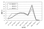
複合粒子A~Cの粉末をふるい分けして、粒度分布を測定した。ふるい分けは、目開き45μm、100μm、300μm、500μm、710μm、1000μm、2000μm、3350μmの金属製網ふるいを用いて行った。図1に、各複合粒子の粉末の粒度分布を示す。図1に示すように、界面活性剤を使用して造粒した複合粒子A、Bの粉末の粒度分布は、界面活性剤を使用せずに造粒した複合粒子Cの粉末の粒度分布と比較して、粒子径が100μm以下の小粒子の割合が少ないことが確認された。なお、後出の表2には、粒子径が100μm以下の小粒子の含有割合が複合粒子全体の10質量%以下であった場合を○印で示し、10質量%を超えていた場合を△印で示している。
複合粒子A~Cの粉末を目視にて観察し、錆びの有無を確認した。結果、後出の表2にも示すとおり、界面活性剤を使用して造粒した複合粒子A、Bにおいては、錆びの発生は見られなかったのに対して、界面活性剤を使用せずに造粒した複合粒子Cにおいては、錆びの発生が確認された。
[サンプル1]
製造した複合粒子Aを用いて、ウレタン発泡成形体を製造した。まず、ポリエーテルポリオール(住化コベストロウレタン(株)製「S-0248」)100質量部と、鎖延長剤のジエチレングリコール(三菱化学(株)製)2質量部と、発泡剤の水2質量部と、テトラエチレンジアミン系触媒(花王(株)製「カオーライザー(登録商標)No.31」)1.5質量部と、シリコーン系整泡剤(東レ・ダウコーニング(株)製「SZ-1333」)0.5質量部と、を混合して、ポリオール原料を調製した。また、ポリイソシアネート原料として、ジフェニルメタンジイソシアネート(MDI)変性物を準備した。MDI変性物は、ポリエーテルポリオール(同上)と、4,4’-ジフェニルメタンジイソシアネート(東ソー(株)製「ミリオネートMT」)と、をイソシアネート(NCO)含有量が70質量%となるように混合し、窒素パージ下、100℃にて180分間反応させて製造した。次に、ポリオール原料100質量部に、複合粒子A129.7質量部を添加、混合して、プレミックスポリオールを調製した。続いて、プレミックスポリオール100.6gと、ポリイソシアネート原料13.7gと、を混合して、混合原料とした(混合原料製造工程)。
複合粒子Aを複合粒子Bに変更した点以外は、サンプル1の製造方法と同様の方法でサンプル2のウレタン発泡成形体を製造した。
複合粒子Aを複合粒子Cに変更した点以外は、サンプル1の製造方法と同様の方法でサンプル3のウレタン発泡成形体を製造した。
製造した三つのサンプルの成形性および熱伝導性を評価した。成形性については、各サンプルのアスカーC硬度を、高分子計器(株)製の「アスカーゴム硬度計C型」を用いて測定し、界面活性剤を使用せずに造粒した複合粒子Cを有するサンプル3のアスカーC硬度の値を基準にして評価した。すなわち、アスカーC硬度の値が、サンプル3のそれに対して±5以内であれば発泡成形への影響なし(後出の表2中、○印で示す)、それ以外は発泡成形への影響あり(同表中、×印で示す)と評価した。熱伝導性については、各サンプルの熱伝導率を、JIS A1412-2:1999の熱流計法に準拠した英弘精機(株)製「HC-110」を用いて測定し、複合粒子Cを有するサンプル3の熱伝導率の値を基準にして評価した。すなわち、熱伝導率の値が、サンプル3のそれと同じかそれよりも大きければ熱伝導性良好(後出の表2中、○印で示す)、それよりも小さい場合を熱伝導性低下(同表中、×印で示す)と評価した。表2に、成形性および熱伝導性の評価結果を示す。

Claims (11)
- ポリウレタンフォームからなる基材と、該基材中に配向して含有されている複合粒子と、を有し、
該複合粒子は、非磁性体からなり熱伝導率が200W/m・K以上の熱伝導性粒子と、該熱伝導性粒子の表面にバインダーにより接着された磁性粒子と、を有し、カルボン酸型界面活性剤およびコハク酸型界面活性剤から選ばれる一種以上の界面活性剤により表面処理されていることを特徴とするウレタン発泡成形体。 - 前記界面活性剤は、コハク酸型界面活性剤を有する請求項1に記載のウレタン発泡成形体。
- 前記界面活性剤は、水溶性である請求項1に記載のウレタン発泡成形体。
- 前記複合粒子の粒度分布において、粒子径が100μm以下の小粒子の含有割合は、該複合粒子の全体質量を100質量%とした場合の10質量%以下である請求項1に記載のウレタン発泡成形体。
- 前記熱伝導性粒子の平均粒子径は、200μm以上2000μm以下である請求項1に記載のウレタン発泡成形体。
- 前記磁性粒子は、鉄粒子を有する請求項1に記載のウレタン発泡成形体。
- 前記複合粒子は、前記熱伝導性粒子の表面にバインダーにより接着された絶縁性無機粒子を有する請求項1に記載のウレタン発泡成形体。
- 前記熱伝導性粒子の平均粒子径は、200μm以上2000μm以下であり、
前記磁性粒子は、鉄粒子を有し、
前記複合粒子は、該熱伝導性粒子の表面にバインダーにより接着された絶縁性無機粒子を有し、
該複合粒子の粒度分布において、粒子径が100μm以下の小粒子の含有割合は、該複合粒子の全体質量を100質量%とした場合の10質量%以下であり、
前記界面活性剤は、コハク酸型界面活性剤を有し水溶性である請求項1に記載のウレタン発泡成形体。 - 請求項1に記載のウレタン発泡成形体の製造方法であって、
非磁性体からなり熱伝導率が200W/m・K以上の熱伝導性粒子の粉末、磁性粒子の粉末、バインダー、カルボン酸型界面活性剤およびコハク酸型界面活性剤から選ばれる一種以上の界面活性剤、および水を有する造粒原料を撹拌して複合粒子を製造する複合粒子製造工程と、
該複合粒子の粉末と、発泡ウレタン樹脂原料と、を混合して混合原料を製造する混合原料製造工程と、
該混合原料を発泡型のキャビティ内に注入し、該キャビティ内の磁束密度が略均一になるように磁場をかけながら発泡成形する発泡成形工程と、
を有することを特徴とするウレタン発泡成形体の製造方法。 - 請求項7に記載のウレタン発泡成形体の製造方法であって、
複合粒子を製造する複合粒子製造工程と、
該複合粒子の粉末と、発泡ウレタン樹脂原料と、を混合して混合原料を製造する混合原料製造工程と、
該混合原料を発泡型のキャビティ内に注入し、該キャビティ内の磁束密度が略均一になるように磁場をかけながら発泡成形する発泡成形工程と、
を有し、
該複合粒子製造工程は、
非磁性体からなり熱伝導率が200W/m・K以上の熱伝導性粒子の粉末、磁性粒子の粉末、バインダー、カルボン酸型界面活性剤およびコハク酸型界面活性剤から選ばれる一種以上の界面活性剤、および水を有する第一原料を撹拌する第一撹拌工程と、
該第一原料の撹拌物に、絶縁性無機粒子の粉末を添加して、さらに撹拌する第二撹拌工程と、
を有することを特徴とするウレタン発泡成形体の製造方法。 - 前記複合粒子製造工程における前記界面活性剤の配合量は、前記熱伝導性粒子の粉末100質量部に対して0.1質量部以上30質量部以下である請求項9または請求項10に記載のウレタン発泡成形体の製造方法。
Priority Applications (4)
| Application Number | Priority Date | Filing Date | Title |
|---|---|---|---|
| CN202380013862.5A CN118076468A (zh) | 2022-06-24 | 2023-05-22 | 氨基甲酸酯发泡成形体及其制造方法 |
| DE112023000211.8T DE112023000211B4 (de) | 2022-06-24 | 2023-05-22 | Urethanschaum-Formgegenstand und Verfahren zu dessen Herstellung |
| JP2024528426A JP7681194B2 (ja) | 2022-06-24 | 2023-05-22 | ウレタン発泡成形体およびその製造方法 |
| US18/500,991 US12441035B2 (en) | 2022-06-24 | 2023-11-02 | Urethane foam-molded article and method for producing same |
Applications Claiming Priority (2)
| Application Number | Priority Date | Filing Date | Title |
|---|---|---|---|
| JP2022101935 | 2022-06-24 | ||
| JP2022-101935 | 2022-06-24 |
Related Child Applications (1)
| Application Number | Title | Priority Date | Filing Date |
|---|---|---|---|
| US18/500,991 Continuation US12441035B2 (en) | 2022-06-24 | 2023-11-02 | Urethane foam-molded article and method for producing same |
Publications (1)
| Publication Number | Publication Date |
|---|---|
| WO2023248671A1 true WO2023248671A1 (ja) | 2023-12-28 |
Family
ID=89379832
Family Applications (1)
| Application Number | Title | Priority Date | Filing Date |
|---|---|---|---|
| PCT/JP2023/018945 Ceased WO2023248671A1 (ja) | 2022-06-24 | 2023-05-22 | ウレタン発泡成形体およびその製造方法 |
Country Status (5)
| Country | Link |
|---|---|
| US (1) | US12441035B2 (ja) |
| JP (1) | JP7681194B2 (ja) |
| CN (1) | CN118076468A (ja) |
| DE (1) | DE112023000211B4 (ja) |
| WO (1) | WO2023248671A1 (ja) |
Cited By (1)
| Publication number | Priority date | Publication date | Assignee | Title |
|---|---|---|---|---|
| WO2024202354A1 (ja) * | 2023-03-31 | 2024-10-03 | 住友理工株式会社 | ウレタン発泡成形体 |
Citations (6)
| Publication number | Priority date | Publication date | Assignee | Title |
|---|---|---|---|---|
| JPH0840724A (ja) * | 1994-08-02 | 1996-02-13 | Toda Kogyo Corp | 球状複合体粒子粉末及びその製造方法 |
| JP2002124318A (ja) * | 2000-10-12 | 2002-04-26 | Jsr Corp | 複合シートおよびその製造方法 |
| JP2011225833A (ja) * | 2010-03-30 | 2011-11-10 | Tokai Rubber Ind Ltd | ウレタン発泡成形体およびその製造方法 |
| JP2015030735A (ja) * | 2013-07-31 | 2015-02-16 | 住友理工株式会社 | エラストマー成形体およびその製造方法 |
| CN106220821A (zh) * | 2016-08-23 | 2016-12-14 | 中国科学院合肥物质科学研究院 | 一种多功能轻质纳米复合泡沫及其制备方法和应用 |
| JP2022145088A (ja) * | 2021-03-19 | 2022-10-03 | 株式会社豊田中央研究所 | 熱伝導材およびその製造方法 |
-
2023
- 2023-05-22 WO PCT/JP2023/018945 patent/WO2023248671A1/ja not_active Ceased
- 2023-05-22 JP JP2024528426A patent/JP7681194B2/ja active Active
- 2023-05-22 CN CN202380013862.5A patent/CN118076468A/zh active Pending
- 2023-05-22 DE DE112023000211.8T patent/DE112023000211B4/de active Active
- 2023-11-02 US US18/500,991 patent/US12441035B2/en active Active
Patent Citations (6)
| Publication number | Priority date | Publication date | Assignee | Title |
|---|---|---|---|---|
| JPH0840724A (ja) * | 1994-08-02 | 1996-02-13 | Toda Kogyo Corp | 球状複合体粒子粉末及びその製造方法 |
| JP2002124318A (ja) * | 2000-10-12 | 2002-04-26 | Jsr Corp | 複合シートおよびその製造方法 |
| JP2011225833A (ja) * | 2010-03-30 | 2011-11-10 | Tokai Rubber Ind Ltd | ウレタン発泡成形体およびその製造方法 |
| JP2015030735A (ja) * | 2013-07-31 | 2015-02-16 | 住友理工株式会社 | エラストマー成形体およびその製造方法 |
| CN106220821A (zh) * | 2016-08-23 | 2016-12-14 | 中国科学院合肥物质科学研究院 | 一种多功能轻质纳米复合泡沫及其制备方法和应用 |
| JP2022145088A (ja) * | 2021-03-19 | 2022-10-03 | 株式会社豊田中央研究所 | 熱伝導材およびその製造方法 |
Cited By (1)
| Publication number | Priority date | Publication date | Assignee | Title |
|---|---|---|---|---|
| WO2024202354A1 (ja) * | 2023-03-31 | 2024-10-03 | 住友理工株式会社 | ウレタン発泡成形体 |
Also Published As
| Publication number | Publication date |
|---|---|
| JP7681194B2 (ja) | 2025-05-21 |
| US20240058996A1 (en) | 2024-02-22 |
| DE112023000211B4 (de) | 2026-04-30 |
| JPWO2023248671A1 (ja) | 2023-12-28 |
| CN118076468A (zh) | 2024-05-24 |
| US12441035B2 (en) | 2025-10-14 |
| DE112023000211T5 (de) | 2024-08-01 |
Similar Documents
| Publication | Publication Date | Title |
|---|---|---|
| CN103476817B (zh) | 聚氨酯发泡成型体及其制造方法 | |
| JP5766477B2 (ja) | ウレタン発泡成形体およびその製造方法 | |
| WO2011122441A1 (ja) | ウレタン発泡成形体およびその製造方法 | |
| JP5108472B2 (ja) | ウレタン発泡成形体、その製造方法、および磁気誘導発泡成形装置 | |
| JP5719887B2 (ja) | エラストマー成形体およびその製造方法 | |
| JP5662743B2 (ja) | ウレタン発泡成形体およびその製造方法 | |
| JP5026892B2 (ja) | ウレタン発泡成形体およびその製造方法 | |
| WO2023248671A1 (ja) | ウレタン発泡成形体およびその製造方法 | |
| JP5577065B2 (ja) | ウレタン発泡成形体およびその製造方法 | |
| JP2012153079A (ja) | ウレタン発泡成形体およびその製造方法 | |
| JP5097092B2 (ja) | ウレタン発泡成形体およびその製造方法 | |
| JP2024144866A (ja) | ウレタン発泡成形体 | |
| JP2025006977A (ja) | ウレタン発泡成形体 | |
| JP2025006980A (ja) | ウレタン発泡成形体 | |
| JP2025086109A (ja) | ウレタン発泡成形体 | |
| JP5551011B2 (ja) | ウレタン発泡成形体の製造方法 | |
| JP5118988B2 (ja) | ウレタン発泡成形体およびその製造方法 | |
| WO2025033343A1 (ja) | ウレタン発泡成形体およびそれを用いた放熱構造体 | |
| JP2010069742A (ja) | ウレタン発泡成形体およびその製造方法 |
Legal Events
| Date | Code | Title | Description |
|---|---|---|---|
| 121 | Ep: the epo has been informed by wipo that ep was designated in this application |
Ref document number: 23826859 Country of ref document: EP Kind code of ref document: A1 |
|
| WWE | Wipo information: entry into national phase |
Ref document number: 202380013862.5 Country of ref document: CN |
|
| WWE | Wipo information: entry into national phase |
Ref document number: 112023000211 Country of ref document: DE |
|
| ENP | Entry into the national phase |
Ref document number: 2024528426 Country of ref document: JP Kind code of ref document: A |
|
| 122 | Ep: pct application non-entry in european phase |
Ref document number: 23826859 Country of ref document: EP Kind code of ref document: A1 |