WO2023248385A1 - 回転子コア、回転子、および電動機 - Google Patents
回転子コア、回転子、および電動機 Download PDFInfo
- Publication number
- WO2023248385A1 WO2023248385A1 PCT/JP2022/024927 JP2022024927W WO2023248385A1 WO 2023248385 A1 WO2023248385 A1 WO 2023248385A1 JP 2022024927 W JP2022024927 W JP 2022024927W WO 2023248385 A1 WO2023248385 A1 WO 2023248385A1
- Authority
- WO
- WIPO (PCT)
- Prior art keywords
- rotor core
- rotor
- magnet
- pairs
- isosceles triangle
- Prior art date
- Legal status (The legal status is an assumption and is not a legal conclusion. Google has not performed a legal analysis and makes no representation as to the accuracy of the status listed.)
- Ceased
Links
Images




Classifications
-
- H—ELECTRICITY
- H02—GENERATION; CONVERSION OR DISTRIBUTION OF ELECTRIC POWER
- H02K—DYNAMO-ELECTRIC MACHINES
- H02K1/00—Details of the magnetic circuit
- H02K1/06—Details of the magnetic circuit characterised by the shape, form or construction
- H02K1/22—Rotating parts of the magnetic circuit
- H02K1/27—Rotor cores with permanent magnets
- H02K1/2706—Inner rotors
- H02K1/272—Inner rotors the magnetisation axis of the magnets being perpendicular to the rotor axis
- H02K1/274—Inner rotors the magnetisation axis of the magnets being perpendicular to the rotor axis the rotor consisting of two or more circumferentially positioned magnets
- H02K1/2753—Inner rotors the magnetisation axis of the magnets being perpendicular to the rotor axis the rotor consisting of two or more circumferentially positioned magnets the rotor consisting of magnets or groups of magnets arranged with alternating polarity
- H02K1/276—Magnets embedded in the magnetic core, e.g. interior permanent magnets [IPM]
- H02K1/2766—Magnets embedded in the magnetic core, e.g. interior permanent magnets [IPM] having a flux concentration effect
-
- H—ELECTRICITY
- H02—GENERATION; CONVERSION OR DISTRIBUTION OF ELECTRIC POWER
- H02K—DYNAMO-ELECTRIC MACHINES
- H02K29/00—Motors or generators having non-mechanical commutating devices, e.g. discharge tubes or semiconductor devices
- H02K29/03—Motors or generators having non-mechanical commutating devices, e.g. discharge tubes or semiconductor devices with a magnetic circuit specially adapted for avoiding torque ripples or self-starting problems
-
- H—ELECTRICITY
- H02—GENERATION; CONVERSION OR DISTRIBUTION OF ELECTRIC POWER
- H02K—DYNAMO-ELECTRIC MACHINES
- H02K2213/00—Specific aspects, not otherwise provided for and not covered by codes H02K2201/00 - H02K2211/00
- H02K2213/03—Machines characterised by numerical values, ranges, mathematical expressions or similar information
Definitions
- Embodiments of the present invention relate to a rotor core, a rotor, and an electric motor.
- a plurality of pairs of magnet slots arranged in a V-shape are formed on the end face of the rotor core of the motor, and a magnet is inserted into each magnet slot.
- holes are formed in the rotor core (for example, see Japanese Patent No. 6987310).
- holes are formed inside each pair of magnet slots arranged in a V-shape, the flow of magnetic flux is inhibited and torque is reduced.
- the rotor core is provided with a plurality of pairs of magnet slots extending in the axial direction of the rotor core, and the plurality of pairs of magnet slots are formed in the rotor core.
- the magnet slots are arranged at equal intervals in the circumferential direction of the rotor core in the radial cross section of the rotor core, and the magnet slots of each pair of the plurality of pairs of magnet slots are arranged in a radius of the rotor core.
- the rotor core is composed of a substantially isosceles triangle whose apex angle is directed toward the center of the rotor core, and a circular arc protruding outward in the radial direction of the rotor core from the base of the isosceles triangle.
- At least a portion of the arc in the hole includes a portion of the first magnet slot located at the outermost side of the rotor core and a part of the second magnet slot located at the outermost side of the rotor core.
- a rotor core is provided that is located radially outward of the rotor core with respect to a first line segment between the rotor core and a portion of the rotor core.
- FIG. 1 is an axial cross-sectional view of an electric motor according to a first embodiment of the present invention.
- FIG. 3 is a radial cross-sectional view of the rotor of the electric motor according to the first embodiment.
- FIG. 3 is a first partially enlarged view of the rotor shown in FIG. 2;
- FIG. 3 is a second partially enlarged view of the rotor shown in FIG. 2;
- FIG. 3 is a third partially enlarged view of the rotor shown in FIG. 2;
- FIG. 2 is a partial cross-sectional view showing the magnetic flux of an electric motor in the prior art.
- FIG. 3 is a diagram showing the relationship between time and torque of an electric motor in the prior art.
- FIG. 3 is a partial cross-sectional view showing the magnetic flux of the electric motor based on the first embodiment.
- FIG. 3 is a diagram showing the relationship between time and torque of the electric motor according to the first embodiment.
- FIG. 3 is a radial cross-sectional view of the rotor core of the electric motor according to the first embodiment.
- FIG. 1 is an axial cross-sectional view of an electric motor according to a first embodiment of the present invention.
- the electric motor 1 includes a stator 9 and a rotor 10 rotatably supported by the stator 9.
- a first bearing 7 and a second bearing 8 are arranged on the inner peripheral surface of the stator 9.
- a shaft portion 5 passing through the rotor 9 is rotatably supported by the stator 9 by a first bearing 7 and a second bearing 8.
- a detector 6 is attached to one end of the stator 9 to detect the rotational speed of the shaft portion 5 and the like.
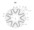
- FIG. 2 is a radial cross-sectional view of the rotor of the electric motor according to the first embodiment.
- the rotor 10 shown in FIG. 2 is approximately ring-shaped with a through hole for the shaft portion 5 in the center. However, as will be described later, it is preferable that the outer peripheral surface of the rotor 10 is not smooth.
- a plurality of pairs of magnet slots 20 extending in the axial direction of the rotor 10 are formed in the rotor 10 at equal intervals in the circumferential direction.
- Each pair of magnet slots 20 includes a first magnet slot 21 tilted counterclockwise with respect to the radius of the rotor 10 and a second magnet slot 22 tilted clockwise with respect to the aforementioned radius of the rotor 10.
- the absolute values of the inclination angles of the first magnet slot 21 and the second magnet slot 22 with respect to the radius are equal to each other.
- the magnet slots 21 and 22 have a substantially rectangular shape corresponding to the shape of the permanent magnets 21a and 21b, and preferably have the same shape. Furthermore, additional cutouts or the like are preferably formed in the magnet slots 21 and 22 for the purpose of easily inserting/removing the permanent magnets 21a and 21b.
- magnet slots 21 and 22 are arranged so as to converge toward each other inward in the radial direction of the rotor 10. In other words, these magnet slots 21 and 22 are formed in a substantially V-shape. However, these magnet slots 21 and 22 do not need to be connected to each other radially inside.
- the outer circumference of the rotor 10 is composed of a plurality of first outer circumferential portions 11 and a plurality of second outer circumferential portions 12 that connect each of the plurality of first outer circumferential portions 11. That is, the plurality of first outer circumferential portions 11 and the plurality of second outer circumferential portions 12 are alternately arranged in the circumferential direction of the rotor 10.
- the plurality of first outer circumferential portions 11 correspond to respective regions of the plurality of pairs of magnet slots 20.
- the plurality of second outer circumferential portions 12 each correspond to a region between two mutually adjacent pairs of magnet slots 20 among the plurality of pairs of magnet slots 20.
- the outermost portion of the first outer circumferential portion 11 is located further outward in the radial direction of the rotor 10 than the outermost portion of the second outer circumferential portion 12 .
- the plurality of first outer peripheral portions 11 as convex portions and the plurality of second outer peripheral portions 12 as recessed portions are arranged alternately in the circumferential direction of the rotor 10.
- the entire first outer circumferential portion 11 is located inside a circle (indicated by a broken line in FIG. 8 described later) whose radius is a line segment connecting the center O of the rotor 10 and the outermost portion of the first outer circumferential portion 11. positioned.
- the outermost portion of the second outer peripheral portion 12 rotates more than one pair of permanent magnets 21b and the other pair of permanent magnets 21a of the two pairs of magnet slots 20 adjacent to the second outer peripheral portion 12. Preferably, it is located radially outward of the child 10.
- the controllability of the electric motor 1 including the rotor 10 can be improved.
- each of the outermost portions of the first outer circumferential portion 11 is composed of at least one curved line.
- Each of the outermost portions of the second outer peripheral portion 12 is composed of at least one straight line.
- the outermost portion of the second outer circumferential portion 12 is connected to one side of the permanent magnets 21 a of one pair of the two pairs of magnet slots 20 adjacent to the second outer circumferential portion 12 , and the other side includes a straight line that is approximately parallel to one side of the pair of permanent magnets 21b.
- the outermost portion of the first outer circumferential portion 11 may be configured with at least one straight line
- the outermost portion of the second outer circumferential portion 12 may be configured with at least one curved line.
- both the outermost portion of the first outer circumferential portion 11 and the outermost portion of the second outer circumferential portion 12 may be configured with at least one straight line
- the outermost portion of the first outer circumferential portion 11 Both the portion and the outermost portion of the second outer circumferential portion 12 may consist of at least one curve.
- at least one of the outermost portion of the first outer circumferential portion 11 and the outermost portion of the second outer circumferential portion 12 may be configured with at least one straight line and at least one curved line.
- the outermost portion of the plurality of first outer circumferential portions 11 is located radially outward of the rotor 10 than the outermost portion of the plurality of second outer circumferential portions 12, so that The outer circumference becomes a shape different from a perfect circle. Therefore, it can be seen that the same effect as described above can be obtained.
- the first outer circumferential portion 11 may be located radially inward of the rotor 10 than the second outer circumferential portion 12. Even in such a case, effects similar to those described above can be obtained and are included in the scope of the first embodiment.
- FIG. 2 a plurality of holes 30 extending in the axial direction of the rotor 10 are formed at equal intervals in the circumferential direction on the end surface of the rotor 10.
- 3 is a first partially enlarged view of the rotor shown in FIG. 2.
- FIG. 2 and 3 each of the plurality of holes 30 is formed in a region of the rotor 10 corresponding to the first outer peripheral portion 11. Strictly speaking, the hole 30 is formed between the first magnet slot 21 and the second magnet slot 22 of the pair of magnet slots 20. The shape of the hole 30 will be described later.
- a plurality of pairs of holes 41 and 42 extending in the axial direction of the rotor 10 are formed at equal intervals in the circumferential direction on the end face of the rotor 10.
- each of the plurality of sets of holes 41, 42 is formed in a region of the rotor 10 corresponding to the second outer circumferential portion 12.
- the hole 41 is formed on the outer side of the rotor 10 in the radial direction than the hole 42, and the hole 41 is smaller than the hole 42.
- the hole 41 is circular
- the hole 42 is an oval shape whose width decreases from the inside to the outside in the radial direction of the rotor 10.
- at least one of the holes 41, 42 may be oval or oval.
- each of the holes 30 includes a first portion 31 and a second portion 32 located outside the first portion 31 in the radial direction of the rotor 10.
- the center lines of the first portion 31 and the second portion 32 are located on one radius R of the rotor 10.
- the "radius R" in this specification is a portion of a straight broken line extending from the center O of the rotor 10 and passing through the center line of the hole 30 in FIG. 8 described later.
- the "radius R" is the center O of the rotor 10 and a line segment connecting the center O to the edge of the first outer peripheral portion 11.
- the first portion 31 has the shape of a substantially isosceles triangle T whose apex angle faces the center O of the rotor 10.
- the second portion 32 has a circular arc shape, for example, a semicircular arc, which projects outward in the radial direction of the rotor 10 from the base of the isosceles triangle T.
- the first part 31 and the second part 32 are smoothly connected to each other.
- the reason for the term “substantially isosceles triangle” is that when the apex of the isosceles triangle T is rounded, when each of the two hypotenuses 33 of the isosceles triangle T is composed of a plurality of straight lines, This is to include cases different from a perfect isosceles triangle, such as a case where each of the two hypotenuses 33 of the isosceles triangle T includes a curve.
- the arc serving as the second portion 32 may be longer or shorter than the semicircular arc.
- the arc serving as the second portion 32 may be an elliptical arc.
- a part of the first magnet slot 21 located at the outermost side of the rotor 10 is designated as "X"
- a part of the first magnet slot 21 located at the outermost side of the rotor 10 A part of is designated as "X'”.
- At least a portion of the arc serving as the second portion 32, for example, point A, is located on the outer side of the rotor 10 in the radial direction than the straight line XX'.
- the length of the hole 30 on the radius R is equal to the length of the permanent magnet facing the hole 30. It is longer than the length of one surface of 21a and 21b (corresponding to the width of the permanent magnet). Therefore, in the first embodiment, the large hole 30 can be formed, and as a result, the weight of the rotor 10 can be reduced, and the speed of the electric motor 1 can be increased. Further, since the second portion 32 is an arc, the flow of magnetic flux is not inhibited when the electric motor 1 having the rotor 10 is driven.
- the first outer circumferential portion 11 in which the hole 30 is formed protrudes more outward in the radial direction of the rotor 10 than the second outer circumferential portion 12.
- the hole 30 can be formed longer in the radial direction of the rotor 10 only in the protruding portion of the first outer peripheral portion 11. Therefore, it will be understood that the hole 30 can be made larger and the rotor 10 can be made lighter.
- FIG. 4 is a second partially enlarged view of the rotor shown in FIG. 2.
- each oblique side 33 of the first portion 31 of the hole 30 has a first straight portion 33a extending from the base of the approximately isosceles triangle T, and an apex angle of the approximately isosceles triangle T from the distal end of the first straight portion 33a. It has a second straight portion 33b extending toward point B of .
- the first straight portion 33a is connected to the second portion 32. Further, the intersection B between the two second straight portions 33b may be rounded.
- the first straight portion 33a and the second straight portion 33b intersect at an intersection C.
- the intersection C is located on the outside of the substantially isosceles triangle T with respect to the hypotenuse corresponding to the intersection C.
- the angle between the radius R and the first straight section 33a shown in FIG. 4 is smaller than the angle between the radius R and the second straight section 33b.
- the first part 31 with the shape described above is larger than the first part 31 as a perfect isosceles triangle T. Therefore, the hole 30 becomes larger and the weight of the rotor 10 can be reduced accordingly. Furthermore, the second straight portion 33b extends from the vicinity of point B so that the hole 30 becomes larger, whereas the first straight portion 33a extends so as to suppress the hole 30 from becoming larger.
- the holes 30 are preferably formed to be larger on the radially inner side of the rotor 10 and smaller on the radially outer side of the rotor 10. This prevents the hole 30 from becoming extremely large and prevents the flow of magnetic flux outside the rotor 10 in the radial direction from being inhibited.
- a part of the first magnet slot 21 closest to the radius R is designated as "Y"
- a part of the second magnet slot 22 closest to the same radius R is designated as "Y". '''.
- the apex B on the apex side of the substantially isosceles triangle T is located near the straight line YY'.
- the vertex B may be located at the intersection of the straight line YY' and the radius R, or may be located inside the rotor 10 in the radial direction from the straight line YY'. In this way, since the end of the hole 30 located inside the rotor 10 in the radial direction is located near the straight line YY', the hole 30 is enlarged, and as a result, the rotor 10 can be made lighter.
- the vertex B is located on the outer side of the rotor 10 in the radial direction than the straight line YY'. Thereby, the strength of the rotor 10 can be ensured.
- the rotor 10 is formed by laminating a plurality of magnetic plates in the axial direction of the rotor 10, the above configuration is particularly preferable because the strength of the plurality of magnetic plates can be ensured.
- FIG. 5 is a third partially enlarged view of the rotor shown in FIG. 2.
- the maximum width L2 of the hole 30 perpendicular to the radius R (see FIGS. 3 and 4) roughly corresponds to the base of the substantially isosceles triangle T described above.
- the maximum width L2 is preferably 1/3 or less of the length L1 of the straight line XX'. This prevents the hole 30 from becoming extremely large and prevents the flow of magnetic flux outside the rotor 10 in the radial direction from being inhibited.
- the line segment L3 shown in FIG. 5 is the length between the edge 5a of the through hole of the rotor 10 into which the shaft portion 5 is inserted and the outermost part of the rotor 10, and is The length of a portion on radius R is shown.
- the line segment L4 indicates the length between the outermost portion of the hole 30 in the radial direction of the rotor 10 and the outermost portion of the rotor 10 in the radial direction. In other words, the line segment L4 is the shortest distance between the first outer peripheral portion 11 and the second portion 32 of the hole 30.
- the length of line segment L3 is preferably shorter than 10 times the length of line segment L4. In one example, the length of line segment L3 is ten times the length of line segment L4. In such a case, it is possible to keep the hole 30 large while preventing the flow of magnetic flux outside the rotor 10 in the radial direction from being inhibited.
- FIG. 6A is a partial sectional view showing the magnetic flux of the electric motor in the prior art
- FIG. 7A is a partial sectional view showing the magnetic flux of the electric motor based on the first embodiment.
- the electric motor 1' shown in FIG. 6A includes a stator 9' and a rotor 10'.
- the electric motor 1 shown in FIG. 7A includes a stator 9 and the rotor 10 described above.
- the structure of the rotors 10, 10' is well known, so a description thereof will be omitted.
- FIGS. 6A and 7A even when holes 30, 41, and 42 are formed as in the electric motor 1, the flow of magnetic flux is not obstructed by the holes 30 etc. .
- the electric motor 1 is lighter than the electric motor 1' due to the holes 30, 41, and 42 formed therein.
- FIG. 6B is a diagram showing the relationship between time and torque of the electric motor in the conventional technology
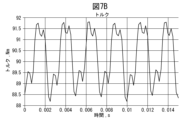
- FIG. 7B is a diagram showing the relationship between time and torque of the electric motor based on the first embodiment.
- the horizontal axis shows time
- the vertical axis shows the torque of the electric motors 1, 1'.
- the maximum value of the torque of the electric motor 1' is between 100 Nm and 101 Nm.
- the maximum value of the torque of the electric motor 1 is between 91.5 Nm and 92 Nm. In other words, even when the holes 30, 41, and 42 are formed, the decrease in torque is suppressed to less than 10%.
- the weight of the rotor 10 can be reduced by forming the holes 30, etc., and the inertia can be reduced without significantly reducing the torque. becomes.
- FIG. 8 is a radial cross-sectional view of the rotor core of the electric motor based on the first embodiment.
- the rotor core 10a of the rotor 10 shown in FIG. 8 is obtained by removing all the permanent magnets 21a, 21b and the rotor 5 from the rotor 10 shown in FIG.
- Other elements shown in FIG. 8 are similar to those described with reference to FIG.
- the rotor core 10a shown in FIG. 8 and the electric motor 1 shown in FIG. 1 etc. are also included in the scope of the first embodiment of the present invention.
Landscapes
- Engineering & Computer Science (AREA)
- Power Engineering (AREA)
- Permanent Field Magnets Of Synchronous Machinery (AREA)
- Iron Core Of Rotating Electric Machines (AREA)
Priority Applications (4)
| Application Number | Priority Date | Filing Date | Title |
|---|---|---|---|
| DE112022007062.5T DE112022007062T5 (de) | 2022-06-22 | 2022-06-22 | Rotorkern, rotor und elektromotor |
| PCT/JP2022/024927 WO2023248385A1 (ja) | 2022-06-22 | 2022-06-22 | 回転子コア、回転子、および電動機 |
| JP2024528175A JP7832325B2 (ja) | 2022-06-22 | 2022-06-22 | 回転子コア、回転子、および電動機 |
| CN202280097048.1A CN119404415A (zh) | 2022-06-22 | 2022-06-22 | 转子铁芯、转子以及电动机 |
Applications Claiming Priority (1)
| Application Number | Priority Date | Filing Date | Title |
|---|---|---|---|
| PCT/JP2022/024927 WO2023248385A1 (ja) | 2022-06-22 | 2022-06-22 | 回転子コア、回転子、および電動機 |
Publications (1)
| Publication Number | Publication Date |
|---|---|
| WO2023248385A1 true WO2023248385A1 (ja) | 2023-12-28 |
Family
ID=89379268
Family Applications (1)
| Application Number | Title | Priority Date | Filing Date |
|---|---|---|---|
| PCT/JP2022/024927 Ceased WO2023248385A1 (ja) | 2022-06-22 | 2022-06-22 | 回転子コア、回転子、および電動機 |
Country Status (4)
| Country | Link |
|---|---|
| JP (1) | JP7832325B2 (https=) |
| CN (1) | CN119404415A (https=) |
| DE (1) | DE112022007062T5 (https=) |
| WO (1) | WO2023248385A1 (https=) |
Citations (5)
| Publication number | Priority date | Publication date | Assignee | Title |
|---|---|---|---|---|
| JP2012205355A (ja) * | 2011-03-24 | 2012-10-22 | Toshiba Corp | モータ |
| JP2013183574A (ja) * | 2012-03-02 | 2013-09-12 | Aichi Elec Co | 回転子および電動機 |
| JP2013188023A (ja) * | 2012-03-08 | 2013-09-19 | Nissan Motor Co Ltd | 永久磁石式電動機のロータ |
| JP2014093860A (ja) * | 2012-11-02 | 2014-05-19 | Denso Corp | 回転電機のロータ |
| WO2020110191A1 (ja) * | 2018-11-27 | 2020-06-04 | 三菱電機株式会社 | 回転電機 |
Family Cites Families (2)
| Publication number | Priority date | Publication date | Assignee | Title |
|---|---|---|---|---|
| JP2000287395A (ja) | 1999-03-30 | 2000-10-13 | Toshiba Corp | 永久磁石式リラクタンス型回転電機の回転子 |
| WO2023135693A1 (ja) | 2022-01-13 | 2023-07-20 | 株式会社 東芝 | 回転子および回転電機 |
-
2022
- 2022-06-22 JP JP2024528175A patent/JP7832325B2/ja active Active
- 2022-06-22 WO PCT/JP2022/024927 patent/WO2023248385A1/ja not_active Ceased
- 2022-06-22 DE DE112022007062.5T patent/DE112022007062T5/de active Pending
- 2022-06-22 CN CN202280097048.1A patent/CN119404415A/zh active Pending
Patent Citations (5)
| Publication number | Priority date | Publication date | Assignee | Title |
|---|---|---|---|---|
| JP2012205355A (ja) * | 2011-03-24 | 2012-10-22 | Toshiba Corp | モータ |
| JP2013183574A (ja) * | 2012-03-02 | 2013-09-12 | Aichi Elec Co | 回転子および電動機 |
| JP2013188023A (ja) * | 2012-03-08 | 2013-09-19 | Nissan Motor Co Ltd | 永久磁石式電動機のロータ |
| JP2014093860A (ja) * | 2012-11-02 | 2014-05-19 | Denso Corp | 回転電機のロータ |
| WO2020110191A1 (ja) * | 2018-11-27 | 2020-06-04 | 三菱電機株式会社 | 回転電機 |
Also Published As
| Publication number | Publication date |
|---|---|
| JP7832325B2 (ja) | 2026-03-17 |
| JPWO2023248385A1 (https=) | 2023-12-28 |
| DE112022007062T5 (de) | 2025-02-20 |
| CN119404415A (zh) | 2025-02-07 |
Similar Documents
| Publication | Publication Date | Title |
|---|---|---|
| US8487495B2 (en) | Rotor for motor | |
| JP5557713B2 (ja) | ロータ | |
| JP2005033941A (ja) | 永久磁石モータの固定子鉄心及び永久磁石モータ | |
| JP6638135B2 (ja) | 電動機 | |
| JP6601169B2 (ja) | 回転電機 | |
| CN106663972B (zh) | 电动机 | |
| JP5764301B2 (ja) | ブラシレスdcモータ | |
| JP5574178B2 (ja) | 回転電機のロータ | |
| JP4127683B2 (ja) | 磁石埋め込み型ロータ | |
| WO2018159339A1 (ja) | ロータ、当該ロータを含むモータ及び当該モータを含む動力装置 | |
| JP5073692B2 (ja) | 回転電機 | |
| JP6556218B2 (ja) | レゾルバロータ及びこれを備えた回転電機 | |
| JP6390647B2 (ja) | 永久磁石式回転電機 | |
| US10630146B2 (en) | Rotor of vehicle AC generator | |
| WO2023248385A1 (ja) | 回転子コア、回転子、および電動機 | |
| JP5394890B2 (ja) | モータ | |
| JP2018026965A (ja) | 回転子及び永久磁石式回転電機 | |
| JP7059059B2 (ja) | 回転電機のロータ | |
| WO2024034149A1 (ja) | 永久磁石回転子および永久磁石回転電機 | |
| WO2025004214A1 (ja) | 回転子コア、回転子および電動機 | |
| JP2015180188A (ja) | ブラシレスdcモータ | |
| JP7851280B2 (ja) | 回転電機 | |
| US20240055918A1 (en) | Permanent magnet rotor and permanent magnet rotary electric machine | |
| TWI660558B (zh) | 永磁馬達之磁件 | |
| JP7396311B2 (ja) | 回転電機用ロータ |
Legal Events
| Date | Code | Title | Description |
|---|---|---|---|
| 121 | Ep: the epo has been informed by wipo that ep was designated in this application |
Ref document number: 22947946 Country of ref document: EP Kind code of ref document: A1 |
|
| WWE | Wipo information: entry into national phase |
Ref document number: 2024528175 Country of ref document: JP |
|
| WWE | Wipo information: entry into national phase |
Ref document number: 112022007062 Country of ref document: DE Ref document number: 202280097048.1 Country of ref document: CN |
|
| WWP | Wipo information: published in national office |
Ref document number: 202280097048.1 Country of ref document: CN |
|
| WWP | Wipo information: published in national office |
Ref document number: 112022007062 Country of ref document: DE |
|
| 122 | Ep: pct application non-entry in european phase |
Ref document number: 22947946 Country of ref document: EP Kind code of ref document: A1 |