WO2023248286A1 - アノード室の液管理方法、及びめっき装置 - Google Patents
アノード室の液管理方法、及びめっき装置 Download PDFInfo
- Publication number
- WO2023248286A1 WO2023248286A1 PCT/JP2022/024506 JP2022024506W WO2023248286A1 WO 2023248286 A1 WO2023248286 A1 WO 2023248286A1 JP 2022024506 W JP2022024506 W JP 2022024506W WO 2023248286 A1 WO2023248286 A1 WO 2023248286A1
- Authority
- WO
- WIPO (PCT)
- Prior art keywords
- anode
- plating
- anode chamber
- plating solution
- chamber
- Prior art date
- Legal status (The legal status is an assumption and is not a legal conclusion. Google has not performed a legal analysis and makes no representation as to the accuracy of the status listed.)
- Ceased
Links
Images



Classifications
-
- C—CHEMISTRY; METALLURGY
- C25—ELECTROLYTIC OR ELECTROPHORETIC PROCESSES; APPARATUS THEREFOR
- C25D—PROCESSES FOR THE ELECTROLYTIC OR ELECTROPHORETIC PRODUCTION OF COATINGS; ELECTROFORMING; APPARATUS THEREFOR
- C25D21/00—Processes for servicing or operating cells for electrolytic coating
- C25D21/12—Process control or regulation
- C25D21/14—Controlled addition of electrolyte components
-
- C—CHEMISTRY; METALLURGY
- C25—ELECTROLYTIC OR ELECTROPHORETIC PROCESSES; APPARATUS THEREFOR
- C25D—PROCESSES FOR THE ELECTROLYTIC OR ELECTROPHORETIC PRODUCTION OF COATINGS; ELECTROFORMING; APPARATUS THEREFOR
- C25D17/00—Constructional parts, or assemblies thereof, of cells for electrolytic coating
-
- C—CHEMISTRY; METALLURGY
- C25—ELECTROLYTIC OR ELECTROPHORETIC PROCESSES; APPARATUS THEREFOR
- C25D—PROCESSES FOR THE ELECTROLYTIC OR ELECTROPHORETIC PRODUCTION OF COATINGS; ELECTROFORMING; APPARATUS THEREFOR
- C25D17/00—Constructional parts, or assemblies thereof, of cells for electrolytic coating
- C25D17/001—Apparatus specially adapted for electrolytic coating of wafers, e.g. semiconductors or solar cells
-
- C—CHEMISTRY; METALLURGY
- C25—ELECTROLYTIC OR ELECTROPHORETIC PROCESSES; APPARATUS THEREFOR
- C25D—PROCESSES FOR THE ELECTROLYTIC OR ELECTROPHORETIC PRODUCTION OF COATINGS; ELECTROFORMING; APPARATUS THEREFOR
- C25D17/00—Constructional parts, or assemblies thereof, of cells for electrolytic coating
- C25D17/002—Cell separation, e.g. membranes, diaphragms
-
- C—CHEMISTRY; METALLURGY
- C25—ELECTROLYTIC OR ELECTROPHORETIC PROCESSES; APPARATUS THEREFOR
- C25D—PROCESSES FOR THE ELECTROLYTIC OR ELECTROPHORETIC PRODUCTION OF COATINGS; ELECTROFORMING; APPARATUS THEREFOR
- C25D17/00—Constructional parts, or assemblies thereof, of cells for electrolytic coating
- C25D17/02—Tanks; Installations therefor
-
- C—CHEMISTRY; METALLURGY
- C25—ELECTROLYTIC OR ELECTROPHORETIC PROCESSES; APPARATUS THEREFOR
- C25D—PROCESSES FOR THE ELECTROLYTIC OR ELECTROPHORETIC PRODUCTION OF COATINGS; ELECTROFORMING; APPARATUS THEREFOR
- C25D21/00—Processes for servicing or operating cells for electrolytic coating
-
- C—CHEMISTRY; METALLURGY
- C25—ELECTROLYTIC OR ELECTROPHORETIC PROCESSES; APPARATUS THEREFOR
- C25D—PROCESSES FOR THE ELECTROLYTIC OR ELECTROPHORETIC PRODUCTION OF COATINGS; ELECTROFORMING; APPARATUS THEREFOR
- C25D21/00—Processes for servicing or operating cells for electrolytic coating
- C25D21/04—Removal of gases or vapours ; Gas or pressure control
-
- C—CHEMISTRY; METALLURGY
- C25—ELECTROLYTIC OR ELECTROPHORETIC PROCESSES; APPARATUS THEREFOR
- C25D—PROCESSES FOR THE ELECTROLYTIC OR ELECTROPHORETIC PRODUCTION OF COATINGS; ELECTROFORMING; APPARATUS THEREFOR
- C25D21/00—Processes for servicing or operating cells for electrolytic coating
- C25D21/12—Process control or regulation
-
- C—CHEMISTRY; METALLURGY
- C25—ELECTROLYTIC OR ELECTROPHORETIC PROCESSES; APPARATUS THEREFOR
- C25D—PROCESSES FOR THE ELECTROLYTIC OR ELECTROPHORETIC PRODUCTION OF COATINGS; ELECTROFORMING; APPARATUS THEREFOR
- C25D21/00—Processes for servicing or operating cells for electrolytic coating
- C25D21/16—Regeneration of process solutions
- C25D21/18—Regeneration of process solutions of electrolytes
-
- C—CHEMISTRY; METALLURGY
- C25—ELECTROLYTIC OR ELECTROPHORETIC PROCESSES; APPARATUS THEREFOR
- C25D—PROCESSES FOR THE ELECTROLYTIC OR ELECTROPHORETIC PRODUCTION OF COATINGS; ELECTROFORMING; APPARATUS THEREFOR
- C25D3/00—Electroplating: Baths therefor
- C25D3/02—Electroplating: Baths therefor from solutions
- C25D3/38—Electroplating: Baths therefor from solutions of copper
-
- C—CHEMISTRY; METALLURGY
- C25—ELECTROLYTIC OR ELECTROPHORETIC PROCESSES; APPARATUS THEREFOR
- C25D—PROCESSES FOR THE ELECTROLYTIC OR ELECTROPHORETIC PRODUCTION OF COATINGS; ELECTROFORMING; APPARATUS THEREFOR
- C25D5/00—Electroplating characterised by the process; Pretreatment or after-treatment of workpieces
- C25D5/08—Electroplating with moving electrolyte e.g. jet electroplating
-
- C—CHEMISTRY; METALLURGY
- C25—ELECTROLYTIC OR ELECTROPHORETIC PROCESSES; APPARATUS THEREFOR
- C25D—PROCESSES FOR THE ELECTROLYTIC OR ELECTROPHORETIC PRODUCTION OF COATINGS; ELECTROFORMING; APPARATUS THEREFOR
- C25D7/00—Electroplating characterised by the article coated
- C25D7/12—Semiconductors
Definitions
- the present invention relates to a liquid management method for an anode chamber, particularly a liquid management method for an anode chamber of a plating apparatus, and a plating apparatus.
- a plating apparatus capable of plating a substrate such as a semiconductor wafer
- a plating apparatus as described in US Patent Application Publication No. 2020-0017989 Patent Document 1
- This plating apparatus includes a plating tank that stores a plating solution and in which an anode is arranged, a substrate holder that holds a substrate as a cathode so as to face the anode, and a space between the anode and the substrate holder.
- the plating tank is provided with a diaphragm disposed in the plating tank that partitions the inside of the plating tank into an anode chamber and a cathode chamber, and allows the plating solution to flow along the surface of the substrate.
- the diaphragm is placed under the frame fixed in the plating bath, but when the pressure in the cathode chamber becomes higher than the pressure in the anode chamber, the diaphragm separates from the frame and extends downward, creating an air bubble between the frame and the diaphragm. may form pockets that trap
- Patent Document 1 the plating solution is supplied to the anode chamber so that the pressure in the anode chamber is higher than the pressure in the cathode chamber. to prevent the diaphragm from stretching downward.
- an anode and a diaphragm in contact with or in close contact with the upper surface of the anode are arranged, and an upper cathode chamber and a lower anode chamber partitioned by the diaphragm are in communication with the anode chamber.
- a liquid management method for an anode chamber which includes the step of supplying pure water or an electrolytic solution to the anode chamber when it is determined that the anode chamber is the same.
- FIG. 1 is a perspective view showing the overall configuration of a plating apparatus according to an embodiment.
- FIG. 1 is a plan view showing the overall configuration of a plating apparatus according to an embodiment.
- FIG. 1 is a cross-sectional view for explaining the configuration of a plating module according to an embodiment.
- FIG. 3 is an enlarged cross-sectional view of a part of the plating module.
- FIG. 3 is an enlarged cross-sectional view of the vicinity of the anode.
- 7 is a cross-sectional view showing an example of a structure for fixing a diaphragm 71 to an anode 41.
- FIG. 7 is a cross-sectional view showing an example of a structure for fixing a diaphragm 71 to an anode 41.
- FIG. 7 is a cross-sectional view showing an example of a structure for fixing a diaphragm 71 to an anode 41.
- FIG. 1 is a perspective view showing the overall configuration of a plating
- a plating apparatus 1000 according to an embodiment of the present invention will be described with reference to the drawings.
- the drawings are schematically illustrated to facilitate understanding of the features of the objects, and the dimensional ratios of each component are not necessarily the same as the actual ones.
- XYZ orthogonal coordinates are shown for reference. Of these orthogonal coordinates, the Z direction corresponds to the upper direction, and the -Z direction corresponds to the lower direction (the direction in which gravity acts).
- FIG. 1 is a perspective view showing the overall configuration of a plating apparatus 1000 of this embodiment.
- FIG. 2 is a plan view showing the overall configuration of the plating apparatus 1000 of this embodiment.
- the plating apparatus 1000 includes a load port 100, a transfer robot 110, an aligner 120, a prewet module 200, a presoak module 300, a plating module 400, a cleaning module 500, a spin rinse dryer 600, a transfer A device 700 and a control module 800 are provided.
- the load port 100 is a module for loading a wafer (substrate) housed in a cassette such as a FOUP (not shown) into the plating apparatus 1000, and for unloading a substrate from the plating apparatus 1000 to a cassette.
- a cassette such as a FOUP (not shown)
- four load ports 100 are arranged side by side in the horizontal direction, but the number and arrangement of the load ports 100 are arbitrary.
- the transfer robot 110 is a robot for transferring a substrate, and is configured to transfer the substrate between the load port 100, the aligner 120, the pre-wet module 200, and the spin rinse dryer 600. When transferring the substrate between the transfer robot 110 and the transfer device 700, the transfer robot 110 and the transfer device 700 can transfer the substrate via a temporary storage table (not shown).
- the aligner 120 is a module for aligning the orientation flat, notch, etc. of the substrate in a predetermined direction.
- two aligners 120 are arranged side by side in the horizontal direction, but the number and arrangement of aligners 120 are arbitrary.
- the pre-wet module 200 wets the surface of the substrate to be plated before plating with a treatment liquid such as pure water or deaerated water, thereby replacing the air inside the pattern formed on the substrate surface with the treatment liquid.
- the pre-wet module 200 is configured to perform a pre-wet process that replaces the processing solution inside the pattern with a plating solution during plating, thereby making it easier to supply the plating solution inside the pattern.
- two pre-wet modules 200 are arranged side by side in the vertical direction, but the number and arrangement of the pre-wet modules 200 are arbitrary.
- the pre-soak module 300 cleans the surface of the plating base by etching away, for example, an oxide film with high electrical resistance on the surface of a seed layer formed on the surface to be plated of a substrate before plating using a treatment solution such as sulfuric acid or hydrochloric acid. Alternatively, it is configured to perform pre-soak processing to activate. In this embodiment, two pre-soak modules 300 are arranged side by side in the vertical direction, but the number and arrangement of the pre-soak modules 300 are arbitrary.
- the plating module 400 performs plating processing on the substrate. In this embodiment, there are two sets of 12 plating modules 400 arranged in parallel, three in the vertical direction and four in the horizontal direction, for a total of 24 plating modules 400. The number and arrangement of are arbitrary.
- the cleaning module 500 is configured to perform a cleaning process on the substrate in order to remove plating solution and the like remaining on the substrate after the plating process.
- two cleaning modules 500 are arranged side by side in the vertical direction, but the number and arrangement of the cleaning modules 500 are arbitrary.
- the spin rinse dryer 600 is a module for drying a substrate after cleaning by rotating it at high speed.
- two spin rinse dryers 600 are arranged side by side in the vertical direction, but the number and arrangement of spin rinse dryers 600 are arbitrary.
- the transport device 700 is a device for transporting substrates between a plurality of modules within the plating apparatus 1000.
- the control module 800 is configured to control a plurality of modules of the plating apparatus 1000, and can be configured, for example, from a general computer or a dedicated computer with an input/output interface with an operator.
- the transport device 700 transports the plated substrate to the cleaning module 500.
- the cleaning module 500 performs cleaning processing on the substrate.
- the transport device 700 transports the substrate that has been subjected to the cleaning process to the spin rinse dryer 600.
- the spin rinse dryer 600 performs a drying process on the substrate.
- the transfer robot 110 receives the substrate from the spin rinse dryer 600 and transfers the dried substrate to the cassette of the load port 100. Finally, the cassette containing the substrates is carried out from the load port 100.
- the configuration of the plating apparatus 1000 described in FIGS. 1 and 2 is only an example, and the configuration of the plating apparatus 1000 is not limited to the configuration in FIGS. 1 and 2.
- the control module 800 includes, for example, a CPU, volatile memory, and/or nonvolatile memory.
- Memory is also referred to as a storage medium or recording medium.
- the memory stores various programs, various parameters, and the like.
- the CPU reads various programs, various parameters, etc., and executes the various programs.
- plating module 400 Next, the plating module 400 will be explained. Note that since the plurality of plating modules 400 included in the plating apparatus 1000 according to this embodiment have the same configuration, one plating module 400 will be explained.
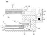
- FIG. 3 is a cross-sectional view for explaining the configuration of a plating module according to one embodiment.
- FIG. 4 is an enlarged cross-sectional view of a part of the plating module.
- the plating apparatus 1000 is a so-called face-down type or cup type plating apparatus in which the surface of the substrate to be plated faces downward and is brought into contact with the plating solution.
- the plating module 400 of the plating apparatus 1000 according to the present embodiment mainly includes a plating tank 10, an anode 41 disposed in the plating tank 10, and a substrate Wf as a cathode so as to be disposed facing the anode 41.
- the plating module 400 can include a rotating mechanism, a tilting mechanism, and/or a lifting mechanism (not shown) that rotates, tilts, and/or raises and lowers the substrate holder 31.
- the plating tank 10 can include an inner tank 10a including a cathode chamber Cc and an anode chamber Ca, and an outer tank 10b as an overflow tank (overflow chamber) 20.
- the plating tank 10 (inner tank 10a) is partitioned by a diaphragm 71 into an upper cathode chamber Cc and a lower anode chamber Ca.
- the plating solution (anolyte) Ps in the anode chamber Ca and the plating solution (cathode solution) Ps in the cathode chamber Cc are supplied from the same source and have the same composition.
- the plating tank 10 is provided with an exhaust passage 11 that communicates with the anode chamber Ca and is open to the atmosphere.
- the exhaust passage 11 exhausts air bubbles 61 in the anolyte in the anode chamber Ca.
- at least a portion of the exhaust passage 11 extends in the vertical direction outside the overflow tank 20 (outer tank 10b) and opens to the atmosphere at the exit of the exhaust passage.
- the anode 41 is arranged at the bottom inside the plating tank 10.
- the specific type of anode 41 is not particularly limited, and a soluble anode or an insoluble anode can be used.
- an insoluble anode is used as the anode 41.
- the specific type of this insoluble anode is not particularly limited, and platinum, titanium, iridium oxide, etc. (for example, IrO2/Ti, Pt/Ti) can be used.
- the surface of the anode 41 may further have a top coat layer for the purpose of suppressing decomposition of additives in the plating solution.
- an anode mask 43 is provided on the upper surface side (substrate Wf side) of the anode 41.
- the anode mask 43 is an electric field adjustment member that has an opening that exposes the anode 41 and adjusts the electric field directed from the anode 41 toward the substrate Wf by adjusting the range in which the anode 41 is exposed by the opening.
- the anode mask 43 may be an anode mask having a predetermined opening size or a variable anode mask in which the opening size can be changed.
- the anode mask 43 may include a plurality of blades, and the size of the opening may be adjusted by a mechanism similar to a camera aperture.
- the anode mask 43 may be omitted in some cases.
- a paddle (not shown) may be placed inside the plating tank 10 near the substrate Wf (in this embodiment, between the resistor 51 and the substrate Wf).
- the paddle reciprocates in a direction generally parallel to the surface to be plated of the substrate Wf to generate a strong flow of plating solution on the surface of the substrate Wf.
- the ions in the plating solution near the surface of the substrate Wf can be made uniform, and the in-plane uniformity of the plating film formed on the surface of the substrate Wf can be improved.
- the shape and size of the through-hole are not particularly limited either, but from the viewpoint of ease of processing and stability of voltage during plating, the size of the opening (diameter if circular, length of one side if square) , preferably about 1 mm to 5 mm.
- the anode 41 is supported within the plating tank 10 by an anode holder 42, also called an anode holder.
- a diaphragm 71 (Nafion® ), porous membranes, etc.) are joined or closely adhered.
- the diaphragm 71 separates the inside of the inner tank 10a of the plating tank 10 into an anode chamber Ca and a cathode chamber Cc.
- the diaphragm 71 is a membrane that allows cations (eg, hydrogen ions H+) in the plating solution to pass therethrough, but does not allow bubbles (eg, oxygen gas) and additives in the plating solution to pass through.
- Diaphragm 71 can be, for example, a neutral membrane, an ion exchange membrane, or a combination thereof.
- the diaphragm 71 may be formed by stacking a plurality of membranes or layers.
- the configuration of the diaphragm 71 is one example, and other configurations may be adopted.
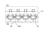
- FIG. 5 is an enlarged cross-sectional view of the vicinity of the anode 41. Since the anode 41 has a large number of through holes 41A, the surface of the anode 41 is always kept moist with the plating solution supplied from the through holes 41A even during electrode reaction.
- the diaphragm 71 is an ion-permeable membrane that can be penetrated and wetted by the plating solution, so as shown in the figure, the anode 41 has an ion permeability that allows the plating solution to permeate and wet the anode 41 on the substrate side surface (at or near the area where the diaphragm 71 is in close contact with the anode 41).
- the bubbles 61 that have moved to the back side of the anode 41 are discharged to the outside of the plating tank 10 through the exhaust passage 11 (FIGS. 3 and 4) provided outside the diaphragm 71.
- the ion conduction path between the anode and the cathode is stably ensured, and the accumulation of air bubbles 61 on the ion conduction path between the anode and the cathode is prevented from adversely affecting the ion conduction. can be avoided.
- the influence of bubbles generated at the anode can be suppressed, plating on the substrate can be performed stably, and the uniformity of the plating film thickness can be improved.
- FIGS. 3 and 4 correspond to an example in which the holding plate 72 (FIG. 6) is employed.
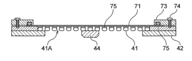
- the diaphragm 71 is pressed against the substrate-side surface of the anode 41 by a pressing plate 72 having a large number of through holes 72A, and is fixed in close contact with the upper surface of the anode 41.
- the press plate 72 is fixed to the anode holder 42 with a fastening member 74 such as a screw so as to press the anode 41 and the diaphragm 71 from above.
- the diaphragm 71 is held between the holding plate 72 and the anode 41, and the diaphragm 71 is brought into close contact with the anode 41.
- a sealing member 75 (for example, an O-ring) is provided between the presser plate 72 and the diaphragm 71 to seal the space between them.
- the anode holder 42 and the holding plate 72 are preferably made of a material that is not corroded by the plating solution, and can be made of, for example, a resin such as vinyl chloride, or a metal such as Pt or Ti.
- the diaphragm 71 is bonded and fixed to the substrate side surface of the anode 41.
- the bonding layer 75 that bonds the diaphragm 71 to the anode 41 preferably has ion permeability.
- it can be a resin having an ion exchange group, or a porous bonding layer containing a resin and a filler, and in one example, it can be a perfluorocarbon material having a sulfonic acid group.
- the outer peripheral portion of the diaphragm 71 is pressed and fixed against the anode holder 42 by a presser ring 73.
- a sealing member 75 (for example, an O-ring) is provided between the presser ring 73 and the diaphragm 71 to seal the space between them.
- the anode holder 42 and the holding ring 73 are preferably made of a material that is not corroded by the plating solution, and can be made of, for example, a resin such as vinyl chloride, or a metal such as Pt or Ti.
- a bubble regulating plate (back plate) 140 is provided below the anode 41 in the anode chamber Ca so as to face the lower surface of the anode 41.
- a gap is provided between the bubble regulating plate 140 and the anode 41 by a spacer or the like.
- the space between the bubble regulating plate 140 and the anode 41 and the space outside the anode chamber are configured to communicate at one or more locations.
- the bubble regulating plate 140 limits the thickness of the bubbles (see FIG. 5) accumulated on the lower surface of the anode 41 to within the distance between the anode 41 and the bubble regulating plate 140, thereby reducing the thickness of the bubbles on the lower surface of the anode 41.
- changes in the pressure of the plating solution near the lower surface of the anode 41 can be suppressed, and fluctuations in the electrode potential at the anode 41 can be suppressed.
- By suppressing fluctuations in the electrode potential of the anode during plating it is possible to suppress deterioration in the uniformity of the plating film thickness.
- a bubble buffer ring (not shown) that surrounds the anode 41 and protrudes downward at a predetermined height from the lower surface of the anode may be arranged.
- air bubbles can accumulate as air bubbles are discharged from the underside of the anode during plating. Changes in amount can be suppressed. Note that it is also possible to have a configuration in which the bubble adjustment plate 140 and the bubble buffer ring are not provided.
- the exhaust passage 11 is provided with an overflow passage 11A communicating with the overflow tank 20, and the lower surface of the overflow passage 11A constitutes an overflow surface OFa of the anode chamber Ca.
- the overflow passage 11A is provided so that the height of the overflow passage 11A (overflow surface OFa) is lower than the overflow surface OFc of the cathode chamber Cc.
- the plating solution in the exhaust passage 11 flows into the overflow tank 20 so that the plating solution level Sa in the exhaust passage 11 (anode chamber Ca) is lower than the overflow passage 11A (overflow surface OFa). It is set to not overflow.
- the settings are made so that they do not overflow into the cathode chamber Cc side, that is, into the overflow tank 20. This prevents the plating solution in the anode chamber Ca, in which the additive has been consumed, from entering the cathode chamber Cc via the overflow tank 20, thereby preventing the plating solution in the cathode chamber Cc from deteriorating.
- the plating solution in the exhaust passage 11 flows through the overflow passage 11A.
- the water overflows into the overflow tank 20 through the tank.
- the overflow surface OFa of the plating solution in the anode chamber Ca is set lower than the overflow surface OFa of the plating solution in the cathode chamber Cc, it is possible to maintain the pressure in the cathode chamber Cc higher than the pressure in the anode chamber Ca. This pressure difference allows the diaphragm 71 to be pressed against the anode 41 and brought into close contact with it.
- a liquid level sensor 12 is arranged in the plating solution in the exhaust passage 11.
- the liquid level sensor 12 detects whether the liquid level Sa of the plating solution in the exhaust passage 11 is above a predetermined height (or less than a predetermined height).
- the liquid level sensor 12 may be an electrode type, a float type (such as a float switch), a capacitance type, an ultrasonic type, a vibration type, or any other liquid level sensor.
- the liquid level sensor 12 outputs an ON signal when the liquid level Sa of the plating solution is above a predetermined height, and outputs an OFF signal when the liquid level Sa of the plating solution is less than a predetermined height. can be taken as a thing.
- the liquid level sensor 12 may, for example, measure the distance to the liquid level.
- the liquid level sensor 12 is connected to the control module 800 by wire or wirelessly, and the control module 800 receives the output of the liquid level sensor 12.
- a concentration sensor (electrical conductivity sensor) 13 is arranged in the plating solution in the exhaust passage 11. Electrical conductivity and electrical conductivity sensors are sometimes referred to as electrical conductivity and conductivity sensors.
- the concentration sensor (electrical conductivity sensor) 13 may be arranged within the anode chamber Ca.
- the concentration sensor (electrical conductivity sensor) 13 is connected to the control module 800 by wire or wirelessly.
- the concentration sensor (electrical conductivity sensor) 13 indicates that either a concentration sensor or an electrical conductivity sensor is provided. However, both the concentration sensor and the electrical conductivity sensor may be provided. Both the concentration sensor and the electrical conductivity sensor 13 may be omitted.
- the cathode chamber Cc and the anode chamber Ca are supplied with plating solution from the reservoir 81.
- the cathode chamber Cc is connected to the reservoir 81 via channels 83 and 82.
- the anode chamber Ca is connected to the reservoir 81 via channels 85, 84, and 82.
- a pump 86 and a filter 87 are arranged in the flow path 82 .
- a valve 88 is arranged in the flow path 83, and a valve 89 is arranged in the flow path 84. When valve 88 is opened, plating solution is supplied from reservoir 81 to cathode chamber Cc. When valve 89 is opened, plating solution is supplied from reservoir 81 to anode chamber 85 .
- the plating solution that overflowed beyond the overflow surface OFc of the cathode chamber Cc is collected in the overflow tank 20 and returned to the reservoir 88 via the flow path 95.
- the reservoir 81, channels 82, 83, overflow tank 20, and channel 95 constitute a circulation path 80 of the cathode chamber Cc. During plating, the plating solution in the cathode chamber Cc is circulated through the circulation path 80.
- the valve 89 is closed, and the plating solution in the anode chamber Ca is not circulated. do not have.
- the same plating solution as that supplied to the cathode chamber is supplied to the anode chamber, and the plating solution overflowing from the cathode chamber and the anode chamber enters the common overflow tank 20 and is stored in the common reservoir. After being returned to 81, it is again supplied to the cathode chamber and the anode chamber.
- the plating solution is supplied to the anode chamber Ca only when the anode chamber Ca is filled, and the plating solution in the anode chamber Ca is not circulated.
- a liquid supply source 91 is connected to the anode chamber Ca via channels 85 and 92, and a valve 93 is arranged in the channel 92.
- liquid source 91 is a source that provides pure water (eg, DIW).
- the valve 93 is opened, pure water is supplied from the liquid supply source 91 to the anode chamber Ca.
- the channels 85 and 92 and the liquid supply source 91 constitute a liquid supply path 90.
- the valve 93 is opened and the liquid supply source 91 is connected to the flow path 92. , 85 to supply pure water to the anode chamber Ca.
- the concentration sensor (electrical conductivity sensor) 13 detects that the concentration (electrical conductivity) of the plating solution in the anode chamber Ca exceeds a predetermined concentration (electrical conductivity)
- the control module 800 Set off an alarm.
- the concentration (electrical conductivity) of the plating solution increases according to the evaporated water, so that the predetermined concentration (electrical conductivity ) corresponds to the liquid level Sa of the plating solution being less than a specific height.
- the predetermined concentration (electrical conductivity) can be set to a value corresponding to a predetermined height H0 of the liquid level Sa of the plating solution.
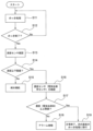
- FIG. 8 shows a flowchart of anode chamber liquid management control. This process is executed by control module 800.
- step S11 a plating process is performed on the substrate Wf.
- step S12 it is determined whether or not the plating process has ended, and if the plating process has not ended, the process returns to step S11 and continues the plating process. If it is determined in step S11 that the plating process has been completed, the process moves to step S13.
- step S13 the output of the liquid level sensor 12 is confirmed.
- step S14 it is determined whether the height of the liquid level Sa of the plating solution in the anode chamber Ca is equal to or higher than the lower limit value (predetermined height) H0, based on the output of the liquid level sensor.
- step S14 if the output of the liquid level sensor 12 indicates that the height of the liquid level Sa of the plating solution in the anode chamber Ca is less than the lower limit H0 (for example, sensor output OFF), the process moves to step S15. do.
- the lower limit H0 for example, sensor output OFF
- step S15 the valve 93 is opened to supply pure water from the liquid supply source 91 to the anode chamber Ca. Replenishment of pure water is performed, for example, based on the output of the liquid level sensor 12, until the height of the liquid level Sa of the plating solution in the anode chamber Ca becomes equal to or higher than the lower limit value H0 (liquid level sensor output ON). If the difference between the height of the liquid level Sa of the plating liquid supplied to the anode chamber Ca in the initial state and the height of the liquid level Sa of the plating liquid at the time when the liquid level sensor 12 is turned OFF is known, the difference corresponds to that difference. Pure water may be supplied to replenish the amount of plating solution.
- step S14 if the output of the liquid level sensor 12 indicates that the height of the liquid level Sa of the plating solution in the anode chamber Ca is equal to or higher than the lower limit value H0 (for example, the liquid level sensor output is ON), the process proceeds to step S16. Transition.
- step S16 the output of the concentration sensor (electrical conductivity sensor) 13 is confirmed.
- step S17 based on the output of the concentration sensor (electrical conductivity sensor) 13, it is determined whether the concentration (electrical conductivity) of the plating solution in the anode chamber Ca is less than or equal to the upper limit value of the concentration (electrical conductivity). .
- step S17 if the output of the concentration sensor (electrical conductivity sensor) 13 indicates that the concentration (electrical conductivity) of the plating solution in the anode chamber exceeds the concentration upper limit value (electrical conductivity upper limit value), Then, the process moves to step S18, and an alarm is issued. If the concentration (electrical conductivity) is outside the normal range in step S17, the liquid level sensor 12 has failed, and the height of the liquid level Sa was determined to be higher than the lower limit value H0 in step S14, but the liquid Since there is a possibility that the height of the surface Sa is less than the lower limit value H0, an alarm is generated in step S18. The user can check whether the liquid level sensor 12 is malfunctioning in response to the alarm.
- an alarm may be issued when either the concentration sensor or the electrical conductivity sensor exceeds the upper limit, or the concentration sensor and the electrical conductivity An alarm may be issued when both of the sensors exceed the upper limit values.
- an alarm is issued when the output of the installed sensor exceeds the upper limit value.
- step S17 if the output of the concentration sensor (electrical conductivity sensor) 13 indicates that the concentration (electrical conductivity) of the plating solution in the anode chamber is less than or equal to the concentration upper limit value (electrical conductivity upper limit value), In step S19, the flow of the anode chamber liquid management control is ended, and the process moves to the plating process for the next substrate (step S11). If there is both a concentration sensor and an electrical conductivity sensor, it may be considered normal if both the concentration sensor and the electrical conductivity sensor are below the upper limit, or if either the concentration sensor or the electrical conductivity sensor is below the upper limit. It may be considered normal if the following conditions are met.
- FIG. 9 is a photograph of an experimental plating module (without diaphragm).
- FIG. 10 is a photograph of an experimental plating module (with diaphragm).
- an anode 41 and a cathode 32 spaced upward from the anode 41 at a predetermined distance are arranged in a plating tank 10 that holds a plating solution (FIGS. 12A and 12B). (see also).
- FIG. 12A and 12B a plating solution
- anode 41 in a plating tank 10 that holds a plating solution, there is an anode 41, a diaphragm 71 that is in close contact with the upper surface of the anode 41, a holding plate 72 that presses down the diaphragm 71, and a holding plate 72 that is spaced upwardly from the holding plate 72 at a predetermined distance.
- the anode 41 is connected to the positive terminal of a power source (not shown), and the cathode 32 is connected to the negative terminal of the power source.
- the cathode 32 is separated from the holding plate 72 by the buoyancy of the plating solution, but the cathode 32 may be placed on a spacer or the like as appropriate to be separated from the holding plate 72.
- Anode IrO2/Ti lath (wire mesh)
- Cathode Pt/Ti lath (wire mesh)
- Diaphragm Yumicron Y-9207TA (micro-porous membrane) (Yuasa Membrane Brain System)
- Electrolyte 100g/L-H2SO4
- Anode area 0.24dm2 (60mm x 40mm)
- FIG. 11 shows the measurement results of the anode voltage during plating. As shown in the measurement results, it was found that even when the diaphragm 71 was used, the voltage of the anode 41 during energization was stable and showed the same voltage change as in the case without the diaphragm. From this result, it is expected that even if the diaphragm 71 is brought into close contact with the anode 41, the voltage between the anode and the cathode will show a normal change and normal plating processing can be performed.
- FIG. 12A is a photograph of the plating module (without diaphragm) before plating.
- FIG. 12B is a photograph of the plating module (without diaphragm) during plating.
- a large amount of bubbles generated at the anode 41 accumulated on both the upper and lower sides of the anode 41. Since a large amount of air bubbles accumulate between the anode 41 and the cathode 32, which serve as an ion conduction path, it is expected that the uniformity of the plating film thickness will be adversely affected.
- FIG. 13A is a photograph of the plating module (with diaphragm) before plating.
- FIG. 13B is a photograph of the plating module (with diaphragm) during plating.
- the air bubbles generated at the anode 41 exist below the anode 41, but the air bubbles accumulate between the anode 41 and the cathode 32, which forms an ion conduction path. It was observed that this was suppressed. Therefore, it is expected that the uniformity of the plating film thickness can be improved.
- the liquid level in the anode chamber is always lower than the liquid level in the cathode chamber, the pressure in the cathode chamber that is higher than the pressure in the anode chamber allows the diaphragm to be pressed against and in close contact with the anode.
- the height of the liquid level in the anode chamber is monitored by the liquid level sensor, and when the height of the liquid level in the anode chamber becomes less than a predetermined height (lower limit value), Since the anode chamber is replenished with pure water, depletion of the plating solution in the anode chamber can be suppressed or prevented.
- the gas generated in the anode can be naturally discharged without circulating the plating solution in the anode chamber, so the structure and/or operation of the plating tank becomes simple.
- cations can be conducted to the substrate side through the diaphragm that is in close contact with the anode, it is possible to reliably secure an ion conduction path between the anode and the substrate while avoiding the influence of air bubbles.
- the electrolytic solution preferably has a lower concentration than the plating solution in the anode chamber and/or the cathode chamber.
- the concentration/electrical conductivity of the plating solution in the anode chamber increases each time the electrolyte is replenished, so the upper limit for evaluating the detection value of the concentration sensor/electrical conductivity sensor The value is set taking into account the concentration of the electrolyte.
- the concentration sensor/electrical conductivity sensor and the control based on these sensors may be omitted.
- a liquid management method for an anode chamber which includes the step of supplying pure water or an electrolytic solution to the anode chamber when it is determined that the anode chamber is the same.
- the electrolyte may have the same composition as the plating solution in the anode and/or cathode compartments, and may have a lower concentration than the plating solution in the anode and/or cathode compartments.
- the electrolytic solution preferably has a lower concentration than the plating solution in the anode chamber and/or the cathode chamber.
- the plating solution in the anode chamber when the liquid level of the plating solution in the anode chamber rises, the plating solution in the anode chamber overflows at a height lower than the height at which the plating solution in the cathode chamber overflows. including.
- the method further includes the step of not circulating the plating solution in the anode chamber but circulating the plating solution in the cathode chamber.
- the consumption of additives can be suppressed by not circulating the plating solution in the anode chamber.
- the same plating solution supply source (reservoir) is used to supply and circulate the plating solution to the cathode chamber and anode chamber, if the plating solution is circulated on the anode side during plating, expensive additives may decompose ( consumption) will continue to be consumed. Consumption of additives can be suppressed by supplying the plating solution to the anode chamber only when the anode chamber is filled and not circulating the plating solution in the anode chamber.
- the method includes the step of introducing plating solutions having the same composition into the anode chamber and the cathode chamber.
- plating solutions having the same composition are introduced into the anode chamber and the cathode chamber from the same plating solution supply source.
- the configuration of the flow path connected to the anode chamber can be further simplified.
- changes in the concentration of the plating solution in the anode chamber can be suppressed or prevented by supplying the amount of pure water that has decreased in the anode chamber. Moreover, the cost of replenishing liquid can be suppressed.
- Patent Document 1 US Patent Application Publication No. 2020-0017989 (Patent Document 1), and the specification, claims, drawings, and abstract of International Patent Application No. PCT/JP2022/016809 filed on March 31, 2022 The entire disclosure of this application is incorporated by reference into this application.
Landscapes
- Chemical & Material Sciences (AREA)
- Engineering & Computer Science (AREA)
- Chemical Kinetics & Catalysis (AREA)
- Electrochemistry (AREA)
- Materials Engineering (AREA)
- Metallurgy (AREA)
- Organic Chemistry (AREA)
- Automation & Control Theory (AREA)
- Life Sciences & Earth Sciences (AREA)
- Sustainable Development (AREA)
- Electroplating Methods And Accessories (AREA)
Abstract
Description
図1は、本実施形態のめっき装置1000の全体構成を示す斜視図である。図2は、本実施形態のめっき装置1000の全体構成を示す平面図である。図1及び図2に示すように、めっき装置1000は、ロードポート100、搬送ロボット110、アライナ120、プリウェットモジュール200、プリソークモジュール300、めっきモジュール400、洗浄モジュール500、スピンリンスドライヤ600、搬送装置700、及び、制御モジュール800を備える。
続いて、めっきモジュール400について説明する。なお、本実施形態に係るめっき装置1000が有する複数のめっきモジュール400は同様の構成を有しているので、1つのめっきモジュール400について説明する。
本実施形態において、アノード41は、図5から図7に示すように、多数の貫通孔41Aを有する板状部材である。アノード41は、ラス(金網)構造、その他、複数の貫通孔が設けられた板状部材とすることができる。アノード41の厚さは、特に限定されないが、アノード41自体の強度、及びアノード41表面で発生した酸素が貫通孔内からアノード41の裏面へ排出されやすい観点から、0.5mm~3mm程度であることが好ましい。貫通孔の形状やサイズも特に限定されないが、加工の容易性や、めっき時の電圧の安定性の観点から、開口のサイズ(円形の場合は直径、四角形の場合は1辺の長さ)は、1mm~5mm程度であることが好ましい。アノード41は、アノード押さえとも称されるアノードホルダ42によってめっき槽10内で支持されている。
アノード室Caに連通する排気通路11には、図3及び図4に示すように、アノード室Caのめっき液(アノード液)が入り込むようになっており、排気通路11内のめっき液の液面Saが、アノード室Caのめっき液の液面となる。アノード41の裏面側に移動した気泡61は、排気通路11からめっき槽10の外部に排出される。この構成では、排気通路11を介して、アノード41で発生した気泡61を自然に排出することが可能であり、アノード室Caのめっき液を循環させて気泡を排出する必要がない。
図8は、アノード室液管理制御のフローチャートを示す。この処理は、制御モジュール800により実行される。
上記実施形態の構成を用いてめっき液中に発生する気泡を観察した実験例を以下に説明する。図9は、実験用のめっきモジュール(隔膜無)の写真である。図10は、実験用めっきモジュール(隔膜有)の写真である。図9では、めっき液を保持するめっき槽10内に、アノード41と、アノード41から所定の間隔で上方に離間したカソード32(基板Wfに相当)とが配置されている(図12A、図12Bも参照)。図10では、めっき液を保持するめっき槽10内に、アノード41と、アノード41の上面に密着した隔膜71と、隔膜71を押さえる押さえ板72と、押さえ板72から所定の間隔で上方に離間したカソード32とが配置されている(図13A、図13Bも参照)。各図において、アノード41は、電源(図示略)の正極端子に接続され、カソード32は、電源の負極端子に接続される。カソード32は、めっき液による浮力により押さえ板72から離間するが、適宜、スペーサ等の上にカソード32を配置して押さえ板72から離間させてもよい。
アノード:IrO2/Tiのラス(金網)
カソード:Pt/Tiのラス(金網)
隔膜:Yumicron Y-9207TA (micro-porous membrane)(ユアサメンブレインシステム社)
電解液:100g/L-H2SO4
アノード面積(Anode area):0.24dm2(60mm×40mm)
電流密度:5ASD
(1)上記実施形態よれば、アノード室の液面を常にカソード室の液面より低くするため、アノード室の圧力よりも高いカソード室の圧力によって隔膜をアノードに押し付けて密着させることができる。
(2)上記実施形態によれば、アノード室の液面の高さを液面センサで監視し、アノード室の液面の高さが所定の高さ(下限値)未満となったときに、アノード室に純水を補給するため、アノード室のめっき液の枯渇を抑制又は防止することができる。
(3)上記実施形態によれば、アノード室のめっき液を循環することなく、アノードで発生したガスを自然に排出可能となるため、めっき槽の構造及び/又は運用がシンプルとなる。
(4)上記実施形態によれば、アノードと基板との間のイオン伝導パス上に気泡(抵抗成分)が蓄積し、めっき膜厚の均一性に影響を及ぼすことを抑制できる。また、アノードに密着した隔膜を通じて陽イオンを基板側に伝導させることができるので、気泡の影響を回避しつつ、アノード-基板間のイオン伝導パスを確実に確保することができる。よって、アノードと基板との間のイオン伝導パス上に、アノードからの気泡によるイオン伝導抵抗が生じることを抑制しつつ、基板上のめっきを安定して行うことができ、めっき膜厚の均一性を向上し得る。
(5)上記実施形態によれば、アノードとして不溶解アノードが使用可能となる為、アノードのメンテナンス性向上、ランニングコスト低減が可能となる。
(6)上記実施形態によれば、気泡調節プレート又は気泡バッファ用リングにより、アノード裏面上に蓄積した気泡の離脱によるアノード表面(貫通孔内壁、裏面)近傍での急激な圧力変化を抑制することができる。これにより、アノード表面(貫通孔内壁、裏面)近傍における飽和溶存酸素濃度の変動、ひいてはアノードの電極電圧の変動を抑制し、めっき膜厚の面内均一性の低下を抑制することができる。
(1)上記実施形態では、めっき処理後に、液面センサの出力に基づいてアノード室に純水を補給するが、めっき処理前、めっき処理中、及びめっき処理後の少なくとも1つの時期に、液面センサの出力に基づいて純水を補給してもよい。
(2)上記実施形態では、液面センサに加えて濃度センサ及び/又は電気伝導度センサを使用する例を挙げて説明したが、濃度センサ及び電気伝導度センサを省略してもよい。
(3)上記実施形態では、液面センサの出力に基づいてアノード室に純水を補給するが、電解液を補給するようにしてもよい。電解液は、アノード室及び/又はカソード室のめっき液よりも低い濃度の電解液であってよい。アノード室のめっき液の濃度の変化を抑制するには、電解液は、アノード室及び/又はカソード室のめっき液よりも低い濃度の電解液であることが好ましい。
なお、電解液を補給する場合には、電解液を補給する度にアノード室のめっき液の濃度/電気伝導度が上昇するため、濃度センサ/電気伝導度センサの検出値を評価するための上限値は、電解液の濃度を考慮して設定する。また、濃度センサ/電気伝導度センサ、並びにそれらのセンサに基づく制御(図8のS16-S18)を省略してもよい。
(4)上記実施形態では、アノード室のめっき液(アノード液)を循環させない構成としたが、カソード液の循環経路とは別のアノード液用の循環経路を設けてもよい。この場合、アノード室のめっき液中の気泡をより積極的に外部に排出することができる。
(5)上記実施形態では、アノード液及びカソード液は同一組成の電解液を使用したが、アノード液及びとカソード液は異なる組成の電解液を使用してもよい。例えば、アノード液とカソード液とで、添加剤の有無、濃度が互いに異なってもよい。例えば、アノード液として、添加剤が添加されていないめっき液の基本組成液(VMS:Virgin Makeup Solution)を使用してもよい。この場合、カソード室とアノード室とで別々のめっき液供給経路を設ける。
(6)上記実施形態では、カソード液とアノード液とに共通のオーバーフロー槽を設けているが、カソード液用とアノード液用のオーバーフロー槽を別々に設けてもよい。この場合、高価な添加剤を含むめっき液がアノード室に供給されて添加剤が消費されることを防止できる。
電解液は、アノード室及び/又はカソード室のめっき液と同一組成の電解液とすることができ、アノード室及び/又はカソード室のめっき液よりも低い濃度の電解液であってよい。アノード室のめっき液の濃度の変化を抑制するには、電解液は、アノード室及び/又はカソード室のめっき液よりも低い濃度の電解液であることが好ましい。
10a 内槽
10b 外槽
11 排気通路
11A オーバーフロー通路
12 液面センサ
13 濃度センサ(電気伝導率センサ)
20 オーバーフロー槽
31 基板ホルダ
41 アノード
41A 貫通孔
42 アノードホルダ
43 アノードマスク
51 抵抗体
61 気泡
71 隔膜
72 押さえ板
72A 貫通孔
74 締結部材
75 シール
80 循環経路
81 リザーバータンク
82~85 流路
86 ポンプ
87 フィルタ
88 バルブ
89 バルブ
90 循環経路
91 液体供給源
92 流路
93 バルブ
95 流路
400 めっきモジュール
Ca アノード室
Cc カソード室
OFa オーバーフロー面
OFc オーバーフロー面
Sa、Sc 液面
Claims (12)
- アノードと、前記アノードの上面に接触又は密着する隔膜とが配置され、前記隔膜によって仕切られた上方のカソード室及び下方のアノード室と、前記アノード室に連通し前記アノード室から前記めっき槽の外部に気泡を排出するための排気通路と、を備えるめっき槽を準備するステップと、
前記アノード室のめっき液の液面である前記排気通路内のめっき液の液面が、前記カソード室のめっき液の液面よりも低くなるように、前記アノード室及び前記カソード室にめっき液を保持するステップと、
前記排気通路内に配置された液面センサの出力に基づいて、前記排気通路内のめっき液の液面の高さが所定の高さ未満であるか判別するステップと、
前記排気通路内のめっき液の液面の高さが所定の高さ未満であると判別したとき、前記アノード室に純水又は電解液を供給するステップと、
を含むアノード室の液管理方法。 - 請求項1に記載の方法において、
前記アノード室のめっき液の液面の高さが、前記アノード室のめっき液がオーバーフロー高さよりも低い高さになるように、前記アノード室にめっき液を保持する、方法。 - 請求項1又は2に記載の方法において、
前記アノード室のめっき液の液面の高さが、前記アノード室のめっき液がオーバーフロー高さよりも低い高さになるように、前記アノード室に純水又は電解液を供給する、方法。 - 請求項1から3の何れかに記載の方法において、
前記アノード室のめっき液の液面が上昇したとき、前記カソード室のめっき液がオーバーフローする高さよりも低い高さで、前記アノード室のめっき液をオーバーフローさせるステップを含む、方法。 - 請求項1から4の何れかに記載の方法において、
前記アノード室のめっき液を循環させず、前記カソード室のめっき液を循環させるステップを更に含む、方法。 - 請求項1から5の何れかに記載の方法において、
前記アノード室及び前記カソード室に同一組成のめっき液を導入するステップを含む、方法。 - 請求項6に記載の方法において、
前記アノード室及び前記カソード室に同一のめっき液供給源から同一組成のめっき液を導入する、方法。 - 請求項7に記載の方法において、
めっき液の供給源と、純水又は電解液の供給源との一方を、選択的に前記アノード室に接続する、方法。 - 請求項1から8の何れかに記載の方法において、
濃度センサ及び/又は電気伝導率センサで前記アノード室の濃度及び/又は電気伝導率を検出するステップと、
前記濃度及び/又は電気伝導率が所定の閾値に到達したか否かの判定結果に基づいて、アラームを発報するステップと、を更に含む、方法。 - 請求項1から9の何れかに記載の方法において、
前記基板のめっき処理の終了後に、前記液面センサの出力に基づいて、前記アノード室に純水又は電解液を供給する、方法。 - 請求項1から10の何れかに記載の方法において、
前記アノード室のめっき液の液面の高さが所定の高さ未満であると判別したとき、前記アノード室に純水を供給する、方法。 - 基板を保持する基板ホルダと、
前記基板に対向して配置されるアノードと、
前記アノードの上面に密着して配置された隔膜と、
めっき液を保持するめっき槽であって、前記隔膜によって、前記基板が配置されるカソード室と、前記アノードが配置されるアノード室とに仕切られ、前記アノード室に連通し前記アノード室から前記めっき槽の外部に気泡を排出するための排気通路を備えるめっき槽と、
前記めっき槽の前記排気通路内に配置され、前記排気通路内のめっき液の液面の高さが所定の高さ未満であるか検出する液面センサと、
前記排気通路内のめっき液の液面の高さが所定の高さ未満であることを前記液面センサが検出したことに応答して、前記アノード室に純水又は電解液を供給する制御装置と、
を備えるめっき装置。
Priority Applications (5)
| Application Number | Priority Date | Filing Date | Title |
|---|---|---|---|
| JP2022548586A JP7162785B1 (ja) | 2022-06-20 | 2022-06-20 | アノード室の液管理方法、及びめっき装置 |
| US18/026,805 US12577699B2 (en) | 2022-06-20 | 2022-06-20 | Method of liquid management in anode chamber and apparatus for plating |
| PCT/JP2022/024506 WO2023248286A1 (ja) | 2022-06-20 | 2022-06-20 | アノード室の液管理方法、及びめっき装置 |
| CN202280005429.2A CN115885063B (zh) | 2022-06-20 | 2022-06-20 | 阳极室的液体管理方法和镀敷装置 |
| KR1020237001225A KR102626664B1 (ko) | 2022-06-20 | 2022-06-20 | 애노드실의 액 관리 방법 및 도금 장치 |
Applications Claiming Priority (1)
| Application Number | Priority Date | Filing Date | Title |
|---|---|---|---|
| PCT/JP2022/024506 WO2023248286A1 (ja) | 2022-06-20 | 2022-06-20 | アノード室の液管理方法、及びめっき装置 |
Publications (1)
| Publication Number | Publication Date |
|---|---|
| WO2023248286A1 true WO2023248286A1 (ja) | 2023-12-28 |
Family
ID=83806049
Family Applications (1)
| Application Number | Title | Priority Date | Filing Date |
|---|---|---|---|
| PCT/JP2022/024506 Ceased WO2023248286A1 (ja) | 2022-06-20 | 2022-06-20 | アノード室の液管理方法、及びめっき装置 |
Country Status (5)
| Country | Link |
|---|---|
| US (1) | US12577699B2 (ja) |
| JP (1) | JP7162785B1 (ja) |
| KR (1) | KR102626664B1 (ja) |
| CN (1) | CN115885063B (ja) |
| WO (1) | WO2023248286A1 (ja) |
Families Citing this family (2)
| Publication number | Priority date | Publication date | Assignee | Title |
|---|---|---|---|---|
| KR20250140607A (ko) * | 2023-02-24 | 2025-09-25 | 그린소스 패브리케이션 엘엘씨 | 모듈형 도금 설비 |
| WO2025207366A1 (en) * | 2024-03-28 | 2025-10-02 | Lam Research Corporation | Leak detection for a separated anode chamber |
Citations (4)
| Publication number | Priority date | Publication date | Assignee | Title |
|---|---|---|---|---|
| JPH09264000A (ja) * | 1996-03-28 | 1997-10-07 | Kawasaki Steel Corp | 酸性ハロゲン電気錫めっき設備 |
| US20120138471A1 (en) * | 2010-12-01 | 2012-06-07 | Mayer Steven T | Electroplating apparatus and process for wafer level packaging |
| JP2014234538A (ja) * | 2013-06-03 | 2014-12-15 | 株式会社ムラタ | ニッケルめっきのためのめっき装置 |
| JP2017125251A (ja) * | 2016-01-15 | 2017-07-20 | 株式会社豊田中央研究所 | 電気めっきセル、及び金属皮膜の製造方法 |
Family Cites Families (13)
| Publication number | Priority date | Publication date | Assignee | Title |
|---|---|---|---|---|
| JPH04210492A (ja) | 1990-12-12 | 1992-07-31 | Fujitsu Ltd | 電気メッキ方法とメッキ装置 |
| JP3639134B2 (ja) * | 1998-12-25 | 2005-04-20 | 株式会社荏原製作所 | 基板めっき装置 |
| US6821407B1 (en) * | 2000-05-10 | 2004-11-23 | Novellus Systems, Inc. | Anode and anode chamber for copper electroplating |
| JP4822858B2 (ja) | 2005-11-22 | 2011-11-24 | 日本エレクトロプレイテイング・エンジニヤース株式会社 | めっき装置 |
| JP2007299547A (ja) | 2006-04-27 | 2007-11-15 | Rohm Co Ltd | 封着容器 |
| JP6621377B2 (ja) | 2016-06-07 | 2019-12-18 | 株式会社荏原製作所 | めっき装置、めっき方法、及び記録媒体 |
| US10655240B2 (en) * | 2018-05-01 | 2020-05-19 | Lam Research Corporation | Removing bubbles from plating cells |
| JP7259389B2 (ja) | 2018-05-16 | 2023-04-18 | 住友金属鉱山株式会社 | 硫酸溶液の製造方法 |
| US10760178B2 (en) | 2018-07-12 | 2020-09-01 | Lam Research Corporation | Method and apparatus for synchronized pressure regulation of separated anode chamber |
| KR102213335B1 (ko) | 2019-03-29 | 2021-02-08 | 한국에너지기술연구원 | 전기도금용 피도금체 지그 |
| JP7173932B2 (ja) | 2019-06-10 | 2022-11-16 | 株式会社荏原製作所 | アノードホルダ、及びめっき装置 |
| JP2021110017A (ja) | 2020-01-14 | 2021-08-02 | 株式会社荏原製作所 | アノードホルダ、めっき方法 |
| WO2022144985A1 (ja) | 2020-12-28 | 2022-07-07 | 株式会社荏原製作所 | めっき装置 |
-
2022
- 2022-06-20 KR KR1020237001225A patent/KR102626664B1/ko active Active
- 2022-06-20 CN CN202280005429.2A patent/CN115885063B/zh active Active
- 2022-06-20 WO PCT/JP2022/024506 patent/WO2023248286A1/ja not_active Ceased
- 2022-06-20 JP JP2022548586A patent/JP7162785B1/ja active Active
- 2022-06-20 US US18/026,805 patent/US12577699B2/en active Active
Patent Citations (4)
| Publication number | Priority date | Publication date | Assignee | Title |
|---|---|---|---|---|
| JPH09264000A (ja) * | 1996-03-28 | 1997-10-07 | Kawasaki Steel Corp | 酸性ハロゲン電気錫めっき設備 |
| US20120138471A1 (en) * | 2010-12-01 | 2012-06-07 | Mayer Steven T | Electroplating apparatus and process for wafer level packaging |
| JP2014234538A (ja) * | 2013-06-03 | 2014-12-15 | 株式会社ムラタ | ニッケルめっきのためのめっき装置 |
| JP2017125251A (ja) * | 2016-01-15 | 2017-07-20 | 株式会社豊田中央研究所 | 電気めっきセル、及び金属皮膜の製造方法 |
Also Published As
| Publication number | Publication date |
|---|---|
| JPWO2023248286A1 (ja) | 2023-12-28 |
| CN115885063A (zh) | 2023-03-31 |
| CN115885063B (zh) | 2025-04-01 |
| US20240318347A1 (en) | 2024-09-26 |
| US12577699B2 (en) | 2026-03-17 |
| KR20240001106A (ko) | 2024-01-03 |
| JP7162785B1 (ja) | 2022-10-28 |
| KR102626664B1 (ko) | 2024-01-19 |
Similar Documents
| Publication | Publication Date | Title |
|---|---|---|
| TWI657168B (zh) | 用以保持鎳電鍍浴中之ph値的設備與方法 | |
| US12077875B2 (en) | Air bubble removing method of plating apparatus and plating apparatus | |
| KR102364586B1 (ko) | 황이 없는 니켈 애노드들을 사용하여서 니켈을 전기도금하기 위한 방법들 및 장치들 | |
| KR102590233B1 (ko) | 도금 장치 및 도금 방법 | |
| JP7162785B1 (ja) | アノード室の液管理方法、及びめっき装置 | |
| US9920448B2 (en) | Inert anode electroplating processor and replenisher with anionic membranes | |
| US12416092B2 (en) | Plating apparatus | |
| CN114916234B (zh) | 镀覆装置以及镀覆处理方法 | |
| TWI809948B (zh) | 陽極室之液管理方法、及鍍覆裝置 | |
| US20240263337A1 (en) | Maintenance method of plating apparatus | |
| WO2023067649A1 (ja) | めっき処理方法 | |
| US20220127747A1 (en) | Multi-compartment electrochemical replenishment cell | |
| JP7161085B1 (ja) | めっき装置 | |
| TW202542376A (zh) | 鍍覆裝置及鍍覆方法 | |
| US11542623B2 (en) | Plating apparatus, air bubble removing method, and storage medium that stores program to cause computer in plating apparatus to execute air bubble removing method | |
| US20070043474A1 (en) | Systems and methods for predicting process characteristics of an electrochemical treatment process | |
| TW202319597A (zh) | 鍍覆裝置 | |
| CN120530233A (zh) | 基板保持架、镀覆装置、将液体导入基板保持架的方法 |
Legal Events
| Date | Code | Title | Description |
|---|---|---|---|
| ENP | Entry into the national phase |
Ref document number: 2022548586 Country of ref document: JP Kind code of ref document: A |
|
| WWE | Wipo information: entry into national phase |
Ref document number: 18026805 Country of ref document: US |
|
| 121 | Ep: the epo has been informed by wipo that ep was designated in this application |
Ref document number: 22947850 Country of ref document: EP Kind code of ref document: A1 |
|
| NENP | Non-entry into the national phase |
Ref country code: DE |
|
| WWG | Wipo information: grant in national office |
Ref document number: 202280005429.2 Country of ref document: CN |
|
| 122 | Ep: pct application non-entry in european phase |
Ref document number: 22947850 Country of ref document: EP Kind code of ref document: A1 |
|
| WWG | Wipo information: grant in national office |
Ref document number: 18026805 Country of ref document: US |