WO2023248274A1 - 金属管の分岐部構造製造装置、分岐部構造製造システム及び溶接システム、並びに金属管の分岐部構造の製造方法 - Google Patents
金属管の分岐部構造製造装置、分岐部構造製造システム及び溶接システム、並びに金属管の分岐部構造の製造方法 Download PDFInfo
- Publication number
- WO2023248274A1 WO2023248274A1 PCT/JP2022/024475 JP2022024475W WO2023248274A1 WO 2023248274 A1 WO2023248274 A1 WO 2023248274A1 JP 2022024475 W JP2022024475 W JP 2022024475W WO 2023248274 A1 WO2023248274 A1 WO 2023248274A1
- Authority
- WO
- WIPO (PCT)
- Prior art keywords
- mold
- metal tube
- branch structure
- pipe
- hole
- Prior art date
- Legal status (The legal status is an assumption and is not a legal conclusion. Google has not performed a legal analysis and makes no representation as to the accuracy of the status listed.)
- Ceased
Links
Images







Classifications
-
- B—PERFORMING OPERATIONS; TRANSPORTING
- B21—MECHANICAL METAL-WORKING WITHOUT ESSENTIALLY REMOVING MATERIAL; PUNCHING METAL
- B21C—MANUFACTURE OF METAL SHEETS, WIRE, RODS, TUBES, PROFILES OR LIKE SEMI-MANUFACTURED PRODUCTS OTHERWISE THAN BY ROLLING; AUXILIARY OPERATIONS USED IN CONNECTION WITH METAL-WORKING WITHOUT ESSENTIALLY REMOVING MATERIAL
- B21C37/00—Manufacture of metal sheets, rods, wire, tubes, profiles or like semi-manufactured products, not otherwise provided for; Manufacture of tubes of special shape
- B21C37/06—Manufacture of metal sheets, rods, wire, tubes, profiles or like semi-manufactured products, not otherwise provided for; Manufacture of tubes of special shape of tubes or metal hoses; Combined procedures for making tubes, e.g. for making multi-wall tubes
- B21C37/15—Making tubes of special shape; Making tube fittings
- B21C37/28—Making tube fittings for connecting pipes, e.g. U-pieces
- B21C37/29—Making branched pieces, e.g. T-pieces
-
- B—PERFORMING OPERATIONS; TRANSPORTING
- B21—MECHANICAL METAL-WORKING WITHOUT ESSENTIALLY REMOVING MATERIAL; PUNCHING METAL
- B21D—WORKING OR PROCESSING OF SHEET METAL OR METAL TUBES, RODS OR PROFILES WITHOUT ESSENTIALLY REMOVING MATERIAL; PUNCHING METAL
- B21D19/00—Flanging or other edge treatment, e.g. of tubes
- B21D19/08—Flanging or other edge treatment, e.g. of tubes by single or successive action of pressing tools, e.g. vice jaws
-
- B—PERFORMING OPERATIONS; TRANSPORTING
- B21—MECHANICAL METAL-WORKING WITHOUT ESSENTIALLY REMOVING MATERIAL; PUNCHING METAL
- B21D—WORKING OR PROCESSING OF SHEET METAL OR METAL TUBES, RODS OR PROFILES WITHOUT ESSENTIALLY REMOVING MATERIAL; PUNCHING METAL
- B21D51/00—Making hollow objects
- B21D51/16—Making hollow objects characterised by the use of the objects
-
- B—PERFORMING OPERATIONS; TRANSPORTING
- B23—MACHINE TOOLS; METAL-WORKING NOT OTHERWISE PROVIDED FOR
- B23K—SOLDERING OR UNSOLDERING; WELDING; CLADDING OR PLATING BY SOLDERING OR WELDING; CUTTING BY APPLYING HEAT LOCALLY, e.g. FLAME CUTTING; WORKING BY LASER BEAM
- B23K37/00—Auxiliary devices or processes, not specially adapted for a procedure covered by only one of the other main groups of this subclass
- B23K37/02—Carriages for supporting the welding or cutting element
Definitions
- the present invention relates to a metal pipe branch structure manufacturing apparatus, a branch structure manufacturing system, a welding system, and a metal pipe branch structure manufacturing method.
- a metal pipe branch structure manufacturing apparatus described in Patent Document 1 is known as a branch structure manufacturing apparatus for manufacturing metal pipe branch structures used for various piping applications.
- a pilot hole is formed in a metal pipe, and a burring is used to pull out a spherical mold inserted into the pipe from the inside to the outside at the location where the pilot hole is formed. Processing is performed to branch the branch side pipe from the main pipe to manufacture a branch structure.
- a metal pipe branch structure manufacturing apparatus for manufacturing a metal pipe branch structure
- a metal pipe branch structure manufacturing apparatus described in International Application No. 2021/045805, which is an unpublished patent application.
- a spherical mold is inserted into a prepared hole in the pipe, and the tip of a pulling jig is inserted to pull out the spherical mold from the prepared hole.
- the spherical mold and the drawing jig are connected by screwing together a threaded portion on the inner peripheral surface of a through hole formed in the mold and a threaded portion formed at the tip of the drawing jig.
- a burring process is performed in which the spherical mold is pulled out from the inside to the outside at the location where the pilot hole has been drilled, and the pipe on the branch side is branched from the main pipe to produce a branch structure.
- This invention was made to solve such problems, and it is a branch part structure of a metal tube that can connect a mold inserted into the metal tube and a drawing jig in a short working time. It is an object of the present invention to provide a manufacturing device and a method for manufacturing a branch part structure of a metal tube.
- the metal tube branch structure manufacturing apparatus has a first diameter extending perpendicularly to the extending direction of the mold center axis, and a first diameter larger than the first diameter.
- a mold having a spherical shape having a short second diameter, a connecting hole portion formed in the mold so as to extend along the central axis of the mold, a rod-shaped connecting member connectable to the mold, and a rod-shaped connecting member.
- a protrusion is provided at the end of the member and extends in a direction different from the direction in which the central axis of the connecting member of the rod-shaped connecting member extends, and when the protruding portion is fitted into the connecting hole, the rod-shaped connecting member and the mold are connected.
- the rod-shaped connecting member connected to the mold removes the mold inserted inside the metal tube to the outside of the metal tube, the pipe of the metal tube is formed at the branch part forming position of the metal tube.
- a first burring process is performed using a mold on the prepared hole that penetrates the body in the radial direction, and the rod-shaped connecting member is removed by rotating the mold at a predetermined angle around the center axis of the mold, and the rotated metal
- a second burring process is performed on the pilot hole from the outside of the metal tube using the mold.
- the connecting hole portion has a deformed hole portion and a key-shaped portion formed inside the mold, and the connecting hole portion has a protruding portion when the rod-shaped connecting member is located at a first rotation angle about the central axis of the connecting member.
- the protrusion may be insertable into the deformed hole, and the protrusion may be able to fit into the key-shaped portion of the connection hole when the rod-like connection member is positioned at the second rotation angle about the connection member central axis.
- the branch part structure manufacturing system provides for a pilot hole that radially penetrates the body of a metal pipe formed at a position where a branch part of the metal pipe is formed.
- a metal tube branch structure manufacturing device that removes the mold charged inside the metal tube to the outside of the metal tube and performs burring processing using the mold, and a metal tube branch structure manufacturing device that removes the mold charged inside the metal tube to the outside of the metal tube and performs burring processing using the mold.
- the present invention includes a support rail that is movably supported along the branch structure, and a vehicle that carries the branch structure manufacturing device and the support rail.
- the welding system provides a welding system in which the inner part of the metal pipe is a welding device that welds a branch metal pipe to a branch of the metal tube formed by a branch structure manufacturing device that extracts the charged mold to the outside of the metal tube and performs burring processing using the mold;
- the present invention includes a support rail that supports the welding device movably along the longitudinal direction of the metal tube, and a vehicle that loads the welding device and the support rail.
- the method for manufacturing a branch part structure of a metal pipe according to the present invention includes forming a pilot hole that radially penetrates the body of the metal pipe at a position where the branch part of the metal pipe is formed. a mold center axis, a first diameter extending perpendicularly to the extending direction of the mold center axis, and a second diameter shorter than the first diameter.
- the device for manufacturing a branch structure for a metal tube and the method for manufacturing a branch structure for a metal tube according to the present invention are provided at an end of a rod-shaped connecting member, which is a drawing jig, in a direction in which the central axis of the connecting member of the rod-shaped connecting member extends.
- the rod-shaped connecting member and the mold are connected by fitting the protruding part extending in a direction different from that of the mold into a connecting hole formed in the spherical mold so as to extend along the central axis of the mold. Therefore, the mold inserted into the metal tube and the drawing jig can be connected in a short working time.
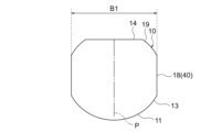
- FIG. 1 is a front view of a mold of the branch structure manufacturing apparatus according to Embodiment 1 of the present invention.
- FIG. FIG. 2 is a right side view of a mold of the branch structure manufacturing apparatus according to the first embodiment of the present invention.
- FIG. 2 is a plan view of a mold of the branch structure manufacturing apparatus according to Embodiment 1 of the present invention.
- 1 is a front sectional view of a mold of the branch structure manufacturing apparatus according to Embodiment 1 of the present invention.
- FIG. FIG. 3 is a right side sectional view of the mold of the branch structure manufacturing apparatus according to the first embodiment of the present invention.
- FIG. 2 is a front view of a drawing jig of the branch structure manufacturing apparatus according to Embodiment 1 of the present invention.
- FIG. 3 is a right side view of the drawing jig of the branch structure manufacturing apparatus according to Embodiment 1 of the present invention. It is a perspective view of the upper part of the drawing jig of the branch part structure manufacturing apparatus of Embodiment 1 of this invention.
- FIG. 3 is a front sectional view of a mold and a pipe showing a mold insertion step of the method for manufacturing a branch structure according to the first embodiment of the present invention.
- FIG. 3 is a partial cross-sectional view of a mold, a pipe, and a drawing jig, showing a first drawing jig connection step of the method for manufacturing a branch structure according to Embodiment 1 of the present invention.
- FIG. 3 is a right side view of the drawing jig of the branch structure manufacturing apparatus according to Embodiment 1 of the present invention. It is a perspective view of the upper part of the drawing jig of the branch part structure manufacturing apparatus of Embodiment 1 of this invention.
- FIG. 3 is
- FIG. 7 is a partial cross-sectional view of a mold, a pipe, and a drawing jig, showing a second drawing jig connection step of the method for manufacturing a branch structure according to Embodiment 1 of the present invention. It is a schematic diagram of the burring processing system of Embodiment 2 of the present invention. It is a schematic diagram of the burring processing system of Embodiment 3 of the present invention. It is a schematic diagram of the welding system of Embodiment 4 of this invention.
- FIG. 1 is a front view of a mold of a branch structure manufacturing apparatus according to the first embodiment.
- the mold 10 is a mold made of metal such as stainless steel alloy, special steel, and tool steel. It has a maximum diameter portion 12. The diameter at the maximum diameter portion is called the major axis A1. Note that the direction in which the major axis A1 extends, that is, the left-right direction in the drawing of FIG. 1 is referred to as the left-right direction of the mold 10. Further, a front curved surface portion 13 is formed between the front portion 11 and the maximum diameter portion 12, and a rear curved surface portion 19 is formed between the rear portion 14 and the maximum diameter portion 12.
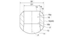
- FIG. 2 is a right side view of the mold 10 of the branch structure manufacturing apparatus according to the first embodiment.
- the mold 10 is provided with a minimum diameter portion 18 between the front portion 11 and the rear portion 14.
- the minimum diameter portion 18 is formed by cutting out a portion of one outer diameter portion of the approximately spherical mold 10 and a portion of the other opposing outer diameter portion in parallel to the extending direction of the mold center axis P. This is a flat part formed by The distance between one minimum diameter portion 18 and the other minimum diameter portion 18 is referred to as a short axis B1.
- the maximum diameter portion 12 (see FIG. 1) and the minimum diameter portion 18 constitute a central portion 40 of the mold 10 in the front-rear direction.
- FIG. 3 is a plan view of the mold 10 of the branch structure manufacturing apparatus according to the first embodiment.
- 4 is a front cross-sectional view of the mold 10 taken along line MM shown in FIG. 3
- FIG. 5 is a right side cross-sectional view taken along line NN shown in FIG. .
- the mold 10 has a through hole 16 extending from the front part 11 to the rear part 14 along the mold center axis P.
- the through hole 16 includes a deformed hole portion 17 that opens in the front portion 11 and extends from the front portion 11 along the mold center axis P, and a circular hole portion that opens in the rear portion 14 and extends from the rear portion 14 along the mold center axis P. 16a.
- the circular hole portion 16a and the deformed hole portion 17 have the mold center axis P as a common center axis, and are connected inside the mold 10. As shown in FIG. 3, the deformed hole portion 17 has a central circular portion 17a and a protruding hole portion 17b that protrudes from the central circular portion 17a along the short axis B1 direction.
- the inner peripheral portion of the deformable hole portion 17 is formed in a tapered shape whose diameter decreases from the front portion 11 side toward the rear portion 14 side.
- the diameter of the central circular portion 17a of the deformed hole portion 17 is smaller than the diameter D1 of the circular hole portion 16a, and the diameter closest to the rear portion 14 is the diameter D2.
- the diameter of the protruding hole 17b of the deformed hole 17 closest to the rear 14 is the diameter D1.
- An arcuate planar step portion 16b is formed symmetrically around the center on the side of the maximum diameter portion 12. Note that the through hole 16 constitutes a connecting hole portion, and the stepped portion 16b constitutes a key-shaped portion.
- FIG. 6 is a front view of the extraction jig of the branch structure manufacturing apparatus according to the first embodiment.
- the extraction jig 20 is made of metal such as stainless alloy, special steel, or tool steel, and includes a tip 21 that is a cylindrical rod-shaped portion, a cylindrical main body 25 that has a larger diameter than the tip 21, and a tip. It has a tapered part 23 that connects the part 21 and the main body part 25.
- the tip portion 21, the main body portion 25, and the tapered portion 23 have a common jig center axis Q.
- the diameter of the main body portion 25 is referred to as a jig diameter C1
- the diameter of the tip portion 21 is referred to as a tip diameter C2.
- the extraction jig 20 constitutes a connecting member
- the tip portion 21 constitutes an end portion.
- the jig central axis Q constitutes the connecting member central axis.
- FIG. 7 is a right side view of the extraction jig 20 of the branch structure manufacturing apparatus according to the first embodiment
- FIG. 8 is a perspective view of the upper part of the extraction jig 20 according to the first embodiment.
- a protrusion 26 is formed on the outer diameter portion of the tip portion 21 and protrudes radially outward in a direction perpendicular to the direction along the jig center axis Q.
- the tip portion 21 is formed to have a tip diameter C3 that can fit into the central circular portion 17a of the deformed hole portion 17 of the mold 10, and the protrusion portion 26 fits into the protrusion hole portion 17b of the deformed hole portion 17. It is formed to have the maximum possible width C4.
- the length of the protrusion 26 in the direction along the jig center axis Q is shorter than the length of the circular hole 16a of the mold 10 (see FIG. 4) in the direction along the mold center axis P.
- FIG. 9 is a front cross-sectional view showing a prepared hole forming step and a mold inserting step of the method for manufacturing the branch structure of a metal tube according to the first embodiment.
- the pipe 30 is a metal pipe made of any metal such as stainless steel alloy, special steel, and tool steel, which is used for piping of various fluids.
- FIG. 5 shows a cross section of the pipe 30 taken along the center of its inner diameter in the longitudinal direction. The size of the inner diameter of the pipe 30 is referred to as pipe inner diameter A2.
- a known pilot hole processing machine forms an oval spline-shaped pilot hole 31 that connects the inside and outside of the pipe 30 at a location where the branch structure of the pipe 30 is to be manufactured.
- the major axis length of the pilot hole 31 is referred to as major axis length C2.
- the long axis A1 (see FIG. 1) of the mold 10 is approximately the same length as the pipe inner diameter A2 of the pipe 30, but the long axis A1 is slightly smaller.
- the jig diameter C1 (see FIG. 6) of the main body portion 25 of the extraction jig 20 is a length that allows the main body portion 25 to be inserted into the prepared hole 31.
- the mold 10 is inserted into the end of the pipe 30 in which the pilot hole 31 is formed, and is moved to the position where the pilot hole 31 is formed.
- the mold 10 is arranged so that the direction in which the mold center axis P of the mold 10 extends and the direction in which the pilot hole 31 extends match, and the radial center of the mold center axis P and the pilot hole 31 match. is inserted.
- the maximum diameter portion 12 of the mold 10 is provided facing the pipe 30 in the longitudinal direction, and the minimum diameter portion 18 is provided perpendicularly to the longitudinal direction of the pipe 30, that is, facing the inner surface of the pipe 30. The mold 10 is inserted so as to do so.
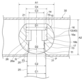
- FIG. 10 is a front cross-sectional view showing the first drawing jig connection step of the method for manufacturing the branch structure of a metal tube according to the first embodiment.
- the tip part 21 when the tip part 21 is further inserted in the direction of the mold 10, the tip part 21 fits into the central circular part 17a, and the protruding part 26 fits into the protruding hole part 17b (see FIG. 3). , the protrusion 26 is inserted until the lower end 26a is at the same height as the step 16b of the mold 10.
- the inner peripheral portion of the deformable hole portion 17 is formed in a tapered shape whose diameter decreases from the front portion 11 side toward the rear portion 14 side. Therefore, even if the installation position of the mold 10 is shifted with respect to the prepared hole 31 of the pipe 30 and the position of the deformed hole 17 is shifted with respect to the prepared hole 31, the deformed hole 17
- the mold 10 By inserting the tip 21 of the drawing jig 20 into the pipe, the mold 10 moves within the pipe 30 so that the mold center axis P and the jig center axis Q coincide, and the mold 10 is aligned. will be done.
- FIG. 11 is a front sectional view showing the second drawing jig connection step of the method for manufacturing the metal tube branch structure of the first embodiment.
- the first burring process is performed.
- a known burring machine (not shown) pulls out the drawing jig 20 radially outward along the direction in which the pilot hole 31 of the pipe 30 extends.
- the mold 10 is pulled out to the outside of the pipe 30 while the edge of the pilot hole 31 is pulled outward in the radial direction of the pipe 30 by the front curved surface portion 13 of the mold 10 connected to the drawing jig 20. It will be done.
- the pilot hole 31 is expanded to the maximum diameter portion 12 of the mold 10 in the longitudinal direction of the pipe 30, forming an opening having the same length as the major axis A1.
- Ru In the direction perpendicular to the longitudinal direction of the pipe 30, the prepared hole 31 is expanded to the minimum diameter portion 18 of the mold 10 to form an opening having the same length as the short diameter B1.
- a burring machine (not shown) rotates the mold 10 90 degrees clockwise by rotating the drawing jig 20 90 degrees clockwise.
- the burring machine inserts the tip 21 of the drawing jig 20 to which the mold 10 is connected into the pipe 30 through the prepared hole 31 of the pipe 30.
- the mold 10 is reinserted into the pipe 30 through the pilot hole 31.
- the opening portion of the prepared hole 31 of the pipe 30 having the same length as the short diameter B1 comes into contact with the maximum diameter portion 12 from the rear curved surface portion 19 of the mold 10 and is pushed out.
- this opening is expanded until it becomes the same as the major axis A1, which is the length of the maximum diameter portion 12, and this opening is formed into a circular shape whose diameter is the same as the major axis A1, and the second burring is performed. Processing is completed.
- the burring machine pulls out the drawing jig 20 in a radially outward direction along the direction in which the pilot hole 31 of the pipe 30 extends.
- connection and disconnection between the mold 10 and the drawing jig 20 can be performed either inside or outside the pipe 30 as necessary.
- the branch structure manufacturing apparatus has a spherical shape that extends perpendicularly to the extending direction of the mold center axis P and has a major axis A1 and a minor axis B1 shorter than the major axis A1.
- a mold 10 having a shape, a through hole 16 formed in the mold 10 to extend along the mold center axis P, a drawing jig 20 connectable to the mold 10, and a tip of the drawing jig 20.
- the prepared hole 31 that radially penetrates the tube body of the pipe 30 is subjected to a first burring process using the mold 10, and the extraction jig 20 pulls the removed mold 10 around the mold center axis P.
- the mold inserted into the metal pipe and the drawing jig are shortened. It is possible to connect them in a working time, and therefore the time required for the entire burring process can be shortened.
- the through hole 16 has a deformed hole portion 17 and a step portion 16b formed inside the mold 10, and the tip portion 21 is located at a first rotation angle about the jig central axis Q.
- the protruding part 26 is inserted into the deformed hole part 17, the protruding part 26 of the distal end part 21 is inserted into the through hole 16 when the distal end part 21 is located at the second rotation angle about the jig central axis Q. Since it can be fitted into the stepped portion 16b, it can be easily configured and used in a branch structure manufacturing device that connects the threaded portion of the spherical mold 10 and the extraction jig 20 by threading the threaded portion. The mold and the drawing jig can be connected in a short working time.
- the method for manufacturing the branch structure of a metal pipe according to the first embodiment includes a first step of forming a prepared hole 31 that radially penetrates the body of the pipe 30 at a branch formation position of the pipe 30. and a spherical shape having a mold center axis P, a first diameter extending perpendicularly to the extending direction of the mold center axis P, and a second diameter shorter than the first diameter.
- the fifth step of rotating the direction of the metal pipe by a predetermined angle around the mold center axis P and performing a second burring process on the pilot hole 31 from the outside of the pipe 30 using the mold 10 The inserted mold and the drawing jig can be connected in a short working time, and therefore the time required for the entire burring process can be shortened.
- the mold 10 had a truncated spherical outer shape having a pair of opposing minimum diameter portions 18 extending parallel to the mold center axis P; As long as the mold 10 has the stepped portion 16b and the deformed hole portion 17, the mold 10 may have an arbitrary external shape such as an ellipsoidal shape or a shape having a notch.
- the protruding portion 26 of the drawing jig 20 extends in a direction perpendicular to the direction along the jig center axis Q, and the stepped portion 16b of the mold 10 extends along the mold center axis P. Although it extends in a direction perpendicular to the direction along it, it is not limited thereto.
- the protruding part 26 may extend in a direction other than perpendicular to the direction along the jig center axis Q, and the stepped part 16b It may extend in a direction at an angle other than perpendicular to the direction along the mold center axis P.
- the mold 10 had the through hole 16, but instead of the through hole 16, it may have a non-through hole whose rear portion 14 side is closed. Furthermore, this through hole 16 or non-through hole is used to insert the tip 21 of the drawing jig 20 with the mold 10 connected into the inside of the pipe 30 from the pilot hole 31 of the pipe 30 before the second burring process.
- the mold 10 may have a stopper portion (not shown) that prevents movement toward the rear portion 14 from the matching position.
- the drawing jig 20 extracts the mold 10 to the outside of the pipe 30, but the method is not limited to this.
- the drawing jig 20 pulls out the mold 10 radially outward along the extending direction of the prepared hole 31 of the pipe 30, and the front curved surface of the mold 10 13, the edge of the prepared hole 31 is pulled out in the radially outward direction of the pipe 30 into the desired first burring shape.
- the extraction jig 20 returns the mold 10 to the inside of the pipe 30 without removing the entire mold 10 to the outside of the pipe 30.
- a burring machine (not shown) rotates the drawing jig 20 90 degrees clockwise, thereby rotating the mold 10 90 degrees clockwise.
- the drawing jig 20 pulls the mold 10 outward in the radial direction along the extending direction of the prepared hole 31 of the pipe 30, and the front curved surface part 13 of the mold 10
- this opening is expanded until it becomes the same as the major axis A1, which is the length of the maximum diameter portion 12, and this opening is formed into a circular shape whose diameter is the same as the major axis A1, and the second burring is performed. Processing is completed.
- the extraction jig 20 does not extract the entire mold 10 to the outside of the pipe 30, and the edge of the prepared hole 31 is radially outward of the pipe 30.
- the drawing jig 20 may return the mold 10 to the inside of the pipe 30.
- the connection between the drawing jig 20 and the mold 10 is released, and a moving device (not shown) for the mold 10 moves the prepared hole 31 for the next burring process.
- the mold 10 may move through the inside of the pipe 30 to the position shown in FIG.
- the mold 10 is not removed to the outside of the pipe 30 each time the burring process is performed on each prepared hole 31, so that the work for reinserting the mold 10 from the outside of the pipe 30 is required. Man-hours and work time can be reduced.
- the mold 10 was inserted into the pipe 30 from the outside of the pilot hole 31 of the pipe 30, but the mold 10 was inserted into the pipe 30 from the outside of the pilot hole 31 of the pipe 30. Similarly to the mold insertion process, the mold 10 may be inserted into the pipe 30 from the end of the pipe 30.
- the inner peripheral part of the deformed hole part 17 of the mold 10 of the first embodiment was formed in a tapered shape in which the diameter decreases from the front part 11 side to the rear part 14 side, but the angle of this taper is not necessary.
- the inner peripheral part of the deformed hole part 17 may not be tapered but may be formed substantially parallel to the mold center axis P.
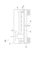
- FIG. 12 is a schematic diagram of a burring processing system according to the second embodiment.
- the burring system 50 includes a truck 51 with a loading platform 52.
- a rack slider 54 and a support member 55 that supports the pipe 30 are mounted on the loading platform 52.
- a branch structure manufacturing device 53 is installed on the rack slider 54 .
- the branch structure manufacturing device 53 is a branch structure manufacturing device according to Embodiment 1 of the present application, and forms the burring portion 32 on the pipe 30. Further, the branch structure manufacturing device 53 is provided so as to be movable along the longitudinal direction E of the pipe 30 on a rail on a rack slider 54. An outrigger 56 is provided on the side surface of the truck 51. Note that the burring processing system 50 constitutes a branch structure manufacturing system, and the rack slider 54 constitutes a support rail. The other configurations are the same as in the first embodiment.
- the burring system including the branch structure manufacturing device 53 was installed in a factory. Therefore, when manufacturing and installing a pipe with a branch structure, the raw pipe to be burred is transported to a factory equipped with a burring system, and the burring system forms the branch structure on the pipe. Then, the pipe with the branch structure was transported to the installation site and installed at the installation location. Therefore, it is necessary to perform burring on the pipe at a factory and then transport the burred pipe to the installation site, which requires transportation costs and time.
- a branch structure manufacturing device 53 a rack slider 54, and a support member 55 are mounted on a truck 51 on a loading platform 52, and this truck 51 can be moved to any site.
- the worker moves the truck 51 to an arbitrary site where burring is to be performed and parks it, the worker extends the outrigger 56 of the truck 51, supports the raw pipe 30 to be burred by the support member 55, and moves the truck 51 to the loading platform 52.
- the pipe 30 can be burred by the branch structure manufacturing device 53.
- the burring processing system 50 has a burring system 50 that is formed in the inside of the pipe 30 with respect to the prepared hole 31 that radially penetrates the pipe body of the pipe 30, which is formed at the branch part forming position of the pipe 30.
- a branch structure manufacturing device 53 that extracts the inserted mold 10 to the outside of the pipe 30 and performs burring processing using the mold 10, and a branch structure manufacturing device 53 that is movable along the longitudinal direction of the pipe 30. It includes a rack slider 54 to support, and a truck 51 on which the branch structure manufacturing device 53 and the rack slider 54 are loaded.
- FIG. 13 is a schematic diagram of a burring processing system according to the third embodiment.
- the burring processing system 50a has a railway vehicle 57 including a bogie 58.
- a rack slider 54 and a support member 55 that supports the pipe 30 are mounted on the truck 58.
- a branch structure manufacturing device 53 is installed on the rack slider 54 .
- the truck 58 is provided with an outrigger 56.
- the other configurations are the same as in the second embodiment.
- the burring processing system 50a according to the third embodiment includes the branch structure manufacturing device 53, the rack slider 54 that supports the branch structure manufacturing device 53 so as to be movable along the longitudinal direction of the pipe 30, A railway vehicle 57 is provided on which a branch structure manufacturing device 53 and a rack slider 54 are loaded. Therefore, similar to the branch manufacturing system according to the second embodiment, it is possible to manufacture the branch structure by burring at the site where the pipe 30 is used, and similarly to the branch manufacturing system according to the second embodiment. The effect of this can be obtained.
- branch structure manufacturing apparatus 53 according to Embodiment 2 and Embodiment 3 of the present application is the branch structure manufacturing apparatus according to Embodiment 1 of the present application, it is not limited to this, and for example, Any branch structure manufacturing apparatus, such as the branch structure manufacturing apparatus described in Document 1, can be used.
- FIG. 14 is a schematic diagram of a welding system according to Embodiment 4.
- a welding device 63 is installed on a rack slider 54 mounted on a loading platform 52 of a truck 51.
- the welding device 63 welds the branch side metal pipe 35 to the burring portion 32 of the pipe 30, and is provided so that the rail on the rack slider 54 can be freely moved along the longitudinal direction E of the pipe 30.
- the other configurations are the same as in the second embodiment.
- This welding system 60 can be moved to any site by a truck 51 carrying a welding device 63, a rack slider 54, and a support member 55 on a loading platform 52. After the worker moves the truck 51 to an arbitrary site and parks it, the outrigger 56 of the truck 51 is extended, and the branch structure manufacturing device 53 according to the second embodiment or the third embodiment (see FIGS. 12 and 13) The pipe 30 subjected to the burring process can be mounted on the support member 55, and the branch metal pipe 35 can be welded to the burring part 32 on the loading platform 52.
- the welding system 60 of the fourth embodiment has the advantage that the cost and man-hours required for manufacturing and installing the pipe 30 in which the branch metal pipe 35 is welded to the burring portion 32 can be reduced.
- the welding system 60 is inserted into the pipe 30 through the prepared hole 31 that radially penetrates the pipe body of the pipe 30 and is formed at the branching portion forming position of the pipe 30.
- a welding device 63 that welds the branch metal pipe 35 to the branch structure formed by the branch structure manufacturing device which extracts the mold 10 to the outside of the pipe 30 and performs burring using the die 10; It includes a rack slider 54 that supports the welding device 63 movably along the longitudinal direction E of the pipe 30, and a vehicle that loads the welding device 63 and the rack slider 54.
- the welding device 63 and the rack slider 54 are loaded on the truck 51, but the vehicle on which the welding device 63 and the rack slider 54 are mounted is limited to the truck 51. It's not something you can do.
- the welding device 63 and the rack slider 54 may be mounted on the railway vehicle 57.
Landscapes
- Engineering & Computer Science (AREA)
- Mechanical Engineering (AREA)
- Physics & Mathematics (AREA)
- Optics & Photonics (AREA)
- Branch Pipes, Bends, And The Like (AREA)
Priority Applications (2)
| Application Number | Priority Date | Filing Date | Title |
|---|---|---|---|
| PCT/JP2022/024475 WO2023248274A1 (ja) | 2022-06-20 | 2022-06-20 | 金属管の分岐部構造製造装置、分岐部構造製造システム及び溶接システム、並びに金属管の分岐部構造の製造方法 |
| JP2024528087A JP7820852B2 (ja) | 2022-06-20 | 2022-06-20 | 金属管の分岐部構造製造装置、分岐部構造製造システム及び溶接システム、並びに金属管の分岐部構造の製造方法 |
Applications Claiming Priority (1)
| Application Number | Priority Date | Filing Date | Title |
|---|---|---|---|
| PCT/JP2022/024475 WO2023248274A1 (ja) | 2022-06-20 | 2022-06-20 | 金属管の分岐部構造製造装置、分岐部構造製造システム及び溶接システム、並びに金属管の分岐部構造の製造方法 |
Publications (1)
| Publication Number | Publication Date |
|---|---|
| WO2023248274A1 true WO2023248274A1 (ja) | 2023-12-28 |
Family
ID=89379564
Family Applications (1)
| Application Number | Title | Priority Date | Filing Date |
|---|---|---|---|
| PCT/JP2022/024475 Ceased WO2023248274A1 (ja) | 2022-06-20 | 2022-06-20 | 金属管の分岐部構造製造装置、分岐部構造製造システム及び溶接システム、並びに金属管の分岐部構造の製造方法 |
Country Status (2)
| Country | Link |
|---|---|
| JP (1) | JP7820852B2 (https=) |
| WO (1) | WO2023248274A1 (https=) |
Citations (3)
| Publication number | Priority date | Publication date | Assignee | Title |
|---|---|---|---|---|
| JPS5913530A (ja) * | 1982-07-13 | 1984-01-24 | Toshiba Corp | 分岐管の拡管成形方法 |
| JPS6174727A (ja) * | 1984-09-19 | 1986-04-17 | Hitachi Ltd | 管のバ−リング加工方法 |
| JPH0390221A (ja) * | 1989-08-31 | 1991-04-16 | Nippon Pipe Seizo Kk | 管状部材のバーリング方法 |
-
2022
- 2022-06-20 WO PCT/JP2022/024475 patent/WO2023248274A1/ja not_active Ceased
- 2022-06-20 JP JP2024528087A patent/JP7820852B2/ja active Active
Patent Citations (3)
| Publication number | Priority date | Publication date | Assignee | Title |
|---|---|---|---|---|
| JPS5913530A (ja) * | 1982-07-13 | 1984-01-24 | Toshiba Corp | 分岐管の拡管成形方法 |
| JPS6174727A (ja) * | 1984-09-19 | 1986-04-17 | Hitachi Ltd | 管のバ−リング加工方法 |
| JPH0390221A (ja) * | 1989-08-31 | 1991-04-16 | Nippon Pipe Seizo Kk | 管状部材のバーリング方法 |
Also Published As
| Publication number | Publication date |
|---|---|
| JP7820852B2 (ja) | 2026-02-26 |
| JPWO2023248274A1 (https=) | 2023-12-28 |
Similar Documents
| Publication | Publication Date | Title |
|---|---|---|
| CN105555639B (zh) | 用于转向轴的导向管及其制造方法 | |
| US20090152898A1 (en) | Pipe member and method of manufacturing the same | |
| MXPA03002378A (es) | Accesorio interno forjado en matriz. | |
| EP3604087B1 (en) | Vehicle structural member and method for producing same | |
| WO2023248274A1 (ja) | 金属管の分岐部構造製造装置、分岐部構造製造システム及び溶接システム、並びに金属管の分岐部構造の製造方法 | |
| US3838592A (en) | Hose end fittings and inserts therefor | |
| EP2375017B1 (de) | Verfahren zur Herstellung eines Fahrzeugschalldämpfers und Fahrzeugschalldämpfer | |
| JP2008051237A (ja) | 複数のパイプの連結構造体 | |
| EP3238849A1 (en) | Method for manufacturing wide-mouthed metal pipe | |
| KR102218893B1 (ko) | 편심 자유적용 이음쇠 기구 및 편심 자유적용 이음쇠 | |
| EP3067130A1 (en) | Sub-muffler | |
| CN103492701B (zh) | 管形蓄压器 | |
| JP2818933B2 (ja) | 管溶接用インサート金具及びこれを使用してなる管溶接構造 | |
| US20120169047A1 (en) | Method of forming an internal tube beadlock | |
| US12318833B2 (en) | Apparatus for producing branch structure in metal pipe, and method for producing branch structure in metal pipe | |
| JP3636956B2 (ja) | 配管継手の抜け止め孔加工用治具及び加工方法 | |
| EP3492719B1 (de) | Gehäuseanschlusselement | |
| US9091376B2 (en) | Method of forming an internal tube beadlock | |
| JP4493860B2 (ja) | 接合構造 | |
| US10634036B2 (en) | Method for molding pipe body | |
| JP2639987B2 (ja) | 細径金属管の接続方法 | |
| US3268247A (en) | Pipe joint constructions and methods of making the same or the like | |
| JP6447466B2 (ja) | 車両用サスペンションアームの製造方法 | |
| JP4940620B2 (ja) | 二重管分岐構造およびその製造方法 | |
| US2119448A (en) | Fitting |
Legal Events
| Date | Code | Title | Description |
|---|---|---|---|
| 121 | Ep: the epo has been informed by wipo that ep was designated in this application |
Ref document number: 22947838 Country of ref document: EP Kind code of ref document: A1 |
|
| WWE | Wipo information: entry into national phase |
Ref document number: 2024528087 Country of ref document: JP |
|
| NENP | Non-entry into the national phase |
Ref country code: DE |
|
| 122 | Ep: pct application non-entry in european phase |
Ref document number: 22947838 Country of ref document: EP Kind code of ref document: A1 |