WO2023243288A1 - オゾン含有ガス発生方法、オゾン含有ガス発生システム - Google Patents
オゾン含有ガス発生方法、オゾン含有ガス発生システム Download PDFInfo
- Publication number
- WO2023243288A1 WO2023243288A1 PCT/JP2023/018242 JP2023018242W WO2023243288A1 WO 2023243288 A1 WO2023243288 A1 WO 2023243288A1 JP 2023018242 W JP2023018242 W JP 2023018242W WO 2023243288 A1 WO2023243288 A1 WO 2023243288A1
- Authority
- WO
- WIPO (PCT)
- Prior art keywords
- ozone
- gas
- containing gas
- light source
- ultraviolet light
- Prior art date
- Legal status (The legal status is an assumption and is not a legal conclusion. Google has not performed a legal analysis and makes no representation as to the accuracy of the status listed.)
- Ceased
Links
Images




Classifications
-
- C—CHEMISTRY; METALLURGY
- C01—INORGANIC CHEMISTRY
- C01B—NON-METALLIC ELEMENTS; COMPOUNDS THEREOF; METALLOIDS OR COMPOUNDS THEREOF NOT COVERED BY SUBCLASS C01C
- C01B13/00—Oxygen; Ozone; Oxides or hydroxides in general
- C01B13/10—Preparation of ozone
-
- H—ELECTRICITY
- H01—ELECTRIC ELEMENTS
- H01J—ELECTRIC DISCHARGE TUBES OR DISCHARGE LAMPS
- H01J65/00—Lamps without any electrode inside the vessel; Lamps with at least one main electrode outside the vessel
-
- H—ELECTRICITY
- H01—ELECTRIC ELEMENTS
- H01T—SPARK GAPS; OVERVOLTAGE ARRESTERS USING SPARK GAPS; SPARKING PLUGS; CORONA DEVICES; GENERATING IONS TO BE INTRODUCED INTO NON-ENCLOSED GASES
- H01T23/00—Apparatus for generating ions to be introduced into non-enclosed gases, e.g. into the atmosphere
Definitions
- the present invention relates to a method of generating an ozone-containing gas, and particularly to a method of generating an ozone-containing gas at a pressure higher than atmospheric pressure.
- the invention also relates to a system suitable for implementing such a method.
- Patent Document 1 Conventionally, a technique for supplying ozone to treat wastewater containing organic matter has been known (for example, see Patent Document 1).
- Patent Document 1 has restrictions on the conditions under which it can be used. This point will be explained below.
- the viscosity of wastewater to be treated changes depending on the type and density of organic matter contained, including activated sludge.
- the pressure of the gas changes depending on the viscosity of the liquid.
- the pressure of the gas to be supplied is also affected by what kind of device is employed as the means for supplying the gas.
- the pressure of the supplied gas changes depending on whether the gas is supplied by an ejector or by a diffuser plate.
- the pressure of the supplied gas is also affected by the diameter of the hole through which the gas is injected.
- the system proposed in Patent Document 1 uses a silent discharge type ozone generator.
- the pressure of the raw material gas for generating the ozone-containing gas increases. Paschen's law holds between the discharge starting voltage and the gas pressure in the discharge space. That is, when the pressure of the raw material gas increases, the discharge starting voltage also increases.
- the power supply circuit is usually equipped with a transformer.
- the voltage can be adjusted by adjusting the transformation ratio of the transformer.
- adjusting the transformer ratio requires adjusting the turns ratio of the transformer, and since there is a limit to the adjustment range of the turns ratio, as a result, there is a restriction on the fluctuation range of the output voltage.
- the thickness of the insulator and the spatial distance must be ensured, so it is necessary to increase the size of the device in order to handle the high voltage.
- the patent document 1 described above is applicable not only to the treatment of highly viscous wastewater but also to situations where ozone-containing gas is injected into a liquid at high pressure to generate a liquid in which the ozone-containing gas is microbubbled.
- the proposed system has limitations. This is because, as mentioned above, in the system proposed in Patent Document 1, restrictions are imposed on the pressure applied to the raw material gas, making it difficult to generate ozone-containing gas with the pressure necessary for forming microbubbles. Because it will be.
- the present invention aims to provide a method and system that can produce ozone-containing gas with a higher pressure than conventional ones with a simple structure.
- the ozone-containing gas generation method includes a step (a) of introducing a raw material gas containing oxygen into an ozone generation space at a pressure higher than atmospheric pressure; a step (b) of irradiating the raw material gas with ultraviolet light having a peak wavelength of less than 200 nm emitted from an ultraviolet light source in the ozone generation space; It is characterized by comprising a step (c) of exhausting the ozone-containing gas at a pressure higher than atmospheric pressure, which is generated in the step (b), to the outside of the ozone generation space.
- the above method is a method in which an ozone-containing gas is generated by irradiating an oxygen-containing source gas with ultraviolet rays, unlike a method in which an ozone-containing gas is generated by causing a discharge in a source gas. Therefore, Paschen's law is not applied to the pressure of the source gas. Therefore, it becomes possible to increase the pressure of the raw material gas introduced into the ozone generation space. Furthermore, unlike a discharge-type ozone generator, even if the pressure of the raw material gas fluctuates, the generation of ozone-containing gas is not affected.
- the ultraviolet light source is configured to emit ultraviolet light in a wavelength range that has relatively high absorbency for oxygen molecules. Typically, the peak wavelength of the ultraviolet light is less than 200 nm.
- a dielectric barrier discharge type lamp such as an excimer lamp, or a solid state light source such as an LED can be used.
- Oxygen molecules have an absorption region called Schumann-Runge Bands in the ultraviolet region below 200 nm. Therefore, when oxygen molecules contained in the raw material gas introduced into the ozone generation space are irradiated with ultraviolet light having a wavelength of less than 200 nm, they are decomposed into atomic oxygen according to the following formula (1).
- M represents a third body (the same applies hereinafter).
- high-pressure gas containing ozone is generated through equations (1) and (2) above. According to the above method, high-pressure ozone-containing gas is generated within the ozone generation space and exhausted to the outside of the ozone generation space.
- the step (a) may be a step of introducing the raw material gas into the ozone generation space at a pressure higher than 0.2 MPa.
- the pressure of the source gas can be 0.25 MPa to 0.95 MPa.
- the pressurized air can be used as a raw material gas, or after separating oxygen and nitrogen from the pressurized air, the separated gas containing oxygen as the main component can be used as a raw material gas. You can also use it. In either case, it is possible to generate ozone-containing gas using the raw material gas whose pressure is adjusted on the compressor side.
- the ozone-containing gas generation method includes a step (d) of flowing cooling gas through a light source arrangement space in which the ultraviolet light source is arranged,
- the light source arrangement space and the ozone generation space may be arranged adjacent to each other across a wall made of a material that is transparent to ultraviolet rays.
- the ultraviolet light source is composed of an excimer lamp
- a small space may be created between the tube wall of the excimer lamp and the electrode, into which gas may enter.
- the space in which the excimer lamp is placed (light source placement space) and the ozone generation space are common, that is, if the excimer lamp is placed in the ozone generation space where the raw material gas is introduced, There is a possibility that high-pressure raw material gas enters the minute space. At this time, there is a concern that the discharge starting voltage of the excimer lamp will increase.
- the space in which the ultraviolet light source is arranged is separate from the ozone generation space into which the high-pressure raw material gas is introduced, so that the high-pressure raw material gas is introduced. Also, the influence on the discharge starting voltage can be avoided regardless of the structure of the electrodes included in the ultraviolet light source.
- the ozone-containing gas generation method includes a step (e) of separating pressurized air into the raw material gas and a non-raw material gas containing nitrogen;
- the step (a) is a step of introducing the raw material gas separated in the step (e) into the ozone generation space,
- the step (d) may be a step of flowing the non-source gas separated in the step (e) into the light source arrangement space as the cooling gas.
- the case where ozone-containing gas is generated by irradiating ultraviolet rays on raw material gas after nitrogen has been separated from pressurized air. has higher ozone generation efficiency.
- the pressurized raw material gas whose main component is oxygen is introduced into the ozone generation space, so that high ozone generation efficiency is achieved.
- the separated nitrogen-containing gas can be used as a cooling gas for the excimer lamp.
- the ozone-containing gas generation system includes: an ultraviolet light source that emits ultraviolet light with a peak wavelength of less than 200 nm; a first introduction port through which a source gas containing oxygen is introduced at a pressure higher than atmospheric pressure; an ozone generation space connected to the first inlet and irradiated with the ultraviolet light from the ultraviolet light source; A first inlet is connected to the ozone generation space at a location different from the first inlet, and the ozone-containing gas that is the raw material gas after being irradiated with the ultraviolet rays is discharged at a pressure higher than atmospheric pressure. It is characterized by being equipped with one exhaust port.
- high pressure ozone-containing gas can be generated and exhausted. Therefore, by injecting the high-pressure ozone-containing gas obtained with this system into liquids that require sterilization and cleaning, such as waste water and liquid foods (e.g., concentrated fruit juice), sterilization and cleaning can be easily performed. It can be carried out.
- waste water and liquid foods e.g., concentrated fruit juice
- water with high sterilization and cleaning ability water containing ozone bubbles
- water containing ozone bubbles water containing ozone bubbles
- the ultraviolet light source may be placed within the ozone generation space. In this configuration, the raw material gas flows through the space in which the ultraviolet light source is arranged.
- the ozone-containing gas generation system includes: A casing and a pipe body disposed within the housing and made of a material that is transparent to the ultraviolet rays; the housing includes the first inlet, the ozone generation space, and the first exhaust port; the ultraviolet light source is housed within the tube; The ultraviolet rays from the ultraviolet light source may be irradiated into the ozone generation space through the tube wall of the tube body. .
- high-pressure source gas does not flow through the space where the ultraviolet light source is located. Therefore, regardless of the shape of the electrodes included in the ultraviolet light source, a situation in which the discharge voltage of the ultraviolet light source increases due to the passage of high-pressure raw material gas can be avoided.
- the pipe body includes a second introduction port through which cooling gas is introduced, a light source arrangement space that is connected to the second introduction port and in which the ultraviolet light source is arranged, and the cooling gas after passing through the light source arrangement space. It is also possible to have a second exhaust port through which the gas is exhausted.
- the ozone generation space may be arranged outside the tube body.
- the ozone-containing gas generation system includes a housing,
- the ultraviolet light source has a tube body disposed within the housing and including an inner tube and an outer tube,
- the housing includes the first inlet, the ozone generation space, and the first exhaust port, and the ozone generation space may be located inside the inner tube.
- the ozone-containing gas generation system includes a gas separation device that separates pressurized air into the raw material gas whose main component is oxygen and the non-raw material gas whose main component is nitrogen,
- the raw material gas separated by the gas separation device is introduced into the first pipe body through the first introduction port,
- the non-source gas separated by the gas separation device may be introduced into the second pipe body through the second introduction port.
- the ozone-containing gas generation system includes a compressor that pressurizes air to a pressure higher than 0.2 MPa, Pressurized air obtained by the compressor may be introduced into the first introduction port as the raw material gas.
- the ozone-containing gas generation system includes a compressor that pressurizes air to a pressure higher than 0.2 MPa, The pressurized air obtained by the compressor may be supplied to the gas separation device.
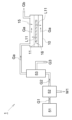
- FIG. 1 is a block diagram schematically showing the configuration of a first embodiment of an ozone-containing gas generation system.
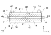
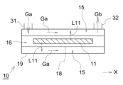
- 2 is a schematic side view of the ozone generator 10 in FIG. 1.
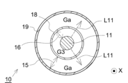
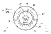
- FIG. 3 is a schematic cross-sectional view of the ozone generator 10 shown in FIG. 2 taken along a plane perpendicular to the X direction.
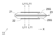
- 3 is a schematic side view of the excimer lamp 11 in FIG. 2.
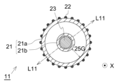
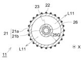
- FIG. FIG. 5 is a schematic cross-sectional view of the excimer lamp 11 in FIG. 4 taken along a plane perpendicular to the X1 direction. 5 is another schematic cross-sectional view of the excimer lamp 11 in FIG. 4 taken along a plane perpendicular to the X1 direction.
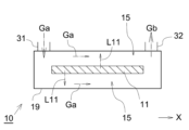
- FIG. 1 is a diagram schematically showing an example of a usage mode of high-pressure ozone-containing gas Gb. It is a drawing which shows typically another example of the utilization aspect of high-pressure ozone containing gas Gb. It is a drawing schematically showing the configuration of an ozone generator 10 according to a second embodiment. It is a schematic cross-sectional view when the ozone generator 10 shown in FIG. 9 is cut along a plane orthogonal to the X direction. 10 is a schematic side view of the excimer lamp 11 in FIG. 9. FIG. FIG. 12 is a schematic cross-sectional view of the excimer lamp 11 in FIG. 11 taken along a plane perpendicular to the X1 direction.
- FIG. 14 is a schematic cross-sectional view of the ozone generator 10 shown in FIG. 13 taken along a plane perpendicular to the X direction.
- FIG. 14 is another schematic cross-sectional view of the ozone generator 10 shown in FIG. 13 taken along a plane perpendicular to the X direction.
- FIG. 3 is a block diagram schematically showing the configuration of a fourth embodiment of an ozone-containing gas generation system.
- 17 is a schematic side view of the ozone generator 10 in FIG. 16.
- FIG. 17 is a schematic side view of the ozone generator 10 in FIG. 16.
- FIG. 1 is a block diagram schematically showing the configuration of a first embodiment of an ozone-containing gas generation system.
- the system 1 shown in FIG. 1 includes a compressor 51, a dehumidifier 52, a gas separation device 53, and an ozone generator 10.
- the compressor 51 is a device that applies pressure to supplied gas to generate high-pressure gas.
- the explanation will be given assuming that the compressor 51 generates the high-pressure air G1.
- the compressor 51 a known device can be used.
- the compressor 51 generates high-pressure air G1 with a pressure higher than 0.2 MPa.
- the high pressure air G1 exhibits a pressure of 0.25 MPa to 0.95 MPa.
- the dehumidifying device 52 is a device that removes moisture W1 contained in the high-pressure air G1 sent out from the compressor 51. However, in the present invention, whether or not the system 1 includes the dehumidifier 52 is optional. In the system 1 shown in FIG. 1, high-pressure air G2 after dehumidification is sent to the gas separation device 53.
- the gas separation device 53 separates nitrogen contained in the high pressure air G2.
- a device using a membrane separation method, a cryogenic separation method, or an adsorption separation method can be used.
- a membrane separation method that allows the simplest separation can be preferably employed.
- the gas separation device 53 using a membrane separation method is sometimes referred to as an "N 2 separator.”
- the membrane separation method has a simpler device structure than the cryogenic separation method or the adsorption separation method, the accuracy of nitrogen separation is lower. For this reason, when generating ozone-containing gas from air using a silent discharge type ozone generator, it is not practical to use the membrane separation type gas separation device 53.
- the present system 1 generates ozone-containing gas by irradiating the oxygen-containing gas with ultraviolet light L11 from an ultraviolet light source (excimer lamp 11).
- ultraviolet light L11 from an ultraviolet light source (excimer lamp 11).
- Nitrogen molecules absorb only light of very short wavelengths (less than 100 nm). Therefore, by setting the peak wavelength of the ultraviolet light L11 from the excimer lamp 11 to 140 nm to 200 nm, even if the raw material gas contains nitrogen, the ultraviolet light L11 from the excimer lamp 11 converts nitrogen molecules into nitrogen molecules. It does not separate into atoms.
- the present system 1 does not necessarily need to include the gas separation device 53.
- the gas separation device 53 it is preferable to use the gas separation device 53 to separate nitrogen gas from the high-pressure air G2.
- the gas that is separated from the high-pressure air G2 and whose main component is oxygen is referred to as "raw material gas Ga,” and the gas whose main component is nitrogen is called “non-raw material gas G3.”
- the term “main component” refers to a substance containing the highest proportion of molecules in the gas.
- the source gas Ga and the non-source gas G3 are in a high pressure state similar to the high pressure air G2. However, the non-source gas G3 does not necessarily need to be at high pressure.
- step (e) The step of separating the high-pressure air G2 into raw material gas Ga and non-raw material gas G3 by the gas separation device 53 corresponds to step (e).
- both the source gas Ga and the non-source gas G3 are sent to the ozone generator 10.
- the piping system through which the raw material gas Ga flows and the piping system through which the non-raw material gas G3 flows are different.
- the ozone generator 10 has an excimer lamp 11.
- the ozone generator 10 included in the system 1 shown in FIG. 1 is provided with a space for processing the raw material gas Ga (ozone generation space 15) and a space in which the excimer lamp 11 is arranged (light source arrangement space 16). ing.
- the ozone generation space 15 and the light source arrangement space 16 are separated by a wall made of a material that is transparent to ultraviolet light L11 from the excimer lamp 11.
- the excimer lamp 11 is an example of an ultraviolet light source.
- FIG. 2 is an enlarged view of the ozone generator 10 in FIG. 1.
- high-pressure raw material gas Ga is introduced into the ozone generation space 15 that the ozone generator 10 has. This step corresponds to step (a).
- a non-source gas G3 is introduced into the light source arrangement space 16 of the ozone generator 10.
- the high-pressure raw material gas Ga introduced into the ozone generation space 15 is irradiated with ultraviolet light L11 from the excimer lamp 11 while flowing through the ozone generation space 15 in the X direction. This step corresponds to step (b).
- the excimer lamp 11 is configured to emit ultraviolet light L11 with a peak wavelength of less than 200 nm.
- the peak wavelength of the excimer lamp 11 is around 172 nm.
- the wavelength of the ultraviolet light L11 can be varied. For example, as follows.
- the peak wavelength of the ultraviolet light L11 is around 146 nm.
- the peak wavelength of the ultraviolet light L11 is around 165 nm.
- the peak wavelength of the ultraviolet light L11 is around 193 nm.
- the expression “nearby” allows for the possibility that individual differences of about ⁇ 2 nm may occur in the peak wavelength due to the partial pressure of the gas sealed in the lamp and changes over time due to use. It's the intention.
- the ozone generator 10 has a housing 19.
- the material of the housing 19 is arbitrary, it is made of metal such as stainless steel, for example.
- the housing 19 is provided with a first inlet 31 for introducing the high-pressure source gas Ga and a first exhaust port 32 for exhausting the generated ozone-containing gas Gb.
- the casing 19 is provided with a second inlet 35 for introducing the non-raw material gas G3 and a second exhaust port 36 for exhausting the non-raw material gas G3 that has passed through the casing 19. ing.
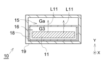
- FIG. 3 is a schematic cross-sectional view of the ozone generator 10 shown in FIG. 2 taken along a plane perpendicular to the X direction.
- a cylindrical tube 18 is disposed within the housing 19.
- the excimer lamp 11 is arranged within this tube body 18.
- the tube body 18 is made of a material that is transparent to the ultraviolet light L11 emitted from the excimer lamp 11. Typically, tube 18 is made of synthetic quartz glass.
- the ozone generation space 15 corresponds to the space surrounded by the inner wall of the housing 19 and the outer wall of the tube 18, and the light source arrangement space 16 corresponds to the space surrounded by the inner wall of the tube 18 and the excimer. This corresponds to the space surrounded by the tube wall of the lamp 11.
- the high-pressure source gas Ga introduced from the first introduction port 31 flows in the ozone generation space 15 outside the tube body 18 in the X direction.
- the raw material gas Ga is irradiated with ultraviolet rays L11 from the excimer lamp 11 via the tube body 18 while flowing in the X direction in the ozone generation space 15 .
- M represents a third body. O + O 2 + M ⁇ O 3 + M (2)
- the high-pressure source gas Ga containing oxygen as a main component changes into the high-pressure ozone-containing gas Gb while flowing in the X direction within the ozone generation space 15.
- This high-pressure ozone-containing gas Gb is exhausted to the outside of the ozone generator 10 via the first exhaust port 32. This step corresponds to step (c).
- the non-raw material gas G3 containing nitrogen as a main component introduced from the second inlet 35 flows in the light source arrangement space 16 inside the tube body 18 in the X direction.
- This non-raw material gas G3 contacts the tube wall of the excimer lamp 11 arranged in the light source arrangement space 16 and cools the excimer lamp 11. That is, the non-source gas G3 functions as a cooling gas for the excimer lamp 11.
- the step of introducing the non-source gas G3 as a cooling gas into the light source arrangement space 16 corresponds to step (d).
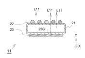
- FIG. 4 and 5 are drawings schematically showing an example of the structure of the excimer lamp 11.
- FIG. 4 is a schematic side view of the excimer lamp 11.
- FIG. 5 is a schematic cross-sectional view of the excimer lamp 11 in FIG. 4 taken along a plane perpendicular to the X1 direction.
- the excimer lamp 11 includes a tube body 21 and a pair of electrodes (22, 23).
- the tube body 21 has a double tube structure. More specifically, as shown in FIG. 5, the tube body 21 includes an outer tube 21a that has a cylindrical shape and is located on the outside, and is arranged coaxially with the outer tube 21a inside the outer tube 21a.
- the inner tube 21b has a cylindrical shape and has an outer diameter smaller than the inner diameter of the inner tube 21a.
- the excimer lamp 11 shown in FIGS. 4 and 5 is arranged such that the tube axis direction of the tube body 21 is along the flow direction (X direction) of the source gas Ga and the non-source gas G3.
- the tube axis direction of the tube body 21 does not necessarily have to be parallel to the X direction, and this drawing is just an example.
- the following explanation will be given assuming that the tube axis direction of the tube body 21 is the X direction, which is the same as the flow direction of the source gas Ga and the non-source gas G3.
- Both the outer tube 21a and the inner tube 21b are sealed at their ends in the X direction (not shown), and there is an annular shape (here, an annular shape) when viewed along the X direction.
- a light-emitting space exhibiting a shape) is formed.
- This light-emitting space is filled with a light-emitting gas 25G that forms excimer molecules by electric discharge.
- first electrode 22 is provided on the outer wall of the outer tube 21a.
- the first electrode 22 has a mesh shape or a linear shape.
- a rod-shaped second electrode 23 extending along the tube axis direction of the tube body 21 is inserted inside the inner tube 21b.
- the outer tube 21a and the inner tube 21b are made of a dielectric material, such as synthetic quartz glass, that is transparent to ultraviolet light L11, for example.
- the electrodes (22, 23) are made of a metal material such as stainless steel, aluminum, copper, tungsten, titanium, or nickel.
- the wavelength of the ultraviolet light L11 emitted from the tube body 21 is determined by the material of the luminescent gas 25G.
- this excimer light emission becomes ultraviolet light L11 having a peak wavelength near 172 nm.
- the ultraviolet rays L11 are extracted to the outside of the outer tube 21a through the gap between the first electrodes 22.
- the light source arrangement space 16 exists outside the excimer lamp 11, through which the non-source gas G3 containing nitrogen as a main component flows. Nitrogen is not absorbed by ultraviolet light L11.
- the tube body 18 is made of a material that is transparent to the ultraviolet light L11. Therefore, the ultraviolet light L11 emitted from the excimer lamp 11 travels within the light source arrangement space 16 and then is irradiated into the ozone generation space 15 located outside the tube body 18 via the tube wall of the tube body 18. . In this way, the high-pressure raw material gas Ga flowing through the ozone generation space 15 is irradiated with the ultraviolet rays L11, and the high-pressure ozone-containing gas Gb is generated.
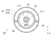
- the second electrode 23 located inside the inner tube 21b may have a membrane shape provided along the wall of the inner tube 21b (see FIG. 6).
- the high-pressure ozone-containing gas Gb generated by the ozone generator 10 is sent to a location depending on the purpose of use.
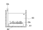
- high-pressure ozone-containing gas Gb may be supplied to the diffuser plate 62.
- a diffuser plate 62 is arranged in a storage tank 61 in which liquid 63 is stored.
- High-pressure ozone-containing gas Gb is bubbled into the liquid 63 via the diffuser plate 62 .
- the liquid 63 include liquids to be cleaned and sterilized, such as water, wastewater, sludge, and liquid foods.
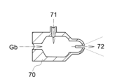
- a liquid 71 and a high-pressure ozone-containing gas Gb may be introduced into the gas-liquid mixing device 70.
- a liquid 72 containing ozone in the form of microbubbles is generated.
- a gas-liquid mixing pump or an ejector can be used as the gas-liquid mixing device 70.
- the first exhaust port 32 through which the ozone-containing gas Gb is exhausted and the devices that utilize the ozone-containing gas Gb are made of highly ozone-resistant materials (PTFE, stainless steel, etc.). ) may be connected by piping.
- the excimer lamp 11 is configured to cause discharge to occur in a luminescent gas 25G sealed in a luminescent space that is independent of the ozone generation space 15 through which the source gas Ga flows. Then, the raw material gas Ga is irradiated with the ultraviolet rays L11 generated along with this discharge, thereby generating the ozone-containing gas Gb. Even if the source gas Ga is made to have a high pressure or the pressure of the source gas Ga is changed, the intensity of the ultraviolet rays L11 is hardly affected. Therefore, by introducing the high-pressure raw material gas Ga, it becomes possible to stably generate the high-pressure ozone-containing gas Gb.
- FIG. 9 is a diagram illustrating the ozone generator 10 of this embodiment, similar to FIG. 2.
- FIG. 10 is a schematic cross-sectional view of the ozone generator 10 of FIG. 9 taken along a plane perpendicular to the X direction.
- the ozone generation space 15 through which the source gas Ga flows is located so as to surround the outside of the light source arrangement space 16 in which the excimer lamp 11 is arranged.
- the ozone generation space 15 does not surround the outer periphery of the light source arrangement space 16, but is adjacent to the light source arrangement space 16 in a predetermined direction (Y direction).
- FIG. 11 is a plan view schematically showing the structure of the excimer lamp 11 included in the ozone generator 10 of this embodiment.
- FIG. 12 is a schematic cross-sectional view of the excimer lamp 11 of FIG. 11 taken along a plane perpendicular to the X direction.
- the excimer lamp 11 of this embodiment includes a single tube body 21 and electrodes (22, 23) provided on the outer wall of the tube body 21.
- a linear or mesh-shaped first electrode 22 is provided on the outer wall of the tube body 21 located on the ozone generation space 15 side, that is, on the +Y side.
- a second membrane-shaped electrode 23 is provided on the outer wall of the tube body 21 on the side opposite to the ozone generation space 15, that is, on the ⁇ Y side.
- the second electrode 23 is made of a material that is reflective to the ultraviolet light L11.
- the second electrode 23 is made of aluminum, stainless steel, or the like.
- the ultraviolet light L11 emitted by the excimer lamp 11 travels to the +Y side of the excimer lamp 11 through the gap between the first electrodes 22, either directly or after being reflected by the second electrode 23.
- the space 15 is irradiated. Therefore, the high-pressure raw material gas Ga flowing through the ozone generation space 15 is irradiated with the ultraviolet rays L11, and the high-pressure ozone-containing gas Gb is generated.
- the ozone generation space 15 through which the source gas Ga flows is located so as to surround the outside of the light source arrangement space 16 in which the excimer lamp 11 is arranged.
- this embodiment differs from the first embodiment in that the light source arrangement space 16 takes in the outside of the ozone generation space 15. More specifically, in this embodiment, the emission space of the excimer lamp 11 has an annular shape, and an ozone generation space 15 through which the source gas Ga flows is formed inside the annular emission space.
- FIG. 13 is a side view schematically showing the structure of the ozone generator 10 of this embodiment, and is illustrated following FIG. 2.
- FIG. 14 is a schematic cross-sectional view of the ozone generator 10 of FIG. 13 taken along a plane perpendicular to the X direction.
- an excimer lamp 11 including a tube body 21 with a double tube structure is arranged inside the casing 19.
- the tube body 21 includes an outer tube 21a and an inner tube 21b.
- the outer tube 21a is sealed at the end in the X direction.
- the inner tube 21b is open at both ends in the X direction, and communicates with a first introduction port 31 through which the raw material gas Ga is introduced and a first exhaust port 32 through which the ozone-containing gas Gb is exhausted. (See Figure 13).
- a pair of electrodes (22, 23) are provided at positions spaced apart from each other on the outside of the tube wall of the outer tube 21a.
- both electrodes (22, 23) have a membrane shape.
- a reflective film 27 is provided inside the tube wall of the outer tube 21a.
- the reflective film 27 is made of a material that is reflective to ultraviolet rays L11, and is made of metal such as aluminum or stainless steel.
- the space sandwiched between the outer tube 21a and the inner tube 21b constitutes a light-emitting space in which the light-emitting gas 25G is sealed.
- the space sandwiched between the housing 19 and the outer tube 21a is connected to a second inlet 35 through which the non-raw material gas G3 for cooling is introduced, and a second exhaust port 36 through which the non-raw material gas G3 is exhausted. (See Figure 13).
- the ozone generation space 15 corresponds to the inside of the excimer lamp 11, more specifically to the space surrounded by the inner tube 21b.
- the light source arrangement space 16 corresponds to the inside of the housing 19.
- the tube body 21 of the excimer lamp 11 separates the ozone generation space 15 from the light source arrangement space 16.
- the high-pressure raw material gas Ga introduced from the first introduction port 31 flows in the ozone generation space 15 inside the inner tube 21b of the excimer lamp 11 in the X direction. While the source gas Ga is flowing in the X direction within the ozone generation space 15, it is irradiated with ultraviolet light L11 generated within the light emitting space of the excimer lamp 11 via the inner tube 21b. Note that among the ultraviolet rays L11 generated within the light emitting space of the excimer lamp 11, the ultraviolet rays L11 traveling outward are reflected by the reflective film 27 and then directed toward the ozone generation space 15 inside the inner tube 21b. proceed.
- the non-raw material gas G3 containing nitrogen as a main component introduced from the second inlet 35 flows in the X direction inside the light source arrangement space 16 which is outside the outer tube 21a of the excimer lamp 11. do.
- This non-raw material gas G3 contacts the tube wall of the excimer lamp 11 arranged in the light source arrangement space 16 and cools the excimer lamp 11.
- FIG. 15 is a cross-sectional view schematically showing another configuration example of the ozone generator 10 of this embodiment.
- the first electrode 22 may be placed so as to surround the outside of the wall of the outer tube 21a, and the second electrode 23 may be placed inside the wall of the inner tube 21b.
- the second electrode 23 has a linear shape or a mesh shape so as not to block the progress of the ultraviolet rays L11.
- the first electrode 22 is made of a material that is reflective to ultraviolet light L11.
- FIG. 16 is a drawing schematically showing the configuration of the ozone-containing gas generation system 1 of this embodiment. As shown in FIG. 16, in the ozone-containing gas generation system 1 of this embodiment, the non-raw material gas G3 is not introduced into the ozone generator 10.
- FIG. 17 is a side view schematically showing the configuration of the ozone generator 10 of this embodiment.
- a cylindrical tube body 18 is disposed within the housing 19.
- the excimer lamp 11 is arranged within this tube body 18.
- the outside of the pipe body 18 constitutes an ozone generation space 15 through which the raw material gas Ga flows.
- the tubular body 18 is not essential. That is, as shown in FIG. 18, the excimer lamp 11 may be placed directly within the housing 19. In this case, high-pressure source gas Ga flows around the outer periphery of the excimer lamp 11 .
- the excimer lamp 11 described in each of the above embodiments is an example of an ultraviolet light source that emits ultraviolet light L11.
- another lamp that emits ultraviolet light L11 may be used, or a solid-state light source such as an LED may be used.
- Ozone-containing gas generation system 10 Ozone generator 11: Excimer lamp 15: Ozone generation space 16: Light source arrangement space 18: Tube 19: Housing 21: Tube 21a: Outer tube 21b: Inner tube 22: First electrode 23 : Second electrode 25G : Luminous gas 27 : Reflective film 31 : First inlet 32 : First exhaust port 35 : Second inlet 36 : Second exhaust port 51 : Compressor 52 : Dehumidifier 53 : Gas Separation device 61: Storage tank 62: Diffusion plate 63: Liquid 70: Gas-liquid mixing device 71: Liquid 72: Liquid G1: High pressure air G2: High pressure air G3: Non-source gas Ga: Source gas Gb: Ozone-containing gas L11: Ultraviolet light W1: Moisture
Landscapes
- Chemical & Material Sciences (AREA)
- Organic Chemistry (AREA)
- Physics & Mathematics (AREA)
- Engineering & Computer Science (AREA)
- Plasma & Fusion (AREA)
- Inorganic Chemistry (AREA)
- Oxygen, Ozone, And Oxides In General (AREA)
Abstract
従来よりも圧力の高いオゾン含有ガスを、簡易な構造で製造することのできる方法及びシステムを提供する。 オゾン含有ガス発生方法は、酸素を含む原料ガスを大気圧よりも高圧にした状態でオゾン生成用空間に導入する工程(a)と、オゾン生成用空間内においてエキシマランプから出射された紫外線を原料ガスに照射する工程(b)と、工程(b)によって生成された、大気圧よりも高圧のオゾン含有ガスをオゾン生成用空間の外側に排気する工程(c)とを有する。
Description
本発明は、オゾン含有ガスを発生する方法に関し、特に大気圧よりも高圧のオゾン含有ガスを発生する方法に関する。また、本発明は、このような方法の実施に適したシステムに関する。
従来、有機物を含む廃水を処理するためにオゾンを供給する技術が知られている(例えば、特許文献1参照)。
しかしながら、本発明者の鋭意研究により、特許文献1で提案されているシステムは利用できる条件に制約があることを突き止めた。この点について、以下で説明する。
処理対象となる廃水は、活性汚泥を初めとする含有有機物の種類及び密度によって、粘性が変化する。液体に対してガスを供給する場合、当該液体の粘度に応じてガスの圧力が変化する。また、ガスを供給する手段として、どのような装置を採用するかによっても、供給されるガスの圧力が影響を受ける。例えば、エゼクターによってガスを供給するのか、散気板によってガスを供給するのかによって、供給されるガスの圧力が変化する。散気板を用いる場合には、ガスを噴射するための孔部の径によっても、供給されるガスの圧力が影響を受ける。
上記特許文献1で提案されているシステムは、無声放電方式のオゾン発生装置を利用したものである。上記特許文献1で提案されているシステムを利用して、粘度が高い廃水に対してオゾン含有ガスを供給しようとすると、オゾン含有ガスを生成するための原料ガスの圧力が上昇する。放電開始電圧と放電空間内のガス圧力との間には、パッシェンの法則が成立する。つまり、原料ガスの圧力が上昇すると、放電開始電圧も上昇する。
よって、上記特許文献1で提案されているシステムを種々の環境下で利用しようとすると、原料ガスの圧力を検知して、検知された圧力に応じてオゾン発生装置に対して印加する電圧を調整する機構が必要となる。無声放電方式のオゾン発生装置においては、kVオーダーの電圧の印加が必要である。つまり、kVオーダーの電圧の範囲で印加電圧を調整する機構が必要となることを意味するが、このような電圧調整は、高電圧回路の構成上、現実的とはいえない。
具体的には、無声放電方式のオゾン発生装置においては、kVオーダーの電圧を生成する必要があるため、電源回路に変圧器を備えるのが通常である。変圧器の変圧比を調整することで、電圧の調整が可能である。しかし、変圧比の調整には変圧器の巻数比の調整が必要となり、巻数比の調整範囲には制限があるため、結果的に、出力電圧の変動幅には制約が生じる。また、高電圧になるほど、絶縁体の厚みや空間距離の確保が必要となるため、高電圧に対応させるために装置規模を大型化する必要がある。
このような事情から、通常の無声放電式のオゾン発生装置は、対応可能なガス圧力に制限が課せられており、制限を超えるガス圧力になった段階で放電が停止される。
また、オゾン含有ガスを捕集した後に加圧するという方法は、オゾンは反応性が高く、捕集中にオゾンが分解される可能性が高いため、採用できない。
以上の事情により、特許文献1で提案されているシステムでは、例えば、粘性の高い液体に対してオゾン含有ガスを吹き込むことが困難となる。具体的には、散気板を用いて液体内にオゾン含有ガスを導入すると、対象となる液体の粘性が高い場合にはガス圧力が高まりやすい。
また、粘性の高い廃水に対する処理の用途に限らず、オゾン含有ガスを高圧で液体に注入することで、オゾン含有ガスがマイクロバブル化された状態の液体を生成する場面でも、上記特許文献1で提案されているシステムでは限界が生じる。なぜなら、上述したように、特許文献1で提案されているシステムでは原料ガスに加えられる圧力に制約が課せられ、マイクロバブル化のために必要な圧力を有するオゾン含有ガスを生成することが困難となるからである。
更に、上述したように、ガスを供給する手段に応じてガスの圧力が変動するため、ガス供給手段によっては、ガス圧力が高圧になる可能性がある。このような事情から、特許文献1で提案されているシステムは、多様なガス供給手段に対応させることが難しい。
本発明は、上記の課題に鑑み、従来よりも圧力の高いオゾン含有ガスを、簡易な構造で製造することのできる方法及びシステムを提供することを目的とする。
本発明に係るオゾン含有ガス発生方法は、酸素を含む原料ガスを大気圧よりも高圧にした状態でオゾン生成用空間に導入する工程(a)と、
前記オゾン生成用空間内において、紫外光源から出射されたピーク波長が200nm未満の紫外線を、前記原料ガスに照射する工程(b)と、
前記工程(b)によって生成された、大気圧よりも高圧のオゾン含有ガスを前記オゾン生成用空間の外側に排気する工程(c)とを有することを特徴とする。
前記オゾン生成用空間内において、紫外光源から出射されたピーク波長が200nm未満の紫外線を、前記原料ガスに照射する工程(b)と、
前記工程(b)によって生成された、大気圧よりも高圧のオゾン含有ガスを前記オゾン生成用空間の外側に排気する工程(c)とを有することを特徴とする。
上記の方法は、原料ガスに対して放電を生じさせてオゾン含有ガスを生成する方法とは異なり、酸素を含む原料ガスに対して紫外線を照射することでオゾン含有ガスを生成する方法である。このため、原料ガスの圧力に対してパッシェンの法則が適用されない。よって、オゾン生成用空間に導入する原料ガスの圧力を高圧にすることが可能となる。また、放電式のオゾン発生装置と異なり、原料ガスの圧力が変動しても、オゾン含有ガスの発生には左右されない。
紫外光源は、酸素分子に対する吸収性が比較的高い波長範囲の紫外線を発する構成であるのが好ましい。典型的には、前記紫外線のピーク波長は200nm未満である。紫外光源としては、エキシマランプに代表される誘電体バリア放電式のランプ、又はLED等の固体光源を利用することができる。
酸素分子は、200nm未満の紫外域にシューマン・ルンゲ帯(Schumann-Runge Bands)と呼ばれる吸収域を有している。このため、オゾン生成用空間内に導入された原料ガスに含まれる酸素分子に対して200nm未満の波長の紫外線が照射されると、下記(1)式に従って原子状酸素に分解される。
O2 + hν(λ) → O + O ‥‥(1)
O2 + hν(λ) → O + O ‥‥(1)
一部の原子状酸素は、原料ガスに含まれる酸素分子と反応してオゾンを生成する。なお、(2)式においてMは第三体を示す(以下同様)。
O + O2 + M → O3 + M ‥‥(2)
O + O2 + M → O3 + M ‥‥(2)
大気圧よりも高圧の状態で導入された原料ガスに対して紫外線が照射されることで、上記(1)式及び(2)式を経て、オゾンを含む高圧のガスが生成される。上記方法によれば、高圧のオゾン含有ガスがオゾン生成用空間内で生成され、オゾン生成用空間の外側に排気される。
つまり、上記の方法によれば、従来よりも高圧のオゾン含有ガスを簡易な構成によって製造できる。また、オゾン含有ガスの吹き込み先の粘度にかかわらず、オゾン含有ガスを安定的に生成することが可能である。更に、オゾン含有ガスを吹き込む際に利用される手段によるガス圧力の変動にも対応可能となるため、オゾン含有ガスの吹き込みに際して多様な手段を採用することができる。
前記工程(a)は、0.2MPaよりも高い圧力で前記原料ガスを前記オゾン生成用空間内に導入する工程であるものとしても構わない。典型的には、前記原料ガスの圧力を0.25MPa~0.95MPaとすることが可能である。
例えば、コンプレッサで大気を加圧した後、加圧空気をそのまま原料ガスとして利用することもできるし、加圧空気から酸素と窒素を分離した後、酸素を主成分とする分離ガスを原料ガスとして利用することもできる。いずれの場合においても、コンプレッサ側で調整された圧力の原料ガスを用いてオゾン含有ガスを生成することが可能となる。
上記オゾン含有ガス発生方法は、前記紫外光源が配置されている光源配置空間内に冷却用ガスを通流させる工程(d)を有し、
前記光源配置空間と前記オゾン生成用空間とが、前記紫外線に対して透過性を示す材料からなる壁部を隔てて隣接した位置に配置されているものとしても構わない。
前記光源配置空間と前記オゾン生成用空間とが、前記紫外線に対して透過性を示す材料からなる壁部を隔てて隣接した位置に配置されているものとしても構わない。
上記方法によれば、紫外光源からの発熱を冷却しつつ、高圧のオゾン含有ガスを発生させることが可能となり、長時間の運転によってもオゾン発生効率の低下が抑制される。
特に、紫外光源をエキシマランプで構成する場合、エキシマランプの構造によっては、エキシマランプの管壁と電極との間にガスが入り込む微小な空間が生まれることがある。
もし、エキシマランプが配置されている空間(光源配置空間)とオゾン生成用空間とが共通である場合、すなわち、原料ガスが導入されるオゾン生成用空間内にエキシマランプが配置されている場合、高圧の原料ガスが前記微小な空間に入り込む可能性がある。このとき、エキシマランプの放電開始電圧が高くなる懸念がある。
もし、エキシマランプが配置されている空間(光源配置空間)とオゾン生成用空間とが共通である場合、すなわち、原料ガスが導入されるオゾン生成用空間内にエキシマランプが配置されている場合、高圧の原料ガスが前記微小な空間に入り込む可能性がある。このとき、エキシマランプの放電開始電圧が高くなる懸念がある。
これに対し、上記の方法のように、紫外光源が配置される空間を高圧の原料ガスが導入されるオゾン生成用空間とは別の空間とすることで、高圧の原料ガスが導入される態様においても、紫外光源が備える電極の構造によらず、放電開始電圧への影響が回避できる。
前記オゾン含有ガス発生方法は、加圧空気から、前記原料ガスと、窒素を含む非原料ガスとに分離する工程(e)を有し、
前記工程(a)は、前記工程(e)で分離された前記原料ガスを前記オゾン生成用空間に導入する工程であり、
前記工程(d)は、前記工程(e)で分離された前記非原料ガスを、前記冷却用ガスとして前記光源配置空間内に通流させる工程であるものとしても構わない。
前記工程(a)は、前記工程(e)で分離された前記原料ガスを前記オゾン生成用空間に導入する工程であり、
前記工程(d)は、前記工程(e)で分離された前記非原料ガスを、前記冷却用ガスとして前記光源配置空間内に通流させる工程であるものとしても構わない。
加圧空気に対して直接紫外線を照射してオゾン含有ガスを生成する場合と比べて、加圧空気から窒素を分離した状態の原料ガスに対して紫外線を照射してオゾン含有ガスを生成する場合の方が、オゾン生成効率が高い。上記の方法によれば、主成分が酸素である加圧後の原料ガスがオゾン生成用空間に導入されるため、高いオゾン生成効率が実現される。
更に、分離後の窒素を含むガス(非原料ガス)をエキシマランプの冷却用ガスとして利用することができる。
更に、分離後の窒素を含むガス(非原料ガス)をエキシマランプの冷却用ガスとして利用することができる。
本発明に係るオゾン含有ガス発生システムは、
ピーク波長が200nm未満の紫外線を出射する紫外光源と、
酸素を含む原料ガスが大気圧よりも高圧の状態で導入される第一導入口と、
前記第一導入口に連絡され、前記紫外光源からの前記紫外線が照射されるオゾン生成用空間と、
前記第一導入口とは別の場所において前記オゾン生成用空間に連絡され、前記紫外線が照射された後の前記原料ガスであるオゾン含有ガスが、大気圧よりも高圧の状態で排出される第一排気口とを備えたことを特徴とする。
ピーク波長が200nm未満の紫外線を出射する紫外光源と、
酸素を含む原料ガスが大気圧よりも高圧の状態で導入される第一導入口と、
前記第一導入口に連絡され、前記紫外光源からの前記紫外線が照射されるオゾン生成用空間と、
前記第一導入口とは別の場所において前記オゾン生成用空間に連絡され、前記紫外線が照射された後の前記原料ガスであるオゾン含有ガスが、大気圧よりも高圧の状態で排出される第一排気口とを備えたことを特徴とする。
上記システムによれば、高圧のオゾン含有ガスを生成し、排気できる。よって、このシステムで得られた高圧のオゾン含有ガスを、例えば廃水、液状の食品(例えば濃縮された果汁)等、殺菌・洗浄が必要な液体に対して吹き込むことで、容易に殺菌・洗浄を行うことができる。
また、一般的な水に吹き込むことで、殺菌・洗浄能力の高い水(オゾンバブルが含有された水)を生成することができる。この水を用いて、殺菌・洗浄対象物(例えば食品等)を洗浄することで、高い殺菌・洗浄効果が期待される。
前記紫外光源は、前記オゾン生成用空間内に配置されているものとしても構わない。この構成の場合、紫外光源が配置されている空間内を原料ガスが通流する。
前記オゾン含有ガス発生システムは、
筐体と、
前記筐体内に配置され、前記紫外線に対して透過性を示す材料からなる管体とを備え、 前記筐体は、前記第一導入口と、前記オゾン生成用空間と、前記第一排気口とを有し、 前記紫外光源は前記管体内に収容され、
前記紫外光源からの前記紫外線は、前記管体の管壁を介して前記オゾン生成用空間内に照射されるものとしても構わない。。
筐体と、
前記筐体内に配置され、前記紫外線に対して透過性を示す材料からなる管体とを備え、 前記筐体は、前記第一導入口と、前記オゾン生成用空間と、前記第一排気口とを有し、 前記紫外光源は前記管体内に収容され、
前記紫外光源からの前記紫外線は、前記管体の管壁を介して前記オゾン生成用空間内に照射されるものとしても構わない。。
上記システムによれば、高圧の原料ガスが紫外光源が配置されている空間内を通流しない。このため、紫外光源が備える電極の形状にかかわらず、高圧の原料ガスが通流することに起因して紫外光源の放電電圧が上昇する事態が回避される。
前記管体は、冷却用ガスが導入される第二導入口と、前記第二導入口に連絡され前記紫外光源が配置されている光源配置空間と、前記光源配置空間を通流後の前記冷却用ガスが排気される第二排気口とを有するものとしても構わない。
上記構成によれば、紫外光源に対して冷却用ガスが接触するため、紫外光源の発光時に生じる熱に起因した、紫外光源の発光効率の低下、又は紫外光源の短寿命化といった現象の発現を抑制できる。
上記構成において、前記オゾン生成用空間は、前記管体の外側に配置されているものとしても構わない。
前記オゾン含有ガス発生システムは、筐体を備え、
前記紫外光源は、前記筐体内に配置され、内側管及び外側管を含む管体を有し、
前記筐体は、前記第一導入口と、前記オゾン生成用空間と、前記第一排気口とを有し、 前記オゾン生成用空間は、前記内側管の内側に位置するものとしても構わない。
前記紫外光源は、前記筐体内に配置され、内側管及び外側管を含む管体を有し、
前記筐体は、前記第一導入口と、前記オゾン生成用空間と、前記第一排気口とを有し、 前記オゾン生成用空間は、前記内側管の内側に位置するものとしても構わない。
前記オゾン含有ガス発生システムは、加圧空気を、主成分が酸素である前記原料ガスと、主成分が窒素である非原料ガスとに分離するガス分離装置を備え、
前記ガス分離装置で分離された前記原料ガスが、前記第一導入口を介して前記第一管体に導入され、
前記ガス分離装置で分離された前記非原料ガスが、前記第二導入口を介して前記第二管体に導入されるものとしても構わない。
前記ガス分離装置で分離された前記原料ガスが、前記第一導入口を介して前記第一管体に導入され、
前記ガス分離装置で分離された前記非原料ガスが、前記第二導入口を介して前記第二管体に導入されるものとしても構わない。
前記オゾン含有ガス発生システムは、空気を0.2MPaよりも高い圧力に加圧するコンプレッサを備え、
前記コンプレッサで得られた加圧空気が、前記原料ガスとして前記第一導入口に導入されるものとしても構わない。
前記コンプレッサで得られた加圧空気が、前記原料ガスとして前記第一導入口に導入されるものとしても構わない。
前記オゾン含有ガス発生システムは、空気を0.2MPaよりも高い圧力に加圧するコンプレッサを備え、
前記コンプレッサで得られた前記加圧空気が、前記ガス分離装置に供給されるものとしても構わない。
前記コンプレッサで得られた前記加圧空気が、前記ガス分離装置に供給されるものとしても構わない。
本発明によれば、従来よりも高圧のオゾン含有ガスを、簡易な構造の下で生成することが可能となる。
本発明に係るオゾン含有ガスの発生方法、及びオゾン含有ガスの発生システムの実施形態につき、適宜図面を参照しながら以下において説明する。なお、以下の各図面は、模式的に図示されたものであり、図面上の寸法比と実際の寸法比は必ずしも一致していない。
また、各図面間においても、寸法比は必ずしも一致していない。
また、各図面間においても、寸法比は必ずしも一致していない。
[第一実施形態]
図1は、オゾン含有ガスの発生システムの第一実施形態の構成を模式的に示すブロック図である。図1に示すシステム1は、コンプレッサ51、除湿装置52、ガス分離装置53、及びオゾン発生装置10を備える。
図1は、オゾン含有ガスの発生システムの第一実施形態の構成を模式的に示すブロック図である。図1に示すシステム1は、コンプレッサ51、除湿装置52、ガス分離装置53、及びオゾン発生装置10を備える。
コンプレッサ51は、供給される気体に対して圧力を加えて高圧の気体を生成する装置である。ここでは、コンプレッサ51が高圧空気G1を生成するものとして説明する。コンプレッサ51としては、公知の装置が利用可能である。
本実施形態において、コンプレッサ51は、0.2MPaよりも高い圧力の高圧空気G1を生成する。典型的には、高圧空気G1は、0.25MPa~0.95MPaの圧力を示す。
除湿装置52は、コンプレッサ51から送出された高圧空気G1に含まれる水分W1を除去する装置である。ただし、本発明において、システム1が除湿装置52を備えるか否かは任意である。図1に示すシステム1では、除湿後の高圧空気G2がガス分離装置53に送出される。
ガス分離装置53は、高圧空気G2に含まれる窒素を分離する。ガス分離装置53としては、膜分離方式、深冷分離方式、又は吸着分離方式を利用した装置が利用できる。ただし、装置規模を縮小化する観点から、最も簡便に分離できる膜分離方式が好適に採用できる。膜分離方式を利用したガス分離装置53は、「N2セパレータ」と称されることがある。
特許文献1で記載されているように、無声放電方式のオゾン発生装置を用いて空気からオゾン含有ガスを発生する場合、空気中の窒素ガスを厳密に除去することが要求される。
この理由としては、仮に窒素が含まれていると、N2分子が放電によって分離する結果、酸素原子と結合して窒素酸化物(NOx)が生成されてしまうためである。NOxは人体に対して悪影響を及ぼすことが知られている。また、NOxを含むガスを水に吹き込むと硝酸が発生し、生物毒性を示すことも知られている。
この理由としては、仮に窒素が含まれていると、N2分子が放電によって分離する結果、酸素原子と結合して窒素酸化物(NOx)が生成されてしまうためである。NOxは人体に対して悪影響を及ぼすことが知られている。また、NOxを含むガスを水に吹き込むと硝酸が発生し、生物毒性を示すことも知られている。
膜分離方式は、深冷分離方式や吸着分離方式と比べて、装置構造は簡素である反面、窒素の分離精度が低い。このため、無声放電方式のオゾン発生装置を用いて空気からオゾン含有ガスを発生する場合、膜分離方式のガス分離装置53を利用することは現実的ではない。
しかし、後述するように、本システム1は、紫外光源(エキシマランプ11)からの紫外線L11を酸素含有ガスに照射することによって、オゾン含有ガスを生成する。窒素分子は、極めて短い波長(100nm未満)の光に対してのみ吸収性を示す。このため、エキシマランプ11からの紫外線L11のピーク波長を140nm~200nmとすることにより、仮に原料ガスに窒素が含まれていた場合であっても、エキシマランプ11からの紫外線L11によって窒素分子が窒素原子に分離することがない。
したがって、本システム1では、オゾン含有ガスにNOxを含有されないようにするという観点からは、ガス分離装置53において窒素ガスを高精度に分離させる必要がない。
よって、膜分離方式のガス分離装置53を利用することが可能である。
よって、膜分離方式のガス分離装置53を利用することが可能である。
上記の観点からは、本システム1においてガス分離装置53を必ずしも備えなくても構わない。しかし、オゾン発生装置10に供給される原料ガスに窒素が多く含まれていると、窒素はオゾンの生成に関与しないため、生成されるオゾン含有ガスのオゾン濃度が低下する。オゾン含有ガスのオゾン濃度を高める観点からは、ガス分離装置53を用いて高圧空気G2から窒素ガスを分離するのが好適である。
以下では、高圧空気G2から分離された、酸素を主成分とするガスを「原料ガスGa」と称し、窒素を主成分とするガスを「非原料ガスG3」と称する。ここで「主成分」とは、ガス中に含まれる分子の割合が最も高い物質を指す。原料ガスGa及び非原料ガスG3は、高圧空気G2と同様に圧力が高い状態である。ただし、非原料ガスG3については、必ずしも高圧である必要はない。
ガス分離装置53によって、高圧空気G2を、原料ガスGaと非原料ガスG3とに分離する工程が、工程(e)に対応する。
図1に示すシステム1では、原料ガスGa及び非原料ガスG3のいずれもが、オゾン発生装置10に送出される。ただし後述するように、オゾン発生装置10内において、原料ガスGaが通流する配管系統と、非原料ガスG3が通流する配管系統とは異なっている。
オゾン発生装置10は、エキシマランプ11を有している。図1に示すシステム1が備えるオゾン発生装置10には、原料ガスGaを処理する空間(オゾン生成用空間15)と、エキシマランプ11が配置されている空間(光源配置空間16)とが設けられている。
オゾン生成用空間15と光源配置空間16とは、エキシマランプ11からの紫外線L11に対して透過性を示す材料からなる壁によって隔てられている。本実施形態において、エキシマランプ11は、紫外光源の一例である。
オゾン生成用空間15と光源配置空間16とは、エキシマランプ11からの紫外線L11に対して透過性を示す材料からなる壁によって隔てられている。本実施形態において、エキシマランプ11は、紫外光源の一例である。
図2は、図1内のオゾン発生装置10を拡大した図面である。本実施形態において、オゾン発生装置10が有するオゾン生成用空間15内には、高圧の原料ガスGaが導入される。この工程が、工程(a)に対応する。
また、オゾン発生装置10が有する光源配置空間16内には、非原料ガスG3が導入される。
オゾン生成用空間15内に導入された高圧の原料ガスGaは、オゾン生成用空間15内をX方向に通流中に、エキシマランプ11からの紫外線L11が照射される。この工程が、工程(b)に対応する。
エキシマランプ11は、ピーク波長が200nm未満の紫外線L11を発する構成である。例えば、エキシマランプ11に封入される発光ガスがXeを含む場合、エキシマランプ11のピーク波長は172nm近傍を示す。発光ガスの材料を替えることで、紫外線L11の波長を異ならせることができる。例えば、以下の通りである。
発光ガスがKrを含む場合には、紫外線L11のピーク波長が146nm近傍となる。
発光ガスがArBrを含む場合には、紫外線L11のピーク波長が165nm近傍となる。
発光ガスがArFを含む場合には、紫外線L11のピーク波長が193nm近傍となる。
発光ガスがArBrを含む場合には、紫外線L11のピーク波長が165nm近傍となる。
発光ガスがArFを含む場合には、紫外線L11のピーク波長が193nm近傍となる。
なお、上記において、「近傍」と表記したのは、ランプに封入されるガスの分圧や、利用に伴う経時的な変化によって、ピーク波長に±2nm程度の個体差が生じる可能性を許容する意図である。
オゾン発生装置10は、筐体19を有する。筐体19の材料は任意であるが、例えばステンレス等の金属製である。筐体19には、高圧の原料ガスGaを導入するための第一導入口31と、生成されたオゾン含有ガスGbを排気するための第一排気口32が設けられている。更に、筐体19には、非原料ガスG3を導入するための第二導入口35と、筐体19内を通流した非原料ガスG3を排気するための第二排気口36とが設けられている。
図3は、図2に示すオゾン発生装置10を、X方向に直交する平面で切断したときの模式的な断面図である。
図3に示すように、筐体19内には筒状の管体18が配置される。そして、この管体18内に、エキシマランプ11が配置される。
管体18は、エキシマランプ11から出射された紫外線L11に対して透過性を示す材料で構成される。典型的には、管体18は合成石英ガラス製である。
筐体19内の空間のうち、オゾン生成用空間15は、筐体19の内壁と管体18の外壁とに囲まれた空間に対応し、光源配置空間16は、管体18の内壁とエキシマランプ11の管壁とに囲まれた空間に対応する。
つまり、本実施形態において、第一導入口31から導入された高圧の原料ガスGaは、管体18の外側であるオゾン生成用空間15内をX方向に通流する。原料ガスGaは、オゾン生成用空間15内をX方向に通流中に、エキシマランプ11からの紫外線L11が、管体18を介して照射される。
上述したように、原料ガスGaに含まれる酸素分子に対して、200nm未満の波長の紫外線L11が照射されると、下記(1)式に従って原子状酸素に分解される。
O2 + hν(λ) → O + O ‥‥(1)
O2 + hν(λ) → O + O ‥‥(1)
そして、一部の原子状酸素は、原料ガスGaに含まれる酸素分子と反応し、(2)式に従ってオゾンを生成する。(2)式においてMは第三体を示す。
O + O2 + M → O3 + M ‥‥(2)
O + O2 + M → O3 + M ‥‥(2)
つまり、酸素を主成分とする高圧の原料ガスGaは、オゾン生成用空間15内をX方向に通流中に、高圧のオゾン含有ガスGbに変化する。この高圧のオゾン含有ガスGbは、第一排気口32を介して、オゾン発生装置10の外側に排気される。この工程が、工程(c)に対応する。
本実施形態において、第二導入口35から導入された窒素を主成分とする非原料ガスG3は、管体18の内側である光源配置空間16内をX方向に通流する。この非原料ガスG3は、光源配置空間16内に配置されたエキシマランプ11の管壁に接触し、エキシマランプ11を冷却する。つまり、非原料ガスG3は、エキシマランプ11の冷却用ガスとして機能する。非原料ガスG3を冷却用ガスとして光源配置空間16内に導入する工程が、工程(d)に対応する。
図4及び図5は、エキシマランプ11の構造の一例を模式的に示す図面である。図4は、エキシマランプ11の模式的な側面図である。図5は、図4内のエキシマランプ11を、X1方向に直交する平面で切断したときの模式的な断面図である。
エキシマランプ11は、管体21と、一対の電極(22,23)とを備える。本実施形態では、管体21は二重管構造を呈している。より詳細には、図5に示すように、管体21は、円筒形状を呈し外側に位置する外側管21aと、外側管21aの内側において外側管21aと同軸上に配置されており、外側管21aの内径よりも外径が小さい円筒形状を呈した内側管21bとを有する。
なお、図4及び図5に示すエキシマランプ11は、管体21の管軸方向が、原料ガスGa及び非原料ガスG3の通流方向(X方向)に沿うように配置されている。しかし、管体21の管軸方向は、必ずしもX方向と平行にする必要はなく、あくまでこの図面は一例である。例えば、X方向に直交する方向を管軸方向とするエキシマランプ11を、X方向に沿って複数個並べる構成の採用も可能である。以下では、管体21の管軸方向が、原料ガスGa及び非原料ガスG3の通流方向と同じX方向であるものとして説明を行う。
外側管21aと内側管21bとは、共にX方向に係る端部において封止されており(不図示)、両者の間には、X方向に沿って見たときに環形状(ここでは円環形状)を呈する発光空間が形成される。この発光空間内には、放電によってエキシマ分子を形成する発光ガス25Gが封入されている。
外側管21aの外壁には、一方の電極(第一電極22)が配設されている。本実施形態では、この第一電極22はメッシュ形状又は線形状を呈している。また、図5の例では、内側管21bの内側には、管体21の管軸方向に沿って延在する棒状の第二電極23が挿通されている。
外側管21a及び内側管21bは、例えば紫外線L11に対する透過性を示す、合成石英ガラス等の誘電体材料で構成される。電極(22,23)は、例えばステンレス、アルミニウム、銅、タングステン、チタン、ニッケル等の金属材料で構成される。
不図示の点灯電源から、給電線を介して電極(22,23)の間に、例えば1kHz~5MHz程度の高周波の交流電圧が印加されると、発光ガス25Gに対して、管体21を介して前記電圧が印加される。このとき、発光ガス25Gが封入されている発光空間内で放電プラズマが生じ、発光ガス25Gの原子が励起されてエキシマ状態となり、この原子が基底状態に移行する際にエキシマ発光を生じる。
上述したように、発光ガス25Gの材料によって、管体21から発せられる紫外線L11の波長が決定される。発光ガス25GとしてXeを含むガスを用いた場合には、このエキシマ発光は、172nm近傍にピーク波長を有する紫外線L11となる。
上述したように、外側管21aの管壁に設けられた第一電極22が線形状又はメッシュ形状を呈するため、この第一電極22の隙間を通じて紫外線L11が外側管21aの外側に取り出される。図3を参照して上述したように、このエキシマランプ11の外側には、窒素を主成分とする非原料ガスG3が通流する光源配置空間16が存在する。窒素は、紫外線L11に吸収されない。また、上述したように、管体18は紫外線L11に対する透過性を示す材料で構成されている。よって、エキシマランプ11から出射した紫外線L11は、光源配置空間16内を進行した後、管体18の管壁を介して、管体18の外側に位置するオゾン生成用空間15内に照射される。このように、オゾン生成用空間15内を通流する高圧の原料ガスGaに対して紫外線L11が照射され、高圧のオゾン含有ガスGbが生成される。
内側管21bの内側に位置する第二電極23は、内側管21bの管壁に沿って設けられた膜形状であっても構わない(図6参照)。
オゾン発生装置10で生成された高圧のオゾン含有ガスGbは、利用目的に応じた箇所に送出される。例えば、図7に示すように、高圧のオゾン含有ガスGbを散気板62に供給するものとしてもよい。図7に示す例では、液体63が貯留された貯槽61内に散気板62が配置されている。散気板62を介して高圧のオゾン含有ガスGbが、液体63内にバブリングされる。液体63としては、水、廃水、汚泥、液体の食品等、洗浄・殺菌処理の対象となる液体が挙げられる。
別の例として、図8に示すように、気液混合装置70に対して、液体71と高圧のオゾン含有ガスGbが導入されるものとしてもよい。これにより、マイクロバブル化したオゾンを含む液体72が生成される。気液混合装置70としては、気液混合ポンプ、エゼクターを用いることができる。
オゾン含有ガスGbが排気される第一排気口32と、オゾン含有ガスGbを利用する装置(上記の散気板62、気液混合装置等)とは、オゾン耐性の高い材料(PTFE、ステンレス等)からなる配管で連絡されるものとして構わない。
本実施形態のシステム1によれば、原料ガスGaに対して放電を生じさせる必要がない。エキシマランプ11は、原料ガスGaが通流するオゾン生成用空間15とは独立した、発光空間内に封入された発光ガス25Gに対して放電を生じさせる構成である。そして、この放電に伴って生じる紫外線L11が、原料ガスGaに対して照射されることで、オゾン含有ガスGbが生成される。原料ガスGaを高圧にしたり、原料ガスGaの圧力が変動しても、紫外線L11の強度にはほとんど影響が生じない。よって、高圧の原料ガスGaを導入することで、高圧のオゾン含有ガスGbを安定的に生成することが可能となる。
[第二実施形態]
オゾン含有ガスの発生システムの第二実施形態について、第一実施形態と異なる箇所のみを説明する。本実施形態は、第一実施形態と比較して、オゾン発生装置10の構造のみが異なる。
オゾン含有ガスの発生システムの第二実施形態について、第一実施形態と異なる箇所のみを説明する。本実施形態は、第一実施形態と比較して、オゾン発生装置10の構造のみが異なる。
図9は、本実施形態のオゾン発生装置10を、図2にならって図示した図面である。図10は、図9のオゾン発生装置10を、X方向に直交する平面で切断したときの模式的な断面図である。
第一実施形態では、原料ガスGaが通流するオゾン生成用空間15は、エキシマランプ11が配置されている光源配置空間16の外側を取り囲むように位置していた。これに対し、本実施形態では、オゾン生成用空間15は、光源配置空間16の外周を取り囲むのではなく、光源配置空間16に対して所定の方向(Y方向)に隣接している。
図11は、本実施形態のオゾン発生装置10が備えるエキシマランプ11の構造を模式的に示す平面図である。図12は、図11のエキシマランプ11を、X方向に直交する平面で切断したときの模式的な断面図である。
図11~図12に示すように、本実施形態のエキシマランプ11は、単一の管体21と、管体21の外壁に設けられた電極(22,23)を備える。ここで、管体21の外壁のうち、オゾン生成用空間15側、すなわち+Y側に位置する外壁には、線形状又はメッシュ形状の第一電極22が設けられている。また、管体21の外壁のうち、オゾン生成用空間15とは反対側、すなわち-Y側に位置する外壁には、膜形状の第二電極23が設けられている。第二電極23は、紫外線L11に対して反射性を示す材料からなる。例えば、第二電極23は、アルミニウム、ステンレス等で構成される。
かかる構成の場合、エキシマランプ11で発光した紫外線L11は、直接又は第二電極23で反射した後、第一電極22の隙間を通じてエキシマランプ11の+Y側に進行する。第一実施形態と同様、この紫外線L11は、図10に示すように、光源配置空間16内を進行した後、管体18の管壁を介して、管体18の外側に位置するオゾン生成用空間15内に照射される。よって、オゾン生成用空間15内を通流する高圧の原料ガスGaに対して紫外線L11が照射され、高圧のオゾン含有ガスGbが生成される。
[第三実施形態]
オゾン含有ガスの発生システムの第三実施形態について、第一実施形態と異なる箇所のみを説明する。本実施形態は、第一実施形態と比較して、オゾン発生装置10の構造のみが異なる。
オゾン含有ガスの発生システムの第三実施形態について、第一実施形態と異なる箇所のみを説明する。本実施形態は、第一実施形態と比較して、オゾン発生装置10の構造のみが異なる。
第一実施形態では、原料ガスGaが通流するオゾン生成用空間15は、エキシマランプ11が配置されている光源配置空間16の外側を取り囲むように位置していた。これに対し、本実施形態では、光源配置空間16がオゾン生成用空間15の外側を取り込む点が、第一実施形態と異なる。より詳細には、本実施形態においては、エキシマランプ11の発光空間が環状を呈しており、その内側に、原料ガスGaが通流するオゾン生成用空間15が形成される。
図13は、本実施形態のオゾン発生装置10の構造を模式的に示す側面図であり、図2にならって図示されている。図14は、図13のオゾン発生装置10を、X方向に直交する平面で切断したときの模式的な断面図である。
図14に示すように、筐体19内には、二重管構造の管体21を含むエキシマランプ11が配置されている。管体21は、外側管21aと内側管21bとを含む。外側管21aは、X方向に係る端部において封止されている。一方、内側管21bは、X方向に係る両端が開放されており、原料ガスGaが導入される第一導入口31、及びオゾン含有ガスGbが排気される第一排気口32と連絡されている(図13参照)。
外側管21aの管壁の外側には、相互に離間した位置に一対の電極(22,23)が設けられている。図14に示す構造例では、いずれの電極(22,23)も膜形状を呈している。また、外側管21aの管壁の内側には、反射膜27が設けられている。反射膜27は、紫外線L11に対して反射性を示す材料からなり、例えばアルミニウムやステンレス等の金属製である。
外側管21aと内側管21bとに挟まれた空間が、発光ガス25Gが封入された発光空間を構成する点は、第一実施形態と同様である。
筐体19と外側管21aとに挟まれた空間は、冷却用の非原料ガスG3が導入される第二導入口35、及び非原料ガスG3が排気される第二排気口36と連絡されている(図13参照)。
本実施形態において、オゾン生成用空間15は、エキシマランプ11の内側、より詳細には内側管21bに囲まれた空間に対応する。一方、光源配置空間16は筐体19の内側に対応する。本実施形態においては、エキシマランプ11の管体21が、オゾン生成用空間15と光源配置空間16とを隔てている。
本実施形態において、第一導入口31から導入された高圧の原料ガスGaは、エキシマランプ11の内側管21bの内側であるオゾン生成用空間15内をX方向に通流する。原料ガスGaは、オゾン生成用空間15内をX方向に通流中に、エキシマランプ11の発光空間内で発生した紫外線L11が、内側管21bを介して照射される。なお、エキシマランプ11の発光空間内で発生した紫外線L11のうち、外側に進行する紫外線L11については、反射膜27で反射された後、内側管21bの内側であるオゾン生成用空間15に向かって進行する。
また、本実施形態において、第二導入口35から導入された窒素を主成分とする非原料ガスG3は、エキシマランプ11の外側管21aの外側である光源配置空間16内をX方向に通流する。この非原料ガスG3は、光源配置空間16内に配置されたエキシマランプ11の管壁に接触し、エキシマランプ11を冷却する。
図15は、本実施形態のオゾン発生装置10の別の構成例を模式的に示す断面図である。図15に示すように、第一電極22が、外側管21aの管壁の外側を取り囲むように配置され、第二電極23が、内側管21bの管壁の内側に配置されても構わない。第二電極23は、紫外線L11の進行を遮らないよう、線形状又はメッシュ形状を呈する。第一電極22は、紫外線L11に対して反射性を示す材料で構成される。
[第四実施形態]
オゾン含有ガスの発生システムの第四実施形態について、第一実施形態と異なる箇所のみを説明する。
オゾン含有ガスの発生システムの第四実施形態について、第一実施形態と異なる箇所のみを説明する。
図16は、本実施形態のオゾン含有ガスの発生システム1の構成を模式的に示す図面である。図16に示すように、本実施形態のオゾン含有ガスの発生システム1では、非原料ガスG3が、オゾン発生装置10に導入されない。
図17は、本実施形態のオゾン発生装置10の構成を模式的に示す側面図である。図17に示すように、筐体19内には筒状の管体18が配置される。そして、この管体18内に、エキシマランプ11が配置される。筐体19内において、管体18の外側が原料ガスGaが通流するオゾン生成用空間15を構成する。
本実施形態において、管体18は必須ではない。すなわち、図18に示すように、筐体19内に直接エキシマランプ11が配置されても構わない。この場合、エキシマランプ11の外周を高圧の原料ガスGaが通流する。
[別実施形態]
上述した各実施形態は、適宜組み合わせることが可能である。なお、上記各実施形態で説明したエキシマランプ11は、紫外線L11を発する紫外光源の一例である。上記各実施形態において、エキシマランプ11に替えて、紫外線L11を発する他のランプを採用しても構わないし、LED等の固体光源を採用しても構わない。
上述した各実施形態は、適宜組み合わせることが可能である。なお、上記各実施形態で説明したエキシマランプ11は、紫外線L11を発する紫外光源の一例である。上記各実施形態において、エキシマランプ11に替えて、紫外線L11を発する他のランプを採用しても構わないし、LED等の固体光源を採用しても構わない。
1 :オゾン含有ガスの発生システム
10 :オゾン発生装置
11 :エキシマランプ
15 :オゾン生成用空間
16 :光源配置空間
18 :管体
19 :筐体
21 :管体
21a :外側管
21b :内側管
22 :第一電極
23 :第二電極
25G :発光ガス
27 :反射膜
31 :第一導入口
32 :第一排気口
35 :第二導入口
36 :第二排気口
51 :コンプレッサ
52 :除湿装置
53 :ガス分離装置
61 :貯槽
62 :散気板
63 :液体
70 :気液混合装置
71 :液体
72 :液体
G1 :高圧空気
G2 :高圧空気
G3 :非原料ガス
Ga :原料ガス
Gb :オゾン含有ガス
L11 :紫外線
W1 :水分
10 :オゾン発生装置
11 :エキシマランプ
15 :オゾン生成用空間
16 :光源配置空間
18 :管体
19 :筐体
21 :管体
21a :外側管
21b :内側管
22 :第一電極
23 :第二電極
25G :発光ガス
27 :反射膜
31 :第一導入口
32 :第一排気口
35 :第二導入口
36 :第二排気口
51 :コンプレッサ
52 :除湿装置
53 :ガス分離装置
61 :貯槽
62 :散気板
63 :液体
70 :気液混合装置
71 :液体
72 :液体
G1 :高圧空気
G2 :高圧空気
G3 :非原料ガス
Ga :原料ガス
Gb :オゾン含有ガス
L11 :紫外線
W1 :水分
Claims (15)
- 酸素を含む原料ガスを大気圧よりも高圧にした状態でオゾン生成用空間に導入する工程(a)と、
前記オゾン生成用空間内において、紫外光源から出射されたピーク波長が200nm未満の紫外線を、前記原料ガスに照射する工程(b)と、
前記工程(b)によって生成された、大気圧よりも高圧のオゾン含有ガスを前記オゾン生成用空間の外側に排気する工程(c)とを有することを特徴とする、オゾン含有ガス発生方法。 - 前記工程(a)は、0.2MPaよりも高い圧力で前記原料ガスを前記オゾン生成用空間内に導入する工程であることを特徴とする、請求項1に記載のオゾン含有ガス発生方法。
- 前記紫外光源が配置されている光源配置空間内に、冷却用ガスを通流させる工程(d)を有し、
前記光源配置空間と前記オゾン生成用空間とが、前記紫外線に対して透過性を示す材料からなる壁部を隔てて隣接した位置に配置されていることを特徴とする、請求項1に記載のオゾン含有ガス発生方法。 - 加圧空気から、前記原料ガスと、窒素を含む非原料ガスとに分離する工程(e)を有し、
前記工程(a)は、前記工程(e)で分離された前記原料ガスを前記オゾン生成用空間に導入する工程であり、
前記工程(d)は、前記工程(e)で分離された前記非原料ガスを、前記冷却用ガスとして前記光源配置空間内に通流させる工程であることを特徴とする、請求項3に記載のオゾン含有ガス発生方法。 - 前記紫外光源はエキシマランプであることを特徴とする、請求項1~4のいずれか1項に記載のオゾン含有ガス発生方法。
- ピーク波長が200nm未満の紫外線を出射する紫外光源と、
酸素を含む原料ガスが大気圧よりも高圧の状態で導入される第一導入口と、
前記第一導入口に連絡され、前記紫外光源からの前記紫外線が照射されるオゾン生成用空間と、
前記第一導入口とは別の場所において前記オゾン生成用空間に連絡され、前記紫外線が照射された後の前記原料ガスであるオゾン含有ガスが、大気圧よりも高圧の状態で排出される第一排気口とを備えたことを特徴とする、オゾン含有ガス発生システム。 - 前記紫外光源は、前記オゾン生成用空間内に配置されていることを特徴とする、請求項6に記載のオゾン含有ガス発生システム。
- 筐体と、
前記筐体内に配置され、前記紫外線に対して透過性を示す材料からなる管体とを備え、 前記筐体は、前記第一導入口と、前記オゾン生成用空間と、前記第一排気口とを有し、 前記紫外光源は前記管体内に収容され、
前記紫外光源からの前記紫外線は、前記管体の管壁を介して前記オゾン生成用空間内に照射されることを特徴とする、請求項6に記載のオゾン含有ガス発生システム。 - 前記管体は、冷却用ガスが導入される第二導入口と、前記第二導入口に連絡され前記紫外光源が配置されている光源配置空間と、前記光源配置空間を通流後の前記冷却用ガスが排気される第二排気口とを有することを特徴とする、請求項8に記載のオゾン含有ガス発生システム。
- 前記オゾン生成用空間は、前記管体の外側に配置されていることを特徴とする、請求項8に記載のオゾン含有ガス発生システム。
- 筐体を備え、
前記紫外光源は、前記筐体内に配置され、内側管及び外側管を含む管体を有し、
前記筐体は、前記第一導入口と、前記オゾン生成用空間と、前記第一排気口とを有し、 前記オゾン生成用空間は、前記内側管の内側に位置することを特徴とする、請求項6に記載のオゾン含有ガス発生システム。 - 加圧空気を、主成分が酸素である前記原料ガスと、主成分が窒素である非原料ガスとに分離するガス分離装置を備え、
前記ガス分離装置で分離された前記原料ガスが、前記第一導入口を介して前記第一管体に導入され、
前記ガス分離装置で分離された前記非原料ガスが、前記第二導入口を介して前記第二管体に導入されることを特徴とする、請求項7~11のいずれか1項に記載のオゾン含有ガス発生システム。 - 空気を0.2MPaよりも高い圧力に加圧するコンプレッサを備え、
前記コンプレッサで得られた加圧空気が、前記原料ガスとして前記第一導入口に導入されることを特徴とする、請求項6~11のいずれか1項に記載のオゾン含有ガス発生システム。 - 空気を0.2MPaよりも高い圧力に加圧するコンプレッサを備え、
前記コンプレッサで得られた前記加圧空気が、前記ガス分離装置に供給されることを特徴とする、請求項12に記載のオゾン含有ガス発生システム。 - 前記紫外光源はエキシマランプであることを特徴とする、請求項6~11のいずれか1項に記載のオゾン含有ガス発生方法。
Applications Claiming Priority (2)
| Application Number | Priority Date | Filing Date | Title |
|---|---|---|---|
| JP2022-097790 | 2022-06-17 | ||
| JP2022097790A JP2023183958A (ja) | 2022-06-17 | 2022-06-17 | オゾン含有ガス発生方法、オゾン含有ガス発生システム |
Publications (1)
| Publication Number | Publication Date |
|---|---|
| WO2023243288A1 true WO2023243288A1 (ja) | 2023-12-21 |
Family
ID=89191069
Family Applications (1)
| Application Number | Title | Priority Date | Filing Date |
|---|---|---|---|
| PCT/JP2023/018242 Ceased WO2023243288A1 (ja) | 2022-06-17 | 2023-05-16 | オゾン含有ガス発生方法、オゾン含有ガス発生システム |
Country Status (2)
| Country | Link |
|---|---|
| JP (1) | JP2023183958A (ja) |
| WO (1) | WO2023243288A1 (ja) |
Citations (5)
| Publication number | Priority date | Publication date | Assignee | Title |
|---|---|---|---|---|
| JP2014148937A (ja) * | 2013-02-01 | 2014-08-21 | Hino Motors Ltd | 排気浄化システム及びオゾン生成装置 |
| JP2016037416A (ja) * | 2014-08-07 | 2016-03-22 | ウシオ電機株式会社 | 紫外線照射式オゾン生成装置 |
| JP2019206463A (ja) * | 2018-05-30 | 2019-12-05 | 東洋紡エンジニアリング株式会社 | オゾンガスの製造方法及びオゾン溶解水の製造方法 |
| JP2020011856A (ja) * | 2018-07-17 | 2020-01-23 | ウシオ電機株式会社 | オゾン発生装置およびオゾン発生装置を備える処理システム |
| CN112441563A (zh) * | 2020-08-21 | 2021-03-05 | 郑州圣华药物食品技术开发有限公司 | 集中传输式氙准分子光源臭氧发生器 |
-
2022
- 2022-06-17 JP JP2022097790A patent/JP2023183958A/ja active Pending
-
2023
- 2023-05-16 WO PCT/JP2023/018242 patent/WO2023243288A1/ja not_active Ceased
Patent Citations (5)
| Publication number | Priority date | Publication date | Assignee | Title |
|---|---|---|---|---|
| JP2014148937A (ja) * | 2013-02-01 | 2014-08-21 | Hino Motors Ltd | 排気浄化システム及びオゾン生成装置 |
| JP2016037416A (ja) * | 2014-08-07 | 2016-03-22 | ウシオ電機株式会社 | 紫外線照射式オゾン生成装置 |
| JP2019206463A (ja) * | 2018-05-30 | 2019-12-05 | 東洋紡エンジニアリング株式会社 | オゾンガスの製造方法及びオゾン溶解水の製造方法 |
| JP2020011856A (ja) * | 2018-07-17 | 2020-01-23 | ウシオ電機株式会社 | オゾン発生装置およびオゾン発生装置を備える処理システム |
| CN112441563A (zh) * | 2020-08-21 | 2021-03-05 | 郑州圣华药物食品技术开发有限公司 | 集中传输式氙准分子光源臭氧发生器 |
Also Published As
| Publication number | Publication date |
|---|---|
| JP2023183958A (ja) | 2023-12-28 |
Similar Documents
| Publication | Publication Date | Title |
|---|---|---|
| JPH0899082A (ja) | 紫外線による流動体の処理装置 | |
| JP2009542437A (ja) | 放射線源及び冷却手段を含む流体処理システム | |
| JP7145597B2 (ja) | オゾン生成装置およびエキシマランプ点灯方法 | |
| JP2023183958A (ja) | オゾン含有ガス発生方法、オゾン含有ガス発生システム | |
| JP7539273B2 (ja) | オゾン発生装置およびオゾン発生方法 | |
| Horikoshi et al. | Development of a Hg-free UV light source and its performance in photolytic and photocatalytic applications | |
| JP6871038B2 (ja) | 放電ランプ、オゾン生成装置およびオゾン生成方法 | |
| JP2013154145A (ja) | 空気浄化装置 | |
| RU2142915C1 (ru) | Способ обработки водных сред, содержащих органические примеси | |
| US20170144898A1 (en) | Device for the Photochemical Treatment of Polluted Water | |
| JP4516251B2 (ja) | 紫外線照射装置及びその運用方法 | |
| JP7158896B2 (ja) | オゾンガスの製造方法及びオゾン溶解水の製造方法 | |
| JP2020185532A (ja) | 紫外線照射装置、及びこれを備えた気体処理装置 | |
| CN105810552A (zh) | 一种短波紫外光产生方法及其装置 | |
| CN203474455U (zh) | 臭氧发生器 | |
| CN103407968A (zh) | 臭氧发生器 | |
| JP2623497B2 (ja) | オゾン水活性化装置 | |
| JPH06100301A (ja) | オゾン発生装置 | |
| WO2002024587A1 (fr) | Verre de silice pour rayons ultraviolets a courte longueur d'ondes, lampe a decharge comprenant ce verre, receptacle pour cette lampe et dispositif a rayonnement ultraviolet | |
| JP2005235607A (ja) | 光処理装置 | |
| RU63224U1 (ru) | Устройство для обеззараживания воздуха и жидких сред | |
| JP7307895B2 (ja) | ガス供給装置 | |
| JP6728962B2 (ja) | 水処理装置 | |
| JP2021106240A (ja) | ガス供給装置、表面処理方法 | |
| JP7687665B2 (ja) | 水処理装置および水処理方法 |
Legal Events
| Date | Code | Title | Description |
|---|---|---|---|
| 121 | Ep: the epo has been informed by wipo that ep was designated in this application |
Ref document number: 23823589 Country of ref document: EP Kind code of ref document: A1 |
|
| NENP | Non-entry into the national phase |
Ref country code: DE |
|
| 122 | Ep: pct application non-entry in european phase |
Ref document number: 23823589 Country of ref document: EP Kind code of ref document: A1 |